1
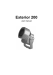
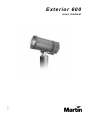
Exterior 600
P/N 35000020
us er ma nu al
©1998, 1999 Martin Professional A/S, Denmark.
All rights reserved. No part of this manual may be
reproduced, in any form or by any means, without
permission in writing from Martin Professional A/S,
Denmark.
Printed in Denmark.
P/N 35000020, Rev. C
table of
CONTENTS
Introduction and Safety
4
Safety precautions ...................................................................................................................4
About this manual ....................................................................................................................4
Lamp Installation
5
Compatible lamps ....................................................................................................................5
Maximum lamp usage..............................................................................................................5
Installing the lamp....................................................................................................................5
Optimizing lamp alignment ......................................................................................................6
AC Power Connection
7
Tapping the power supply........................................................................................................7
Wiring the mains lead ..............................................................................................................8
Data Connection
9
Recommended cable...............................................................................................................9
Building the data link................................................................................................................9
Terminating the link .................................................................................................................9
Installation
10
Location and orientation ........................................................................................................10
Fastener spacing and type ....................................................................................................10
Adjusting pan and tilt .............................................................................................................10
Address, Settings, and Software
11
About the MPBB1 Uploader...................................................................................................11
Setting address and mode.....................................................................................................12
Setting personalities ..............................................................................................................13
Programming MC-X scenes...................................................................................................13
Running a test sequence .......................................................................................................16
Calibrating effects ..................................................................................................................16
Manual control .......................................................................................................................16
Installing software ..................................................................................................................16
Stand-alone Operation
18
Stand-alone settings .............................................................................................................18
General procedure for changing stand-alone settings...........................................................19
Programming a single fixture .................................................................................................19
Synchronizing stand-alone operation ....................................................................................20
Controller Operation
21
Martin RS-485 control............................................................................................................21
DMX-512 control....................................................................................................................21
Operating the lamp ................................................................................................................21
Operating the mechanical effects ..........................................................................................22
Cold weather operation..........................................................................................................22
Operating status ....................................................................................................................23
Basic Service and Maintenance
24
Opening and closing the electronics section .........................................................................24
Replacing fuses .....................................................................................................................24
Changing lenses ....................................................................................................................24
Maintaining the seal...............................................................................................................25
Cleaning the housing .............................................................................................................25
Changing the mains lead .......................................................................................................25
DMX Protocol
26
Troubleshooting
27
Specifications
28
3
section 1
INTRODUCTION AND SAFETY
7KDQNý\RXýIRUýVHOHFWLQJýWKHý0DUWLQý([WHULRUýçííïý7KLVýDXWRPDWHGýOXPLQDLUHýFRPELQHVýDýUDQJHýRIýDUFKLWHFWXUDOýOLJKWLQJ
HIIHFWVýZLWKýH[WUHPHO\ýEULJKWýRXWSXWýLQýDQýDWWUDFWLYHýDOXPLQXPýKRXVLQJýGHVLJQHGýIRUýSHUPDQHQWýRXWGRRUýLQVWDOODWLRQïý
Safety precautions
7KHý([WHULRUýçííýLVýQRWýIRUýGRPHVWLFýXVHïý,WýSUHVHQWVýSRWHQWLDOýULVNVýGXHýWRýHOHFWULFýVKRFNñýKHDWýDQGýXOWUDYLROHWýUDGLDð
WLRQýEXUQVñýODPSýH[SORVLRQñýIDOOVñýKLJKðLQWHQVLW\ýOLJKWñýDQGýILUHïý$ýWKRURXJKýXQGHUVWDQGLQJýRIýWKHýGDQJHUVñýJHQXLQHýFRQð
FHUQýIRUýVDIHW\ñýDQGýDWWHQWLRQýWRýGHWDLOýDUHýUHTXLUHGýWRýSUHYHQWýDFFLGHQWVïý5HDGýWKLVýPDQXDOýEHIRUHýSRZHULQJýRUýLQVWDOOLQJ
WKHýIL[WXUHñýIROORZýWKHýVDIHW\ýSUHFDXWLRQVýOLVWHGýEHORZýDQGýREVHUYHýWKHýZDUQLQJVýLQýWKLVýPDQXDOýDQGýSULQWHGýRQýWKHýIL[ð
WXUHñý DQGý DOZD\Vý GRXEOHý FKHFNý WKHý VDIHW\ý FRQGLWLRQVïý ,Iý\RXý KDYHý TXHVWLRQVý DERXWý KRZý WRý RSHUDWHý WKHý ([WHULRUý çííñ
SOHDVHýFRQWDFWý\RXUý0DUWLQýGHDOHUýIRUýDVVLVWDQFHï
•
ALWAYS disconnect the fixture from AC power and allow it to cool for 20 minutes before:
- Changing the transformer or ballast settings
- Installing or removing the lamp
- Checking or replacing fuses
- Removing any cover or part from the fixture
•
ALWAYS keep combustible materials at least 1 meter (39 inches) away from the fixture. Keep flammable
materials well away from the fixture.
•
For protection against dangerous electric shock, ALWAYS ground (earth) the fixture electrically. Use only
a source of AC power that complies with local building and electrical codes.
•
ALWAYS use at least one fastener in each of the 4 curved mounting slots in the base.
•
ALWAYS refer any service operation not described in this manual to a qualified technician.
•
NEVER illuminate surfaces within 1 meter (39 inches) of the fixture.
•
NEVER place filters or other materials over the lens or front glass plate.
•
NEVER operate the fixture if the ambient temperature (Ta) exceeds 40° C (104° F).
•
NEVER stare directly into the light.
•
NEVER operate the fixture without all lenses and covers installed: an unshielded lamp emits dangerous
UV radiation that can cause burns and eye damage, and it can explode without warning.
•
NEVER modify the fixture or install other than genuine Martin accessories.
About this manual
7KLVýXVHUýPDQXDOýFRYHUVýWKHý([WHULRUýçííýZLWKýYHUVLRQýìïéýVRIWZDUHïý7KHýODWHVWý([WHULRUýçííýQHZVñýGRFXPHQWDWLRQñýDQG
VRIWZDUHýLVýDYDLODEOHýIURPýWKHý0DUWLQý3URIHVVLRQDOýZHEýVLWHýDWýKWWSãîîZZZïPDUWLQïGNï
4
Exterior 600
section 2
LAMP INSTALLATION
7KLVýVHFWLRQýGHVFULEHVýKRZýWRýLQVWDOOýDQGýDGMXVWýDýODPSï
Compatible lamps
7KHý([WHULRUýçííýLVýGHVLJQHGýWRýXVHýWKHýODPSVýOLVWHGýEHORZïý,QVWDOOLQJýRWKHUýODPSVýPD\ýGDPDJHýWKHýIL[WXUHïý
Lamp
Average life
Replace by
Color temp.
Output
P/N
Philips MSD 575
2000 h
2200 h
6000K
78 lm/w
97010202
Philips MSR 575/2
1000 h
1200 h
7200K
85 lm/w
97010201
Osram HSR 575/2
1000 h
1200 h
6000K
85 lm/w
97010200
Maximum lamp usage
7KHýTXDUW]ýEXOEýZHDNHQVýRYHUýWLPHñýVLJQLILFDQWO\ýLQFUHDVLQJýWKHýULVNýRIýODPSýH[SORVLRQïý5HSODFHýWKHýODPSýQRýODWHUýWKDQ
LQGLFDWHGýLQýWKHýWDEOHýDERYHïý
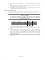
Installing the lamp
WA R N I N G !
Always disconnect the fixture from AC power and allow it to cool before
installing the lamp. For protection against lamp explosion, allow a hot lamp to
cool for at least 2 minutes before removing the access plate.
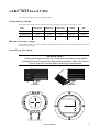
Lamp adjustment
Lamp Installation
5
1.
Isolate the fixture from AC power. If it is hot, allow it to cool for at least 2 minutes before proceeding.
The lamp is under high pressure when hot and can explode: use safety goggles to protect your eyes.
2.
Remove the nut from the long bolt at the top of the fixture and remove the bolt. Loosen the bottom bolt slightly, if necessary, and tilt the rear section back no more than 45° to avoid damaging
the electrical conduit beneath the fixture.
3.
Remove the 4 Allen screws from the lamp access plate. Remove the access plate and the rubber
seal.
4.
Remove the 2 Phillips screws from the lamp-socket assembly. Gently pull out the assembly.
5.
If changing the lamp, remove the old lamp from the socket.
6.
Holding the new lamp by its ceramic base - do not touch the glass - insert it firmly and squarely
into the lamp socket.
7.
Clean the glass bulb with the wipe supplied with the lamp, particularly if your fingers touched the
glass. A clean, lint-free cloth wetted with alcohol may also be used.
8.
Re-insert the lamp assembly. Replace the 2 Phillips screws.
9.
Optimize lamp alignment and then close the fixture as described below.
Optimizing lamp alignment
7KHýODPSýKROGHUýLVýDGMXVWHGýDWýWKHýIDFWRU\âýSUHFLVHýDOLJQPHQWýPD\ýEHýQHFHVVDU\ýGXHýWRýVOLJKWýYDULDWLRQVýEHWZHHQýODPSVï
6
1.
Apply power to the fixture and allow it to reset. Strike the lamp.
2.
Remove the nut from the long bolt at the top of the fixture and remove the bolt. Tilt the rear section back no more than 45° to avoid damaging the electrical conduit beneath the fixture.
3.
Remove the 4 Allen screws from the lamp access plate. Remove the access plate and the rubber
seal.
4.
Center the hot-spot (the brightest part of the beam) by turning the 3 adjustment screws one at a
time to move the hot-spot diagonally across the beam. If there is no hot-spot, adjust until the
light is even.
5.
To reduce the hot-spot, pull the lamp back towards you by turning all three screws clockwise 1/4turn at a time until the light is evenly distributed.
6.
If the light is brighter around the edge than it is in the center, or if light output is low, the lamp is
too far back in the reflector. Move the lamp forward by turning the adjustments screws counterclockwise 1/4-turn at a time until the light is bright and evenly distributed.
7.
Check the condition of the lamp access seal. Replace with a new one (P/N 20620050) if the seal
is torn, cracked or brittle.
8.
Place the seal on the back of the lamp access plate. Insert the 4 Allen screws through the plate
and install. Tighten the Allen screws with a torque of 6 N.m (4.5 Ft-Lbs). With this torque, the
seal will be compressed by about one-third.
9.
Tilt the rear section into position and replace the long bolt and lock nut.
Exterior 600
section 3
A C PO W E R C O N N E C T I O N
7KLVýVHFWLRQýGHVFULEHVýKRZýWRýWDSýWKHýSRZHUýVXSSO\ýIRUýWKHýORFDOý$&ýYROWDJHýDQGýIUHTXHQF\ñýDQGýKRZýWRýFRQQHFWýWKH
([WHULRUýçííýWRý$&ýSRZHUïý
'RýQRWýFRQQHFWýWKHý([WHULRUýçííýWRýDQýHOHFWULFDOýGLPPHUýV\VWHPãýGRLQJýVRýFDQýGDPDJHýWKHýHOHFWURQLFVï
IMPORTANT!
Check voltage and frequency settings before applying power.
Ta p p i n g t h e p o w e r s u p p l y
Ve r i f y s e t t i n g s
7KHýYROWDJHýDQGýIUHTXHQF\ýVHWWLQJVýPXVWýPDWFKýWKHýORFDOý$&ýSRZHUýVXSSO\üý7KHýIDFWRU\ðVHWýSRZHUýVXSSO\ýWDSSLQJVýDUH
SULQWHGýRQýWKHýVHULDOýQXPEHUýODEHOýRQýWKHýEDFNýSODWHïý2SHUDWLQJýDWýWKHýLQFRUUHFWýSRZHUýVHWWLQJýFDQýUHVXOWýLQýSRRUýOLJKW
RXWSXWñýJUHDWO\ýUHGXFHGýODPSýOLIHñýRYHUKHDWLQJýDQGýGDPDJHýWRýWKHýIL[WXUHïý,IýWKHýVHWWLQJýGRHVýQRWýPDWFKý\RXUýORFDOý$&
YROWDJHýDQGýIUHTXHQF\ñýWKHQýWKHýSRZHUýVXSSO\ýPXVWýEHýUHWDSSHGýDVýGHVFULEHGýEHORZï
Ch a ngi ng vo ltag e a nd f req ue ncy se tt in gs
Local AC Supply
Frequency
50 Hz
Transformer
Ballast
Voltage
Setting
Terminal
Setting
Terminal
200-210 V
210 V
4
200 V / 50 Hz
7
210-220 V
210 V
4
230 V / 50 Hz
10
220-235 V
230 V
6
230 V / 50 Hz
10
235-240 V
230 V
6
245 V / 50 Hz
12
240-260 V
250 V
8
245 V / 50 Hz
12
200-217 V
210 V
4
208 V / 60 Hz
4
217-240 V
230 V
6
227 V / 60 Hz
7
60 HZ
WA R N I N G !
Disconnect the fixture from AC power before removing any cover.
1.
Make sure the Exterior 600 is isolated from AC power. Remove the
10 Allen screws from the rear cover plate. Pull off the plate and seal.
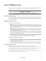
2.
Find the row in the above table with the local AC frequency and
voltage. Follow the row to the right to find the correct transformer
and ballast tappings. For example, with a local AC supply of
230V, 50 Hz, the correct transformer tapping is terminal 6 and
the correct ballast tapping is terminal 10.
3.
To tap the transformer, move the 2 BROWN wires to the correct
terminal. Terminals are identified on the transformer in front of
the connection tabs.
4.
To tap the ballast, move the single BROWN wire to the correct terminal.
5.
Check the condition of the seal. Replace with a new one (P/N 20600020) if the seal is torn,
cracked or brittle.
AC Power Connection
Ballast
Transformer
7
6.
Insert the Allen screws through all holes in the cover and seal. Place the cover firmly against the
body.
7.
Adjust the straight sides of the seal so that they stick out a little bit, just enough so that you can
feel the seal when you run a finger across the joint.
8.
Cross-tighten the cover bolts. The correct torque for these bolts is 6 N.m (4.5 Ft-Lbs). With this
torque, the seal will be compressed by about one-third.
Wiring the mains lead
7KHý([WHULRUýçííýLVýHTXLSSHGýZLWKýDýêðPHWHUýõìíýIWïôýOHQJWKýRIýêðFRQGXFWRUýìïèýPPëýõaìçý$:*ôýHOHFWULFDOýFDEOHýIRU
FRQQHFWLRQýWRýWKHý$&ýSRZHUýVXSSO\ïý6HHý¦&KDQJLQJýWKHýPDLQVýOHDG§ýRQýSDJH ëèýLIýDQRWKHUýOHDGýLVýUHTXLUHGï
WARNING!
For protection from dangerous electric shock, the fixture must be grounded
(earthed). The AC mains supply shall be fitted with a fuse or circuit breaker
and ground-fault protection.
8
Wire (EU)
Wire (US)
Pin
Marking
Screw (US)
brown
black
live
“L”
yellow or brass
blue
white
neutral
“N”
silver
yellow/green
green
ground
green
1.
Verify that the power supply is tapped for the local AC voltage and frequency.
2.
Verify that the feed cable is undamaged and rated for the current requirements of all connected
devices.
3.
To connect the Exterior 600 to an electrical outlet or cable, install an appropriate grounding-type
cord cap on the mains lead. Connect the yellow/green wire to ground (earth), the brown wire to
live (hot), and the blue wire to neutral. The above table shows some possible pin identification
schemes; if the pins are not clearly identified, or if you have any doubts about proper installation,
consult a qualified electrician.
4.
Consult a qualified electrician if the Exterior 600 is to be connected directly to building wiring.
There shall be a switch in the circuit to turn power off when the fixture is not in use or is being
serviced.
Exterior 600
section 4
DATA CONNECTION
7KLVýVHFWLRQýGHVFULEHVýKRZýWRýFRQQHFWýIL[WXUHVýWRýDýFRQWUROOHUýDQGýRWKHUýGHYLFHVñýDQGýKRZýWRýWHUPLQDWHýWKHýGDWDýOLQNïý)RU
GDWDýFRQQHFWLRQñýWKHý([WHULRUýçííýKDVýWZRýéïèýPHWHUýõìèýIWïôýWUDLOLQJýFDEOHVýZLWKýORFNLQJýêðSLQý;/5ýFRQQHFWRUVïý
D ATA P I N - O U T
Pin 1: shield Pin 2: signal - (cold) Pin 3: signal + (hot)
Recommended cable
8VHýRQO\ýFDEOHýGHVLJQHGýIRUý56ðéåèýGHYLFHVïý7KHýFDEOHýVKDOOýEHýVXLWDEOHýIRUýRXWGRRUýXVHïý,WýVKDOOýKDYHýORZýFDSDFLWDQFH
DQGýDýFKDUDFWHULVWLFýLPSHGDQFHýRIýåèýWRýìèíýRKPVïý,WýVKDOOýEHýHOHFWULFDOO\ýVKLHOGHGýDQGýKDYHýDWýOHDVWýìýWZLVWHGýSDLUýRI
ZLUHVïý7KHýPLQLPXPýZLUHýVL]HýLVýíïëýPPýõëéý$:*ôýIRUýUXQVýXSýWRýêííýPHWHUVýõìíííýIWïôýDQGýíïêëëýPPýõëçý$:*ôýIRU
UXQVýXSýèííýPHWHUVýõìçéíýIWïôïý
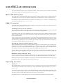
Building the data link
To c o n n e c t t h e c o n t r o l l e r
1.
DMX controllers: Connect a data cable to the controller’s data output. If the cable has a 3-pin male
plug and the controller has a 5-pin female socket, use a 5-pin male to 3-pin female adaptor cable (P/N
11820005) or replace the 3-pin plug with a 5-pin plug. The pin-out is the same for 3-pin and 5-pin
plugs. Pins 4 and 5 are not used.
Martin RS-485 protocol controllers (3032): First, connect a 3-pin “swapper” cable (P/N 11820006) to
the controller’s data output; then, connect a regular data cable to the swapper cable. A swapper cable
connects pin 2 to pin 3 and pin 3 to pin 2.
2.
If the controller is located in a central position between 2 or more fixtures, you may split the link
into branches using a splitter such as the Martin 4-Channel Opto-Isolated RS-485 Splitter/Amplifier.
Do not use a “Y” connector to split the link.
3.
Lead the data cable from the controller to the first fixture. Plug the cable into the fixture cable
with the male XLR connector. If the cable from the controller has a 5-pin plug, replace it with a 3pin plug or insert a 5-pin male to 3-pin female adaptor cable (P/N 11820005).
To c o n n e c t a d d i t i o n a l f i x t u r e s
1.
Connect the output (female) of the fixture closest to the controller to the input (male) of the next fixture.
(If connecting to another type of fixture with reversed-polarity (pin 3 cold), such as the PAL 1200, insert
a swapper cable between the two fixtures.)
2.
Continue connecting fixtures output to input. Up to 32 fixtures may be connected on a serial link.
If more fixtures are required, use another controller output, if available, or an RS-485 amplifier.
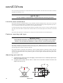
Te r m i n a t i n g t h e l i n k
/LQNýWHUPLQDWLRQýLVýDFKLHYHGýE\ýLQVHUWLQJýDýìëíýRKPýUHVLVWRUýDFURVVýWKHýVLJQDOýòýõKRWôýDQGýVLJQDOýðýõFROGôýZLUHVâýLWýLV
LPSRUWDQWýIRUýWURXEOHðIUHHýFRPPXQLFDWLRQïý,IýDýVSOLWWHUýLVýXVHGñýWHUPLQDWHýHDFKýEUDQFKýRIýWKHýOLQNï
7KHýHDVLHVWýZD\ýWRýWHUPLQDWHýWKHýOLQNýLVýWRýLQVHUWýDýPDOHýWHUPLQDWLRQýSOXJýLQWRýWKHýGDWDýRXWSXWýFDEOHýRIýWKHýODVWýIL[WXUHïý$
WHUPLQDWLRQýSOXJýLVýVLPSO\ýDQý;/5ýFRQQHFWRUýZLWKýDýìëíýRKPýUHVLVWRUýVROGHUHGýDFURVVýSLQVýëýDQGýêï
3HUPDQHQWýOLQNýWHUPLQDWLRQýFDQýEHýDFKLHYHGýE\ýSODFLQJýDýìëíýRKPýUHVLVWRUýDFURVVýWKHýWHUPLQDOVýIRUýWKHýKRWýDQGýFROG
GDWDýZLUHVýRQýWKHýFRQQHFWLRQýEORFNýLQVLGHýWKHýHOHFWURQLFVýVHFWLRQï
Data Connection
9
section 5
INSTALLATION
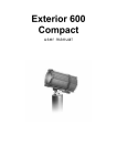
7KLVýVHFWLRQýEULHIO\ýGHVFULEHVýKRZýWRýDQFKRUýWKHý([WHULRUýçííïý7KHý([WHULRUýçíí©VýEDVHýDOORZVýWKHýIL[WXUHýWRýPDQXDOO\
EHýSDQQHGýèíƒýDQGýWLOWHGýòîðýéíƒïý
NOTICE!
It is the installer’s responsibility to determine the anchoring method.
Location and orientation
7KHý([WHULRUýçííýPD\ýEHýLQVWDOOHGýRXWGRRUVñýLQýDQ\ýRULHQWDWLRQïý,WýVKDOOýEHýORFDWHGýDWýOHDVWýìýPHWHUýõêäýLQïôýDZD\ýIURP
WKHýVXUIDFHýWRýEHýLOOXPLQDWHGýDQGýDQ\ýFRPEXVWLEOHýPDWHULDOVïý7KHýDOXPLQXPýKRXVLQJýUHDFKHVýWHPSHUDWXUHVýXSýWRýåíƒý&
õìæçƒý)ôãýWKHýIL[WXUHýVKRXOGýQRWýEHýORFDWHGýZKHUHýLWýFDQýDFFLGHQWDOO\ýEHýWRXFKHGï
7RýDFKLHYHýWKHýIXOOýWLOWýUDQJHñýWKHýIL[WXUHýPXVWýEHýLQVWDOOHGýRQýDýSHGHVWDOýDWýOHDVWýìëýFPýõéïæýLQôýORQJïý7RýDFKLHYHýWKHýIXOO
SDQýUDQJHñýWKHýIL[WXUHýPXVWýEHýDQFKRUHGýZLWKýéýIDVWHQHUVýWKDWýFDQýEHýORRVHQHGñýVSDFHGýDWýäíƒýLQWHUYDOVýDVýGHVFULEHG
EHORZïý
7KHý([WHULRUýçííýUHTXLUHVýIUHHðFLUFXODWLQJýDLUýIRUýFRROLQJïý'RýQRWýORFDWHýWKHýIL[WXUHýLQýDQýXQYHQWLODWHGýVSDFHï
Fastener spacing and type
WARNING!
Verify that the structure can bear at least 10 times the weight of all installed
fixtures. Use at least one fastener in each of the 4 curved mounting slots.
7KHýIL[WXUHýLVýGHVLJQHGýWRýEHýDQFKRUHGýZLWKýIRXUýìíýPPýõêîåýLQïôýEROWVïý$GGLWLRQDOýEROWVýPD\ýEHýXVHGýEXWýWKHýSDQýUDQJH
ZLOOýEHýUHGXFHGïý(YHQO\ýVSDFHýWKHýEROWVýDWýäíƒýLQWHUYDOVñýFHQWHUHGýRQýDýìæíýPPýõçýDQGýììîìçýLQïôýFLUFOHñýVRýWKDWýRQHýEROW
SDVVHVýWKURXJKýHDFKýFXUYHGýVORWýLQýWKHýIRRWýRIýWKHýEDVHïý
7KHýVSHFLILFýKDUGZDUHýZLOOýGHSHQGýRQýWKHýLQVWDOODWLRQïý&RQVXOWýDýTXDOLILHGýHQJLQHHUýWRýGHWHUPLQHýDýVXLWDEOHýDQFKRULQJ
PHWKRGýDQGýWRýYHULI\ýWKDWýWKHýVWUXFWXUHýFDQýVDIHO\ýEHDUýDWýOHDVWýìíýWLPHVýWKHýIL[WXUH©VýZHLJKWïý,QýJHQHUDOñýXVHýKLJKýTXDOLW\
FRUURVLRQýUHVLVWDQWýIDVWHQHUVýVXFKýDVý]LQFðSODWHGýVWHHOñýJUDGHýåïåýRUýEHWWHUñýWRJHWKHUýZLWKýHLWKHUýVHOIðORFNLQJýQXWVýRUýQXWV
DQGýORFNðZDVKHUVï
Adjusting pan and tilt
10
1.
To adjust the pan, loosen the anchor bolts slightly so that the fixture can turn. Manually adjust the pan
position and retighten the bolts.
2.
To adjust the tilt, loosen both tilt locks on either side of the base. Position the fixture and
retighten the tilt lock nuts.
Exterior 600
section 6
ADDRESS, SETTINGS, AND SOFTWARE
7KLVýVHFWLRQýGHVFULEHVýKRZýWRýVHWýWKHýIL[WXUHýDGGUHVVýDQGýRWKHUýVHWWLQJVñýFDOLEUDWHýHIIHFWVñýUXQýDýWHVWýURXWLQHñýDQGýLQVWDOO
VRIWZDUHýXSGDWHVïý7KHýHIIHFWVýRIýSHUVRQDOLW\ýVHWWLQJVýDUHýGHVFULEHGýLQýVHFWLRQýåïý
About the MPBB1 Uploader
6HWWLQJVýDUHýFKDQJHGýXVLQJýDý0DUWLQý03%%ìýXSORDGHUýWKDWýKDVýEHHQýORDGHGýZLWKýWKHý([WHULRUýçíí©VýFRQWUROýVRIWZDUHñ
ZKLFKýLVýDYDLODEOHýIRUýGRZQORDGýIURPýWKHý0DUWLQýZHEýVLWHñýDQGýFRQQHFWHGýWRýWKHýIL[WXUHýRUýWKHýGDWDýOLQNïý 7KHýVRIWZDUH
YHUVLRQýORDGHGýLQýWKHýIL[WXUHýDQGýWKHý03%%ìýPXVWýEHýWKHýVDPHïý1RWHãý6RIWZDUHýIRUýWKHýVWDQGDUGý([WHULRUýçííýõILOHV
QDPHGý¦(;çíí;;;ï08ë§ôýLVýQRWýWKHýVDPHýDVýIRUýWKHý([WHULRUýçííý&RPSDFWýõILOHVýQDPHGý¦(;çí&;;;ï08ë§ôïý%H
VXUHýWRýLQVWDOOýWKHýFRUUHFWýVRIWZDUHýLQýWKHýXSORDGHUýEHIRUHýXVHïý
7KHýXSORDGHUýKDVýëýPRGHVãýVLQJOHðIL[WXUHñýZKHUHýLWýVHQGVýLQVWUXFWLRQVýRQO\ýWRýWKHýIL[WXUHýDWýDýVSHFLILFýDGGUHVVâýDQGýDOOð
IL[WXUHVñýZKHUHýLWýVHQGVýWRýDOOýVDPHðW\SHýIL[WXUHVýRQýWKHýOLQNïý&RPPXQLFDWLRQýLVýRQHðZD\âýIURPýWKHýXSORDGHUýWRýWKHýIL[ð
WXUHñýVRýWKHUHýLVýQRýZD\ýWRýUHDGýWKHýDGGUHVVýRUýVHWWLQJVïý7KHUHýLVñýKRZHYHUñýDýXWLOLW\ýIRUýILQGLQJýIL[WXUHýDGGUHVVHVïý3OHDVH
VHHýWKHý03%%ìýPDQXDOýIRUýDGGLWLRQDOýLQVWUXFWLRQVï
To s e t f i x t u r e s v i a t h e s e r i a l l i n k
7Rý FKDQJHý VHWWLQJVý RQý DOOý ([WHULRUýçííVý DWý WKHý VDPHý WLPHñý FRQQHFWý WKHý 03%%ìý WRý WKHýGDWDý OLQNý DQGý XVHýDOOðIL[WXUHV
PRGHïý,Iý\RXýVHWýWKHýDGGUHVVýLQýDOOðIL[WXUHVýPRGHñýDOOý([WHULRUýçííVýZLOOýEHýVHWýWRýWKHýVDPHýDGGUHVVï
7RýFKDQJHýWKHýVHWWLQJVýRIýDQýLQGLYLGXDOýIL[WXUHýYLDýWKHýVHULDOýOLQNñýXVHýVLQJOHðIL[WXUHýPRGHïý7KHýIL[WXUH©VýDGGUHVVýPXVWýEH
NQRZQýDQGýQRýRWKHUýIL[WXUHýPD\ýKDYHýWKHýVDPHýDGGUHVVïý2WKHUZLVHñýLIý\RXýFDQýDSSO\ýSRZHUýRQO\ýWRýWKHýIL[WXUHý\RXýZDQWýWR
VHWýDQGý\RXýFDQýWXUQýRIIýDOOýRWKHUVñýXVHýDOOðIL[WXUHVýPRGHãýRQO\ýWKHý([WHULRUýçííýWKDWýLVýSRZHUHGýRQýZLOOýEHýVHWï
To s e t a f i x t u r e v i a d i r e c t c o n n e c t i o n
$QýLQGLYLGXDOýIL[WXUHýFDQýDOVRýEHýVHWýE\ýFRQQHFWLQJýLWVýGDWDýLQSXWýõPDOHôýGLUHFWO\ýWRýWKHý03%%ì©VýRXWSXWïý7RýDYRLGýVHWð
WLQJýRWKHUý([WHULRUýçííVýRQýWKHýOLQNñýGLVFRQQHFWýWKHýIL[WXUH©VýGDWDýRXWSXWïý
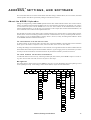
Navigation
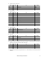
7KHýVHWWLQJVýPHQXýLVýVKRZQýEHORZïý3UHVVýWKHý03%%ì©VýDUURZýNH\VýWRýVFUROOýWKURXJKýWKHýPHQXïý3UHVVý>(QWHU@ýWRýVHOHFW
LWHPVýRUý>0HQX@ýWRýHVFDSHïý$ýIHZýVHWWLQJVñýVXFKýDVýIL[WXUHýDGGUHVVñýUHTXLUHýDQýH[WUDýFRQILUPDWLRQï
36(7
G$GU
0$GU
$G-
&$/
567
G#2)
/#21
76(4
()63
)
63(&
6$
7,0(
G/2)
(1$E
+285
35(4
0,1
G,0
&2/
&<$1
0$*
<(/
)526
=220
/$03
G5(6
/,7(
(1$E
/(9
/R))
0#2)
$/21
$//
<#2)
$872
G,0
$6+7
&<$1
6&87
0$*
())E
<(/
&2/
%($0
=220
6+87
7,0(
(1$E
6757
6723
0&0;
35(5
:$,7
35(6
)$G(
35(7
&0,1
35(8
&0$;
35(9
00,1
35(:
00$;
<0,1
<0$;
)526
=220
0$67
Address, Settings, and Software
11
Setting address and mode
7KHýIL[WXUHýDGGUHVVýDQGýFRQWUROýPRGHýPXVWýEHýVHOHFWHGýEHIRUHýWKHý([WHULRUýçííýZLOOýUHVSRQGýFRUUHFWO\ýWRýDýFRQWUROOHUïý
7KHýIL[WXUHýDGGUHVVñýDOVRýNQRZQýDVýWKHýVWDUWýFKDQQHOñýLVýWKHýILUVWýFKDQQHOýXVHGýWRýUHFHLYHýLQVWUXFWLRQVýIURPýWKHýFRQWUROOHUï
7KHý([WHULRUýçííýUHTXLUHVýåýFKDQQHOVýLQý'0;ýPRGHýìýDQGýäýFKDQQHOVýLQý'0;ýPRGHýëïý,WýXVHVýëýFKDQQHOVýLQý0DUWLQ
PRGHïý7KHýFRQWUROýPRGHVýDUHýGHVFULEHGýRQýSDJH ëìï
)L[WXUHýDGGUHVVHVýPD\ýEHýVHWýLQýDQ\ýRUGHUïý7ZRý([WHULRUýçííVýPD\ýVKDUHýWKHýVDPHýDGGUHVVâýKRZHYHUñýWKH\ýZLOOýUHFHLYH
WKHýVDPHýLQVWUXFWLRQVýDQGýLQGHSHQGHQWýFRQWUROýZLOOýQRWýEHýSRVVLEOHïý
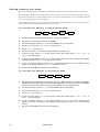
To s e t m o d e a n d a d d r e s s i n s i n g l e - f i x t u r e m o d e
),;7
G0;
FXUUHQW
DGGUHVV
6,1*
VHWWLQJV
1.
Plug the serial link into the “DMX/RS-485 OUT” socket on the MPBB1.
2.
Apply power to the Exterior 600 and the MPBB1.
3.
Use the arrow keys to select FI XT from the MPBB1 menu. Pressý[Enter].
4.
Select the current mode, dMX or MA RT. Pressý[Enter].
5.
Select SIN G. Pressý[Enter].
6.
Scroll to the fixture’s current DMX or Martin address. Pressý[Enter].
7.
To set the mode, select P SET. Press [Enter]. Select the desired mode - DM X1 , DMX2 , or
MA RT - and press [Enter].
8.
To set a new DMX address, select dAd r . Press [Enter]. Scroll to the new address. Press [Enter].
Press [Enter] again when SUR E is displayed to confirm.
9.
To set a new Martin address, select M Adr . Press [Enter]. Scroll to the new address. Press
[Enter]. Press [Enter] again when S URE is displayed to confirm.
10. Disconnect the MPBB1 and reconnect the serial link.
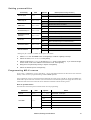
To s e t m o d e a n d a d d r e s s i n a l l - f i x t u r e s m o d e
),;7
12
G0;
$//
VHWWLQJV
1.
Plug the data input cable (male) of the fixture to set into the “DMX/RS-485 OUT” socket on the MPBB1.
Disconnect the data output cable from the serial link. Alternatively, connect the serial link to the MPBB1
at any convenient point and make sure that power is applied only to the desired fixture.
2.
Use the arrow keys to select FI XT from the MPBB1 menu. Pressý[Enter].
3.
Select the current mode, dMX or MA RT. Pressý[Enter].
4.
Select ALL . Pressý[Enter].
5.
To set the mode, select P SET. Press [Enter]. Select the desired mode - DM X1 , DMX2 , or
MA RT - and press [Enter].
6.
To set an address, select dA dr , for a DMX address, or MA dr , for a Martin address. Press
[Enter]. Scroll to the new address. Press [Enter]. Press [Enter] again when SURE is displayed to
confirm.
7.
Disconnect the MPBB1 and reconnect the serial link.
Exterior 600
Setting personalities
Personality
Effects speed
DMX lamp off
DMX reset
Automatic lamp on
Path
Normal, full speed operation.
SAFE
Reduced speed operation.
ON
Enable DMX lamp off command.
OFF
Disable DMX lamp off command.*
ON
Enable DMX reset command.
OFF
Disable DMX reset command.*
ON
Lamp strikes within 90 seconds of power on.
OFF
Strike lamp with controller command.
ON
Enable automatic protocol detection.
OFF
Disable automatic protocol detection.
ON
Effect wheels turn the shortest direction.*
OFF
Effect wheels always turn same direction.*
ON
Shutter “helps” dimmer black out.
OFF
Shutter not affected by dimmer commands.
ON
Enable feedback on effect wheels.
OFF
Disable feedback on effect wheels.
SPEC/dLOF
SPEC/dRES
SPEC/ALON
SPEC/AUTO
Shortcuts
SPEC/SCUT
Effects feedback
FAST
EFSP
Automatic protocol
detection
Automatic shutter
Effect (Default settings shaded.)
Options
SPEC/ASHT
SPEC/EFFb
óý6HWWLQJýPD\ýEHýRYHUULGGHQýYLDý'0;ïý6HHýWKHýSURWRFROýIRUýGHWDLOVï
1.
Select FI XT from the MPBB1 menu. Pressý[Enter] to continue or [Menu] to escape.
2.
Select the mode, dMX or MA RT. Press [Enter].
3.
Select single-fixture ( S ING ) or all-fixtures (ALL ) mode. Press [Enter]. If you selected singlefixture mode, scroll to the address of the fixture to set. Pressý[Enter].
4.
Navigate to the personality setting to adjust. Pressý[Enter].
5.
Select the desired option. Pressý[Enter].
Programmin g MC-X scenes
6HYHQýVFHQHVýðýFRPELQDWLRQVýRIýFRORUVýDQGýHIIHFWVýðýFDQýEHýSURJUDPPHGýDQGýVWRUHGýLQýWKHý([WHULRUýçíí©VýHOHFWURQLF
PHPRU\ïý7KHVHýVFHQHVýDUHýSURJUDPPHGýXVLQJýDý0DUWLQý03%%ìýXSORDGHUï
2QFHýSURJUDPPHGñýVFHQHVýDUHýH[HFXWHGýXVLQJýWKHý0DUWLQý0&ð;ýUHPRWHýFRQWUROïý7KHý0&ð;ñýZKLFKýVHQGVý'0;ýFRPð
PDQGVýZLWKýDýVSHFLDOýVWDUWðFRGHýRQýFKDQQHOýìñýDOVRýKDVýIXQFWLRQVýWRýEODFNRXWýWKHýOLJKWýDQGýWRýHQJDJHýWKHý([WHULRUýçíí©V
VWDQGðDORQHýPRGHïý3OHDVHýUHIHUýWRýWKHý0&ð;ýXVHUýPDQXDOýIRUýLQIRUPDWLRQýDERXWýH[HFXWLQJýVFHQHVï
Scene parameters
7KHýWDEOHýEHORZýVKRZVýWKHýRSWLRQVýDYDLODEOHýIRUý0&ð;ýVFHQHýSURJUDPPLQJïýýý
Parameter
Dimmer
Color filter
Cyan
Path
d IM
C OL
C YAN
Options
Effect
0 - 255
Full closed Æ full open
W HIT
Open
C TC
CTC filter
R Ed
Red
G REE
Green
B LUE
Blue
0 - 255
White Æ Cyan
Address, Settings, and Software
13
Parameter
Path
Options
Effect
Magenta
M AG
0 - 255
White Æ Magenta
Yellow
YEL
0 - 255
White Æ Yellow
ON
Frost on
Frost
F ROS
O FF
Frost off
0 - 255
Wide Æ narrow
ON
Lamp power on
O FF
Lamp power off
Zoom
Z OOM
Lamp
L AMP
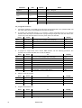
To p r o g r a m s c e n e s
1.
Connect the serial link, or the DMX input of the fixture to be programmed, to the uploader’s DMX / RS
485 output. Apply power to the uploader first and then the fixtures.
2.
To program all connected fixtures, or to program a single connected fixture at an unknown
address, follow the steps in the table below. If programming a single fixture with this method, disconnect any other identical fixtures from AC power and/or the data link.
Press
Times
Display
as needed
go to top of menu (display stops changing)
varies
up / down
as needed
select fixture menu
FIXT
Enter
1
enter menu
dMX
Enter
1
enter menu
ALL
Enter
1
enter menu
PSET
3.
To program a single fixture with a known DMX address, use the following procedure. The
uploader user manual describes how to find an address.
Press
Menu
Times
as needed
To
go to top of menu (display stops changing)
Display
varies
up / down
as needed
select fixture menu
FIXT
Enter
1
enter menu
dMX
Enter
1
enter menu
ALL
down
1
select single fixture mode
SING
Enter
1
enter address selection menu
001
up / down
as needed
scroll to the fixture’s DMX address
varies
Enter
1
set uploader to fixture’s DMX address
PSET
4.
Select a scene to program.
Press
Times
up / down
as needed
select MC-X menu
MC-X
Enter
1
enter menu
PRE1
up / down
as needed
select scene from 1 to 7
varies
Enter
1
enter effect menu
dIM
5.
14
To
Menu
To
Display
Program the dimmer level.
Press
Times
up / down
as needed
To
select dimmer level menu
Display
dIM
Enter
1
enter menu
0
up / down
as needed
adjust dimmer level
0-255
Enter
1
save setting and continue
dIM
Exterior 600
6.
Program the color wheel color.
Press
Times
To
Display
up / down
as needed
select color wheel menu
COL
Enter
1
enter menu
WHIT
up / down
as needed
select color
varies
Enter
1
save setting and continue
COL
7.
Set CMY color.
Press
Times
up / down
as needed
select cyan menu
CYAN
Enter
1
enter menu
0
up / down
as needed
set cyan level
0-255
Enter
1
save setting and continue
CYAN
down
1
select magenta menu
MAG
Enter
1
enter menu
0
up / down
as needed
set magenta level
0-255
Enter
1
save setting and continue
MAG
down
1
select yellow menu
YEL
Enter
1
enter menu
0
up / down
as needed
select yellow level
0-255
Enter
1
save setting and continue
YEL
8.
To
Display
Turn frost on/off.
Press
Times
To
Display
up / down
as needed
select frost menu
FROS
Enter
1
enter menu
OFF
up / down
as needed
turn frost on or off
ON/OFF
Enter
1
save setting and continue
FROS
9.
Set zoom.
Press
Times
To
Display
up / down
as needed
select zoom menu
ZOOM
Enter
1
enter menu
0
up / down
as needed
select zoom level
0-255
Enter
1
save setting and continue
ZOOM
10. Program a lamp off command in one scene if you want to control lamp power with the MC-X.
Otherwise, set the lamp command to ON in each scene.
Press
Times
To
Display
down
1
select lamp menu
LAMP
Enter
1
enter menu
ON
up / down
as needed
program lamp on or lamp off command
ON/OFF
Enter
1
save setting and continue
LAMP
11. Repeat steps as necessary to program scenes 1 to 7. When finished, turn off and disconnect the
uploader.
Address, Settings, and Software
15
Running a test sequence
7KHýWHVWýVHTXHQFHýDOORZVý\RXýWRýWHVWýWKHýIL[WXUHýZLWKRXWýDýFRQWUROOHUïý
1.
Select FI XT from the MPBB1 menu. Pressý[Enter].
2.
Select the mode, dMX or MA RT. Press [Enter].
3.
Select single-fixture ( S ING ) or all-fixtures (ALL ) mode. Press [Enter]. If you selected singlefixture mode, scroll to the address of the fixture to test. Pressý[Enter].
4.
Navigate to TS EQ . Press [Enter]. Press [Enter] again to confirm.
Calibrating effects
7KHýFDOLEUDWLRQýPHQXýDOORZVý\RXýWRýDGMXVWýWKHýHIIHFWVýIRUýWRWDOýXQLIRUPLW\ýEHWZHHQýIL[WXUHVãýLWýLVýQRWýDýVXEVWLWXWHýIRU
PHFKDQLFDOýDGMXVWPHQWñýZKLFKýVKDOOýRQO\ýEHýSHUIRUPHGýE\ýDýTXDOLILHGýWHFKQLFLDQïý
1.
Select FI XT from the MPBB1 menu. Pressý[Enter] to continue or [Menu] to escape.
2.
Select the mode, dMX or MA RT. Press [Enter].
3.
Select SIN G . Pressý[Enter]. Scroll to the fixture address. Pressý[Enter].
4.
Navigate to CA L . Pressý[Enter].
5.
Select effect to calibrate: dimmer ( d O F ), cyan (C OF ), magenta (M O F ), or yellow (Y O F ).
Press [Enter].
6.
Adjust from 1 to 255. Press >Enter@ýto save the calibration.
Manual control
7KHýDGMXVWPHQWýPHQXýõ$G-ôýSURYLGHVýPDQXDOýFRQWUROýIRUýPDNLQJýPHFKDQLFDOýDGMXVWPHQWVýDQGýLVýIRUý VHUYLFHýWHFKQLð
FLDQVïý7KHýPHQXýSURYLGHVýIXQFWLRQVýWRýUHVHWýWKHýIL[WXUHýõRST ôñýWXUQýRQýDQGýRIIýWKHýODPSýõL ý ON ñý Lo FF ôñýDQGýPRYH
DOOýHIIHFWVýWRýWKHLUýOPENñýSPOSýõVHQVRUôñýDQGýAPOSýõDGMXVWPHQWôýSRVLWLRQVñýWRJHWKHUýõALL ôýRUýLQGLYLGXDOO\ïý
Installing software
7KHýODWHVWýFRQWUROýVRIWZDUHýIRUýWKHý([WHULRUýçííýLVýDYDLODEOHýIURPý\RXUý0DUWLQýGHDOHUýDQGýWKHý0DUWLQýZHEýVLWHýDWýKWWSãîî
ZZZïPDUWLQïGNïý
6RIWZDUHýLVýXSORDGHGýWRýWKHý([WHULRUýçííýXVLQJýDQýXSORDGHUýVXFKýDVýWKHý0DUWLQý03%%ìïý3OHDVHýUHIHUýWRýWKHýXSORDGHU
PDQXDOýIRUýLQVWUXFWLRQVýRQýSUHSDULQJýWKHýXSORDGHUýIRUýXVHï
Normal upload
1.
Connect the MPBB1 to the fixture or serial link as if connecting a controller.
2.
Power up the fixtures and allow them to reset. Turn on the MPBB1.
3.
Use the arrow keys to select U PLd from the MPBB1 menu. Pressý[Enter] to continue or [Menu]
to escape.
4.
Select DMX or Martin protocol. If the fixtures are set for auto protocol detection, either protocol
may be used. If not, the protocol must match the fixture PS ET setting.
5.
Press [Enter]. The LEDs on the Exterior 600s are steady yellow to indicate an upload is in
progress. When the upload is complete, the MPBB1 displays dO NE and the fixtures reset.
Boot mode upload
,IýWKHýGDWDýLVýFRUUXSWHGýGXULQJýWUDQVPLVVLRQñýDýFKHFNðVXPýHUURUýRFFXUVýWKDWýFDXVHVýWKHýIL[WXUHýWRýVZLWFKýWRýERRWýPRGHýLQ
SUHSDUDWLRQýIRUýDýVHFRQGýXSORDGýDWWHPSWïý([HFXWHýDýERRWðPRGHýXSORDGýDVýGHVFULEHGýLQýWKHýXSORDGHUýPDQXDOïý
,IýDQýXSORDGýDWWHPSWýLVýLQWHUUXSWHGñýWKHýIL[WXUHýPXVWýEHýSRZHUHGýRIIýIRUýDWýOHDVWýìíýVHFRQGVýEHIRUHýDýVHFRQGýXSORDGýFDQ
EHýDWWHPSWHGïý:KHQýWKHýIL[WXUHýLVýSRZHUHGýRQñýDýFKHFNðVXPýHUURUýRFFXUVýWKDWýFDXVHVýLWýWRýVZLWFKýWRýERRWýPRGHýLQýSUHSDð
UDWLRQýIRUýWKHýVHFRQGýXSORDGýDWWHPSWïý6HOHFWýERRWýPRGHýXSORDGýRQýWKHýXSORDGHUï
,IýWKHýVRIWZDUHýLQýPHPRU\ýLVýFRUUXSWHGñýVRIWZDUHýFDQýEHýLQVWDOOHGýXVLQJýWKHý¦KDUGðERRW§ýVHWWLQJñýZKLFKýLVýHQDEOHGýE\
PRYLQJýDýMXPSHUýRQýWKHýFLUFXLWýERDUGïý7KLVýXSORDGýSURFHGXUHýLVýDOVRýXVHGýWRýLQVWDOOýVRIWZDUHýLIýLWýLQFOXGHVýDQýXSGDWHýRI
WKHýERRWýVHFWRUïý
16
Exterior 600
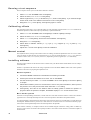
1.
Disconnect the fixture from AC power. Open the electronics section as described on page 24.
2.
On the circuit board, move jumper PL121 to pins 1
and 2 (hard boot setting) as shown.
3.
Connect the fixture’s data input (male) to the MPBB1.
Apply power to the uploader first and then to the fixture.
È PIN 1 È
PL104
PL121
normal setting
È PIN 1 È
PL104
PL121
hard boot setting
4.
Select U PLd from the MPBB1 menu and press
[Enter]. Select boo t . Pressý[Enter] to start the upload. When the upload is finished, the MPBB1
displays dO NE and the fixture resets with the new software.
5.
Disconnect the fixture from the electricity, move the jumper back to the normal setting, and close
the electronics section as described.
Address, Settings, and Software
17
section 7
STAND-ALONE OPERATION
7KLVýVHFWLRQýGHVFULEHVýKRZýWRýRSHUDWHýWKHý([WHULRUýçííýZLWKRXWýDýFRQWUROOHUýLQýVWDQGðDORQHýõ6$ôýPRGHýLQýZKLFKýWKHýIL[ð
WXUHýH[HFXWHVýUDQGRPýFRORUýFKDQJHVýDWýVHWýLQWHUYDOVýDQGýVSHHGVýDWýDýVHWýWLPHýDQGîRUýOLJKWýOHYHOïý$Qý03%%ìý8SORDGHUýLV
XVHGýWRýSURJUDPýWKHýVWDQGðDORQHýVHWWLQJVïý3OHDVHýVHHý¦$ERXWýWKHý03%%ìý8SORDGHU§ýRQýSDJH ììï
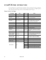
Stand-alone settings
SA setting
Options
Effect
Clock set: hour
TIME/HOUR
0-23
Sets the current hour.
Clock set: minute
TIME/MIN
0-59
Sets the current minute.
SA on/off
SA/ENAb
ON-OFF
Enables/disable other SA settings. Turn
SA off on slave fixtures.
Light sensor on/off
SA/LITE/ENAb
ON-OFF
Toggles light-level control.
Light level
SA/LITE/LEV
0-255
Sets the light trigger level. 0 is darkest,
255 is brightest. When setting, light
switches on/off at current level.
Clock on/off
SA/TIME/ENAb
ON-OFF
Toggles clock control.
Start hour
SA/TIME/STRT/HOUR
0-23
Sets the start hour.
Start minute
SA/TIME/STRT/MIN
0-59
Sets the start minute.
Stop hour
SA/TIME/STOP/HOUR
0-23
Sets the stop hour.
Stop minute
SA/TIME/STOP/MIN
0-59
Sets the stop minute.
Wait time
SA/WAIT
1 sec60 min
Sets the time between color changes.
Set wait time = fade time for continuous
change.
Fade time
SA/FAdE
0-60
Sets the fade time in seconds.
Minimum cyan
Minimum magenta
Minimum yellow
SA/CMIN
SA/MMIN
SA/YMIN
0-255
Sets the minimum amount of each color
to use in the random color. Must be less
than or equal to maximum.
Maximum cyan
Maximum magenta
Maximum yellow
SA/CMAX
SA/MMAX
SA/YMAX
0-255
Sets the maximum amount of each color
to use in the random color. Must be
greater than or equal to the minimum.
Frost on/off
SA/FROS
ON-OFF
Toggles the frost filter.
Zoom level
SA/ZOOM
0-255
Sets the zoom level. 0 = full flood.
Master on/off
SA/MAST
ON-OFF
Toggles master signal transmission.
1
Same color on master and slave.
13
Master CMY mix maps to slave MYC.
25
Master CMY mix maps to slave YCM.
37
Master CMY mix maps to slave MCY.
49
Master CMY mix maps to slave CYM.
61
Master CMY mix maps to slave YMC.
Slave address
18
Path
dAdr
Exterior 600
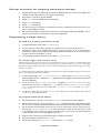
General procedure for changing stand-alone settings
1.
Plug the fixture’s data input cable (male) into the 3-pin “DMX/RS-485 OUT” socket on the MPBB1. Disconnect the data output cable if it is connected to other fixtures.
2.
Apply power to the fixture and the MPBB1.
3.
Select FIX T from the MPBB1 menu. Pressý[Enter].
4.
Select dMX . Pressý[Enter].
5.
Select ALL . Pressý[Enter].
6.
Use the arrow keys to navigate to the desired menu item. Press [Enter] to select the item or submenu, or press [Menu] to escape.
7.
When all the settings have been made, disconnect the data input cable from the MPBB1. Reconnect the output cable to the data link or next fixture if applicable.
Programmin g a single fixture
To e n a b l e o r d i s a b l e s t a n d - a l o n e m o d e
1.
To enable stand-alone mode, switch SA /ENA b to ON .
2.
Turn the fixture off. Stand-alone operation is enabled when you turn the fixture back on.
3.
Stand-alone mode can be disabled temporarily by turning the fixture off, or, if connected to a
controller, by sending control signals. Stand-alone operation resumes when the fixture has been
turned off and then turned back on again.
4.
To permanently disable stand-alone mode, switch S A/E NAb to OFF.
To s e t t h e t r i g g e r a n d i n t e r n a l c l o c k
6WDQGðDORQHýRSHUDWLRQýFDQýEHýVHWýIRUýDýWLPHýRIýGD\ñýXVLQJýWKHýEXLOWðLQýFORFNñýRUýIRUýDýOLJKWýOHYHOñýXVLQJýWKHýEXLOWðLQýOLJKW
VHQVRUïý,IýERWKýWKHýFORFNýDQGýWKHýOLJKWýVHQVRUýDUHýXVHGñýRSHUDWLRQýVWDUWVñýZLWKLQýWKHýWLPHVýVHWñýDVýVRRQýDVýLWýLVýGDUNHUýWKDQ
WKHýOLJKWðOHYHOýVHWWLQJïý2SHUDWLRQýVWRSVýDWýWKHýVWRSýWLPHýRUýZKHQýWKHýDPELHQWýOLJKWýLVýEULJKWHUýWKDQýWKHýOLJKWðOHYHOýVHWWLQJñ
ZKLFKHYHUýFRPHVýILUVWïý
7RýDYRLGýIDOVHýWULJJHULQJýE\ýVXGGHQýOLJKWýFKDQJHVñýIRUýH[DPSOHýIURPýDXWRPRELOHýKHDGOLJKWVñýWKHýOLJKWýOHYHOýPXVWýUHPDLQ
DERYHýRUýEHORZýWKHýWULJJHUýWKUHVKROGýIRUýèýPLQXWHVï
1.
To use the light trigger, set SA /LIT E/E NAb to ON . Then navigate to SA/ LIT E/L EV and
select a trigger level from 0 (darkest) to 25 5 (brightest). The light toggles on and off as you scroll past
the current light level.
2.
To use the clock, set S A/T IME /EN Ab to ON . Navigate to S A/TI ME/ STR T/H OUR and
select the start hour from 0 (midnight) to 2 3 (11 PM), then set SA/ TIME /ST RT/ MIN from
0 to 59 . Set the stop hour and minute with SA /TIM E/S TOP /HO UR and SA/ TIM E/
ST OP/ MIN .
3.
To set the correct time, set TI ME/ HOUR to the correct hour, using 24-hour time, and set
TI ME/ MIN to the correct minute.
To p r o g r a m s t a n d - a l o n e e f f e c t s
1.
Set a wait time from 1 second to 1 hour using S A/W AIT. This is the time a color is applied.
2.
Set the fade time from 0 to 60 seconds using SA/ FAdE . The fade time is the time it takes to change
from one color to another. If the fade time and wait time are the same, the colors change continuously.
3.
Set the minimum and maximum amount of cyan to use in the random color mix from 0 (none) to
255 (full) with SA /CM IN and SA/ CMA X . Note: The minimum value must be less than or equal
to the maximum value. Setting both values to 0 excludes the color from the mix and setting them
to 255 causes the color to be fully applied all the time.
4.
Similarly, set the minimum and maximum levels of magenta and yellow.
5.
Apply the frost filter if desired with S A/F ROS .
6.
Set the zoom level using SA /ZO OM . 0 = full flood and 25 5 = full spot.
Stand-alone Operation
19
Syn chro nizing stan d-alone operation
6\QFKURQRXVýVWDQGðDORQHýRSHUDWLRQýRIýVHYHUDOý([WHULRUýçííVýPD\ýEHýDFKLHYHGýE\ýOLQNLQJýWKHPýWRJHWKHUýDQGýXVLQJýWKH
PDVWHUîVODYHýIXQFWLRQýLQýZKLFKýRQHýXQLWýðýRQO\ýðýWUDQVPLWVýFRQWUROýVLJQDOVýWRýWKHýRWKHUVïý6WDQGDUGý([WHULRUýçííVýDUHýFRPð
SDWLEOHýZLWKý&RPSDFWýPRGHOVýLQýPDVWHUîVODYHýFRQILJXUDWLRQïý,IýERWKýW\SHVýDUHýXVHGñýVHOHFWýRQHýRIýWKHýVWDQGDUGý([WHULRU
çííVýWRýEHýWKHýPDVWHUýIL[WXUHýLIý\RXýZDQWýWRýXVHýWKHýIURVWýDQGîRUý]RRPýRSWLRQVïý
To l i n k a n d t e r m i n a t e f i x t u r e s
6\QFKURQRXVýRSHUDWLRQýUHTXLUHVýWKDWýWKHýIL[WXUHVýEHýFRQQHFWHGýRQýDýGDWDýOLQNïý
7HUPLQDWLQJýWKHýOLQNýRQýERWKýHQGVýLVýUHFRPPHQGHGýZKHQýWKHUHýLVýQRýFRQWUROOHUïý7RýWHUPLQDWHýWKHýILUVWýIL[WXUHñýSOXJýDýêð
SLQýIHPDOHý;/5ýSOXJýZLWKýDýìëíýRKPýUHVLVWRUýVROGHUHGýDFURVVýSLQVýëýDQGýêýLQWRýLWVýLQSXWýõPDOHôýFDEOHïý7RýWHUPLQDWHýWKH
ODVWýIL[WXUHñýSOXJýDýêðSLQýPDOHý;/5ýSOXJýZLWKýDýìëíýRKPýUHVLVWRUýDFURVVýSLQVýëýDQGýêýLQWRýLWVýRXWSXWýõIHPDOHôýFDEOHïý
To s e l e c t a n d p r o g r a m t h e m a s t e r f i x t u r e
1RýPRUHýWKDQýRQHýIL[WXUHýPD\ýEHýWKHýPDVWHUïý$Q\ýIL[WXUHýRQýWKHýOLQNñýKRZHYHUñýUHJDUGOHVVýRIýLWVýSRVLWLRQñýPD\ýEHýWKH
PDVWHUñýVRýVHOHFWýWKHýIL[WXUHýWKDWýLVýHDVLHVWýWRýDFFHVVïý
1.
Program the master fixture as described above for single fixtures.
2.
Switch S A/M AST to O N . This causes the master fixture to transmit control signals to the
slaves.
To p r o g r a m s l a v e f i x t u r e s
$ýVODYHýIL[WXUHýPXVWýEHýVHWýXSýLQý'0;ýPRGHýìýRUýëñýDXWRPDWLFýSURWRFROýGHWHFWLRQýõA UTO ôýPXVWýEHýWXUQHGýRIIñýDQGýLW
PXVWýKDYHýRQHýRIýWKHý'0;ýDGGUHVVHVýOLVWHGýEHORZïý6HHý¦7RýVHWýPRGHýDQGýDGGUHVVýLQýDOOðIL[WXUHVýPRGH§ýRQýSDJH ìëýLI
\RXýQHHGýWRýFKDQJHýWKHýVHWWLQJVïý
7KHý'0;ýDGGUHVVýGHWHUPLQHVýKRZýWKHýVODYH©VýFRORUýUHODWHVýWRýWKHýPDVWHU©VýFRORUïý7KHýVODYH©VýVWDQGðDORQHýVHWWLQJVýPXVW
EHýGLVDEOHGýVRýLWýFDQýFRQWUROOHGýE\ýWKHýPDVWHUýIL[WXUHïý
20
1.
Connect the input of the slave fixture to the output of the MPBB1. Disconnect the fixture’s output from
the serial link.
2.
Using the MPPB1, switch SA /EN Ab to O FF. This disables the other stand-alone settings.
3.
Navigate to dA dr and set the slave address to 1, 13, 25, 37, 49, or 61. No other addresses may
be used for slave fixtures. Set the address to 1 to have the slave execute the same color as the
master. Set the address to 13, 25, 37, 49, or 61 to have the slave execute a different color. The
color relationship for each address is shown in the table of stand-alone settings.
4.
Disconnect the MPBB1 and reconnect the data link.
5.
Turn the fixture off. The stand-alone settings take effect when the fixture is turned back on.
Exterior 600
section 8
CONTROLLER OPERATION
7KLVýVHFWLRQýGHVFULEHVýWKHý([WHULRUýçíí©VýFRQWUROýPRGHVñýHIIHFWVñýDQGýWKHýSHUVRQDOLW\ýRSWLRQVýDYDLODEOHýIRUýFXVWRPL]LQJ
WKHPïý7KHý/('ýGLVSOD\ýDQGýFROGýZHDWKHUýRSHUDWLRQýDUHýDOVRýFRYHUHGïý
Mar tin RS-485 con trol
7KHý([WHULRUýçííýLVýFRQWUROODEOHýZLWKýWKHý0DUWLQýêíêëýFRQWUROOHUïý7KRXJKýWKHý([WHULRUýçííýLVýQRWýLPSOHPHQWHGýLQýWKH
êíêëýVRIWZDUHñýLWýPD\ýEHýVHWýXSýLQýWKHýFRQWUROOHUýDVýDý0$&ýçííï8VHýWKHýEHDPðVKDSHUýìýFRQWUROýWRýRSHUDWHýWKHý]RRPïý
)RUýWKHýIL[WXUHýWRýUHVSRQGñýHLWKHUýWKHýSURWRFROýVHWWLQJýPXVWýEHýVHWýWRý0DUWLQýõP SET ý!ýM ART ôñýRUýDXWRPDWLFýSURWRFRO
GHWHFWLRQýPXVWýEHýHQDEOHGýõS PEC ý!ýA UTO ý!ýO N ôïý
DMX-512 control
7KHý([WHULRUýçííýLVýFDQýEHýFRQWUROOHGýE\ýDQ\ý86,77ý'0;ðèìëýõìääíôýSURWRFROýFRQWUROOHUïý7KHýFRQWUROOHUýPXVWýVHQGýD
VWDUWýFRGHýRIýíýDWýWKHýEHJLQQLQJýRIýHYHU\ýSDFNHWïý
Tr a c k i n g v e r s u s v e c t o r c o n t r o l
7KHý([WHULRUýçííýKDVýëý'0;ýFRQWUROýPRGHVãýWUDFNLQJýDQGýWUDFNLQJîYHFWRUýFRQWUROïý7UDFNLQJîYHFWRUýFRQWUROýFRQWDLQVýDOO
IHDWXUHVýRIýERWKýPRGHVýDQGýLVýUHFRPPHQGHGýLIýWKHUHýLVýURRPýIRUýWKHýDGGLWLRQDOý'0;ýFKDQQHOï
:LWKý WUDFNLQJý FRQWUROñý IDGHVý DUHý SURJUDPPHGý XVLQJý WKHý FRQWUROOHU©Vý IDGHý WLPHïý 7KHý FRQWUROOHUý GLYLGHVý WKHý IDGHý LQWR
VPDOOýSLHFHVýWKDWýWKHýIL[WXUHý¦WUDFNVï§ý7KHý([WHULRUýçííýKDVýDýGLJLWDOýILOWHUýDOJRULWKPýWKDWýDYHUDJHVýVHYHUDOýXSGDWHVýWR
HQVXUHýVPRRWKýPRYHPHQWï
9HFWRUýFRQWUROýSURYLGHVýDýZD\ýWRýSURJUDPýIDGHVýRQýFRQWUROOHUVýZLWKRXWýSURJUDPPDEOHýIDGHýWLPHVïý:LWKýYHFWRUýFRQWUROñ
LQVWHDGýRIýEUHDNLQJýXSýWKHýPRYHPHQWýLQWRýPDQ\ýVPDOOýSRVLWLRQVñýWKHýFRQWUROOHUýVHQGVýRQHýSRVLWLRQýYDOXHýDORQJýZLWKýD
VSHHGýYDOXHýWKDWýLVýSURJUDPPHGýRQýDýVHSDUDWHýFKDQQHOïý9HFWRUýFRQWUROýPD\ýSURYLGHýVPRRWKHUýIDGHVýWKDQýWUDFNLQJýFRQð
WUROýZLWKýVRPHýFRQWUROOHUVñýSDUWLFXODUO\ýRQýYHU\ýVORZýIDGHVï
Switching control modes (mode 2 only)
5HIHUýWRýWKHý'0;ýSURWRFROýIRUýFKDQQHOýäñýWKHýVSHHGýFKDQQHOñýRQýSDJH ëçïý7RýHQDEOHýWUDFNLQJýFRQWUROýLQýWUDFNLQJîYHFWRU
PRGHýõPRGHýëôñýVHWýFKDQQHOýäýWRý¦7UDFNLQJ§ýõ'0;ýíýðýëôïý7RýVZLWFKýWRýYHFWRUýFRQWUROñýVHWýWKHýFRQWUROOHU©VýIDGHUýõLI
DSSOLFDEOHôýWRýíýDQGýVHWýDýVSHHGýXVLQJýWKHý'0;ýYDOXHVýIURPýêýWRýëéèïý7UDFNLQJýFRQWUROýFDQýDOVRýEHýHQDEOHGýZLWKýRU
ZLWKRXWýVKRUWFXWVñýUHJDUGOHVVýRIýWKHýSHUVRQDOLW\ýVHWWLQJñýZLWKýWKHý'0;ýYDOXHVýIURPýëéçýWRýëèìï
<RXýPD\ýVZLWFKýEHWZHHQýWUDFNLQJýDQGýYHFWRUýFRQWUROñýEXWý\RXýFDQQRWýXVHýWKHPýERWKýDWýWKHýVDPHýWLPHïý:KHQýXVLQJ
WUDFNLQJýFRQWUROñýVHWýWKHýVSHHGýFKDQQHOýWRýDýWUDFNLQJýYDOXHïý:KHQýXVLQJýYHFWRUýFRQWUROñýVHWýWKHýFRQWUROOHUýIDGHýWLPHýWRýíï
Blackout speed (mode 2 only)
7KHý ([WHULRUý çííý IHDWXUHVý Dý VSHFLDOý ¦EODFNRXWý VSHHG§ý IRUýWKHý FRORUýZKHHOý DQGý EHDPý VKDSHUïý :KHQý ¦%ODFNRXWý ZKLOH
PRYLQJýLVýVHOHFWHG§ýRQýFKDQQHOýäñýWKHýVKXWWHUýFORVHVýZKLOHýWKHýFRORUýZKHHOýDQGîRUýEHDPýVKDSHUýPRYHVýDWýIXOOýVSHHGïý
%ODFNRXWýVSHHGýGRHVýQRWýDSSO\ýWRýWKHýGLPPHUñý&0<ýZKHHOVñýRUýWKHý]RRPýPRGXOHïý,Iý'0;ýYDOXHVýIURPýëèëýðýëèèýDUH
VHOHFWHGñýWKHVHýHIIHFWVý¦VQDS§ýDWýIXOOýVSHHGýEXWýWKHýVKXWWHUýUHPDLQVýRSHQï
Operating the lamp
Lamp on
:LWKýWKHýGHIDXOWýVHWWLQJñýWKHýODPSýUHPDLQVýRIIýXQWLOýDý¦ODPSýRQ§ýFRPPDQGýLVýVHQWýIURPýWKHýFRQWUROOHUïý7RýKDYHýWKHýODPS
VWULNHýDXWRPDWLFDOO\ýZLWKLQýäíýVHFRQGVýRIýSRZHULQJýRQñýVZLWFKýWKHý$XWRPDWLFý/DPSý2QýSHUVRQDOLW\ýWRýRQýõSPE C ý!
ALO N ý!ýON ôïý
$ýODUJHýSHDNýRIýHOHFWULFýFXUUHQWýLVýGUDZQýIRUýDQýLQVWDQWýZKHQýVWULNLQJýDýGLVFKDUJHýODPSïý6WULNLQJýPDQ\ýODPSVýDWýRQFH
PD\ýFDXVHýDýYROWDJHýGURSýODUJHýHQRXJKýWRýSUHYHQWýODPSVýIURPýVWULNLQJýDQGîRUýWULSýFLUFXLWýEUHDNHUVïý:KHQýVWULNLQJýPXOð
WLSOHýODPSVñýSURJUDPýDýVHTXHQFHýWKDWýVWULNHVýODPSVýRQHýDWýDýWLPHýDWýèýVHFRQGýLQWHUYDOVïý
,Iý$XWRPDWLFý/DPSý2QýLVýHQDEOHGñýWKHUHýLVýDýGHOD\ýRIýXSýWRýäíýVHFRQGVýWKDWýLVýGHWHUPLQHGýE\ýWKHýIL[WXUHýDGGUHVVï
Controller Operation
21
Lamp off
7KHýODPSýFDQýEHýWXUQHGýRIIýIURPýWKHýFRQWUROOHUýE\ýVHQGLQJýDý¦ODPSýRII§ýFRPPDQGýRQýFKDQQHOýìïý,IýWKHý'0;ý/DPSý2II
SHUVRQDOLW\ýLVýRIIýõSPE C ý!ýdL OF ý!ýO FF ôñýWKHýFRPPDQGýRQO\ýZRUNVýLIýHDFKýRIýWKHý&0<ýFKDQQHOVýõêñýéñýDQGýèôýLV
VHWýWRýDý'0;ýYDOXHýIURPýëêíýWRýëêëï
$IWHUýEHLQJýWXUQHGýRIIñýWKHýODPSýPXVWýFRROýIRUýDWýOHDVWýåýPLQXWHVýEHIRUHýLWýFDQýEHýWXUQHGýEDFNýRQïý¦/DPSýRQ§ýFRPPDQGV
VHQWýZLWKLQýåýPLQXWHVýRIýDý¦ODPSýRII§ýFRPPDQGýDUHýVWRUHGýDQGýWKHQýH[HFXWHGýDIWHUýWKHýWLPHýKDVýHODSVHGïý
Operating the mechanical effects
7KHýPHFKDQLFDOýHIIHFWVýUHVHWýWRýWKHLUý¦KRPH§ýSRVLWLRQýZKHQýWKHý([WHULRUýçííýLVýSRZHUHGýRQïý7KH\ýFDQýDOVRýEHýUHVHW
IURPýWKHýFRQWUROOHUýRQýFKDQQHOýìïý,IýWKHý'0;ý5HVHWýSHUVRQDOLW\ýLVýRIIýõ63(&ý!ýG5(6ý!ý2))ôñýWKHýUHVHWýFRPPDQGýRQO\
ZRUNVýLIýHDFKýRIýWKHý&0<ýFKDQQHOVýLVýVHWýWRýDý'0;ýYDOXHýIURPýëêíýWRýëêëïý
$QýRQðWKHðIO\ýSRVLWLRQýFRUUHFWLRQýV\VWHPýDXWRPDWLFDOO\ýFRUUHFWVýWKHýSRVLWLRQýRIýWKHýHIIHFWýZKHHOVïý7KLVýIHDWXUHýFDQýEH
GLVDEOHGýE\ýWXUQLQJýHIIHFWVýIHHGEDFNýRIIýõ63(&ý!ý())Eý!ý2))ôñýEXWýWKLVýLVýQRWýUHFRPPHQGHGï
Color wheel
7KHýFRORUýZKHHOýKDVýUHGñýJUHHQñýDQGýEOXHýGLFKURLFýFRORUýILOWHUVýSOXVýDýèçíí.ýWRýêéíí.ýFRORUýFRUUHFWLRQýILOWHUýDQGýRSHQ
ZKLWHïý,WýPD\ýEHýXVHGýWRJHWKHUýZLWKý&0<ýFRORUýPL[LQJýWRýLQFUHDVHýFRORUýVDWXUDWLRQïý7KHýZKHHOýVFUROOVýFRQWLQXRXVO\ñ
DOORZLQJýIRUýVSOLWðFRORUýHIIHFWVñýRUýLQýIXOOýVWHSVïý,WýDOVRýURWDWHVýFRQWLQXRXVO\ýLQýERWKýGLUHFWLRQVýDWýGLIIHUHQWýVSHHGVï
7KHý6KRUWFXWVýõSPEC ý!ýS CUT ôýVHWWLQJýGHWHUPLQHVýZKHWKHUýWKHýZKHHOýWDNHVýWKHýVKRUWHVWýSDWKýWRýWKHýQH[WýSRVLWLRQýRU
WXUQVýLQýRQHýGLUHFWLRQýRQO\ïý7KHýVHWWLQJýPD\ýEHýRYHUULGGHQýRQýWKHýVSHHGýFKDQQHOýLQýPRGHýëïý
6HWWLQJýWKHýFRORUýVSHHGýWRý¦EODFNRXW§ýLQýPRGHýëýFDXVHVýWKHýVKXWWHUýWRýEODFNýRXWýWKHýOLJKWýZKLOHýWKHýZKHHOýPRYHVï
CMY subtractive color mixing
7KHý&0<ýFRORUýPL[LQJýV\VWHPýLVýEDVHGýRQýJUDGXDWHGýF\DQñýPDJHQWDñýDQGý\HOORZýFRORUýILOWHUVïý$ýFRQWLQXRXVýUDQJHýRI
PL[HGýFRORUVýPD\ýEHýDFKLHYHGýE\ýYDU\LQJýWKHýDPRXQWýRIýHDFKýILOWHUýIURPýíýWRýìííøïý1RWHýWKDWýPL[LQJýêýFRORUVýUHVXOWV
LQýDýORVVýRIýOLJKWýðýWKHýOLJKWýLVýEODFNHGýRXWýZKHQýDOOýêýFRORUVýDUHýIXOO\ýDSSOLHGïý)RUýPD[LPXPýEULJKWQHVVñýPL[ýRQO\ýëýFROð
RUVýDWýDýWLPHï
7KHý6KRUWFXWVýõS CUT ôýVHWWLQJýGHWHUPLQHVýZKHWKHUýWKHýZKHHOVýWDNHýWKHýVKRUWHVWýSDWKýWRýWKHýQH[WýSRVLWLRQýRUýWXUQýLQýRQH
GLUHFWLRQýRQO\ïý7KHýVHWWLQJýPD\ýEHýRYHUULGGHQýRQýWKHýVSHHGýFKDQQHOýLQýYHFWRUýPRGHïý
Dimmer
7KHýPHFKDQLFDOýGLPPHUýSURYLGHVýVPRRWKñýKLJKðUHVROXWLRQýìííýSHUFHQWýGLPPLQJïý
Shutter
7KHýKLJKðVSHHGýPHFKDQLFDOýVKXWWHUýRSHQVýDQGýFORVHVýWKHýOLJKWýLQVWDQWO\ïý/LJKWýFDQýEHýIODVKHGýDWýXSýWRýåý+]ýDQGýWKHUHýLV
Dý'0;ðFDOODEOHýUDQGRPýVWUREHýIXQFWLRQïý
,IýWKHýDXWRýVKXWWHUýIXQFWLRQýLVýHQDEOHGýõS PEC ý!ýA SHT ý!ýO N ôñýWKHýVKXWWHUñýZKLFKýLVýIDVWHUýWKDQýWKHýGLPPHUñýDXWRPDWð
LFDOO\ýFORVHVýZKHQýWKHýGLPPHUýUHFHLYHVýDýFRPPDQGýWRýFORVHý¦LQVWDQWO\ñ§ýWRýSURYLGHýIDVWHUýEODFNRXWVï
Zoom
7KHý)UHVQHOýOHQVýPD\ýEHýGULYHQýIRUZDUGVýRUýEDFNZDUGVýWRýYDU\ýWKHýVL]HýRIýWKHýEHDPïý7KHý]RRPýIXQFWLRQýKDVýOLWWOHýHIIHFW
ZLWKýWKHýRSWLRQDOýçèƒýGLIIXVHUýOHQVýLQVWDOOHGïý
Beam shaper and frost
7KHýEHDPýVKDSHUýIODWWHQVýDQGýZLGHQVýWKHýEHDPýLQWRýDQýRYDOñýZKLFKýURWDWHVýäíƒïý
7KHýIURVWýILOWHUýVRIWHQVýWKHýEHDPïý$VýLWýLVýRQýWKHýVDPHýZKHHOýDVýWKHýEHDPýVKDSHUñýWKHýëýHIIHFWVýFDQQRWýEHýFRPELQHGï
7KHýEHDPýVKDSHUýDQGýIURVWýKDYHýOLWWOHýHIIHFWýZKHQýXVHGýZLWKýWKHýRSWLRQDOýçèƒýGLIIXVHUýOHQVï
Cold weather operation
:KHQýWKHýWHPSHUDWXUHýLVýH[SHFWHGýWRýIDOOýEHORZýIUHH]LQJñýWKHýHOHFWURQLFVýPXVWýEHýNHSWýZDUPýE\ýOHDYLQJýWKHýIL[WXUHýRQï
7KHýODPSñýKRZHYHUñýPD\ýEHýVZLWFKHGýRIIïý
22
Exterior 600
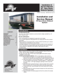
Operating status
8QGHUý QRUPDOý RSHUDWLRQñý WKHý /('ý GLVSOD\ý LQGLFDWHVý WKHý VWDWXVý RIý WKH
PHFKDQLFDOýHIIHFWVýDQGýWKHýFRQWUROýGDWDïý7ZRýVWHDG\ýJUHHQý/('VýLQGLFDWHV
SURSHUýRSHUDWLRQïý$ýUHGýRUýXQOLWý/('ýLQGLFDWHVýDQýHUURUï
6SHFLDOýFRQGLWLRQVýDUHýDOVRýLQGLFDWHGïý%RWKý/('VýIODVKý\HOORZýZKLOHýWKH
IL[WXUHýLVýUHVHWWLQJïý'XULQJýDýVRIWZDUHýXSORDGñýERWKý/('VýDUHýVWHDG\ý\HOð
ORZïý
LED 1
LED 2
SENSOR
7KHý/('VýIODVKýRIIýIRUýDýEULHIýLQVWDQWýDWýUHJXODUýLQWHUYDOVïý7KLVýLVýWRýSUHYHQWýIDOVHýUHDGLQJVýZKHQýWKHýOLJKWýVHQVRUýVDPð
SOHVýWKHýDPELHQWýOLJKWýOHYHOïý
S u m m a r y, ýL E D 1
•
•
•
•
Steady green: Fixture ready, mechanical effects OK.
Flashing red and green: Fixture ready with one or more errors. Contact a service technician.
Flashing yellow: Reset in progress.
Steady yellow: Software upload in progress.
S u m m a r y, L E D 2
•
•
•
•
•
Off: No data.
Steady green: Data OK.
Steady red: Invalid data.
Flashing yellow: Reset in progress.
Steady yellow: Software upload in progress.
Controller Operation
23
section 9
BASIC SERVICE AND MAINTENANCE
7KLVýVHFWLRQýGHVFULEHVýDGGLWLRQDOýVHUYLFHýSURFHGXUHVïý3URFHGXUHVýQRWýGHVFULEHGýVKDOOýEHýUHIHUUHGýWRýDýTXDOLILHGýWHFKQLFLDQï
WA R N I N G !
Disconnect the fixture from AC power before removing any cover.
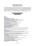
Openin g and closing th e electronics section
1.
Disconnect the fixture from AC power.
2.
To open, remove the 10 Allen screws from the rear cover plate.
Pull off the plate and seal.
Ballast
Transformer
3.
Before closing, check the condition of the seal. Replace with a
new one (P/N 20600020) if the seal is torn, cracked or brittle.
Fuse
4.
To close, insert the Allen screws through all holes in the cover
and seal. Place the cover firmly against the body. Adjust the
straight sides of the seal so that they stick out a little bit, just
enough so that you can feel the seal when you run a finger across the joint.
5.
Cross-tighten the cover bolts with a torque of 6 N.m (4.5 Ft-Lbs). With this torque, the seal will
be compressed by about one-third.
Replacing fuses
7KHý([WHULRUýçííýKDVýéýIXVHVïý7KHýPDLQýIXVHýLVýORFDWHGýLQýDýIXVHýKROGHUýLQVLGHýWKHýHOHFWURQLFVýVHFWLRQñýWRýWKHýOHIWýRIýWKH
EDOODVWïý7KHýIXVHVýIRUýHDFKýRIýWKHýêýORZðYROWDJHýSRZHUýVXSSOLHVýDUHýORFDWHGýRQýWKHýSULQWHGýFLUFXLWýERDUGï
1.
Make sure the Exterior 600 is isolated from AC power. Open the electronics section.
2.
To remove the printed circuit board from the fixture, remove 2 screws from the aluminum bracket
and pull the board out.
3.
Locate and replace the defective fuse with one of the same size and rating.
4.
Close the electronics section before applying power.
Changing lenses
7KHUHýDUHýêýIURQWýOHQVHVýIRUýWKHý([WHULRUýçííïý7KHýVWDQGDUGýOHQVýSURYLGHVýDýEHDPýDQJOHýRIýëëƒýWRýêåƒñýZKHUHýWKHýHGJHýRI
WKHýEHDPýLVýWKHýFLUFOHýZLWKýìíýSHUFHQWýRIýWKHýFHQWHUýLQWHQVLW\ïý7KHýRSWLRQDOýQDUURZýDQJOHýOHQVýSURYLGHVýDýEHDPýDQJOHýRI
ìåƒýWRýëèƒïý7KHýRSWLRQDOýZLGHýDQJOHýGLIIXVHUý¦OHQV§ýSURYLGHVýDýçèƒýEHDPýDQJOHïý
24
1.
Disconnect the fixture from AC power. Remove the front aluminum
plate - not the glass - by removing the 10 Allen screws.
2.
The lens assembly is secured by 3 brackets along the rim.
Remove 2 of the brackets and slide the lens out.
3.
If replacing the narrow or standard Fresnel lens with the wide
angle diffuser lens, completely remove all 3 rim brackets and
store them together with the lens. The dffuser is secured with
the rim brackets (P/N 17200280) that are included in the kit.
4.
Position the new lens on the zoom module. Replace the rim
brackets.
5.
Before closing, check the condition of the seal. Replace with a new one (P/N 20600020) if the
seal is torn, cracked or brittle.
6.
To replace the front plate, insert the Allen screws through all holes in the plate and seal. Place
the plate firmly against the body. Adjust the straight sides of the seal so that they stick out a little
bit, just enough so that you can feel the seal when you run a finger across the joint.
Exterior 600
7.
Cross-tighten the Allen screws with a torque of 6 N.m (4.5 Ft-Lbs). With this torque, the seal will
be compressed by about one-third.
Maintaining the seal
7KHý([WHULRUýçííýKDVýDQý,3ýUDWLQJýRIýçèãýLWýLVýSURWHFWHGýDJDLQVWýGXVWýDQGýFDQýZLWKVWDQGýORZýSUHVVXUHýZDWHUýMHWVïý7RýPDLQð
WDLQýSURWHFWLRQýDJDLQVWýGXVWýDQGýZDWHUãý
1.
Replace any seal that becomes brittle or shows visible signs of wear.
2.
Verify that seals are flush with, or protrude slightly above, the surface of the aluminum covers.
3.
Verify that cable pass-through fittings are tightened both to the casing and the cable.
4.
Tighten the end plates and the lamp access plate with a torque of 6 N.m (4.5 Ft-Lbs). With this
torque, the seals will be compressed by about one-third.
Cleaning the housing
7KHý([WHULRUýçíí©VýDOXPLQXPýKRXVLQJýFDQýEHýFOHDQHGýZLWKýPLOGýGHWHUJHQWVýVXFKýDVýWKRVHýIRUýZDVKLQJýFDUVïý
1.
Disconnect the fixture and allow it to cool.
2.
Visually check that the seals are in good condition.
3.
Rinse off loose dirt with a garden hose or low pressure water spray.
4.
Wash the aluminum using a mild detergent and a soft brush or sponge. Do not use abrasive
cleaners.
5.
Rinse.
Changing the mains lead
7KHý PDLQVý OHDGý PD\ý EHý UHSODFHGý ZLWKý Dý ORQJHUý RUý KHDYLHUý JDXJHý FDEOHý LIý QHFHVVDU\ïý 7KHý SDVVðWKURXJKý ILWWLQJý VHDOV
DURXQGýFDEOHVýIURPýêïèýWRýäïåýPPýõèîêëýðýêîåýLQïôýLQýGLDPHWHUïý
1.
Make sure the Exterior 600 is isolated from AC power. Remove the 10 Allen screws from the rear cover
plate. Pull off the plate and seal.
2.
Remove the 2 screws from the aluminum circuit-board bracket and pull the circuit board out.
3.
Unplug the power cable’s brown lead from the back of the main fuse holder. Remove the green/
yellow lead from the grounding bolt located above the ballast. Disconnect the blue lead from the
connection block located in front of the transformer.
4.
Loosen the large outer nut on the mains lead pass-through fitting. Cut zip ties as necessary and
pull the mains lead out of the fixture. Transfer the outer pass-through nut to the new cable and
then insert the new cable through the fitting. Pull the cable into the fixture and cut to 52 cm (20
in.) from the inside of the pass-through.
5.
Remove 28 cm (11 in.) of outer insulation. Lead the cable between the fuse holder and housing.
6.
Install a 6.3 mm (1/4 in.) insulated female spade terminal on the live lead (brown), and plug the
lead into the back of the main fuse holder.
7.
Install a ring terminal on the ground lead (green/yellow), place the terminal on the grounding bolt
over the ballast, and replace the nut.
8.
Strip 6 mm (1/4 in.) of insulation from the neutral lead (blue) and screw the lead into the neutral
terminal of the connection block in front of the transformer.
9.
Replace the printed circuit board. Bundle the wires together as before with zip ties.
10. Verify that both nuts on the pass-through fitting are tight. Check the condition of the seal for the
back cover. Replace with a new one (P/N 20600020) if the seal is torn, cracked or brittle.
11. Insert the Allen screws through all holes in the cover and seal. Place the cover firmly against the
body. Adjust the straight sides of the seal so that they stick out a little bit, just enough so that you
can feel the seal when you run a finger across the joint.
12. Cross-tighten the cover bolts. The correct torque for these bolts is 6 N.m (4.5 Ft-Lbs). With this
torque, the seal will be compressed by about one-third.
Basic Service and Maintenance
25
appendix a
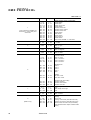
DMX PROTOCOL
Start code = 0
DMX channel
1
* If the command is disabled, set
channels 3, 4, and 5 (CMY) from
230 to 232.
2
3
4
5
6
7
8
9
(Mode 2 only)
26
Value
Percent
Function
0 - 19
20 - 49
50 - 112
113 - 127
128 - 147
148 - 167
168 - 187
188 - 207
208 - 217
218 - 227
228 - 237
238 - 247
248 - 255
0-7
8 - 19
20 - 44
44 - 50
50 - 58
58 - 65
66 - 73
74 - 81
82 - 85
85 - 89
89 - 93
93 - 97
97 - 100
Shutter, Strobe, Reset, Lamp On/Off
Shutter closed
Shutter open
Strobe, fast Æ slow
Shutter closed
Random strobe, fast
Random strobe, medium
Random strobe, slow
Shutter closed
Reset fixture*
Shutter closed
Lamp power on
Shutter closed
Lamp power off* Note: T ≥ 5 seconds
0 - 255
0 - 100
Intensity
0 Æ 100%
0-255
0 - 100
Cyan
White Æ Cyan
0-255
0 - 100
Magenta
White Æ Magenta
0-255
0 - 100
Yellow
White Æ Yellow
0 - 40
40 - 80
80 - 120
120 - 160
0 - 16
16 - 31
31 - 47
47 - 63
Color Wheel
Continuous Scroll
White Æ Color 1
Color 1 Æ Color 2
Color 2 Æ Color 3
Color 3 Æ Color 4
161 - 165
166 - 170
171 - 175
176 - 180
181 - 185
63 - 65
65 - 67
67 - 69
69 - 71
71 - 73
Stepped Scroll
Color 4
Color 3
Color 2
Color 1
White
186 - 214
215 - 243
73 - 84
84 - 95
Rotation
CW, fast Æ slow
CCW, slow Æ fast
244 - 247
248 - 251
252 - 255
96 - 97
97 - 98
99 - 100
Random Color (Uses CMY)
Random color fast
Random color medium
Random color slow
0-2
3 - 170
171 - 255
0-1
1 - 67
67 - 100
Beam Shaper
Open
Beam shaper left Æ right
Frost
0 - 255
0 - 100
Zoom
Wide Æ narrow
0-2
3 - 245
246 - 248
249 - 251
252 - 255
0-1
1 - 96
96 - 97
98 - 98
99 - 100
Exterior 600
Speed
Tracking
Fast Æ slow
Tracking, no shortcuts (override SCUT ON)
Tracking, shortcuts on (override SCUT OFF)
Dimmer, CMY, and zoom: fast (no blackout),
Color wheel and beam shaper: blackout while
moving
appendix b
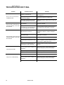
TR O U B L E S H O O T I N G
Problem
One or more of the fixtures is
completely dead.
Fixtures reset correctly but all
respond erratically or not at all to
the controller.
Fixtures reset correctly but some
respond erratically or not at all to
the controller.
Lamp does not strike.
Lamp cuts out intermittently.
27
Probable cause(s)
Remedy
Fixture not powered on.
Check that power is switched on and cables
are plugged in.
Primary fuse blown (located
besides the ballast).
Disconnect fixture and replace fuse.
Secondary fuse(s) blown (located
on PCB inside the fixture base).
Disconnect fixture. Check fuses on PCB and
replace.
The controller is disconnected from
the data link.
Connect controller.
XLR pin-out of the controller does
not match pin-out of the first fixture
on the link (signal is reversed).
Install a phase-reversing cable between the
controller and the first fixture on the link.
Bad data link connection
Inspect connections and cables. Correct poor
connections. Repair or replace damaged
cables.
Data link not terminated with 120Ω
termination plug.
Insert termination plug in output jack of the
last fixture on the link.
Incorrect addressing of the fixtures.
Check fixture address and protocol settings.
One of the fixtures is defective and
disturbs data transmission on the
link.
Bypass one fixture at a time until normal operation is regained. Have the defective fixture
serviced by a qualified technician.
XLR pin-out on fixtures does not
match (pins 2 and 3 reversed).
Install a phase-reversing cable between the
fixtures.
The ballast and transformer settings
do not match local AC voltage and
frequency.
Disconnect fixture. Check ballast and transformer settings and correct if necessary.
Lamp missing or blown
Install new lamp.
Lamp is too hot.
Allow lamp to cool for at least 8 minutes.
Fixture is too hot.
Allow fixture to cool.
The ballast and transformer settings
do not match local AC voltage and
frequency.
Disconnect fixture. Check ballast and transformer settings and correct if necessary.
Defective fan.
Refer to service technician.
Exterior 600
appendix c
SPECIFICATIONS
Physical
•
•
•
•
Length............................................................................................................................................ 636 mm (25.0 in)
Width ............................................................................................................................................. 375 mm (14.8 in)
Height ............................................................................................................................................ 421 mm (16.6 in)
Weight.............................................................................................................................................48 kg (105.6 lbs)
Compatible lamps
•
•
•
Osram HSR 575/2............................................................................................................... 1000 h, 6000K, 85 lm/w
Philips MSD 575 ................................................................................................................ 2000 h, 6000K, 75 lm/w
Philips MSR 575/2.............................................................................................................. 1000 h, 7200K, 85 lm/w
Pe rfor m an c e
•
Light output (6” Fresnel lens, MSR 575/2) ........................................................................................20,000 lumens
Thermal
•
Maximum ambient temperature (Ta) ................................................................................................. 40° C (104° F)
•
Maximum surface temperature .......................................................................................................... 80° C (176° F)
Co ntro l a nd p ro gr a m mi ng
•
•
•
•
•
•
Data pin-out ............................................................................................... pin 1 shield, pin 2 cold (-), pin 3 hot (+)
Receiver .................................................................................................................................. Opto-isolated RS-485
Setting and addressing .............................................................................................. remotely w/ MPBB1 Uploader
Protocols ................................................................................................. USITT DMX-512 (1990), Martin RS-485
DMX speed control ................................................................................................................ tracking and/or vector
DMX channels......................................................................................................................................................8-9
Connections
•
•
•
AC input...................................................................................................... 3 m (9.8 ft.) trailing cable w/o cord cap
Data input ....................................................................................4.5 m (14.7 ft.) trailing cable w/ 3-pin XLR male
Data output ...............................................................................4.5 m (14.7 ft.) trailing cable w/ 3-pin XLR female
Maximu m pow er and current
•
•
•
•
•
@ 200 V, 50 Hz..................................................................................................................................... 640 W, 4.0 A
@ 230 V, 50 Hz..................................................................................................................................... 670 W, 3.6 A
@ 245 V, 50 Hz..................................................................................................................................... 660 W, 3.4 A
@ 208 V, 60 Hz..................................................................................................................................... 640 W, 4.0 A
@ 227 V, 60 Hz..................................................................................................................................... 670 W, 3.6 A
Design standards
•
•
•
•
Canadian safety.......................................................................................................................... CSA C22.2 NO 166
EU EMC ......................................................................................................................................50 081-1, 50 082-1
EU safety .....................................................................................................................EN 60598-1, EN 60598-2-17
US safety........................................................................................................................................... ANSI/UL 1573
Construction
•
•
•
•
•
•
Housing....................................................................................................................................... extruded aluminum
Finish .................................................................................................................. Anodized, natural aluminum color
Front glass...................................................................................................................... 6 mm anti-reflection coated
Base ........................................................................................................................................... 6 mm stainless steel
Housing-to-base attachment ............................................................. 2 stainless steel M10 bolts, A2 DIN 933, 18.8
Protection factor ................................................................................................................................................IP 65
Installation
•
•
•
•
•
•
Mounting points.............................................................................. 4 curved 10 mm (3/8 in) slots on 85 mm radius
Orientation ........................................................................................................................................................... any
Swivel .............................................................................................................................................................+/- 25°
Tilt (pedestal mounted)...................................................................................................................................+/- 40°
Minimum distance to combustible materials........................................................................................... 1 m (39 in)
Minimum distance to illuminated surfaces.............................................................................................. 1 m (39 in)
Optional accessories
•
•
•
•
•
•
•
Narrow angle 8” Fresnel lens ............................................................................................................. P/N 91610014
Wide angle diffuser "lens" kit............................................................................................................. P/N 91610011
Narrow angle 8” Fresnel lens ............................................................................................................. P/N 41204010
MPBB1 Uploader ............................................................................................................................... P/N 90758410
MC-X Controller, 220 - 245 V / 50 Hz............................................................................................... P/N 90718200
MC-X Controller, 110 - 120 V / 60 Hz............................................................................................... P/N 90718300
MAC 600 Diffusion/color filter adaptor ............................................................................................. P/N 91611001
Selected spare parts
•
•
•
•
•
•
•
•
•
Exterior 600 seal kit (8 pcs.)............................................................................................................... P/N 91611017
Seal for alu. gable, Exterior 600 (4 pcs. included in seal kit)............................................................. P/N 20600020
Seal 1 for front lens, Exterior 600 (2 pcs. included in seal kit) .......................................................... P/N 20620060
Seal for lamp replacement, Exterior 600 (1 pc. included in seal kit) ................................................. P/N 20620050
Seal for bracket, Exterior 600 (1 pc. included in seal kit) .................................................................. P/N 20600010
Main fuse ...................................................................................................6.3 A / 250 V time delay, P/N 05020020
Fuse F601 .................................................................................................5.0 A / 250 V time delay, P/N 05020018
Fuse F602 ..................................................................................................4.0 A / 250 V time delay, P/N 05020016
Fuse F603 ..............................................................................................0.315 A / 250 V time delay, P/N 05020004
To r q u e s
•
•
•
ý
29
End plate Allen bolts ...................................................................................................................6 N.m (4.5 Ft-Lbs)
Lamp access plate........................................................................................................................6 N.m (4.5 Ft-Lbs)
Front glass ring ................................................................................................................. 3 - 4 N.m (2.2 - 3 Ft-Lbs)
Exterior 600