1
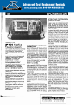
TEK
490
SERIES
494/494P
The 494P complies with IEEE Standard
488-1978, and with Tektronix Standard
_____Codes and Formats._________
Built-in Frequency Counter to 325 GHz
HELP Manual in ROM_____________
Nonvolatile Memory Storage_________
Keypad Data Entry_____________
Direct Plot Capability_____________
Alternate Language Options________
GPIB/Fully Programmable (494P)
Full Three Year Warranty__________
The TEK 494 and fully programmable 494P
offer portability, ease of use, and the widest
amplitude calibrated frequency range of
any spectrum analyzers available—10 kHz
to 21 GHz in coax, and 18 GHz to 325 GHz
using one or more of ten WM 490 Series
waveguide mixers.
Counter Center Frequency Accuracy,
Zero Long-Term Drift, Superior Range
and Resolution in a Compact, Portable
Package
A 4 GHz signal can be measured to within
41 Hz with 1 Hz readout resolution 30 minutes after turn on. And the 494's zero drift
will ensure long term measurement repeatability on that frequency.
10 kHz to 325 GHz
PORTABLE SPECTRUM ANALYZERS
You get 30 Hz resolution bandwidth to
60 GHz, 100 Hz resolution bandwidth to
220 GHz and 1 kHz bandwidth to 325 GHz
with excellent sensitivity and low phase
noise. Popular features common to other
490 Series spectrum analyzers are standard
on the 494, including digital storage, manual
to programmable convertibility, and environmentalization per MIL-T-28800C, Type III,
Class 3, Style C.
An exclusive pushbutton HELP mode
makes the 494 accessible to operators of
widely varying skills and experience. At the
touch of a button or twist of a knob the 494
tells you what to expect from nearly every
control—in plain English. Plus optional
French, German, or Spanish. Pull-out reference cards supply an additional level of detail. Having answers available at your fingertips minimizes training time and reduces
complexity.
Center Frequency, Span/Division, Amplitude Scaling and Reference Level Selected Either by /iP-Aided Three Knob
Operation or Direct Pushbutton Entry
In pushbutton mode, variables can be set to
nonstandard values, i.e., 7 dB/div vertical
mode or 9.2 kHz/div frequency span.
Nonvolatile memory retains up to ten setups and nine displays—for rapid measurements and easy data comparison. One
memory location stores on-screen settings
to quickly bring the analyzer back if power
is turned off.
The fully programmable 494P provides
easy-to-implement automated measurements. The 494P is straightforward to interface to our GPIB controllers . . . or yours. If
you want to free your controller but still get
graphics output, a convenient front panel
PLOT button will send display data to a
plotter.
Now increase your ATE capabilities with the
TekSPANS general RF applications software in IBM PC, HP or Tek controller versions. Automate your EMI verification testing
with the NEW TekSPANS EMI software. See
page 173.
In strong testimony of the incomparable reliability of the 494 and 494P, Tek offers the
first spectrum analyzer three year warranty.
Beyond the first three years of warranty coverage, Tek will extend your service coverage for two years, providing all your calibration and maintenance needs for the first five
years.
163
TEK
10 kHz to 325 GHz
490
SERIES
PORTABLE SPECTRUM ANALYZERS
The following characteristics and features apply
after a 30-minute warm-up period unless otherwise noted.
FREQUENCY RELATED
Center Frequency Range — 10 kHz to 21 GHz
standard; amplitude specified coverage to
325 GHz with optional Tektronix WM490 Series
Waveguide Mixers.
Center Frequency Accuracy — Bands 1 and
5-12 with span/div >200 kHz and bands 2-4 with
span/div > 100 kHz.
±[(20% of span/div or res BW, whichever is
greater) + (CF x Ref Freq Error) + (N x 15 kHz)].
Bands 1 and 5-12 with span/div <200 kHz and
Bands 2-4 with span/div <100 kHz.
±[(20% of span/div or res BW, whichever is
greater) + (CF x Ref Freq Error) + (2N +
25 Hz)].
Typical Low Frequency Response
and Average Noise Level
Center Frequency Readout Resolution — At
least 10% of span/div.
1MHz
Signal Counter Accuracy — ± [(Counter Frequency x Ref Freq Error) + (10 + 2N) Hz +
SENSITIVITY AND FREQUENCY RESPONSE
1 LSD)].
Counter Sensitivity — Center Screen S/N
Counter Frequency Readout Resolution —
10MHz
Ave Noise Level
for 1 kHz Res BW
Minimum Frequency
Counter Sensitivity
Minimum Res BW
Freq Response
Referenced
to 100 MHz
With 10 dB Attn
Freq Response
About the MidPoint Between
Two Extremes
LO
Frequency Range
Harmonic
Number
1 Hz through 1 GHz.
10 kHz- 1.8 GHz
1
-110dBm
-101 dBm
±3.0dB
±2.0dB
Reference Frequency Error (Aging Rate) —
50kHz-1.8GHz
1
- 1 10 dBm
-101 dBm
±2.5dB
±1.5dB
1.7GHz-5.5GHz
3.0GHz-7.1GHz
1
1
-110dBm
-110 dBm
-101 dBm
±3.5dB
±3.5dB
±2.5dB
±2.5dB
5.4GHz-18.0GHz
5.4GHz-12GHz
12GHz-18GHz
3
±4.5dB
±3.5dB
-95 dBm
-90 dBm
-86 dBm
-81 dBm
15.0 GHz-21.0 GHz
3
-85 dBm
-76 dBm
±6.5dB
±5.0dB
1 x 10⁻⁹/day, 1 x 10⁻⁷/year.
Frequency Span/Division Range — 50 Hz/div
to 500 MHz/div in coaxial bands (10 kHz through
21 GHz) and 50 Hz/div to 10 GHz/div in waveguide bands (18 GHz through 325 GHz), plus zero
span and maximum span. Any span to two significant digits (within 50 Hz and up to 10 GHz) can
also be selected with the Data Entry Keyboard.
Frequency Span/Division Accuracy — Within
5% of the selected span/div over the center eight
divisions of the ten division CRT display.
Resolution Bandwidth (6 dB) — 30 Hz then
100 Hz to 1 MHz in decade steps plus auto. Accuracy: Within 20%.
Resolution Shape Factor (60dB/6dB) —
7.5:1 or less, 100 Hz through 1 MHz and 15:1 or
less for 30 Hz.
Residual FM (After One Hour Warm-Up) —
Bands 1 and 5-12 with span/div >200 kHz, and
bands 2-4 with span/div >100 kHz: <(7 kHz) N
total excursion in 20 ms.
Bands 1 and 5-12 with span/div <200 kHz, and
bands 2-4 with span/div <100 kHz: <(10 -I- 2N)
Hz total excursion in 20 ms.
Long Term Drift (at Constant Temperature
and Fixed Center Frequency and After OneHour Warm-Up) — Bands 1 and 5-12 with span/
WITH TEKTRONIX OPTIONAL HIGH PERFORMANCE WM 490 SERIES WAVEGUIDE MIXERS
Harmonic
Number
Ave Noise Level
for 1 kHz Res BW
Minimum Frequency
Counter Sensitivity
Minimum Res BW
Freq Response
Referenced
to 100 MHz
With 10 dB Attn
Freq Response
About the MidPoint Between
Two Extremes
6
-100 dBm
-91 dBm
±6.0dB
±2.0dB
26.5 GHz-40 GHz
WM490A
10
-95 dBm
— 86 dBm
±6.0dB
±2.0dB
33 GHz-50 GHz
WM490Q
10
-95 dBm
-86 dBm
±6.0dB
±2.0dB
40 GHz-60 GHz
WM490U
10
-95 dBm
-86 dBm
±6.0dB
±2.5dB
50 GHz-75 GHz'
WM490V
@ 50 GHz
@ 75 GHz
15
±6.0dB
±3.0dB
—95 dBm
-90 dBm
-86 dBm
-81 dBm
60 GHz-90 GHz'
WM 490E
@ 60 GHz
@ 90 GHz
15
±6.0dB
±3.0dB
-95 dBm
-85 dBm
-89 dBm
-79 dBm
75GHZ-110GHZ*
WM490W
@ 75 GHz
23
±6.0dB
±3.0dB
-90 dBm
-80 dBm
-84 dBm
-74 dBm
±6.0dB
±3.0dB
-85 dBm
-75 dBm
-79 dBm
-69 dBm
±6.0dB
±3.0dB
-80 dBm
-70 dBm
-74 dBm
±6.0dB
±3.0dB
-75 dBm
-65 dBm
-69 dBm
±6.0dB
±3.0dB
-65 dBm
-50 dBm
-50 dBm
LO
Frequency Range
18.0 GHz-26.5 GHz
WM490K
@ 110 GHz
90 GHz- 140 GHzWM490F
@ 90 GHz
© 140 GHz
23
110GHZ-170GHZ'
WM 490D
@ 1 10 GHz
37
> 100 kHz: <(5 kHz) N per minute of sweep time.
Bands 1 and 5-12 with span/div <200kHz, and
Bands 2-4 with span/div <100 kHz: «!50 Hz per
minute of sweep time.
140 GHz-220 GHzWM 490G
© 140 GHz
@ 220 GHz
37
220 GHz-325 GHz"
119-1728-00 @ 220 GHz
© 325 GHz
56
div >200kHz, and bands 2-4 with span/div
Noise Sidebands — At least -75dBc at
30 times the resolution bandwidth offset from the
center frequency (—70 dBc for 100 Hz resolution
bandwidth or less).
164
-101 dBm
@ 170 GHz
-64 dBm
-59 dBm
-35 dBm
• Typical values and with frequency response indicated over any 5 GHz range.
TEK
10 kHz to 325 GHz
PORTABLE SPECTRUM ANALYZERS
490
SERIES
AMPLITUDE RELATED
External Reference Frequency — 1 MHz,
Reference Level Range (Full Screen, Top of
2 MHz, 5 MHz or 10 MHz ±5ppm (minimum).
Waveshape: Sinewave, ECL, TTL duty cycle
40%-60%. Input Impedance: SOflac, 500fide.
Power: -15 dBm to +15 dBm.
Graticule) — - 1 1 7 d B m to +40 dBm
(+40dBm includes maximum safe input of
+30 dBm and 10 dB gain of IF gain reduction) for
10 dB/div and 2 dB/div log modes. 1 W maximum
safe input in the linear mode.
Reference Level Accuracy — Accuracy is a
function of the characteristics listed below.
Calibrator: (Cal out) See output signal characteristics on page 158.
Input Attenuator Accuracy: DC to 1.8 GHz:
0.5 dB/10 dB, 1 dB max accumulative. 1.8 GHz to
18 GHz: 1.5 dB/10 dB, 3dB max accumulative.
18 GHz to 21 GHz: 3.0 dB/10 dB, 6 dB max
accumulative.
Frequency Response: See Frequency Response
Table on page 164.
Display Amplitude Accuracy, Resolution
Bandwidth Gain Variation and IF Gain Variation — Same as 495 (see page 158).
SPURIOUS RESPONSES
Residual (No Input Signal Referenced to Mixer
Input) — —100 dBm or less. Fundamental mixing
Bands 1-3.
Harmonic Distortion (CW Signal Minimum Distortion Mode) — Typically -60 dBc for -40 dBm
signal in the minimum distortion mode to 21 GHz. At
least -100 dBc for preselected bands 1.7 GHz to
21 GHz.
Third-Order Intermodulation Distortion (Minimum Distortion Mode) — At least 70 dB down
from two full screen signals within any frequency
span. At least 100 dB down for two signals spaced
more than 100MHz apart from 1.7 GHz to 21 GHz
for preselected bands.
LO Emissions (No RF Attenuation) —
—70 dBm maximum to 21 GHz.
INPUT SIGNAL
RF Input — Type N female connector.
Maximum Safe Input Level (RF Attenuation at
Zero dB) — +30 dBm (1 W) continuous, 75 W
peak for 1 /ts or less pulse width and 0.001 maximum duty factor (attenuation limit). DC must never
be applied to RF input.
OUTPUT SIGNAL
For details see page 158.
IEEE Standard 488-1978 Interface Function
Subsets Implemented — (494P) Source Handshake: SH1. Acceptor Handshake: AH1. Talker: T5.
Listener: L3. Service Request: SR1. Remote/Local:
RL1. Parallel Poll: PP1. Device Clear: DC1. Device
Trigger: DT1. Controller: CO.
GENERAL CHARACTERISTICS
ENVIRONMENTAL
Per MIL-T-28800C Type III, Class 3, Style C. For
Details, see page 159.
ORDERING INFORMATION
(378-072601); two 4 A fast bbw fuse (159O017OO); 115V
power cord (161-0118-00); cord clamp (343017000); CRT
visor (016O653OO); amber CRT light filter (378-011501);
gray CRT light filter (378O115O2); blue CRT light filter
(378O115OO); operator manual (070-441800); operator
handbook (070-4419-00); service manual, volume 1
(070-441600); service manual, volume 2 (070-441700).
494P Programmable Spectrum
$46,995
Includes: In addition to the above a 2 m double shielded GPIB cable (012-0630-03); programmer manual
(070-441500).
Input Impedance — 501).
Typical
Specified Maximum
DC to 2.5 GHz
1.2:1
1.3:1
2.5 GHz to 6.0 GHz
1.5:1
1.7:1
6.0 GHz to 18 GHz
1.9:1
2.3:1
input).
18 GHz to 21 GHz
2.7:1
3.5:1
50 kHz to 2 5 GHz
1.9:1
2.5 GHz to 60 GHz
1.9:1
6.0 GHz to 180 GHz
2.3:1
18.0 GHz to 21.0 GHz
3.0:1
''At Type N female connector to internal mixer.
Input Level (Optimum Mixer Level for Minimum
Distortion Linear Operation) — -30 dBm (minimum distortion control setting); 1 dB gain compression -23 dBm.
Optimum Mixer Level for Minimum Noise Display Dynamic Range Enhanced Operation —
—20 dBm (minimum noise control setting); 1 dB
gain compression —18 dBm.
-$1,750
Option 12 — Help Mode Text. CRT prompts
selectable between German and English.
Pull-out reference cards in German.
(494)
(494P)
+$200
+$500
+$200
+$500
+$200
+$500
Option 20 — General Purpose 12.4 GHz to
4nnH7 Waveguide Mixer Set. (12.4 GHz to
18 GHz, 18 GHz to 26.5 GHz, and 26.5 GHz to
40 GHz) and hardware.
Option 21 — High Performance 18 GHz to
+$840
Option 32 — Benchmount. Adds side and
top panels, earn/ing handles and feet for a
stackable bench top configuration.
Option 41 — Digital Radio. Provides wider
bandwidth preselector, 30 Hz video filter with
100kHz resolution bandwidth and 5 MHz
span/div optimized for 6 GHz and 11 GHz
D/R.
Option 42 — 110MHz IF Output. Provides
5 MHz bandwidth at 6 dB points.
+$940
+$450
+$1,500
Option 45*1 — (494P only) MATE/CIIL.
494 to 494P — Conversions are made by
your nearest Tektronix Service Center.
Order 040-114001
$5,300
INTERNATIONAL POWER PLUG OPTIONS
Option A1 — Universal Euro 220 V, 50 Hz.
Option A2 — UK 240 V, 50 Hz.
Option A3 — Australian 240 V, 50 Hz.
Option A4 — North American 240 V, 60 Hz.
Option AS — Switzerland 220 V, 50 Hz.
WARRANTY-PLUS SERVICE PLANS
SEE PAGE 497
M1 — (494) 2 Calibrations.
+$695
M1 — (494P) 2 Calibrations.
M2 — (494) 2 Years Service.
M2 — (494P) 2 Years Service.
+$715
+$1,330
+$1,350
M3 — (494) 2 Years Service & 4 Calibrations. +$2,725
M3 — (494P) 2 Years Service & 4 Calibrations. +$2,785
M4 _ (494) 5 Calibrations.
+$1,590
M4 — (494P) 5 Calibrations.
+$1,630
MS — (494) 9 Calibrations + 2 Years Service. +$4,145
MS — (494P) 9 Calibrations + 2 Years Service. +$4,240
OPTIONAL ACCESSORIES
$6,620
$1,800
Order 011O112OO
DC Block N to N — Order 015-0509-00
P6201 — FET Probe to 900 MHz.
TV Trigger Synchronizer —
Order 015O261O1
Hard Case (Transit) — Order 016-0658-00
Soft Case — Order 016O659OO
Rear Panel Protective Cover —
Order 337-327400
Lab Cart — K213. (See page 462.)
Camera — C-5C. (See page 445.)
selectable between Spanish and English.
Pull-out reference cards in Spanish.
(494)
(494P)
page 160.
1405 TV Sideband Adaptor — 525/60
Markers. See page 179.
Option 13 — Help Mode Text. CRT prompts
selectable between French and English. Pullout reference cards in French.
(494)
(494P)
Option 14 — Help Mode Text. CRT prompts
60 GHz) and hardware.
+$4,250
Option 30 — Rackmount. 19 inch rack width
with front panel input/outputs. See page 160. +$790
Option 31 — Rackmount. 19 inch rack width
with rear panel input/output capability. See
TR 503 Tracking Generator — See
page 178.
Microwave Comb Generator — TM500
Series compatible. Order 067O885OO
75 0 to 50 Q Minimum Loss Pad —
OPTIONS (494/494P)
Option 08 — Delete External Mixer Capability. Deletes internal switching, front panel connector and external diplexer to connect and
use external waveguide mixers. Limits frequency range to 10 kHz to 21 GHz (coaxial
Maximum VSWR* 1 With sMOdB Attenuation
Frequency Range
$42,175
Includes: Diplexer assembly (015O385OO); 6ft N to N
connector 50 SJ coax cable (012-0114-00); N male to BNC
female adaptor (103-0045-00); 18 in BNC to BNC connector, 50 Q coax cable (012-0076-00); CRT mesh filter
Analyzer
26.5 GHz, 26.5 GHz to 40 GHz, and 40 GHz to
CONVERSION KIT
For details see page 159.
494 Spectrum Analyzer
Option 22 — High Performance 18 GHz to
60 GHz Waveguide Mixer Set. (18 GHz to
+$900
Note: 490 Series spectrum analyzers are compatible with all
Tektronix C-50 Series cameras.
PERIPHERAL PRODUCTS FOR
494P SPECTRUM ANALYZER
4041 — System Controller (see page 355)
$4,950
4207 — Color Graphics Terminal (see
page 53).
$3,995
40 GHz Waveguide Mixer Set. (18 GHz to
26.5 GHz and 26.5 GHz to 40 GHz) and hardware.
+$2,525
165