1
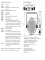
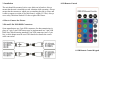
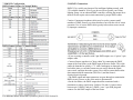
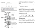
Notes
10. DMX General Information
The DMX512 digital communication protocol was introduced to control
stage lighting and special effects.
The DMX standard features 512 available channels, and they are
assignable in any sequence that conforms to the user's needs. Each DMXcapable fixture requires one or more sequential channels. A starting
address, which indicates the first control channel reserved for that
particular fixture, must be assigned to the fixture before the controller can
recognize it. DMX controllable fixtures may vary in the number of
channels they require, depending on the fixtures features and/or
functionality.
Channels should never be permitted to overlap; otherwise, for example, a
fader that controls blue output on one fixture may cause strobing or
dimming on an adjacent, incorrectly assigned fixture. Multiple fixtures of
the same type that use an identical starting address will function in unison.
Fixtures assigned properly spaced starting addresses will operate
individually, but a DMX controller with sufficient channels can be
configured to run these same fixtures either combined or independently.
The sequence in which DMX fixtures are connected has no effect on how
a controller communicates with each individual lighting fixture. Although
3-pin XLR mic cables may be used to connect DMX fixtures over short
runs, longer distances will introduce data errors due to the mic cable's
incorrect impedance. For best results, Talent Sound & Lighting
recommends the use of correct 120 ohm, low-capacitance, twisted pair
cable designed for the DMX512 protocol. It is also suggested that a
termination resistor plug be used on the output connector of the last fixture
in an array of DMX instruments. This resistance ensures proper data
transmission.
TABLE OF CONTENTS
1. Safety Instructions
2. Technical Specifications
3. Installation
4. How to Connect the Fixture
5. DMX512 Connections
6. How to Set the Unit
7. DMX Configuration
8. IR Remote Control
9. Troubleshooting
10. DMX General Information
1. Safety Instructions
9. Troubleshooting
• Please keep this User Manual for future consultation. If you sell the
fixture, be sure to include this instruction booklet to ensure proper
maintenance and use.
• Unpack and check carefully for transportation damage before using the
fixture.
• Before operating, ensure that the power supply voltage and frequency
match the power of your electrical system.
• It's important to connect the yellow/green conductor to ground to avoid
electric shock.
• Disconnect main power before servicing and maintenance.
• Use a safety cable when permanently mounting this fixture. Always
handle the fixture with care.
• Maximum ambient temperature is 104° F.
• In the event of a serious operating problem, stop using the fixture
immediately. Please contact the dealer from whom you purchased the
fixture, the nearest authorized technical repair facility, or Talent Sound &
Lighting directly.
• Do not connect the device to any dimmer pack.
• Do not touch exposed wires during use, as there might be a hazard of
electrical shock.
• To prevent or reduce the risk of electrical shock or fire, do not expose
the fixture to rain or moisture.
• The fixture must be replaced if there is visible damage to the housing.
• Do not look directly at the LED light beam while the fixture is on.
Here are some troubleshooting suggestions:
Warning: Please read the instructions carefully. They include important
information about installation, operation, and maintenance. Do not
connect more than 32 units in series (daisy-chaining) on a single power
circuit.
D. The fixture doesn't respond to sound.
1.) Make sure the fixture is not set to receive a DMX signal.
2.) Check the fixture's internal microphone by tapping the microphone.
Caution: There are no user serviceable parts inside the fixture. Do not
open the housing or attempt any repairs yourself. In the unlikely situation
your unit may require service, please contact your dealer or Talent Sound
& Lighting.
A. The fixture does not work, there is no light output.
1.) Check the connection of power and main fuse.
2.) Measure the voltage output on your power receptacle to ensure proper
voltage.
B. Fixture does not respond to DMX control.
1.) DMX LED should be on. If not, check DMX connectors and cables for
proper connection.
2.) If DMX LED is on but not responding to a channel, check the DMX
address settings and DMX polarity.
3.) If you have intermittent DMX signal problems, check the pins on the
cable connectors and on the fixture.
4.) Try to use a different DMX controller.
5.) Interference may occur if DMX cables are run alongside high voltage
cables.
C. Fixture responds erratically to DMX control.
1.) You may have a break in the DMX cabling. Check the LED for the
response of the master/ slave mode signal.
2.) Wrong DMX address in the fixture. Set the fixture to the proper
address.
3.) Use of microphone cables for DMX connections can cause errors
8.2 IR Remote Control Functions
2. Technical Specifications
(1) Auto
(2) Sound
(3) DMX
Auto show
Sound active
DMX512 control, switch mode between address
and channel.
(4) Black Out Acts as a shutoff button when activated.
(5) Red
Red LEDs on
(6) Green
Green LEDs on
(7) Blue
Blue LEDs on
(8) White
Red, Green, and Blue LEDs are turned on
(9)
Increase parameters
(10)
Reduce parameters
(11) 0~9
In DMX mode, the 0 through 9 buttons set DMX
addresses on the fixture. When DMX is first selected, the
0~9 buttons change the address. Pressing the DMX button
again allows you to change the channel mode. In Color
mode, the 0~9 buttons can be used to input values directly
to select custom colors.
(12) Jump
Jump color change mode
(13) Fade
Gradual change mode
(14) Color
Color mode, static colors ranging from 0 (off) to 255. If
the program is not in Color mode, and you want to select
a custom color, you must first press the Color button. Use
numbered 0~9 buttons to manually input a value, and/or
buttons (+) and (-) to adjust selection. As a general
guideline, C042 = green; C126 = red; and C210 = blue.
Values above, below, and between these values will be
gradual mixtures of red, green, and blue, accordingly.
(15) Flash
Only in Auto, Fade, Jump, and COLOR modes.
Press once for strobe mode, press again to return to the
previous program.
Note: Please make sure there is nothing between the remote controller and
the fixture. Maximum distance for the remote to work is 10 meters.
• DMX channels: 3/5/7 selectable via digital display
• 181 Ultra Bright 10 mm LEDs (Red: 49, Green: 72, Blue: 60)
• 125 Static Colors/Dimmer/Strobe/Fade/Jump
• Auto, sound active, DMX, and master/slave modes
• Internal programs with sound activation
• 3-pin XLR in/out sockets for DMX control
• RGB color mixing
• Beam angle: ±20°
• Power consumption: 20 watts
Power input: AC 90V-250V, 50-60 Hz
• Dimension: 10.83" diameter x 4.13" deep
• Weight: 3.52 lbs.
3. Installation
8. IR Remote Control
The unit should be mounted via its screw holes on its bracket. Always
ensure that the unit is installed to avoid vibration while operating. Always
ensure that the structure to which you are attaching the unit is secure and
is able to support a weight of 10x this fixture's weight (35.2 lbs.) Always
use a safety cable that can hold 12x the weight of the fixture.
4. How to Connect the Fixture
3-Pin and 5-Pin XLR DMX Connectors:
Some manufactures use 5-pin XLR connectors for data transmission in
place of 3-pin. 5-pin XLR fixtures may be implemented in a 3-pin XLR
DMX line. When inserting standard 5-pin XLR connectors into a 3-pin
line, a cable adapter must be used. The chart below details the correct
cable conversion.
8.1 IR Remote Control Keypad
7. DMX512 Configuration
DMX Channel Values (3-Channel Mode)
DMX Channel Values (5-Channel Mode)
5. DMX512 Connections
DMX512 is a widely used protocol for intelligent lighting control, with
512 available channels. Even if you do not wish to operate your Talent
lighting fixture via an outboard DMX controller, utilizing the master/slave
mode will still require unit-to-unit connection by proper DMX cables.
Caution: Common microphone cables may be used to connect small
numbers of DMX fixtures over short distances, but offer the risk of erratic
operation. Use of correct DMX cables greatly reduces data errors caused
by improper connection.
DMX Channel Values (7 Channel Mode)
• If you are using a controller with 5-pin DMX output, use a 5-pin to 3-pin
adapter cable.
• Connect fixtures together in a "daisy chain" by connecting the DMX
output of the first fixture to the DMX input of the next fixture. This cable
cannot be branched or split by a "Y" cable. Inadequate or damaged cables,
bad solder joints, or corroded connectors can easily distort the signal,
cause errors, and shut down the system. Never allow contact between the
data common/shield connection (XLR Pin 1) and the fixture's
chassis/electrical ground.
• The DMX output and input connectors are pass-through to maintain the
DMX circuit if power to one of the units is disconnected.
• On the last fixture, the DMX output should be terminated with a
terminator to reduce signal errors. Solder a 120 ohm 1/4 watt resistor
between pin 2 (DMX-) and pin 3 (DMX+) on a 3-pin XLR plug and
connect it to the DMX output of the last fixture.
For additional details about DMX operation, please review Section 10.
6. How to Set the Unit
6.1 Control Panel
Your Talent Sound & Lighting fixture may be operated as a stand-alone
device that runs on pre-programmed routines or sound activation, in
master/slave mode with other devices, or via an external DMX512
controller. In DMX mode it is configurable to be controlled by 3, 5, or 7
channels.
Besides stand-alone operation, there are two main ways to control the
fixture:
A. Universal DMX control mode
B. Master/Slave operation
6.2 Main Function
A. Universal DMX controller
This fixture's DMX address can be set remotely by a universal DMX
controller. First, you need to program two scenes into a chase, and then
link the fixtures to the universal DMX controller. When you run the chase,
the fixtures in the chain will set the series DMX address automatically.
Each lighting fixture needs to have an address set when in DMX mode, to
receive the data sent by the controller. The address number is between 0511 (usually 0 & 1 are equal to 1). Please refer to the following diagram to
set the address for the first four units.
The numbers 1, 5, 9, and 13 indicate the starting address of each of the
fixtures.
B. Master/Slave operation
The fixture allows you to link as many as 16 fixtures together and operate
without a controller. In Master/Slave mode, the first fixture will control
the others to give an automatic, sound activated, synchronized light show.
This function is good for when you want an instant performance. The first,
or master, fixture's DMX input will have nothing connected to it. Its
output connects to the slave fixtures, which will be set in slave mode
automatically.