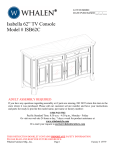
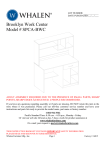
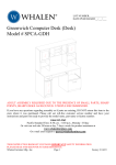
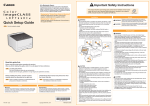
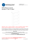
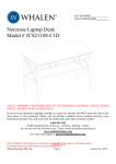
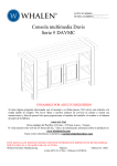
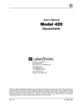
1
LOT NUMBER:
DATE PURCHASED:
/
/
Flat Panel TV Stand
Model # PROEC41-NV
ADULT ASSEMBLY REQUIRED
If you have any questions regarding assembly or if parts are missing, DO NOT return this item to
the store where it was purchased. Please call our customer service number and have your
instructions and parts list ready to provide the model name, part name or factory number:
1-866-942-5362
Pacific Standard Time: 8:30 a.m. - 4:30 p.m., Monday - Friday
Or visit our web site 24 hours a day, 7 days a week for product assistance at
www.whalenfurniture.com
Or e-mail your request to [email protected]
THIS INSTRUCTION BOOKLET CONTAINS IMPORTANT SAFETY INFORMATION.
PLEASE READ AND KEEP FOR FUTURE REFERENCE.
Whalen Furniture Mfg., Inc.
Page 1
Factory No. 33- 10944
Model # PROEC41-NV
MAXIMUM RECOMMENDED WEIGHT LOADS
MANUFACTURER: Whalen Furniture Mfg., Inc.
CATALOG: Flat Panel TV Stand (PROEC41-NV)
DATE OF MANUFACTURE: July 2013
MADE IN CHINA
FITS UP TO MOST 47” FLAT PANEL TVs
MAXIMUM LOAD 135 lb. (61.2 kg)
MAXIMUM LOAD 50 lb. (22.6 kg)
THIS UNIT IS NOT INTENDED FOR USE WITH CRT TVS. USE ONLY WITH
FLAT PANEL TVS AND AUDIO/VIDEO EQUIPMENT MEETING RECOMMENDED SIZE AND
WEIGHT LIMITS. NEVER USE WITH LARGER/HEAVIER THAN RECOMMENDED FLAT
PANEL TVS OR EQUIPMENT. TO AVOID INSTABILITY, PLACE FLAT PANEL TV IN THE
CENTER OF THE UNIT; CRT TVS, IMPROPERLY POSITIONED FLAT PANEL TVS, OR FLAT
PANEL TVS OR OTHER EQUIPMENT THAT EXCEED RECOMMENDED SIZE AND WEIGHT
LIMITS COULD FALL OFF OR BREAK THE UNIT, CAUSING POSSIBLE SERIOUS INJURY.
GENERAL INFORMATION, TIPS and TRICKS
1.
2.
3.
4.
5.
6.
7.
Please read the Assembly Instructions prior to assembling this product.
Remove all hardware from the box and sort by size.
Check to see that all hardware and parts are present BEFORE assembling.
Ask a friend to assist you with the assembly of this furniture.
To avoid damage, assemble the product on a sturdy, level and protective surface.
Please wait until all steps are completed before fully tightening Bolts.
Make sure all Bolts are tightly fastened before the unit is used.
This product is sold with one set of Tipping Restraint Hardware Kit. You must install the Tipping
Restraint Hardware between the wall and the TV stand to prevent any accidents or damages.
When properly installed, this restraint can provide protection against the unexpected tipping of
the unit due to small tremors, bumps or climbing. The restraint is only a deterrent and is not a
substitute for proper adult supervision. Use of tip-over restraints may only reduce, but not
eliminate, the risk of tip-over.
Please call for replacement parts or assistance: 1-866-942-5362
Whalen Furniture Mfg., Inc.
Page 2
Factory No. 33- 10944
Model # PROEC41-NV
Parts and Hardware List
Please read completely through the instructions and verify that all listed parts and hardware
are present before beginning assembly.
A- Left Side Frame (1)
D - Back Top Frame (1)
G- Top Stringer (1)
J- Bottom Brace (1)
M- Right Front Post (1)
P- Bottom Glass Shelf (1)
B- Right Side Frame (1)
C- Back Panel (1)
E- Back Bottom Stretcher (1)
F- Top Crossbar (1)
H- Middle Crossbar (1)
I- Middle Stringer (1)
K- Bottom Stringer (1)
N- Top Glass (1)
Q- Swiveling Bracket (1)
S- Monitor Bracket (2)
Please call for replacement parts or assistance: 1-866-942-5362
Whalen Furniture Mfg. Inc.
Page 3
L- Left Front Post (1)
O- Middle Glass Shelf (1)
R- Mounting Frame (1)
T- Cable Wheel (2)
Factory No. 33- 10944
Model # PROEC41-NV
Parts and Hardware List
(1) Suction Cup
(15+1 extra)
(2) 5/8” Bolt
(10+1 extra)
(5) 1-5/8” Bolt
(12+1 extra)
(6) 2-1/4” Bolt
(6+1 extra)
(9) Flat Washer (44+2 extra)
Touch-up Pen
(1)
(3) 3/4” Bolt
(8+1 extra)
(7) Hex Nut
(8+1 extra)
(10) #4 x 10 mm Screw (4+1 extra)
Open Wrench
(1)
M4 Allen Wrench
(2)
(4) 1-1/4” Bolt
(4+1 extra)
(8) Lock Washer
(40+2 extra)
(11) Floor Leveler (2)
Tipping Restraint Hardware Kit (1)
(Inside Plastic Bag)
TV Mounting Kit
M4 x 12 Bolt (4)
M6 x 12 Bolt (4)
M4 Lock Washer (4)
Large Spacer (4)
M4 x 30 Bolt (4)
M6 x 35 Bolt (4)
M5 Lock Washer (4)
Small Spacer (4)
M5 x 12 Bolt (4)
M5 x 30 Bolt (4)
M8 x 16 Bolt (4)
M8 x 40 Bolt (4)
M6 Lock Washer (4)
M4/M5 Flat Washer (8)
M8 Lock Washer (4)
M6/M8 Flat Washer (4)
Tools required: Allen Wrench, Open Wrench (provided) and Phillips screwdriver (not provided).
Please call for replacement parts or assistance: 1-866-942-5362
Whalen Furniture Mfg., Inc.
Page 4
Factory No. 33- 10944
Model # PROEC41-NV
Assembly Instructions
D
5
A/B
A/B
E
5
1-5/8” Bolt
(8 used in this step)
⑤
Lock Washer
(8 used in this step)
⑧
Flat Washer
(8 used in this step)
⑨
NOTE: Please do not fully tighten all bolts until you finish assembling all parts. Once assembled,
go back and fully tighten all bolts. This will make the assembly easier.
1. Attach the Back Top Frame (D) and the Back Bottom Stretcher (E) between Left and Right
Side Frames (A and B). Make sure that the metal brackets on Back Bottom Stretcher (E) face
up and point forward. Tighten the bolts with the enclosed M4 Allen Wrench.
Please call for replacement parts or assistance: 1-866-942-5362
Whalen Furniture Mfg. Inc.
Page 5
Factory No. 33- 10944
Model # PROEC41-NV
Assembly Instructions
#4 x 10 mm Screw
(4 used in this step)
⑩
2. Pick up the Back Panel (C) and fit it between the front of Left and Right Side Frames (A and B),
as shown above. Insert and screw four 10 mm Screws (10) through the corner brackets to
secure the Back Panel in place. Make sure that the oval holes on the Back Panel are down.
Tighten the screws with a Phillips screwdriver.
Please call for replacement parts or assistance: 1-866-942-5362
Whalen Furniture Mfg., Inc.
Page 6
Factory No. 33- 10944
Model # PROEC41-NV
Assembly Instructions
Flat Washer
(2 used in this step)
⑨
Lock Washer
(2 used in this step)
2-1/4” Bolt
(2 used in this step)
⑥
⑧
Floor Leveler
(2 used in this step)
⑪
3. Lay down the unit on a level and protective surface, as shown.
4. Screw the Floor Levelers (11) into the front sockets underneath the bottom rail of Left
and Right Side Frames (A and B). Set the Levelers to the correct height.
5. Attach the Bottom Brace (J) to the bottom rail of Left and Right Side Frames (A and B).
Please call for replacement parts or assistance: 1-866-942-5362
Whalen Furniture Mfg. Inc.
Page 7
Factory No. 33- 10944
Model # PROEC41-NV
Assembly Instructions
1-5/8” Bolt
(4 used in this step)
⑤
Lock Washer
(4 used in this step)
⑧
Flat Washer
(4 used in this step)
⑨
6. Attach the Middle Crossbar (H) to the middle rail of Left and Right Side Frames (A and B).
Tighten the bolts with enclosed M4 Allen Wrench.
7. Repeat the last step to attach the Top Crossbar (F) to the top rail of Left and Right Side
Frames (A and B).
Please call for replacement parts or assistance: 1-866-942-5362
Whalen Furniture Mfg., Inc.
Page 8
Factory No. 33- 10944
Model # PROEC41-NV
Assembly Instructions
8
2
8
2
5/8” Bolt
(6 used in this step)
②
Lock Washer
(6 used in this step)
⑧
Flat Washer
(6 used in this step)
⑨
8. Align and attach the Stringers (G, I and K) to the end brackets on the front rails of the Side
Frames (A and B) respectively, as shown above. Make sure that the top surface of stringers
and back crossbars are flush with each other.
Please call for replacement parts or assistance: 1-866-942-5362
Whalen Furniture Mfg. Inc.
Page 9
Factory No. 33- 10944
Model # PROEC41-NV
Assembly Instructions
3/4” Bolt
(4 used in this step)
③
98
4
98
3
1-1/4” Bolt
(4 used in this step)
④
Lock Washer
(8 used in this step)
⑧
Flat Washer
(8 used in this step)
⑨
9. Stand the last assembly upright.
10. Align and attach Left and Right Front Posts (L and M) to the Middle Stringer (I) and the Bottom
Stringer (K), as shown above.
Please call for replacement parts or assistance: 1-866-942-5362
Whalen Furniture Mfg., Inc.
Page 10
Factory No. 33- 10944
Model # PROEC41-NV
Assembly Instructions
8
UP
Q
D
2-1/4” Bolt
(4 used in this step)
⑥
Hex Nut
(4 used in this step)
⑦
Lock Washer
(8 used in this step)
⑧
Flat Washer
(8 used in this step)
⑨
11. Attach the Swiveling Bracket (Q) to the top of the Back Top Frame (D) with the pivoting bolt
head up, as shown. Securely tighten with the provided Open Wrench and M4 Allen Wrench.
NOTE: The Back Top Frame can provide three height options for your TV set. Refer to your
TV size and adjust the Swiveling Bracket at your desired height for optimum viewing.
Please call for replacement parts or assistance: 1-866-942-5362
Whalen Furniture Mfg. Inc.
Page 11
Factory No. 33- 10944
Model # PROEC41-NV
Assembly Instructions
UP
3/4” Bolt
(4 used in this step)
③
Hex Nut
(4 used in this step)
⑦
Lock Washer
(4 used in this step)
Flat Washer
(8 used in this step)
⑧
⑨
12. Attach the Mounting Frame (R) to the Swiveling Bracket (Q) using four 3/4” Bolts (3) with
Washers (8 and 9) and then secure with the Hex Nuts (7). As shown above.
13. Go back and tighten all bolts with the enclosed Allen Wrench and Open Wrench.
Please call for replacement parts or assistance: 1-866-942-5362
Whalen Furniture Mfg., Inc.
Page 12
Factory No. 33- 10944
Model # PROEC41-NV
Mounting Monitor Bracket to a television with a flat back
TV
NOTE: For televisions with a curved or recessed back, proceed directly to the next page.
14. Determine the correct diameter of the bolt your TV requires by hand threading them into the
threaded inserts on the back of the TV. If you encounter any resistance, stop immediately. If
you are unable to find the correct bolt consult a local hardware store.
15. Follow the appropriate diagram above to attach the Monitor Brackets (S) to the back of your
TV with the selected fasteners. Make sure the Monitor Brackets are centered and level with
each other. Secure the bolts with a Phillips screwdriver. DO NOT over tighten the bolts.
NOTE: Lean the TV up against a wall or other solid surface when attaching with the Monitor
Brackets. DO NOT place the TV face down on the glass, this may cause permanent damage.
Please call for replacement parts or assistance: 1-866-942-5362
Whalen Furniture Mfg. Inc.
Page 13
Factory No. 33- 10944
Model # PROEC41-NV
Mounting Monitor Bracket to a television with a curved / recess back
TV
16. Determine the correct diameter of the bolt your TV requires by hand threading them into the
threaded insert on the back of the TV. If you encounter any resistance, stop immediately. If
you are unable to find the correct bolt consult a local hardware store.
17. Follow the appropriate diagram above to attach the Monitor Brackets (S) to the back of your
TV with the selected fasteners. Make sure the Monitor Brackets are vertically centered and
level with each other. Secure the bolts with a Phillips screwdriver. DO NOT over tighten the
bolts.
NOTE: Lean the TV up against a wall or other solid surface when attaching with the Monitor
Brackets. DO NOT place the TV face down on the glass, this may cause permanent damage.
Please call for replacement parts or assistance: 1-866-942-5362
Whalen Furniture Mfg., Inc.
Page 14
Factory No. 33- 10944
Model # PROEC41-NV
Assembly Instructions
2
18. Once the Monitor Brackets (S) are attached onto the back of television, ask for assistance to
lift the television up to attach the Monitor Brackets onto the Mounting Frame (R). Set the
hooks of the Monitor Brackets over the Mounting Frame then lower them onto the bars of the
Mounting Frame. Loosen the Safety Bolt pre-attached on the Monitor Brackets to ensure an
easy fit at the bottom hooks. Proceed to center the television.
Please call for replacement parts or assistance: 1-866-942-5362
Whalen Furniture Mfg. Inc.
Page 15
Factory No. 33- 10944
Model # PROEC41-NV
Assembly Instructions
5/8” Bolt
(4 used in this step)
②
19. Attach 2 Cable Wheels (T) to the backside of the assembled unit with the 5/8” Bolts (2).
Tighten the bolts with the enclosed Allen Wrench.
20. The Cable Wheels allow you to organize, route and separate your component cords and
cables to minimize tangling and signal interference.
Please call for replacement parts or assistance: 1-866-942-5362
Whalen Furniture Mfg., Inc.
Page 16
Factory No. 33- 10944
Model # PROEC41-NV
Assembly Instructions
Suction Cup
(15 used in this step)
①
H
J
21. Put the Suction Cups (1) firmly into the top holes on the Crossbars (F, G and H) and the
Stringers (I, J and K). TIP: If a suction cup resists insertion, try pressing down on the middle of
the cup with the Allen Wrench while twisting it clockwise into the hole.
22. Set the Glass Shelves (N, O & P) in place, with the black side of the glass shelf down, onto
the inserted Suction Cups (1), starting with the Bottom Glass Shelf (P), as shown. Make sure
that the arrow on the center sticker on each glass shelf aligns with the center of the Back
Panel (C) properly. Push each glass all the way back against the post of the Left & Right Side
Frames.
NOTE: If a glass shelf is scratched, you can minimize the damage by using a BLACK marker
and filling in scratched area from underneath.
Please call for replacement parts or assistance: 1-866-942-5362
Whalen Furniture Mfg. Inc.
Page 17
Factory No. 33- 10944
Model # PROEC41-NV
Assembly Instructions
Tools required: Allen Wrench (provided), Phillips screwdriver, Mallet, Power Drill, and 3/8” Drill Bit.
23. Position the assembled console at the desired location against a wall. If necessary, adjust the
pre-attached Floor Levelers on the bottom of the Side Frames (A and B) to level the console.
24. Now, follow the instructions printed on the plastic bag containing the Tipping Restraint
Hardware to mount the tip-over restraint to the Back Top Frame and the wall.
NOTE: You must install the Tipping Restraint Hardware with the unit to prevent
the unit from tipping, causing any accidents or damage to the unit.
25. The console is now ready for use. Swivel the TV left-or-right for optimum viewing control.
Please call for replacement parts or assistance: 1-866-942-5362
Whalen Furniture Mfg., Inc.
Page 18
Factory No. 33- 10944
Model # PROEC41-NV
Care and Maintenance
z
z
z
z
z
z
z
z
z
z
Use a soft, clean cloth that will not scratch the surface when dusting.
Use of furniture polish is not necessary. Should you choose to use polish, test first in an
inconspicuous area.
Using solvents of any kind on your furniture may damage the finish.
Never use water to clean your furniture as it may cause damage to the finish.
Always use coasters under beverage glasses and flowerpots.
Liquid spills should be removed immediately. Using a soft clean cloth, blot the spill gently. Avoid
rubbing.
Always use protective pads under hot dishes and plates. Heat can cause chemical changes that
may create spotting within the furniture finish.
Stains or marks from crayons or ink markers will be difficult to remove.
In the event that your furniture is stained or otherwise damaged during use, we recommend that
you call a professional to repair your furniture.
Check bolts/screws periodically and tighten them if necessary.
Further advice about furniture care
It is best to keep your furniture in a climate-controlled environment. Extreme temperature and
humidity changes can cause fading, warping, shrinking and splitting of wood. It is advised to keep
furniture away from direct sunlight as sun may damage the finish.
Proper care and cleaning at home will extend the life of your purchase. Following these important
and helpful tips will enhance your furniture as it ages.
A Touch-up Pen has been provided to repair any small nicks or scratches that may occur
during assembly or shipping.
We hope you enjoy your purchase for many years.
Thank you for your purchase!
QUALITY GUARANTEE
We are confident that you will be delighted with your Whalen Furniture purchase.
Should this product be defective in workmanship or materials or fail under normal use, we will repair
or replace it for up to one (1) year from the date of purchase. Every Whalen Furniture product is
designed to meet your highest expectations. We guarantee that you will immediately see the value of
our fine furniture.
This warranty gives you specific legal rights and you may also have other rights which vary from
State to State (province to province).
Customer Service: 1-866-942-5362
8:30 a.m. - 4:30 p.m., PST, Monday to Friday
www.whalenfurniture.com
Please call for replacement parts or assistance: 1-866-942-5362
Whalen Furniture Mfg. Inc.
Page 19
Factory No. 33- 10944
19
1
4
15
3 2
6
16
7
Flat Panel TV Stand (PROEC41-NV)
5
26
29
31
27
22
IF YOU NEED TO ORDER REPLACEMENT PARTS, PLEASE USE THE LIST BELOW
12
13
34
23
28
30
32
35
1-5/8" Bolt
1-1/4" Bolt
33
*PROEC41-NV-29-1 1/4B
2-1/4" Bolt
14
*PROEC41-NV-30-1 5/8B
8
9
Swiveling Bracket
*PROEC41-NV-31-2 1/4B
37
Mounting Frame
36
*PROEC41-NV-15-SB
Monitor Bracket
Hex Nut
25
*PROEC41-NV-16-MF
*PROEC41-NV-32-HN
Flat Washer
Lock Washer
10
Left Side Frame
*PROEC41-NV-17-MB
*PROEC41-NV-33-LW
20
Right Side Frame
Lock Bolt
*PROEC41-NV-34-FW
17
*PROEC41-NV-1-LSF
Back Panel
*PROEC41-NV-18-LB
Medium Plastic End Cap (20 x 20 mm)
Small Plastic End Cap (15 x 15 mm)
11
*PROEC41-NV-2-RSF
*PROEC41-NV-19-SPEC
#4 x 10 mm Screw
21
*PROEC41-NV-3-BP
Back Top Frame
*PROEC41-NV-20-MPEC
*PROEC41-NV-35-#4x10S
24
*PROEC41-NV-4-BTF
Top Crossbar
Back Bottom Stretcher
Large Plastic End Cap (20 x 40 mm)
M4 Allen Wrench
Open Wrench
39
*PROEC41-NV-5-BBS
*PROEC41-NV-21-LPEC
*PROEC41-NV-36-OW
38
*PROEC41-NV-6-TC
Top Stringer
Cable Wheel
18
*PROEC41-NV-7-TS
*PROEC41-NV-22-CW
Touch-up Pen
Middle Crossbar
Tipping Restraint Hardware Kit
*PROEC41-NV-8-MC
TV Mounting Kit
*PROEC41-NV-38-TUP
*PROEC41-NV-39-TRHK
Complete Hardware
*PROEC41-NV-37-M4AW
*PROEC41-NV-TVMK
Left Front Post
Right Front Post
*PROEC41-NV-CH
Floor Leveler
Suction Cup
*PROEC41-NV-24-LFP
*PROEC41-NV-25-RFP
5/8" Bolt
*PROEC41-NV-23-FL
*PROEC41-NV-26-SC
Bottom Brace
Bottom Stringer
*PROEC41-NV-27-5/8B
Middle Stringer
*PROEC41-NV-11-BS
Middle Glass Shelf
Top Glass
3/4" Bolt
3/4
*PROEC41-NV-9-MS
*PROEC41-NV-12-TG
*PROEC41-NV-28-3/4B
PROEC41 NV 28 3/4B
*PROEC41-NV-10-BB
*PROEC41-NV-13-MGS
Bottom Glass Shelf
*PROEC41-NV-14-BGS
PROEC41 NV 14 BGS