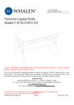
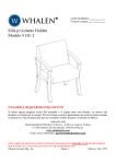
1
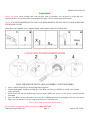
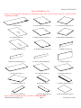
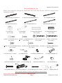
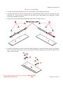
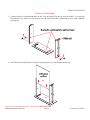
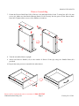
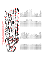
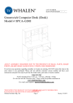
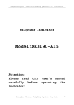
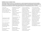
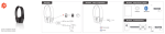
LOT NUMBER:
DATE PURCHASED: /
/
Leadenhall Collection Credenza
Model # JCS110245-D
ADULT ASSEMBLY REQUIRED DUE TO THE PRESENCE OF SMALL PARTS, SHARP
POINTS, SHARP EDGES AS RECEIVED
If you have any questions regarding assembly or if parts are missing, DO NOT return this item to the
store where it was purchased. Please call our toll-free customer service number and have your
instructions and parts list ready to provide the model name, part name or factory number:
1-866-942-5362
Pacific Standard Time: 8:30 a.m. - 4:30 p.m., Monday - Friday
Or visit our web site 24 hours a day, 7 days a week for product assistance at
www.whalenfurniture.com
Or e-mail your request to [email protected]
THIS INSTRUCTION BOOKLET CONTAINS IMPORTANT SAFETY INFORMATION.
PLEASE READ AND KEEP FOR FUTURE REFERENCE.
Whalen Furniture Mfg., Inc.
Page 1
Factory No. 15548
Model # JCS110245-D
Important Before you begin: Open, identify and count all parts prior to assembly. Lay out parts on a flat and nonabrasive surface. You will need the parts identified on page 5 and 6 of this instruction manual.
NOTE: IT IS VERY IMPORTANT TO USE GLUE WITH DOWELS. EXCESS GLUE CAN BE WIPED OFF
WITH DAMP CLOTH.
Insert Dowel at least half way by tapping lightly with a rubber mallet IF NECESSARY.
CAM LOCK SYSTEM OPERATION
HOW THE KNOCK DOWN (KD) ASSEMBLY SYSTEM WORKS
1. Screw Cam Bolt into the pre-drilled small holes on panel.
2. Connect both panels together; making sure Cam Bolt goes into pre-drilled hole on the end of panel
with Cam Lock.
3. Insert Cam Lock into pre-drilled large hole on panel. Make sure arrow on Cam Lock is pointed toward
Cam Bolt.
4. Once Cam Bolt is connected inside Cam Lock, take a Phillips screwdriver and tighten Cam Lock clockwise.
5. Plug Cam Cap into the cross slot of the Cam Locks to conceal the cam.
You are now ready to assemble the KD unit.
Please call for replacement parts or assistance: 1-866-942-5362
Whalen Furniture Mfg., Inc.
Page 2
Factory No. 15548
Model # JCS110245-D
FURNITURE POWER DISTRIBUTION CENTER
IMPORTANT SAFETY INSTRUCTIONS
Carefully Read all Instructions installing and operating fixture
IF YOU HAVE ANY QUESTIONS REGARDING THE PROPER INSTALLATION
CONSULT A QUALIFIED ELECTRICIAN
TO REDUCE THE RISK OF FIRE, ELECTRICAL SHOCK OR
INJURE TO PERSONS, PLEASE FOLLOW THE NEXT:
• Use only insulated staples or plastic ties to secure the cords.
• Route and secure cords so that they will not be pinched or damage when the cabinet is pushed
to the wall.
• Make sure cord is not pinched between cabinet and floor.
• Use the unit for indoor use only.
• Do not use an extension cord to connect this unit to a wall outlet, use power strip with integral
over current protection to supply other electrical devices or accessories in cabinet.
• This unit must be plugged into a properly grounded outlet.
• The socket-outlet shall be installed near the equipment and shall be easily accessible.
• Maximum load of connected equipment cannot exceed a total of 10 amps.
• Do not open or disassemble this unit for any reason.
SAVE THESE INSTRUCTIONS
Please call for replacement parts or assistance: 1-866-942-5362
Whalen Furniture Mfg., Inc.
Page 3
Factory No. 15548
Model # JCS110245-D
Furniture Power Distribution Unit User Guide
Please read this user guide before installing and using your power distribution center.
INTRODUCTION
The integrated 3-Port USB 2.0 Desktop Hub offers 480
Mbps high transmission rate and can connect up to three
devices, such as a digital camera, MP3 player, cell
phone or wireless mouse. With plug-and-play capability,
you can add a device without restarting your computer.
INSTALLATION
Connect the USB cable to the bottom of the hub and
then to your computer. The hub installs automatically. If
necessary, follow the onscreen instructions to complete
installation. Once the default drivers are installed, the
red LED status indicator light will glow and you can
connect devices to the hub.
NOTES
• To reach USB 2.0 high speed, your computer or host
adapter card must support USB 2.0. This hub is also
backwards compatible with USB 1.1.
• When using the hub with a computer that has a
version 1.1 USB interface, all of the devices attached
to the hub will run at USB 1.1 speed.
Product: Furniture Power Distribution Unit
Model No: UE-UL001
Company: Whalen Furniture Mfg., Inc.
NOTE: This equipment has been tested and found to
comply with the limits for Class B digital device,
pursuant to part 15 of the FCC Rules. These limits are
designed to provide reasonable protection against
harmful interference in a residential installation. This
equipment generates, uses and can radiate radio
frequency energy and, if not installed and used in
accordance with the instructions, may cause harmful
interference to radio or television reception. However,
there is no guarantee that interference will not occur in a
particular installation.
If this equipment does cause harmful interference to
radio or television reception, which can be determined
by turning the equipment off and on, the user is
encouraged to try to correct the interference by one or
more of the following measures:
• Reorient or relocate the receiving antenna.
• Increase the separation between the equipment and
receiver.
• Connect the equipment into an outlet on a circuit
different from that to which the receiver is connected.
• Consult the dealer or an experienced radio/TV
technician for help.
This device complies with Part 15 of the FCC Rules.
Operation is subject to the following two conditions: (1)
This device may not cause harmful interference, and (2)
this device must accept any interference received,
including interference that may cause undesired
operation.
SYSTEM REQUIRMENTS
•
•
•
•
•
•
Windows® 98SE/ME/2000/XP/Vista /7
Pentium 233 MHz or higher
At least 64 MB RAM
Available USB port
Mac OS 9 or later for USB 1.1 mode
Mac OS X or later for USB 2.0 mode
WARNINGS
! Your hub automatically shut off any port with a low
or excessive current.
! If USB Hub Current Limit Exceeded appears on your
screen, disconnect the affected USB device, click
Reset on the screen, and reconnect the device.
! If one of your hub ports is disabled, but USB Hub
Current Limit Exceeded does not appear:
• Disconnect and reconnect the affected device.
• If the port still does not work, disconnect the hub
and the device, and then reconnect.
! Keep your desktop hub dry; if it gets wet, wipe it dry
immediately.
! Do not modify or tamper with your desktop hub’s
internal components. It may cause a malfunction and
invalidate its warranty.
! Modifications not approved by the party responsible
for compliance could void user’s authority to operate
the equipment.
Please call for replacement parts or assistance: 1-866-942-5362
Whalen Furniture Mfg., Inc.
Page 4
Factory No. 15548
Model # JCS110245-D
Parts and Hardware List
Please read completely through the instructions and verify that all parts listed are present before
beginning assembly.
A- Desk Top (1)
B- Left Pedestal Left Side (1)
D- Left Back Panel (1)
E- Right Pedestal Left Side (1)
G- Right Back Panel (1)
J- Bottom Front Molding (2)
M- Keyboard Tray (1)
P- Right Door Panel (1)
S- Drawer Left Side (2)
H- Pedestal Bottom Panel (2)
K- Bottom Side Molding (4)
N- Adjustable Shelf (2)
Q- Drawer Front (2)
T- Drawer Right Side (2)
Please call for replacement parts or assistance: 1-866-942-5362
Whalen Furniture Mfg., Inc.
Page 5
C- Left Pedestal Right Side (1)
F- Right Pedestal Right Side (1)
I- Middle Crossbar (2)
L- Modesty Panel (1)
O- Left Door Panel (1)
R- Drawer Back Panel (2)
U- Drawer Bottom Panel (2)
Factory No. 15548
Model # JCS110245-D
Parts and Hardware List
Please read completely through the instructions and verify that all parts listed are present before
beginning assembly.
V- Keyboard Tray Left Slides (1)
CR- Right Slide Track (2)
(1) Cam Lock
(31+1 extra)
W- Keyboard Tray Right Slides (1)
CL- Left Slide Track (2)
DL- Left Slide Runner (2)
DR- Right Slide Runner (2)
(2) Cam Bolt
(31+1 extra)
(3) Large Wood Dowel
(18+1 extra)
(4) Small Wood Dowel
(8+1 extra)
(5) M3.5 x 12 mm Zinc Screw (6) M3.5 x 12 mm Black Screw (7) M5 x 30 mm Screw (8) M5 x 38 mm Screw
(8+1 extra)
(24+1 extra)
(12+1 extra)
(8+1 extra)
(9) M3.5 x 12 mm Pan Head Screw (10) M5 x 14 mm Pan Head Screw (11) M3 x 19 mm Ring Shank Screw
(26+1 extra)
(8+1 extra)
(40+2 extra)
(12) Cam Cap (7+1 extra)
(13) Shelf Pin (8)
(16) Floor Protector (8+1 extra)
(14) Plastic Connector (4)
(17) Door Hinge (4)
(20) Handle Bolt (6) (21) Power Center (1)
(15) Plastic Bracket (4)
(18) Drawer Handle (2)
(22) 22 mm Screw (6+1 extra)
(19) Door Knob (2)
Glue (1)
Touch-up Pen (1)
Tools required: Phillips screwdriver and Hammer (not provided).
Please call for replacement parts or assistance: 1-866-942-5362
Whalen Furniture Mfg., Inc.
Page 6
Factory No. 15548
Model # JCS110245-D
Drawer Assembling
1. Unpack the unit and confirm that you have all the hardware and required parts listed.
2. Using the pilot holes as a guide, align and attach Left Slide Runner (DL) to Drawer Left Side (S) using
three M3.5 x 12 mm Screws (6). Make sure the roller end of Slide Runner faces backward. Tightly
fasten with a Phillips screwdriver.
3. Repeat last step to attach Right Slide Runner (DR) to Drawer Right Side (T).
4. Using the pilot holes as a guide, attach two Plastic Brackets (15) onto the Drawer Front (Q) with four
M5 x 14 mm Pan Head Screws (10). Be sure the tabs of Plastic Bracket point towards the short end of
drawer front vertically.
Please call for replacement parts or assistance: 1-866-942-5362
Whalen Furniture Mfg., Inc.
Page 7
Factory No. 15548
Model # JCS110245-D
Drawer Assembling
5. Connect Drawer Left and Right Side (S and T) to the Drawer Front (Q) using four M3.5 x 12 mm Pan
Head Screws (9). Make sure the grooves line up with each other. Tighten the screws with a Phillips
screwdriver.
T
Q
S
6. Slide Drawer Bottom Panel (U) all the way into the grooves with finished surface up.
Please call for replacement parts or assistance: 1-866-942-5362
Whalen Furniture Mfg., Inc.
Page 8
Factory No. 15548
Model # JCS110245-D
Drawer Assembling
7. Fasten the Drawer Back Panel (R) to Drawer Left and Right Sides (S and T) using four M5 x 38 mm
screws (8). Make sure that Drawer Bottom Panel (U) fits securely into the groove of the Drawer Back
Panel (R). Tighten all the screws with a Phillips screwdriver.
8. Turn the assembled drawer upright.
9. Attach one Drawer Handle (18) to the outside of Drawer Front (Q) using two Handle Bolts (20)
provided.
10. Repeat the same process to assemble the other drawer.
Q
Please call for replacement parts or assistance: 1-866-942-5362
Whalen Furniture Mfg., Inc.
Page 9
Factory No. 15548
Model # JCS110245-D
Assembly Instructions
11. Using the pilot holes as a guide, align and attach two Left Slide Tracks (CL) to the Left and Right
Pedestal Left Side Panels (B and E) respectively using three M3.5 x 12 mm Screws (6) through the
small holes on the Track into place. Make sure the roller end of Slide Track facing forward. Tightly
fasten with a Phillips screwdriver.
12. Repeat last step to attach Right Slide Tracks (CR) to the Left and Right Pedestal Right Panel (C and F).
13. Insert two Small Wood Dowels (4) into the inner holes of the Bottom Side Molding (K) and attach to
the bottom of Pedestal Side Panels (B, C, E and F) using three M5 x 30 mm Screws (7) in each. Make
sure the bottom edges are flush.
14. Screw 3 Cam Bolts (2) into the designated small holes on each Pedestal Side Panel (B, C, E and F) as
shown in the illustration.
15. Gently tap two Floor Protectors (16) onto the bottom of each Pedestal Side Panel (B, C, E and F). Make
sure the Floor Protectors rest on the center of side panel for avoiding any damage or crack.
2
7
B/C/E/F
6
6
4
CR
C/F
B/E
K
16. Screw 2 Cam Bolts (2) all the way into the designated
small holes on one Bottom Front Molding (J) as shown.
17. With the pilot holes as a guide, fasten two Plastic
Connectors (14) to the Bottom Front Molding (J) with
the right-angle side facing the short end vertically,
using M3.5 x 12 mm Pan Head Screws (9).
18. Insert one Large Wood Dowel (3) into the middle
large hole of the Bottom Front Molding (J) and attach
to one Pedestal Bottom Panel (H) using 2 Cam Locks (1)
(Refer to page #2 on Cam Lock system operation
supplement). Make sure the Cam Locks will face floor.
9
2
2
J
3
19. Repeat the same procedure with the other Bottom
Front Molding (J) and Pedestal Bottom Panel (H).
Please call for replacement parts or assistance: 1-866-942-5362
Whalen Furniture Mfg., Inc.
Page 10
Factory No. 15548
Model # JCS110245-D
Assembly Instructions
20. Pick up assembled Bottom Panel (H) and attach to the Left Pedestal Left Panel (B) using one Large
Wood Dowel (3) and two Cam Locks (1). Make sure the bottom edges are flush with each other.
Proceed to secure the Bottom Front Molding (J) in place by screwing one M3.5 x 12 mm Pan Head
Screw (9) through the Plastic Connector (14).
21. Align and attach one Middle Crossbar (I) to the Left Pedestal Left Panel (B) using one Large Wood
Dowel (3) and one Cam Lock (1). Ensure the Cam Locks point towards bottom of unit.
22. Repeat last two steps with Right Pedestal Right Panel (F).
I
I
J
J
1
9
1
H
9
H
3
3
1
1
3
B
3
F
23. Repeat the same procedure to attach Left Pedestal Right Panel (C) and Right Pedestal Left Panel (E) to
the other end of last assemblies respectively.
3
3
1
3
1
3
1
1
9
Please call for replacement parts or assistance: 1-866-942-5362
Whalen Furniture Mfg., Inc.
Page 11
9
Factory No. 15548
Model # JCS110245-D
Assembly Instructions
24. Pick up Keyboard Tray Slides (V and W) and separate the Slide Runners for later step. Extend the Slide
Runner all the way forward. Press the plastic release lever of the slides up and pull the Slide Runner
complete out.
25. Attach separated Slide Tracks to the Left Pedestal Right Panel (C) and Right Pedestal Left Panel (E)
respectively with three M3.5 x 12 mm Pan Head Screws (9) per slide track. Ensure the opening of Slide
Track facing front of the unit.
26. Insert and screw four Cam Bolts (2) all the way into the designated small holes on Left Pedestal Right
Panel (C) and Right Pedestal Left Panel (E) as shown in the illustration.
F
B
W
2
V
2
9
C
E
27. Attach Modesty Panel (L) between the assembled Left and Right Pedestal using four Cam Locks (1)
and two Large Wood Dowels (3). (Refer to page #2 on Cam Lock system operation supplement). Make
sure the long edge with holes of Modesty Panel is up.
C
B
3
L
1
E
F
Please call for replacement parts or assistance: 1-866-942-5362
Whalen Furniture Mfg., Inc.
Page 12
Factory No. 15548
Model # JCS110245-D
Assembly Instructions
28. Separate the Back Cover from the Power Center (21) and set aside for later use.
29. Feed the USB cable and wire of Power Center (21) through the cutout of the Desk Top (A) and push
into the cutout from top of Desk Top. At the bottom side of top panel, fit the separated Back Cover onto
the Power Center properly and secure it in place with six 22 mm Screws (22) through the countersunk
holes on the Back Cover. Make sure the USB cable and wire are not pinched.
30. Screw eleven Cam Bolts (2) all the way into the designated small holes on the Desk Top (A) as shown.
22
22
A
2
21
31. Insert the six Large Wood Dowels (3) into the top holes of the assembled unit as a guide. DO NOT put
dowels into the Cam Bolt holes. Position Desk Top (A) onto the inserted Wood Dowels (3) with the
Power Center (21) located at back side and attach in place by engaging 11 Cam Locks (1). (Refer to
page #2 on Cam Lock system operation supplement).
A
C
B
B/C/E/F/L
Please call for replacement parts or assistance: 1-866-942-5362
Whalen Furniture Mfg., Inc.
Page 13
Factory No. 15548
Model # JCS110245-D
Assembly Instructions
32. Now go back and tighten all Cam Locks and Screws, make sure all the parts are tight and there are no
gaps between the parts, this will help keep the unit square.
33. Align and attach Left and Right Back Panels (D and G) onto the assembled unit with stained surface
facing backward. Make sure the margins along all edges of Back Panels are equal. Gently hammer the
M3 x 19 mm Ring Shank Screws (11) through the pre-drilled holes on the Back Panels.
NOTE: We recommend attaching back panel with Ring Shank Screws at the corners first.
A
D
G
C
34. Using the pilot holes as a guide, attach separated Left and Right Slide Runners (V and W) to the bottom
of Keyboard Tray (M) using four M3.5 x 12 mm Pan Head Screw (9) through the metal tabs.
Please call for replacement parts or assistance: 1-866-942-5362
Whalen Furniture Mfg., Inc.
Page 14
Factory No. 15548
Model # JCS110245-D
Left Pedestal Assembling
35. Extend the Ball Bearing Slide Tracks (V and W) on the pedestal side panels all the way forward (including ball
bearing cart). Align the Slide Runners on the Keyboard Tray (M) with the Slide Tracks and push the tray
carefully inside until it stops.
NOTE: If they do not go smoothly, please take out and repeat the step. If you need to remove the keyboard tray,
please pull the tray all the way out, then simultaneously push the plastic release lever of the ball bearing slides up
on one side and down on the other side, and then pull it completely out.
36. To insert the assembled storage drawers into place, tip the front of drawers down and drop the rollers of the
drawers Slide Runners behind the rollers of Slide Tracks on the unit. Lift the front of the drawer up and slide it
into the unit.
A
M
Q
B
37. Extend the Door Hinges (17) and rest the Hinge Cups onto the cutouts of Door Panels (O and P). Secure the Door
Hinges (17) in place by using two M3.5 x 12 mm Zinc Screws (5) in each.
38. Pick up the Left Door Panel (O) and fasten the Hinge Bases onto the Left Pedestal Left Side Panel (B) with the
enclosed self-tapping bolts. DO NOT fully tighten the bolts.
39. Close the Door Panel (O) to double check the alignment. If you find that the door need to be adjusted slightly,
please refer to the door hinge sticker on the door panel and turn the appropriate screws for a perfectly aligned
door. After adjusted tighten the screws on Hinge Base to lock the hinges in place.
40. Repeat the same procedure to attach Right Door Panel (P) in place.
41. Attach the Door Knobs (19) to the outside of Door Panels using the Handle Bolts (20) provided.
42. Put the rubber bumper onto each Shelf Pin (13). Open the door and insert the other end of Shelf Pins in your
desired location inside the compartment. Make sure you place the Shelf Pins in the same level so the shelf is not
tilted. Rest the Adjustable Shelf (N) onto the Shelf Pins installed.
43. Plug Cam Caps (12) onto the visible Cams Locks (1) to conceal the Cams.
5
O/P
O/P
17
N
F
P
N
B
O
19
20
N
Please call for replacement parts or assistance: 1-866-942-5362
Whalen Furniture Mfg., Inc.
Page 15
Factory No. 15548
Model # JCS110245-D
Care and Maintenance
z
z
z
z
z
z
z
z
z
z
Use a soft, clean cloth that will not scratch the surface when dusting.
Use of furniture polish is not necessary. Should you choose to use polish, test first in an inconspicuous area.
Using solvents of any kind on your furniture may damage your furniture’s finish.
Never use water to clean your furniture as it may cause damage to the finish.
Always use coasters under beverage glasses and flowerpots.
Liquid spills should be removed immediately. Using a soft clean cloth, blot the spill gently. Avoid rubbing.
Always use protective pads under hot dishes and plates. Heat can cause chemical changes that may create
spotting within the furniture finish.
Stains or marks from crayons or ink markers will be difficult to remove.
In the event that your furniture is stained or otherwise damaged during use, we recommend that you call a
professional to repair your furniture.
Check bolts/screws periodically and tighten them if necessary.
Further advice about wood furniture care
It is best to keep your furniture in a climate-controlled environment. Extreme temperature and humidity
changes can cause fading, warping, shrinking and splitting of wood. It is advised to keep furniture away from
direct sunlight as sun may damage the finish.
Proper care and cleaning at home will extend the life of your purchase. Following these important and helpful
tips will enhance your furniture as it ages.
A Touch-up Pen has been provided to repair any small nicks or scratches that may occur during assembly or
shipping.
We hope you enjoy your purchase for many years.
Thank you for your purchase!
QUALITY GUARANTEE
We are confident that you will be delighted with your Whalen Furniture purchase.
Should this product be defective in workmanship or materials or fail under normal use, we will repair or
replace it for up to one (1) year from date of purchase. Every Whalen Furniture product is designed to meet
your highest expectations. We guarantee that you will immediately see the value of our fine furniture.
This warranty gives you specific legal rights and you may also have other rights which vary from province to
province (state to state).
Customer Service: 1-866-942-5362
8:30 a.m. - 4:30 p.m. PST, Monday to Friday
www.whalenfurniture.com
Please call for replacement parts or assistance: 1-866-942-5362
Whalen Furniture Mfg., Inc.
Page 16
Factory No. 15548
*JCS110245-D-1-DT
JCS110245 D 1 DT
*JCS110245-D-2-LPLS
*JCS110245-D-3-LPRS
*JCS110245-D-4-LBP
*JCS110245-D-5-RPLS
*JCS110245-D-6-RPRS
*JCS110245-D-7-RBP
*JCS110245-D-8-PBP
*JCS110245-D-9-MC
*JCS110245-D-10-BFM
*JCS110245-D-11-BSM
*JCS110245-D-12-MP
*JCS110245-D-13-KT
*JCS110245-D-14-AS
*JCS110245-D-15-LDP
*JCS110245-D-16-RDP
*JCS110245-D-17-DF
*JCS110245-D-18-DBP
*JCS110245-D-19-DLS
*JCS110245-D-20-DRS
*JCS110245-D-21-DB
*JCS110245-D-22-DH
*JCS110245-D-23-DK
*JCS110245-D-24-KTLS
*JCS110245-D-25-KTRS
*JCS110245-D-26-LST
Desk Top
Left Pedestal Left Side
Left Pedestal Right Side
Left Back Panel
Right Pedestal Left Side
Right Pedestal Right Side
Right Back Panel
Pedestal Bottom Panel
Middle Corssbar
Bottom Front Molding
Bottom Side Molding
Modesty Panel
Keyboard Tray
Adjustable Shelf
Left Door Panel
Right Door Panel
Drawer Front
Drawer Back Panel
Drawer Left Side
Drawer Right Side
Drawer Bottom
Drawer Handle
Door Knob
Keyboard Tray Left Slides
Keyboard Tray Right Slides
Left Slide Track
*JCS110245-D-27-RST
JCS110245 D 27 RST
*JCS110245-D-28-LSR
*JCS110245-D-29-RSR
*JCS110245-D-30-CL
*JCS110245-D-31-CB
*JCS110245-D-32-LWD
*JCS110245-D-33-SWD
*JCS110245-D-34-M3.5x12ZS
*JCS110245-D-35-M3.5x12BS
*JCS110245-D-36-M5x30S
*JCS110245-D-37-M5x38S
*JCS110245-D-38-M3.5x12PHS
*JCS110245-D-39-M5x14PHS
*JCS110245-D-40-M3x19RSS
*JCS110245-D-41-CC
*JCS110245-D-42-SP
*JCS110245-D-43-PC
*JCS110245-D-44-PB
*JCS110245-D-45-HB
*JCS110245-D-46-22S
*JCS110245-D-47-FP
*JCS110245-D-48-G
*JCS110245-D-49-TUP
*JCS110245-D-50-DH
*JCS110245-D-51-PC
*JCS110245-D-CH
Leadenhall Collection Credenza (JCS110245-D)
IF YOU NEED TO ORDER ANY PARTS PLEASE USE THE LIST BELOW
Floor Protector
Glue
Touch-up Pen
Door Hinge
Power Center (UE-UL001)
Complete Hardware
M3.5 x 12 mm Zinc Screw
M3.5 x 12 mm Blace Screw
M5 x 30 mm Screw
M5 x 38 mm Screw
M3.5 x 12 mm Pan Head Screw
M5 x 14 mm Pan Head Screw
M3 x 19 mm Ring Shank Screw
Cam Cap
Shelf Pin
Plastic Connector
Plastic Bracket
Handle Bolt
22 mm Screw
Right Slide Track
Left Slide Runner
Right Slide Runner
Cam Lock
Cam Bolt
Large Wood Dowel
Small Wood Dowel