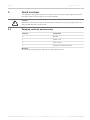
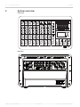
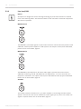
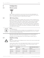
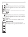
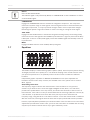
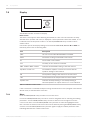
1
PM 502
en | User manual
PM 502
Table of Contents | en
3
Table of contents
1
Safety
4
2
Quick overview
7
2.1
Shipping contents and warranty
7
3
System overview
8
4
Installation
9
5
Connection
10
5.1
Mains input
10
5.2
Audio inputs
10
5.2.1
Mono inputs (MIC/LINE)
10
5.2.2
Stereo inputs
11
5.3
Audio outputs
12
5.3.1
Speaker connection
12
5.3.2
Line level/USB
14
5.3.3
Headphone
15
15
5.4
Other connections
5.4.1
USB data storage
15
5.4.2
FX switch
15
6
Configuration
16
6.1
Phantom power
16
6.2
100 V Direct Drive
16
6.3
Amplifier routing
16
6.4
Speaker processing (LPN)
17
6.5
AUX mode
17
6.6
Locking
18
6.7
Microphone processing (TALK OVER)
19
7
Operation
20
7.1
Mono input
20
7.2
Stereo input
22
7.3
FX
23
7.4
AUX
24
7.5
MASTER
24
7.6
Microphone processing
24
7.7
Equalizer
25
7.8
Display
26
7.8.1
Menu
26
7.9
Indicators
30
7.10
Headphone volume
31
8
Maintenance
32
9
Technical data
33
9.1
Dimensions
37
9.2
Circuit diagram
38
10
Appendices
39
10.1
System examples
39
10.2
Pin assignments
43
Bosch Sicherheitssysteme GmbH
User manual
15-May-14 | 02 | F01U297804
4
en | Safety
1
PM 502
Safety
Danger!
The lightning symbol inside a triangle notifies the user of high-voltage, uninsulated lines and
contacts inside the devices that could result in fatal electrocution if touched.
Warning!
!
An exclamation mark inside a triangle refers the user to important operating and service
instructions in the documentation for the equipment.
1.
Read these safety notes.
2.
Keep these safety notes in a safe place.
3.
Heed all warnings.
4.
Observe all instructions.
5.
Do not operate the device in close proximity to water.
6.
Use only a dry cloth to clean the unit.
7.
Do not cover any ventilation slots. Always refer to the manufacturer's instructions when
installing the device.
8.
Do not install the device close to heaters, ovens, or other heat sources.
9.
Note: The device must only be operated via the mains power supply with a safety ground
connector. Do not disable the safety ground connection function of the supplied power
cable. If the plug of the supplied cable does not fit your mains socket, please contact
your electrician.
10. Ensure that it is not possible to stand on the mains cable. Take precautions to ensure the
mains cable cannot become crushed, particularly near the device connector and mains
plug.
11. Only use accessories/extensions for the device that have been approved by the
manufacturer.
12. Unplug the device if there is risk of lightning strike or in the event of long periods of
inactivity. However, this does not apply if the device is to be used as part of an
evacuation system!
13. Have all service work and repairs performed by a trained customer service technician
only. Service work must be carried out immediately following any damage such as
damage to the mains cable or plug, if fluid or any object enters the device, if the device
has been used in rain or become wet, or if the device has been dropped or no longer
works correctly.
14. Please ensure that no dripping water or spray can penetrate the inside of the device. Do
not place any objects filled with fluids, such as vases or drinking vessels, on top of the
device.
15-May-14 | 02 | F01U297804
User manual
Bosch Sicherheitssysteme GmbH
PM 502
Safety | en
5
15. To ensure the device is completely free of voltage, unplug the device from the power
supply.
16. When installing the device, ensure that the plug is freely accessible.
17. Do not place any sources of open flame, such as lit candles, on top of the device.
18. This PROTECTION CLASS I device must be connected to a MAINS socket with a safety
ground connection.
Caution!
Use only manufacturer-approved carts, stands, brackets, or tables that you acquired together
with the device. When using carts to move the device, make sure the transported equipment
and the cart itself cannot tip over or cause injury or material damage.
IMPORTANT SERVICE INFORMATION
Caution!
This service information is for use by qualified service personnel only. To avoid the risk of
!
electric shock, do not perform any maintenance work that is not described in the operating
instructions unless you are qualified to do so. Have all service work and repairs performed by
a trained customer service technician.
1.
Repair work on the device must comply with the safety standards specified in EN 60065
(VDE 0860).
2.
A mains isolating transformer must be used during any work for which the opened device
is connected to and operated with mains voltage.
3.
The device must be free of any voltage before performing any alterations with upgrade
sets, switching the mains voltage, or performing any other modifications.
4.
The minimum distance between voltage-carrying parts and metal parts that can be
touched (such as the metal housing) or between mains poles is 3 mm, and must be
observed at all times.
5.
The minimum distance between voltage-carrying parts and circuit parts that are not
connected to the mains (secondary) is 6 mm, and must be observed at all times.
6.
Special components that are marked with the safety symbol in the circuit diagram (note)
must only be replaced with original parts.
7.
Unauthorized changes to the circuitry are prohibited.
8.
The protective measures issued by the relevant trade organizations and applicable at the
place of repair must be observed. This includes the properties and configuration of the
workplace.
9.
Observe the guidelines with respect to handling MOS components.
Danger!
SAFETY COMPONENT (MUST BE REPLACED BY ORIGINAL PART)
Notice!
Due to line current harmonics, we recommend that you contact your supply authority before
connection.
Bosch Sicherheitssysteme GmbH
User manual
15-May-14 | 02 | F01U297804
6
en | Safety
PM 502
Old electrical and electronic appliances
Electrical or electronic devices that are no longer serviceable must be collected separately and
sent for environmentally compatible recycling (in accordance with the European Waste
Electrical and Electronic Equipment Directive).
To dispose of old electrical or electronic devices, you should use the return and collection
systems put in place in the country concerned.
15-May-14 | 02 | F01U297804
User manual
Bosch Sicherheitssysteme GmbH
PM 502
Quick overview | en
7
Quick overview
2
Your PM 502 is designed so that you can easily set it up and start using it right away. Follow
the steps on the next few pages to set up your PM 502.
Caution!
!
2.1
Read all the instructions in this document and the safety notes starting on page 4 before you
plug your PM 502 into a power outlet.
Shipping contents and warranty
Quantity
Component
1
PM 502
1
Power cord
1
User manual
1
Important safety instructions
Warranty
For information regarding the warranty, see www.dynacord.com
Bosch Sicherheitssysteme GmbH
User manual
15-May-14 | 02 | F01U297804
8
3
en | System overview
PM 502
System overview
Front view
Rear view
15-May-14 | 02 | F01U297804
User manual
Bosch Sicherheitssysteme GmbH
PM 502
Installation | en
4
9
Installation
Always place the PM 502 on an even surface to allow for sufficient airflow during the
operation. The device is equipped with an electronically controlled fan to protect the power
amplifier against thermal overload. The direction of the airflow is right to left. Do not cover the
top and side ventilation slots, otherwise, the PM 502 will automatically reduce its output
power or it will go into protect mode to prevent thermal overload. If the PM 502 goes into
protect mode to help prevent damage to the product, regular operation will be suspended
until the product has cooled sufficiently to resume normal operation. Always ensure adequate
cooling and appropriate shade to keep the ambient temperature around the product within
the specified operating temperature range.
Notice!
Protection foil
Carefully remove the protection foil from the front panel before using the PM 502. Do not
remove any knobs from the front panel, the foil can be easily removed without having to
detach the knobs on the control surface.
Before connecting to the mains supply, please make sure that the device matches the voltage
and frequency of your local mains supply. Check the label on the back of the unit.
For a secure connection the speaker outputs CH 1/2 on the back panel of the PM 502 are
provided through professional standard high-performance speakON or Euroblock connectors.
Using the RMK 502 Rack mount kit
The RMK 502 Rack mount kit allows the PM 502 to be securely placed into a 19 inch rack,
desk or table without covering the ventilation slots. When installing the PM 502 into a rack,
please ensure sufficient ventilation. A minimum distance of at least 2 HU above the mixer and
1 HU below the mixer is the minimum space requirement.
Caution!
!
Use only the supplied screws M4x10. Using longer screws can lead to severe damage of
internal parts.
Bosch Sicherheitssysteme GmbH
User manual
15-May-14 | 02 | F01U297804
10
en | Connection
PM 502
5
Connection
5.1
Mains input
The PM 502 receives its power supply via the IEC mains input. Only the provided power cord
may be used. Connect the device only to a mains network that corresponds to the
requirements on the back plate.
5.2
Audio inputs
Caution!
Please, make sure to set the input channel VOLUME controls or at least the MASTER or AUX
!
VOLUME controls to their minimum position before connecting an external sound source to
any input of the PM 502. This will save you, your audience, and the equipment from
unnecessary discomfort.
5.2.1
Mono inputs (MIC/LINE)
Electronically balanced MIC/LINE inputs 1 to 5 for the connection of a monaural line level
signal source or a microphone. Generally, any type of XLR-type microphone can be connected
as long as its pin assignment is in accordance to the diagram shown in section Pin
assignments, page 43.
The connection of balanced or unbalanced signal sources can also be established through
monaural or stereo jacks, assigned according to the the illustrations in section Pin
assignments, page 43. If the device that you want to connect has a balanced output stage,
the use of balanced cables with stereo jacks is preferable. This type of connection is less
sensitive to the introduction of external noise or HF interference.
Notice!
Please, do not connect E-guitars or E-basses with passive, high impedance outputs directly to
a MIC/LINE input. The MIC/LINE inputs of the PM 502, as with the line level inputs of mixers
from other manufacturers, are designed for the connection of the relatively low source
impedance of electronic instruments. The reproduction of the instrument’s original sound
characteristics will be unsatisfactory. Connect those instruments using a special transformer
or pre-amplifier with very high input impedance. Musical instruments with an active electronic
output (battery-powered) can be connected without any problems.
15-May-14 | 02 | F01U297804
User manual
Bosch Sicherheitssysteme GmbH
PM 502
5.2.2
Connection | en
11
Stereo inputs
Electronically balanced inputs for the connection of musical instruments with stereo output,
like keyboards, drum machines, E-guitars and E-basses with an active output as well as all
other equivalent sound sources with high level outputs, like additional mixing consoles, FX
units, CD players, etc. The stereo LINE input is meant for balanced or unbalanced sound
sources with levels between -20 dBu and +26 dBu.
Using jacks
For the connection of external devices to inputs 6, 7 or 8 you can use monaural or stereo
jacks, which are in accordance to the diagram in section Pin assignments, page 43. If the
device that you want to connect has a balanced output stage, the use of balanced cables with
stereo jacks is preferable. This type of connection is less sensitive to the introduction of
external noise or HF interference. If you want to connect a monaural sound source to a stereo
input channel, use the L/MONO input. The signal is routed internally to both channels.
Using RCA plugs
The RCA inputs CD 1 and CD 2 are connected in parallel to the phone inputs STEREO 1 or
STEREO 2. It is not recommended to connect signal sources to phone and RCA inputs at the
same time.
Using the USB interface
When using the USB interface as an audio input, the stereo signal is routed to STEREO 3. It is
not recommended to connect a signal source to the STEREO 3 inputs at the same time.
Notice!
Always check the audio volume setting in your operating system after connecting the PM 502
to your PC. For the best signal-to-noise ratio the volume setting of your PC should be set to
maximum level.
Bosch Sicherheitssysteme GmbH
User manual
15-May-14 | 02 | F01U297804
12
en | Connection
PM 502
5.3
Audio outputs
5.3.1
Speaker connection
Danger!
The arrow symbol next to the speaker output connectors indicates the presence of touch
sensitive voltages, which can cause harm to body and health. Please, be sure to adhere to
corresponding notes and instructions in this owner’s manual when establishing speaker
connections.
Caution!
!
Do not connect low-Z and high-Z speakers simultaneously.
Caution!
!
The minimum load in Low-Z mode is 4 Ω per channel.
The PM 502 allows connecting
•
low impedance (low-Z) speakers (e.g. 4 Ω or 8 Ω) or
•
high impedance (high-Z) speakers in Direct Drive mode (see section 100 V Direct Drive,
page 16 for details).
Low-Z speakers can be connected via speakON or Euroblock connectors. High-Z speakers shall
be connected via the Euroblock connectors only, please refer to the following sections.
speakON
The PM 502 is equipped with professional speakON high-performance connectors, offering
electrical and mechanically secure connection, which complies to all security regulations. It
also allows the use of high quality speaker cables with diameters of 4 x 2.5 mm2. The pin
assignment of these sockets is 1+ (hot) and 1- (cold).
Notice!
Using original Neutrik connectors (e.g. NL4FC) is recommended for optimal audio quality.
Notice!
Using passive subwoofers, which sum the input signal of the left and right channel, is not
possible for technical reasons.
15-May-14 | 02 | F01U297804
User manual
Bosch Sicherheitssysteme GmbH
PM 502
Connection | en
13
Euroblock connector in low-Z mode
When the Direct Drive mode is not activated, the Euroblock connector CH 1/2 +/- is in parallel
to the speakON connectors CH 1/2 and can be used alternatively.
Figure 5.1: Connection of low impedance speakers
Euroblock connector in high-Z mode
When the Direct Drive mode is activated, use pin + of CH 1 and pin – of CH 2 to connect the
100 V loudspeaker line, see following illustration.
Figure 5.2: Connection of a 100 V speaker line
Notice!
Make sure to bridge pins 1- and 2+ of the Euroblock connector.
Bosch Sicherheitssysteme GmbH
User manual
15-May-14 | 02 | F01U297804
14
en | Connection
5.3.2
PM 502
Line level/USB
Notice!
All outputs are designed in Ground Sensing technology to prevent the induction of external
noise, even with long cables. Use balanced cables for the connection of external components
whenever it is possible.
MASTER A L/R
The MASTER A, L/R output signals are post master A volume control and mainly meant to feed
additional, external power amplifiers or DSP systems. The output is stereo/mono-switchable,
please refer to section Menu, page 26.
MASTER B L/R
The MASTER B, L/R outputs the L/R master audio signal is present that can be used for
additional monitoring, side fill and additional zone applications, or for the connection of a
delay-line or subwoofer. The output is stereo/mono switchable and also pre/post switchable.
Please refer to section Menu, page 26.
AUX OUT
This output provides connection for e.g. a power amplifier or active stage monitor speaker
systems. The AUX OUT can also be switched to master signal (pre or post) if a 3rd master out
signal is required. Please refer to section Menu, page 26.
15-May-14 | 02 | F01U297804
User manual
Bosch Sicherheitssysteme GmbH
PM 502
Connection | en
15
USB
The L/R master audio signal is always present at the USB interface. This allows using your
PC/Mac for recording while the PM 502 functions as premium A/D converter, without the need
for an external sound card.
5.3.3
Headphone
Stereo phone jack (3.5 mm) for the connection of headphones with an impedance of 32–
600 Ω. The phones output presents the master signal. The corresponding control is described
in section Headphone volume, page 31. The output is protected against short circuit.
Headphones or in ear monitor systems with an impedance below 32 Ω can be connected, in
this case the maximum reachable volume is reduced.
5.4
Other connections
5.4.1
USB data storage
Connect a USB flash drive or external hard drive to the USB port on the front panel to use the
integrated audio player of the PM 502. The external memory is scanned automatically for
suitable audio tracks (MP3 or WAV). If audio tracks are detected, the audio player dialog will
be shown in the LC-Display automatically.
Notice!
Powering external drives through USB
The USB 2.0 port of the PM 502 provides up to 500 mA to USB peripherals. Peripherals
exceeding this limit may not work properly, make sure to use an external power adaptor to
supply such devices.
5.4.2
FX switch
A jack FX SWITCH for the connection of an optionally available FS 11 (DC-FS11) footswitch
from Dynacord to switch the effect mode of the internal FX unit on or off. To enable this
function, the FX ON switch (see section FX, page 23) on the front panel has to be engaged.
Bosch Sicherheitssysteme GmbH
User manual
15-May-14 | 02 | F01U297804
16
en | Configuration
PM 502
6
Configuration
6.1
Phantom power
When condenser microphones are connected, you have to press the PHANTOM MIC 1-5
button. The microphone gets its operating voltage (+48 V DC) through the mixer. Phantom
power is activated/deactivated for all 5 MIC/LINE inputs together.
6.2
100 V Direct Drive
The 100 V Direct Drive mode of the PM 502 allows connection of 100 V loudspeaker lines in
high impedance mode (High-Z) without using output transformers. In this case the maximum
number of loudspeakers connected to an output channel is only limited by the amplifier‘s
output power. This mode should be used if the distance between the amplifier and the
speaker is larger than 50 meters (approx. 150 feet) and/or a high number of small speakers
with transformers (e.g. ceiling speakers) are used. Depending on the audio signal a 50 Hz or
70 Hz high-pass filter can be selected, the LPN filter is deactivated automatically if the 100 V
Direct Drive mode is activated.
Notice!
70 V loudspeaker lines
Next to 100 V loudspeaker lines it is possible to drive 70 V loudspeaker lines. In this case the
limiter of the channel selected for Amp Routing (e.g. MASTER A) has to be set to +3 dBu in
the OUTPUT SETTINGS LIMITERS dialog.
Please refer to section Menu, page 26, how to activate Direct Drive. When activated, the
100V DIRECT DRIVE indicator on the front panel lights green. For connecting 100 V
loudspeaker lines to the PM 502 please refer to section Speaker connection, page 12.
6.3
Amplifier routing
Caution!
!
Make sure to set both the AUX and MASTER volume controls to their minimum position before
editing the amplifier routing.
The two output channels CH 1/2 of the integrated power amplifier can be used for different
audio signals. Please refer to section Menu, page 26, how to edit the amplifier routing.
Following table lists all amplifier routings available.
Routing
Low-Z mode
High-Z mode (Direct Drive )
CH 1
CH 2
CH 1 + 2
MASTER A
Master A left
Master A right
Master A summed
MASTER B
Master B left
Master B right
Master B summed
AUX
AUX
AUX
AUX
15-May-14 | 02 | F01U297804
User manual
Bosch Sicherheitssysteme GmbH
PM 502
Configuration | en
Routing
Low-Z mode
17
High-Z mode (Direct Drive )
CH 1
CH 2
CH 1 + 2
Dual A – B
Master A summed
Master B summed
-
Dual A – AUX
Master A summed
AUX
-
Dual B – AUX
Master B summed
AUX
-
Table 6.1: Amplifier routing
6.4
Speaker processing (LPN)
The power amplifier channels of the PM 502 incorporate Low-Pass-Notch filters (LPN)
exclusively designed by DYNACORD. The LPN filter corrects the frequency and phase response
of the connected loudspeakers. This effect can not be achieved using equalizers or „BassBoosters“, because the LPN filter mainly optimizes the transient response of the connected
speaker. The result is a more powerful sound, especially when using small to medium fullrange speakers.
Please refer to section Menu, page 26, how to edit the LPN filters setting. The following table
describes the available LPN filter settings.
Setting
SPEAKER
Description
PROCESSING
indicator
HIGH
ON
In setting HIGH the LPN filter is activated, this setting is
recommended for small to medium sized loudspeakers, e.g. fullrange speakers with 12“, 8“ or smaller woofers.
MEDIUM
ON
In setting MEDIUM the LPN filter is activated, this setting is
recommended for medium to large loudspeakers, e.g. full-range
speakers with 15“ or 18“ woofers.
FLAT
OFF
In setting FLAT the LPN filter is deactivated. Use this setting for
large loudspeaker systems with more than one subwoofer.
Table 6.2: LPN filter settings
6.5
AUX mode
The signal that is to be output via AUX OUT can be selected for the particular application.
Please refer to section Menu, page 26, how to edit the AUX mode. The following table lists all
AUX modes available.
Bosch Sicherheitssysteme GmbH
User manual
15-May-14 | 02 | F01U297804
18
en | Configuration
PM 502
Setting
Signal at AUX OUT
Description
AUX-Bus
AUX
This is the default AUX mode, the signal of the AUX
bus is present at the AUX OUT output. This mode
is mainly used for monitoring. AUX is especially
preferable when monitoring and master mix need
to be completely different from each other, e.g.
when the volume setting of particular musical
instruments or vocals needs to be higher or lower
than in the master mix.
MAS A Pre
Pre Master A summed
The summed MASTER A signal is present at the
AUX OUT output. The signal is tapped pre MASTER
A volume control and therefore not affected by the
MASTER A control’s setting.
MAS A Post
Post Master A summed
The summed MASTER A signal is present at the
AUX OUT output. The signal is tapped post
MASTER A volume control and therefore affected
by the MASTER A control’s setting.
Table 6.3: AUX modes
6.6
Locking
The PM 502 allows locking certain features or parameter settings in the menu. A four digit PIN
is used to lock or unlock the device. You can use one of three predefined locking levels or
select manually which parts of the menu should be locked, please refer to the following table
for details.
Menu
Lock Mode
Level 1
FX selection in home
Level 2
Level 3
Custom
-
-
-
-
EDIT FX
-
-
X
1.
AUDIO PLAYER
-
-
-
MIC PROCESSING
-
-
X
SPEAKER PROC
-
-
X
MASTER A EQ
-
X
X
MASTER B EQ
-
-
X
AUX EQ
-
-
X
MASTER ROUTING
-
X
X
OUTPUT SETTINGS
X
X
X
DEVICE SETUP 1
-
X
X
screen
15-May-14 | 02 | F01U297804
User manual
Select the Lock Mode
“Custom” in the DEVICE
SETUP menu.
2.
Activate the key icon of all
menus to be locked.
3.
Enter the PIN in the
DEVICE SETUP menu to
lock all menus selected in
step 2.
Bosch Sicherheitssysteme GmbH
PM 502
Configuration | en
Menu
19
Lock Mode
Level 1
Level 2
Level 3
DEVICE SETUP 2
-
-
-
INFORMATION
-
-
-
Custom
Table 6.4: Locking levels (- = available, X = locked)
6.7
Microphone processing (TALK OVER)
The integrated ducker of the PM 502 reduces the level of the signals at the STEREO inputs
whenever a signal is present at the MIC/LINE inputs (above the THRESHOLD level). If there is
no MIC/LINE signal present the STEREO signal automatically returns to its preset level. Please
refer to section Menu, page 26 how to edit the TALK OVER settings.
The following diagrams illustrate the available presets. The parameters of the ducker allow
adjusting the presets for your application.
MIC/LINE
LEVEL
THRESHOLD
TIME
STEREO
LEVEL
Announcer
TIME
STEREO
LEVEL
Singer
TIME
STEREO
LEVEL
Instructor
TIME
STEREO
LEVEL
Presenter
TIME
Figure 6.1: TALK OVER presets (the illustration is not to scale)
Bosch Sicherheitssysteme GmbH
User manual
15-May-14 | 02 | F01U297804
20
en | Operation
PM 502
7
Operation
7.1
Mono input
GAIN control
Rotary control for adjusting a MIC/LINE input’s sensitivity. These controls let you optimally
adjust the incoming signals to the mixer’s internal operation level. Slight adjustments can offer
the benefits of an improved S/N-ratio and provides you with the full bandwidth of the
PM 502’s outstanding sound capabilities. The following gain setting instruction is to be used
as a guide to help achieve a good signal input level:
1.
Set the MASTER volume controls to their minimum values (counterclockwise).
2.
Set the GAIN control and the corresponding channel VOLUME control to their center
position.
3.
Connect the sound source (microphone, instrument, etc.) to the desired MIC/LINE input.
4.
Start the sound source at the highest volume level to be expected – respectively sing or
speak as loudly as possible directly (close up) into the microphone.
5.
While playing the sound source or singing into the microphone, adjust the input level
using the GAIN control, so that during the loudest part, the PK LED does not light up. This
is the basic channel setting, leaving you with at least 6 dB of headroom, i.e. you have at
least a range of 6 dB before signal clipping occurs.
If you intend to make further adjustments to the channel’s EQ setting, you should perform
steps 4 and 5 again, as changes in the sound shaping section also have an influence on the
channel’s overall level.
HI/MID/LO controls
The mixer’s EQ section allows for a broad difference in the shaping of the incoming audio
signal within three frequency bands. Turning one of the EQ level controls to the right
enhances/amplifies the corresponding frequency range while turning it to the left lowers/
attenuates the signal of that specific frequency band. Before you begin to alter the sound, all
EQ controls should be set to their neutral position, i.e. their marker points straight up (locked
in place). Try not to set the EQ controls to extreme positions. Usually, minor changes are
sufficient to produce the best results in the overall sound. You should use the natural
reproduction as a starting point and rely on your musically trained ear. The moderate use of
the MID control is the best remedy to avoid acoustical feedback. You should try to avoid using
this frequency range to an extreme level. Lowering the level in this band will provide you with
higher output and help reduce feedback. Adjust the LO control to your taste, to add more
“punch” to the sound of a kick drum or “body” to the vocals. Use the HI control in the same
way to provide cymbals and vocals with more treble for a more transparent sound.
FX control
The FX controls is used to set the amount of effect you require on that channel input to be
routed to the integrated FX effects unit. The signal path is split post VOLUME control so that
the volume setting also influences the amount of the signal that is fed to the FX unit. Using the
FX controls lets you easily assign an effect for groups of musical instruments or vocals. To
determine the desired level of the effect, you should start with the controls set at their center
and make individual adjustments from there on.
Please monitor the PK LED in the FX channels. The indicator should only light up briefly at the
occurrence of high signal peaks. If the indicator is constantly lit, you should lower the send
levels of those channels where the program peaks occur. For further information, please read
the paragraphs about the FX unit.
15-May-14 | 02 | F01U297804
User manual
Bosch Sicherheitssysteme GmbH
Operation | en
PM 502
21
AUX control
The AUX control is primarily meant for establishing an independent mix, e.g. for monitor or a
second room/zone. The signal routing is always pre VOLUME control.
PK indicator
The peak indicator plays a key role when setting input levels. The PK (peak) LED on the
PM 502 provides a visual indication of the risk of distortion before you hear it through the
connected speaker systems. The peak indicator checks the signal level pre and post of the
channel’s VOLUME control and indicates the maximum of both levels. If the PK LED blinks
frequently or lights continuously, the corresponding channel is likely to start clipping and you
will need to reduce the volume slightly. The peak LED are triggered at a level of -6 dB below
the point of distortion.
If lowering the channel VOLUME is not sufficient to reduce signal peaks, carefully turn the
GAIN control down.
Keeping an eye on the indicator during a performance is also a good idea, because some
changes in the bands dynamics or even a change in keyboard settings can easily lead to
channel clipping, resulting in the degradation of the overall sound.
VOLUME control
The VOLUME control sets the volume of the corresponding channels, resulting in a balanced
mix. The control should be positioned initially at “5”, leaving you with enough flexibility to
balance the mix. The overall volume is adjusted through the use of the master controls. Even
though the channel controls offer an additional level of +15 dB, we would like to advise you to
exceed the “8” mark only in very few exceptional cases. If the PM 502’s summing bus gets
“overloaded” with too many “high level” input channels, despite its special gain structure, the
summing amplifier could be driven into clipping.
The best signal to noise ratio can be achieved if channel volume and master volume controls
are set in the same range.
Bosch Sicherheitssysteme GmbH
User manual
15-May-14 | 02 | F01U297804
22
7.2
en | Operation
PM 502
Stereo input
GAIN switch
Use the GAIN switch for switching between high (HI) or low (LO) input signal amplification.
The default setting is LO (-5 dB), which is suitable for all high level input sources like
keyboards or CD players. HI gain should be engaged when connecting low signal level
instruments like bass or guitar.
HI/MID/LO control
The mixer’s EQ section allows for a broad difference in the shaping of the incoming audio
signal within three frequency bands. Turning one of the EQ level controls to the right
enhances/amplifies the corresponding frequency range while turning it to the left lowers/
attenuates the signal of that specific frequency band. Before you begin to alter the sound, all
EQ controls should be set to their neutral position, i.e. their marker points straight up (locked
in place). Try not to set the EQ controls to extreme positions. Usually, minor changes are
sufficient to produce the best results in the overall sound. You should use the natural
reproduction as a starting point and rely on your musically trained ear. The moderate use of
the MID control is the best remedy to avoid acoustical feedback. You should try to avoid using
this frequency range to an extreme level. Lowering the level in this band will provide you with
higher output and help reduce feedback. Adjust the LO control to your taste, to add more
“punch” to the sound of a kick drum or “body” to the vocals. Use the HI control in the same
way to provide cymbals and vocals with more treble for a more transparent sound.
FX control
The FX controls is used to set the amount of effect you require on that channel input to be
routed to the integrated FX effects unit. The signal path is split post VOLUME control so that
the volume setting also influences the amount of the signal that is fed to the FX unit. Using the
FX controls lets you easily assign an effect for groups of musical instruments or vocals. To
determine the desired level of the effect, you should start with the controls set at their center
and make individual adjustments from there on.
Please monitor the PK LED in the FX channels. The indicator should only light up briefly at the
occurrence of high signal peaks. If the indicator is constantly lit, you should lower the send
levels of those channels where the program peaks occur. For further information, please read
the paragraphs about the FX unit.
AUX control
The AUX control is primarily meant for establishing an independent mix, e.g. for monitor or a
second room/zone. The signal routing is always pre VOLUME control.
PK indicator
The peak indicator plays a key role when setting input levels. The PK (peak) LED on the
PM 502 provides a visual indication of the risk of distortion before you hear it through the
connected speaker systems. The peak indicator checks the signal level pre and post of the
channel’s VOLUME control and indicates the maximum of both levels. If the PK LED blinks
frequently or lights continuously, the corresponding channel is likely to start clipping and you
will need to reduce the volume slightly. The peak LED are triggered at a level of -6 dB below
the point of distortion.
If lowering the channel VOLUME is not sufficient to reduce signal peaks, carefully turn the
GAIN control down.
Keeping an eye on the indicator during a performance is also a good idea, because some
changes in the bands dynamics or even a change in keyboard settings can easily lead to
channel clipping, resulting in the degradation of the overall sound.
15-May-14 | 02 | F01U297804
User manual
Bosch Sicherheitssysteme GmbH
PM 502
Operation | en
23
VOLUME control
The VOLUME control sets the volume of the corresponding channels, resulting in a balanced
mix. The control should be positioned initially at “5”, leaving you with enough flexibility to
balance the mix. The overall volume is adjusted through the use of the master controls. Even
though the channel controls offer an additional level of +15 dB, we would like to advise you to
exceed the “8” mark only in very few exceptional cases. If the PM 502’s summing bus gets
“overloaded” with too many “high level” input channels, despite its special gain structure, the
summing amplifier could be driven into clipping.
The best signal to noise ratio can be achieved if channel volume and master volume controls
are set in the same range.
7.3
FX
FX ON switch (with indicator)
This switch turns the internal FX unit on and the green LED turns on. Please keep in mind that
you can also use an external footswitch for turning the FX unit on or off. In this case, the LED
also shows the actual operational status of the FX unit. If you want to use a footswitch, the FX
ON switch has to be engaged first. The FX unit is activated and you can use the footswitch to
switch the selected effect program on or off.
FX to AUX control
This control allows you to add the FX output signal (pre volume control) to the AUX channel.
PK indicator
This indicates to the user that the internal FX unit is on the verge of clipping, e.g. at a level of
-6 dB below the risk of overdrive. To achieve an adequate signal to noise ratio, please adjust
the FX units’ input level as follows:
1.
Establish a “dry” mix – without effect settings – refer to the previous instructions.
2.
Position the FX VOLUME control at the “5” mark.
3.
Turn the FX/PARAMETER rotary control to select the desired FX program preset.
4.
Press the FX ON switch.
5.
Play the sound source connected to the desired input channel and adjust the desired
amount of the FX signal, using the FX controls of this input channel. Repeat this step for
all input channels that you want to include in your effect mix.
6.
Monitor the PK LED so that it only lights up from time to time during signal peaks. When
clipping occurs, reduce the channels FX control level.
7.
Use the FX to AUX control to add the effect mix to the AUX mix.
8.
Use the FX VOLUME control to add the desired amount of the FX signal to the master mix.
Pay attention to the PK indicators when operating your PM 502 to be able to respond quickly
when the signal levels exceed the normal range and start clipping.
VOLUME control
This control is used to determine the amount of effect added to the master mix. If you find
that you have to set these controls above the “8” mark, please check if the FX unit’s input
signals are adjusted properly.
Bosch Sicherheitssysteme GmbH
User manual
15-May-14 | 02 | F01U297804
24
7.4
en | Operation
PM 502
AUX
Indicators
It is acceptable for the LIM indicator to flicker from time to time because the built in clip
limiter prevents distortion. If it is lit continuously, you are at risk of the degradation of your
speaker output. In that case, the volume level has to be reduced. The limiter threshold can be
edited in the OUTPUT SETTINGS menu, please refer to section Menu, page 26.
Below the LIM indicator, the PM 502 offers a 3-segment LED chain for visual monitoring of the
output level of the signal. The meter’s 0 dB mark is referenced to a 0 dBu output signal at the
mixer output.
VOLUME control
The VOLUME control sets the volume of the summed audio signal at the AUX OUT output. The
signal present at this output can be selected in the AUX routing menu, please refer to section
Menu, page 26.
7.5
MASTER
Indicators
It is acceptable for the LIM indicator to flicker from time to time because the built in clip
limiter prevents distortion. If it is lit continuously, you are at risk of the degradation of your
speaker output. In that case, the volume level has to be reduced. The limiter threshold can be
edited in the OUTPUT SETTINGS menu, please refer to section Menu, page 26.
Below the LIM indicator, the PM 502 offers a 3-segment LED chain for visual monitoring of the
output level of the signal. The meter’s 0 dB mark is referenced to a 0 dBu output signal at the
mixer output.
VOLUME control
Level controls to adjust the output signals of the left and right master outputs (MASTER A or
MASTER B). If post mode is selected for MASTER B (see section Menu, page 26) set the
MASTER B level control to its middle position for identical levels on MASTER A or B outputs.
7.6
Microphone processing
During operation the audio signal processing can be adjusted by using the switches
COMPRESSOR, TALK OVER or MUTE, this settings always affect the input signals of all MIC/
LINE channels. The current status is indicated by the corresponding LED next to each button.
Advanced microphone processing settings are available in the menu, please refer to section
Menu, page 26.
15-May-14 | 02 | F01U297804
User manual
Bosch Sicherheitssysteme GmbH
PM 502
Operation | en
25
Notice!
Effect of MIC PROCESSING
The AUX-Bus signal is only affected by MUTE, so COMPRESSOR or TALK OVER have no effect
on the AUX-Bus signal.
COMPRESSOR
Engage the COMPRESSOR switch to activate the integrated compressor. The compressor
reduces the dynamic range of audio signals. Once the signal exceeds a certain threshold, the
signal gets compressed, i.e. major input level changes result in minor output level changes.
Narrowing the dynamic range often allows for easier recording or mixing the audio signal.
TALK OVER
Engage the TALK OVER switch to activate the integrated ducking facility. The ducking facility
reduces the level of the signals at the STEREO inputs whenever a signal is present at the MIC/
LINE inputs. If there is no MIC/LINE signal present the STEREO signal automatically returns to
its preset level.
MUTE
Engage the MUTE switch to mute all MIC/LINE input signals.
7.7
Equalizer
The PM 502 employs a 7-band stereo graphic equalizer (GEQ). Seven frequency bands offering
10 dB gain/reduction and a quality of Q = 1.5 allow the shaping of the overall sound to meet
your personal preferences or to optimally match it to the acoustic conditions of different
locations.
Independent graphic equalizers for MASTER A, MASTER B or AUX (each adjustable via
hardware controls or the rotary encoder) are available in the menu, please refer to section
Menu, page 26.
GEQ setting instructions
The frequency ranges as well as the characteristics of the EQ faders are very practiceoriented. If you want to have a clear and highly intelligible sound, which, as a side effect,
provides the cymbals with a more crisp sound, you should raise the levels of the 12 kHz or 6
kHz band a bit. If the mids are nasa you should attenuate the mid range (400 Hz to 2.5 kHz) by
a few decibels. To provide the kick drum with more punch you have to boost the low
frequency range, using the 63 Hz or the 160 Hz controls. In case the overall sound is undefined
with too much bass, lowering the levels of these two frequency bands will solve the problem.
However, especially with equalization you should be aware of the fact that in most cases fewer
adjustments provide better results. Thus, your first choice should be to establish the mix using
only the input channel controls and see if you get a satisfactory result.
Bosch Sicherheitssysteme GmbH
User manual
15-May-14 | 02 | F01U297804
26
en | Operation
7.8
PM 502
Display
The PM 502 includes a back-lit LC-display.
Home screen
The home screen appears after switching the PM 502 on. After a few seconds the currently
selected effect (number and name) is displayed. If effect parameters have been edited, an “E”
is indicated next to the preset number. Turn the FX/PARAMETER rotary control to select
another effect.
In the lower part of the display settings of the channels MASTER A, MASTER B and AUX are
indicated, please refer to following table.
Icon
Description
/MIC
LO CUT in menu MIC PROCESSING is activated.
POST
The master routing of channel B is set to Post.
M
The channel is set to Mono.
DLY
The delay of the channel is activated.
MAS. A PRE or MAX. A POST
Indicates the AUX Mode setting of the AUX channel.
Equalizer control icon
The hardware equalizer controls are used to edit the
equalizer settings of this channel.
EQ
The equalizer setting of the channel is not set to flat.
LIM
The threshold of the output limiter has been edited.
Speaker icon
Indicates the Amp Routing. If a Dual Amp Routing is
selected speakers for output channel 1 or 2 are indicated.
Table 7.1: Indicators in home screen
If the screensaver is activated the Dynacord logo and the device name (assigned in the DEVICE
SETUP menu) is indicated after some time.
7.8.1
Menu
Press the MENU/ENTER rotary encoder to access the menu.
In menu the MENU/ENTER rotary encoder is used for navigation and for selecting and editing
parameters. Turn the MENU/ENTER rotary encoder to the left or to the right to move the
cursor in the menu. Press the MENU/ENTER rotary encoder to select the highlighted menu
item. The value is shown in inverse font and can be edited by turning the MENU/ENTER rotary
encoder. Press the MENU/ENTER rotary encoder again to apply the edited parameter value.
Following table lists the content of the menu.
15-May-14 | 02 | F01U297804
User manual
Bosch Sicherheitssysteme GmbH
PM 502
Operation | en
Menu item
Subitems/parameter range
27
Description
(default setting in bold)
EDIT FX
Depends on effect type.
This dialog allows editing effect
parameters of the effect unit.
Select RESET to reset all
parameters to their default values.
AUDIO PLAYER
MIC PROCESSING
•
Folder/Track name
This dialog allows to use the
•
Progress bar
integrated MP3 player.
•
Buttons for Start/Pause/
When AUTO PLAY is selected the
Back/Forward
playback of MP3 files will start
•
REPEAT/RANDOM selection automatically when a USB drive is
•
AUTO PLAY selection
connected.
•
LO CUT: Off, 80 Hz, 150 Hz
When the low cut filter is activated,
frequencies below 80 Hz (or 150
Hz) are attenuated.
•
•
COMPRESSOR PRESET:
The compressor settings allow
Soft, Hard
adjusting the microphone
COMPRESSOR
processing to your application.
THRESHOLD: The range
depends on the selected
compressor preset.
•
COMPRESSOR TYPE: 2:1
Ratio, 4:1 Ratio, Limiter,
Uplift Soft
•
COMPRESSOR ATTACK: 1–
1000 ms
•
COMPRESSOR RELEASE:
50–10000 ms
•
COMPRESSOR MAKEUP
GAIN: 0 – +6 dB
•
•
•
TALK OVER PRESET:
The talk over settings allow
Announcer, Singer,
adjusting the microphone
Instructor, Presenter
processing to your application.
TALK OVER THRESHOLD:
Please refer to section Microphone
-50 – -10 dB
processing (TALK OVER), page 19
TALK OVER DAMPING:
for more details.
-100–0 dB
•
TALK OVER ATTACK: 0–
1000ms
•
TALKOVER HOLD: 0.0–
99.9s
•
TALK OVER RELEASE: 0.1–
30.0s
Bosch Sicherheitssysteme GmbH
User manual
15-May-14 | 02 | F01U297804
28
en | Operation
PM 502
Menu item
Subitems/parameter range
Description
(default setting in bold)
SPEAKER PROC
•
Low Pass Notch: Flat,
This menu is used to edit the LPN
Medium, High
Speaker Processing filter setting of
the integrated power amplifiers.
Please refer to section Speaker
processing (LPN), page 17 for more
details.
If the DIRECT DRIVE mode is
activated, the Low Pass Notch filter
is always bypassed.
MASTER A EQ
MASTER B EQ
•
SLIDERS-LINK
Activate the entry SLIDERS-LINK to
•
Frequency bands 63 Hz,
edit the levels of the corresponding
160 Hz, 400 Hz, 1 kHz,
GEQ bands using the GEQ
2.5 kHz, 6 kHz, 12 kHz
hardware controls. If not activated,
AUX EQ
edit the bands in the display using
the FX/PARAMETER rotary control.
MASTER ROUTING
•
MASTER A: Mono, Stereo
When MASTER A is set to Stereo,
the MASTER A L/R signal is not
changed and outputted in stereo.
When Mono is selected the
MASTER A L/R signal is summed
and outputted in mono at MASTER
A L and also MASTER A R.
•
MASTER B: Pre, Post;
When MASTER B is set to Pre, the
Mono, Stereo
audio signal is tapped pre MASTER
A volume control and therefore not
affected by the MASTER A control’s
setting. When MASTER B is set to
Post, the audio signal is tapped
post MASTER A volume control and
therefore affected by the MASTER A
control’s setting. This mode is
mainly used for subwoofers or
delay lines.
When MASTER B is set to Stereo,
the MASTER B L/R signal is not
changed and outputted in stereo.
When Mono is selected the
MASTER B L/R signal is summed
and outputted in mono at MASTER
B L and also MASTER B R.
•
MAS. B Delay: : 0.0–50
The MASTER B signal can be
Meters
delayed up to 145.8 ms. The unit
can be switched between
milliseconds (ms), meters and feet.
15-May-14 | 02 | F01U297804
User manual
Bosch Sicherheitssysteme GmbH
Operation | en
PM 502
Menu item
Subitems/parameter range
29
Description
(default setting in bold)
OUTPUT SETTINGS
•
•
DIRECT DRIVE: Off, On/
In this menu you can configure
50Hz HPF, On/70Hz HPF
advanced features of the PM 502
AMP ROUTING: MASTER A,
outputs. Please refer to the
MASTER B, AUX, Dual A – B, corresponding sections for more
•
DEVICE SETUP 1
Dual A – AUX, Dual B – AUX
details:
AUX Mode: AUX-Bus, MAS.
•
100 V Direct Drive, page 16
A Pre, MAS. A Post
•
Amplifier routing, page 16
Limiters:
•
AUX mode, page 17
•
MASTER A: -10 – +11 dBu
The audio limiter thresholds can be
•
MASTER B: -10 – +11 dBu
set independently for the MASTER
•
AUX Limiter: -10 – +11 dBu
A, MASTER B or AUX output signals.
•
LCD Auto Dim: Off–60 Min.
After the time set here the display
•
Dim Brightness: 0–100%
brightness is dimmed. The
brightness of the display in dimmed
mode can be adapted to the
installation location.
•
•
Screensaver: Off–60 Min.
After the time set here the
(default: Off)
screensaver is activated. You can
Personalize
personalize the device name shown
in the screensaver screen.
DEVICE SETUP 2
•
Lock/Unlock: 0000–9999
Enter a 4 digit PIN (password) to
•
Lock Mode: Custom, Level
lock certain parameters of the
1,2,3
PM 502. Please refer to section
Locking, page 18 for more details.
•
Factory Reset
Pressing the MENU/ENTER rotary
encoder opens a “Reset all
settings?” safety dialog box. Select
YES to reset the PM 502 to its
factory settings. Select NO to
return to the DEVICE SETUP menu.
If the device is locked a factory
reset is not possible.
INFORMATION
•
Firmware
Indicates the firmware version
•
Mains: Voltage and
installed, the current supply voltage
frequency
and frequency and the internal
Int. Temp: Current and
temperature of the device. The
maximum value
entry Logging is for service only.
•
•
Logging
Table 7.2: Menu
Bosch Sicherheitssysteme GmbH
User manual
15-May-14 | 02 | F01U297804
30
7.9
en | Operation
PM 502
Indicators
This section describes the indicators at the front panel of the PM 502.
Indicator
Description
SPEAKER PROCESSING
This indicator lights up blue when the internal speaker
processing of the PM 502 is activated in the menu. Please refer
to section Speaker processing (LPN), page 17 for more details
about this mode.
100V DIRECT DRIVE
This indicator lights up green when the 100 V Direct Drive
mode is activated in the menu. Please refer to section 100 V
Direct Drive, page 16 for more details about this mode.
AMP LIMIT
This yellow indicator signals that you are operating the PM 502
at the internal power amp’s limit. Frequent blinking of the LED
is acceptable, since the amplifier’s incorporated clip limiter
prevents distortion. Continuous lighting indicates that you have
to be aware of degradation in the output sound. In that case,
the MASTER (or AUX) level has to be reduced. The LIMIT LED
also lights up if the output level is reduced because of high
amplifier temperature or too high output current in abnormal
load conditions.
AMP PROTECT
This indicator lights up red when one of the PM 502’s extensive
protection circuits – against thermal overload, HF-induction,
Back-EMF, DC at the outputs, and short circuit protection – is
activated. When the PM 502 is in protect mode, the speaker
outputs are disabled to prevent the power amp from being
damaged. In this case you should first check whether the
ventilation slots are blocked. Another cause could be that you
have connected more than two 8 Ω speaker systems per power
output in low-Z mode. Please also disconnect the speakON or
Euroblock connectors and check the speaker cables for short
circuits.
Table 7.3: Front panel indicators
15-May-14 | 02 | F01U297804
User manual
Bosch Sicherheitssysteme GmbH
PM 502
Operation | en
7.10
31
Headphone volume
This control sets the volume of the connected headphones (see section Headphone, page 15).
Caution!
!
Make sure to set the PHONES VOLUME control to its minimum position before connecting
headphones. Permanent hearing loss may occur if headphones are used at high volume.
Bosch Sicherheitssysteme GmbH
User manual
15-May-14 | 02 | F01U297804
32
8
en | Maintenance
PM 502
Maintenance
The PM 502 does not require any maintenance.
15-May-14 | 02 | F01U297804
User manual
Bosch Sicherheitssysteme GmbH
PM 502
9
Technical data | en
33
Technical data
Channels (mono + stereo)
5+3
Microphone inputs
5 x XLR/Jack socket
Auxiliaries (FX, AUX)
1 Post, 1 Pre
Max. single channel output power, dynamic headroom, IHF-A
•
into 4 Ω
640 W
•
into 8 Ω
350 W
Max. dual channel output power, dynamic headroom, IHF-A
•
into 4 Ω
2 x 600 W
•
into 8 Ω
2 x 340 W
Max. single channel output power, continuous, 1 kHz, THD = 1%
•
into 4 Ω
500 W
•
into 8 Ω
280 W
Max. midband output power, 1 kHz, THD = 1%, dual channel
•
into 4 Ω
2 x 450 W
•
into 8 Ω
2 x 270 W
Rated output power, 20-20000 Hz, THD < 0.5%, one channel loaded
•
into 4 Ω
400 W
•
into 8 Ω
240 W
Max. output power, Direct Drive mode (bridge configuration), continuous, 1 kHz, THD = 1%
•
into 12 Ω
680 W
Max. output voltage, power amplifier, 1 kHz, no load
•
Dual channel mode
52 Vrms
•
Direct Drive mode
100 Vrms
THD, at 1 kHz, MBW = 22 kHz
•
MIC input to master A L/R outputs, +10
< 0.015%
dBu, typical
•
MIC input to speaker output
DIM 30, MIC input to speaker output, 3.15
< 0.15%
< 0.05%
kHz, 15 kHz
IMD-SMPTE, MIC input to speaker outputs, 60 < 0.15%
Hz, 7 kHz
Frequency response, -3 dB, ref. 1 kHz
•
Bosch Sicherheitssysteme GmbH
Any input to any Mixer output
User manual
15–22000 Hz
15-May-14 | 02 | F01U297804
34
en | Technical data
•
PM 502
Any input to Speaker output
20–22000 Hz
Crosstalk, 1 kHz
•
Amplifier Ch1/Ch2
< -85 dB
•
Channel to channel
< -78 dB
Microphone mute switch attenuation
> 100 dB
Channel VOL and FX/AUX send attenuation
> 85 dB
CMRR, MIC input, 1 kHz
> 80 dB
Input sensitivity, all level controls in max. position
•
MIC
-65 dBu (435 μV)
•
LINE (mono)
-45 dBu (4.35 mV)
•
LINE (stereo)
HI: -27 dBu (34.6 mV), LO: -11 dBu (218 mV)
•
CD (stereo)
-27 dBu (34.6 mV)
Max. level, mixing desk, input VOL down, output VOL up
•
MIC inputs, GAIN at min. position
+11 dBu
•
Mono line inputs, GAIN at min. position
+30 dBu
•
Stereo line inputs
+26 dBu
•
PHONES output
+21 dBu
•
MASTER A, B, AUX outputs
+11 dBu
Input impedances
•
MIC
2 kΩ
•
CD
10 kΩ
•
All other inputs
> 15 kΩ
Output impedances
•
PHONES
47 Ω
•
All other outputs (impedance balanced)
150 Ω
Equivalent input noise, MIC preamp, A-
-129 dBu
weighted, max. gain, 150 Ω
Noise, channel inputs to MASTER A L/R outputs, MBW = 22 kHz, A-weighted
•
MASTER VOLUME down
-99 dBu
•
MASTER VOLUME center, all channel
-90 dBu
volume down
•
MASTER VOLUME center, all channel
-85 dBu
volume center
Signal-to-noise ratio, power amplifier, A-
104 dB
weighted, 450 W, 4 Ω
15-May-14 | 02 | F01U297804
User manual
Bosch Sicherheitssysteme GmbH
PM 502
Technical data | en
Output stage topology, amplifier
35
Class D
Equalization
•
Low shelving filter
±15 dB / 60 Hz
•
Mid peak filter
±12 dB / 2.4 kHz
•
High shelving filter
±15 dB / 12 kHz
Master EQ 7-band (63, 160, 400, 1k, 2.5k, 6k, ±10 dB / Q = 1.5
12k Hz)
Filter
•
•
Low-cut filter, microphone processing
80 Hz, 18 dB/oct. or 150 Hz,
(switchable)
12 dB/oct.
Low-cut filter, amplifier (engaged in
50 Hz or 70 Hz, 18 dB/oct.
Direct Drive mode)
•
Speaker processing
LPN, switchable
Delay MASTER B, selectable
0–145 ms (0–50 m)
Effects
•
Type
Stereo 24/48-bit multi effects processor
•
Effect presets
32 factory presets, user editable
•
Remote control
Footswitch
Display
128 x 64 pixels, LCD
Audio player (USB at front panel)
•
Switching mode power supply (μC
FAT 32
controlled)
•
Supported audio file formats
MP3, WAV
•
Interface
USB2.0, female type A
•
USB power supply, max. rated current
5 V, 500 mA
(short circuit proof)
Digital audio interface (USB at rear panel)
•
Channels
2 in, 2 out
•
AD/DA conversion
16-bit, delta-sigma
•
Sampling rate
32/44.1/48 kHz
•
PC interface
USB2.0, female type B
Protection
•
MASTER A, B, AUX outputs
Adjustable peak limiters, -10 – +11 dBu
•
Amplifier
Audio limiters, high temperature, DC, HF,
short circuit, peak current limiters, turn-on
delay, back EMF
Bosch Sicherheitssysteme GmbH
User manual
15-May-14 | 02 | F01U297804
36
en | Technical data
•
PM 502
Switching mode power supply (μC
Inrush current limiters, mains over/
controlled)
undervoltage, mains over current, high
temperature
Cooling
Continuous speed controlled fan
Phantom power, switchable
48 V DC
AC power input
100–240 V AC, 50–60 Hz
Power consumption, at 1/8 maximum output
180 W
power, 4 Ω
Safety class
I
Operating temperature
5° to 40° C (40° to 105° F)
Product dimensions (Width x Height x Depth) 395 x 244 x 241 mm
Rack-mount: 483 x 223 x 310.3 mm (7 HU)
Net weight
4.9 kg
Shipping weight
6.4 kg
Table 9.1: Device in rated condition: MIC GAIN 15 dB, STEREO GAIN LO, all channel and master controls in
center position, 100 V Direct Drive mode: Off, LPN HIGH, amplifier load 8 ohms, dual channel, mains
voltage 230 V/50 Hz or 120 V/60 Hz, unless otherwise specified.
NEUTRIK, speakON and etherCON are registered trademarks of Neutrik AG.
15-May-14 | 02 | F01U297804
User manual
Bosch Sicherheitssysteme GmbH
PM 502
9.1
Technical data | en
37
Dimensions
Bosch Sicherheitssysteme GmbH
User manual
15-May-14 | 02 | F01U297804
15-May-14 | 02 | F01U297804
User manual
R
L
R
USB-A
USB-B
CD 1/2
L/MONO
STEREO CHANNELS
-20dB
HI
5V 0.5A max
STEREO 1
& STEREO 2
LO
GAIN
GAIN
R
L
R
L
+48V
MID
HI
MID
HI
USB
AUDIO
PLAYER
5V
USB
AUDIO
INTERFACE
DC/DC
R
L
STEREO 3
3 BAND
EQUALIZER
LO
3 BAND
EQUALIZER
LO
for 5 MIC channels
PHANTOM
PK
N
PE
L
VOLUME
PK
VOLUME
+/-16V
FUSE
T10A
L250V
AUX
FX
AUX
FX
MIC
MIC-FX
MIC-AUX
ST-L
ST-R
ST-FX
AUX
SMPS
AUX
ST-R
ST-L
ST-FX
MIC-FX
MIC
-RAIL
+RAIL
3V3
-16V
+16V
MUTE
AUX
PRE
SUM-R
SUM-L
ROUTING
MASTER A
AUX
MASTER B
MASTER A
CH2
CH1
LO-CUT
DIRECT DRIVE
STEREO/
MONO
STEREO/
MONO
TALK
OVER
TALK OVER
COMPRESSOR
PHONES
MASTER B
AUX
POST A
PRE
POST A
LO-CUT
COMPRESSOR
DELAY
MIC
EFFECTS
FX
LIMITER
AMP LIMIT
GRAPHIC
EQUALIZER
LINK
GRAPHIC
EQUALIZER
LINK
GRAPHIC
EQUALIZER
LINK
SLIDERS
FX to AUX
FX
PROCESSOR
SPEAKER PROC.
LPN
PK
STEREO
FX ON
LIMITER
LIMITER
LIMITER
-
+
CPU
MUTE
METER
FX
MIC
MASTER
AUDIO PLAYER
POWER AMPLIFIER
SMPS
LCD
128 x 64
2V4
FX SWITCH
AUX OUT
AMP PROTECT
R
L
MASTER B
R
L
MASTER A
PHONES
MASTER
3V3
CH2
+
CH2
-
+
CH1
-
CH1
POWER AMPLIFIER
METER
PROTECT
METER
ENTER
PARAMETER
USER INTERFACE
9.2
+48V
MIC CHANNELS
38
en | Technical data
PM 502
Circuit diagram
Bosch Sicherheitssysteme GmbH
PM 502
Appendices | en
10
Appendices
10.1
System examples
39
Bistro or club
In this application the integrated amplifier of the PM 502 drives three TS 100 speakers per
output channel (low-Z mode). Powered speakers and subwoofers are connected to MASTER B
or AUX OUT. Signal sources are connected via mic/line level inputs and USB. Additionally an
USB stick is connected for using the internal audio player.
Bosch Sicherheitssysteme GmbH
User manual
15-May-14 | 02 | F01U297804
40
en | Appendices
PM 502
Live music
In this application the integrated amplifier of the PM 502 drives one C 15.2 speakers per
output channel (low-Z mode). Powered speakers (e.g. D 8A) as side room PA are connected to
MASTER B. Powered monitor speakers (e.g. AXM 12A) are connected to AUX OUT. Signal
sources are connected via mic/line level inputs. Additionally an USB stick is connected for
using the internal audio player.
15-May-14 | 02 | F01U297804
User manual
Bosch Sicherheitssysteme GmbH
PM 502
Appendices | en
41
Church or mosque
In this application the integrated amplifier of the PM 502 drives a 100 V speaker line with
ceiling speakers (Direct Drive, high-Z mode). A SL power amplifier driving four TS 100
speakers is connected to MASTER A output (set to Mono). A PCL power amplifier driving four
DL 800 horns is connected to MASTER B (set to Mono). Signal sources are connected via mic/
line level inputs and USB. Additionally an USB stick is connected for using the internal audio
player.
Bosch Sicherheitssysteme GmbH
User manual
15-May-14 | 02 | F01U297804
42
en | Appendices
PM 502
Mall or large shop
In this application the integrated amplifier of the PM 502 drives a 100 V speaker line (zone 1)
with ceiling speakers (Direct Drive , high-Z mode). A PowerSub 312 driving six TS 100
speakers is connected to MASTER A output. A PCL power amplifier driving another 100 V
speaker line (zone 2) with ceiling speakers is connected to MASTER B (set to Mono). As signal
sources a CD/MP3 player is connected via line level input STEREO 1.
15-May-14 | 02 | F01U297804
User manual
Bosch Sicherheitssysteme GmbH
PM 502
10.2
Appendices | en
43
Pin assignments
UNBALANCED
SHIELD
HOT
Figure 10.1: Unbalanced assignment of mono jack
BALANCED
SHIELD
COLD
HOT
Figure 10.2: Balanced assignment of stereo jack
Figure 10.3: Pin assignment of XLR microphone input with phantom power
Figure 10.4: Pin assignment of speaker output CH 1/2 (low-Z, speakON)
Bosch Sicherheitssysteme GmbH
User manual
15-May-14 | 02 | F01U297804
Bosch Sicherheitssysteme GmbH
Robert-Bosch-Ring 5
85630 Grasbrunn
Germany
www.dynacord.com
© Bosch Sicherheitssysteme GmbH, 2014