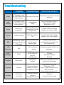
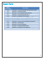
1
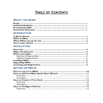
Dual-Vision™ XC
User Manual
90-21 144th Place, Jamaica, New York USA 11435
Phone: 800-227-2095
Fax: 718-297-0323
www.roscovision.com
Version 1.0
©2013 Rosco® Vision Systems, All Rights Reserved
Specifications and details are subject to change without prior notice.
Patent Pending
1
TABLE OF CONTENTS
For latest version of User Manual please visit www.roscovision.com
Safety Instructions ....................................................................................................3
Introduction ...............................................................................................................4
Package Contents .....................................................................................................5
Recorder ........................................................................................................................ 5
Accessories .................................................................................................................... 5
Package Contents .....................................................................................................6
Installation .................................................................................................................7
PDC (Power/Data Control) Module Installation ............................................................. 8
Mounting the Dual-Vision™ XC Recorder ....................................................................... 9
Mounting the Dual-Vision™ XC Recorder ..................................................................... 10
Installing External IR Module and Driver Event Button ................................................ 11
AUX Camera (Optional) ................................................................................................ 12
Technical Specifications ........................................................................................13
SD Card....................................................................................................................14
IMPORTANT! ............................................................................................................... 14
SD Card Formatting ...................................................................................................... 15
Operation .................................................................................................................16
Preparation to Start Video Recording .......................................................................... 16
Continuous and Event Recording ................................................................................. 17
Dual-Vision™ XC Player Program..........................................................................18
Configuring your PC to Enable Player Program ............................................................ 18
IMPORTANT! ............................................................................................................... 19
System Setup and Configuration ...........................................................................20
Parking Surveillance Setup ....................................................................................21
Player Screen ..........................................................................................................22
Video Playback Instructions ......................................................................................... 23
AVI File Conversion ...................................................................................................... 24
Interfacing with Google Maps ...................................................................................... 25
Additional Playback Functions and Pop-up Displays .................................................... 26
Setting Up and Analyzing G-SENSOR Data ..........................................................27
LCD Display .............................................................................................................28
Troubleshooting ......................................................................................................29
Spare Parts ..............................................................................................................30
Rosco Commercial Warranty .................................................................................31
2
Safety Instructions
To ensure proper operation please read this User Manual before
installation and operation. Failure to follow this safety notice may cause a
malfunction and will void the warranty.
IMPORTANT
DO NOT REMOVE THE SD CARD
WHILE DUAL-VISION™ XC
RECORDER IS POWERED
Depending on Configuration Settings in Dual-Vision™ XC
Player / DV-Pro® the Recorder may remain powered
even after the vehicle ignition has been turned off --Refer to “SD Card” Section on Page 13
CAUTION
THE FOLLOWING ACTIONS WILL VOID WARRANTY AND
MAY CAUSE AN ELECTRICAL SHORT CIRCUIT
DO NOT:
- Clean recorder with any liquids
- Insert foreign materials into the Dual-Vision™ XC device
- Attempt to disassemble, repair or modify the product
- Use cables, SD cards or fuses that are not provided by or recommended by Rosco®
NOTE
GPS
The windshield mounted Dual-Vision™ XC unit must have direct line-of-sight to the sky in order to
reliably acquire GPS satellite signals.
SD CARD
The SD card must be reformatted periodically. If the “EVENT” folder is full, new events may not be
properly marked or protected against over-writing.
3
Introduction
Rosco’s Dual-VisionTM XC allows recording of exterior/interior video and vehicle travel data.
Mounted on the windshield, Dual-VisionTM XC’s twin cameras capture wide-angle views of the
forward exterior field of vision and the driver/passenger compartment. Privacy concerns may be
addressed through several means, including disabling of interior audio recording.
Data is recorded in a continuous loop, with oldest video erased by more recent video. The
compact system can hold many hours of data before any over-writing takes place. An internal
GPS antenna enables capture of vehicle location, speed, and direction. Important “Events” such
as excessive G-Force and speeding are placed in special protected files along with video
segments identified by the driver as being important.
All the data is stored in proprietary files located on a removable SD card. Video, audio,
location information, and G-force data may ONLY be reviewed by accessing the contents of the
SD card using Rosco’s proprietary Player software on any Windows PC. The software is
provided at no additional cost to the end-user, and there are no follow-up fees for use or
updating of the Player by authorized users. Critical videos may be converted to standard mediaplayer formats for transmission to legal or administrative offices.
Security: Dual-VisionTM XC is a commercial grade product designed to be used in a variety of
applications. The optional Security Lock discourages unauthorized removal of the SD card.
Installation via hard-wire connection to a vehicle’s electrical system discourages tampering and
provides recording capability even after the engine has been shut off.
Optional DV-Pro® Fleet Management Software: Dual-Vision™ XC kits are complete with our
standard Dual-Vision™ XC Player software. For more advanced needs, Rosco has developed DVPro®, an exclusive fleet management software program for managing multi-vehicle video
recordings and data. This powerful software provides the ability to archive footage or to insert
descriptive tags highlighting video segments of interest. Post-route GPS data is easily accessed
to help evaluate location, routing, and speed.
The DV-Pro® software includes a comprehensive set of driver behavior reports. The program
enables export of data to Excel spreadsheets for further analysis and distribution of detailed reports
to management. There are no monthly fees or setup costs associated with DV-Pro®. Contact
Rosco Vision Systems or your authorized dealer for more information.
IMPORTANT
If you have a problem printing this document, please download and install the
latest version of Adobe Reader:
http://www.adobe.com/support/downloads/product.jsp?platform=windows&product=10
4
Package Contents
RECORDER
OR
RECORDER: Dual-Vision™ XC Recorder
RECORDER: Dual-Vision™ XC
with Security Lock and Adhesive Mounting Kit.
SD Card included with most models.
Recorder without Security Lock. SD
Card included with most models.
ACCESSORIES
WIRING: Power Wire: RED
PDC: Power/Data Control Module
Ignition Wire: YELLOW
With 3 AMP Mini-Fuses
5
Package Contents
ACCESSORIES
EXTERNAL
IR MODULE
EXTERNAL
IR POWER CABLE
DRIVER EVENT BUTTON
with CABLE
Lock Washer #8 & Machine Screw
Red Nylon Ring Terminal
Two Red Nylon Butt Connectors
DUAL-VISION™ XC
WINDSHIELD
MOUNTING BRACKET
without SECURITY
LOCK
Two Cable Raceways
Heat Shrink Tube
Four Screws:
#6 x ½” Self Drilling Type, Phillips Pan
Two for Mount Lock Housings
Two for PDC Module Mounting
DUAL-VISION™ XC CD:
Software
User Manual
Quick Start Guide
Label
6
Installation
This is the preferred installation for commercial and other fleet vehicles. The PDC Module provides
the power regulation and data control necessary for proper operation of the Dual-Vision™ XC
Recorder.
-
Each vehicle has its own system and features. Please refer to your vehicle’s manual for
details.
Turn the ignition key off while installing the cables and device.
Select a secure protected location for the PDC module.
Make sure to connect Ground wire first!
7
PDC (Power/Data Control) Module Installation
1. Prepare all the parts necessary for installation.
2. Find the location of the fuse box in the vehicle. Identify the
fuses for connection of the RED POWER wire and the
YELLOW IGNITION wire. Identify appropriate location for
installation of the PDC Module in the vehicle.
3. Identify approximate Dual-Vision™ XC Recorder location
on windshield. Confirm sufficient cable length available to
connect PDC to the Dual-Vision™ XC Recorder. Remove
the A-Pillar cover and insert the cable at the gap between
ceiling and windshield.
4. After determining that PDC location is appropriate, trim the
cable length as necessary, and make the following
connections:
a. Connect the BLACK WIRE (GROUND -) with ring
terminal to a chassis ground.
b. Connect the RED wire (POWER +) to a constant –
powered source which will remain live after the
ignition is turned OFF.
c. Connect the YELLOW wire (IGNITION) to an ACC
power source.
EXAMPLE:
Ground Wire Ring
Terminal connected to the
vehicle chassis ground
8
Mounting the Dual-Vision™ XC Recorder
1. Determine Dual-Vision™ XC Recorder location on windshield.
Typically the Recorder is mounted behind and slightly below the
mirror.
Make sure the interior-facing camera and the LCD display are
not obstructed by the mirror. Different vehicle/windshield
combinations allow many other acceptable mounting locations
(see alternate Dual-Vision™ XC location at left). The goal is
always to minimize forward-viewing obstruction while enabling
optimal recorded images. Dual-Vision™ XC Recorder should be
level both vertically and horizontally.
2. Clean the windshield glass with commercial glass cleaner. Using
the adhesive pad marked “temporary”, place Windshield
Mounting Bracket on windshield at the selected location. Slide
Dual-Vision™ XC Recorder into the bracket and connect
Recorder cable to the cable from the PDC Module.
3. Turn the vehicle ignition on, and observe LCD display on
Recorder to confirm proper electrical connection. (See Page 18
for details)
4. Allow Recorder to run for a few minutes. Turn the vehicle ignition
off and confirm the LCD display is off, indicating that no power is
going to the Recorder.
5. Remove SD card and review video to confirm GPS acquisition
and camera views. (See Pages 19 – 23 for Player instructions) If
acceptable, proceed to next step for permanent installation.
6. Once testing has confirmed proper location, remove the DualVision™ Recorder and Windshield Mounting Bracket. Using a
marker, note the position of the holes on the sides as shown in
left image.
7. Peel off the temporary adhesive pad and clean the windshield.
Break open the glass primer ampoule and apply a layer of 3M
Primer on the surfaces of both the Windshield Mounting Bracket
and the windshield. Let the primer dry for at least two minutes.
Attach the permanent adhesive pad to the Windshield Mounting
Bracket, and then carefully press the assembly onto the
windshield, holding it in place with pressure for about 30 seconds.
9
Mounting the Dual-Vision™ XC Recorder
IMPORTANT
Installation of permanent mounting should only be done when windshield is at room
temperature. Allow 2-4 hours for adhesive bond to cure properly before operating vehicle.
8. To permanently set the Recorder mounting position and the camera angle, insert screws into
the two bracket mounting holes using a screwdriver, as follows:
1. Remove the Recorder from windshield
mount, using care to avoid changing
the angle.
2. Remove the Recorder from windshield
mount, using care to avoid changing
the angle.
Two Screws:
#6 x ½” Self Drilling,
Philips Pan
3. With the camera angle now locked into
position by the screws, re-insert the
Recorder into the Windshield Mounting
Bracket and press the lock button to
secure the Recorder in the windshield.
Heat Shrinkable Tube
9. Connect Recorder cable to the PDC Module cable. For
most vehicles, this connection will be made within the
overhead space, and will be covered by the headliner.
For additional security, or for installations on very large
windshields, a heat shrinkable tube is provided for sealing
the connection point. Cover exposed cable with included
cable raceways as needed – cut raceways to size.
From Recorder
From PDC Module
10. Check all of your connections and confirm the following LCD
display status after parking surveillance mode is activated
(see Page 17 for details):
a. After ignition is turned off, a blinking LCD will indicate
parking surveillance is operational.
b. If LCD does not blink, surveillance mode is not active.
10
Installing External IR Module and Driver
Event Button
1. Clean the surface with commercial glass cleaner
before attaching the External IR Module. Please
make sure that the mounting direction of the IR
module is as indicated by the yellow label. For the
most effective lighting, make sure there are no
obstructions in front of the External IR module.
2. Connect the External IR Module cable to the PDC Module as shown.
3. Find the best location for the Driver Event Button.
Use caution in avoiding locations where the button
may be inadvertently pressed, such as by the
driver’s knee. Remove the adhesive film and
attach the button. Connect the Driver Event Button
plug to the PDC Module.
4. Secure all loose wires and components with cable
ties and reinstall vehicle panels.
External IR Module
5. Typical Dual-Vision™ XC completed installation.
11
AUX Camera (Optional)
Dual-Vision™ XC is capable of recording video from a third camera which may be connected to the
AUX Camera port on the PDC module. Rosco has a full range of interior and exterior cameras
available.
See your dealer, Rosco representative, or visit www.roscovision.com for further information.
Some typical AUX camera selections are shown here:
Rearview Camera
Bumper Camera
Side View Camera
License Plate Camera
Interior Dome Camera
Rear Hatch Camera
To enable AUX Camera option, an additional Rosco Camera, Extension Harness to proper
application length, and PDC power harness HAR6025 must be used. Please purchase separately
from Rosco Vision Systems.
Adaptor Cables for AUX Camera
PDC Module
12
Technical Specifications
PRODUCT SPECIFICATIONS
Built-in Cameras
Two 1.3 Megapixel CMOS Sensors
Camera Viewing Angle
Front 120° / Rear 170°
Focus
30cm to Infinite
Video Compression
H.264 / AVC Constant Bit Rate
Resolution
VGA (640X480)
Audio
1CH, Mono (in & out)
GPS
Built-in GPS module w/antenna
G-Sensor (X, Y, and Z)
Built-in 3D Acceleration Sensor
Volume
Configurable (0 Mute – 5)
Video Quality for Recording
Configurable (1 basic - 5 high)
Video Frame Rate
Configurable (0–15 frames/sec/camera)
Memory Card
SD Card
16GB up to 32GB
Operating Voltage Range
9Vdc ~ 30Vdc
Operating Temperature Range
-30C ~ +85C (-22F ~ +185F)
Storage Temperature Range
-40C ~ +85C (-40F ~ +185F)
Size
W 2.62” x L 3.95” x T 1.12”
Weight
6 oz. unit only, 8.7 oz. with locks
Current Consumption at 12v DC
Maximum ~500mA
Operation ~300mA
Standby
~100mA
External IR module current
On mode
~100mA (standalone)
Standard Compliance
FCC
CERTIFIED Part 15 Subpart B (Class A)
EMC
ANSI C63.4-2009
CE
CERTIFIED
13
SD Card
IMPORTANT
•
•
Remember to ALWAYS disconnect POWER prior to removal of SD Card from
Dual-Vision™ XC Recorder.
When parking surveillance mode is OFF, turn ignition off. It is safe to remove the SD card
after the Recorder’s LCD display turns off.
If parking surveillance mode is ON, turn ignition off and wait for few seconds until the LCD
display begins blinking. Then press and hold the Event Release Button for 3 seconds. The
LCD will turn off following a chime. It is safe to remove the SD card after the display turns
off.
LCD ON
EVENT
RELEASE
BUTTON
LCD OFF
Do Not Use SD Card for any other purpose. Using this SD Card for any other purpose or removing the
card while the Recorder is powered may cause a fatal error on the SD Card. You will lose important data
if SD card is removed when powered.
Recommended: Create a folder on PC and copy Dual-Vision™ XC files from SD Card.
At least once per month, format the SD Card using the included “SDFormatterv3.0” program to prevent
SD Card errors from occurring over a long period of time. Note that upon formatting the SD Card, all
existing operating and data files will be deleted. Be sure to perform a backup of any important video files
and configuration prior to reformatting. After formatting, you may insert the SD card into Dual-Vision™
XC. The Recorder will automatically write the Configuration file to the SD card. The “Player” program
does not automatically re-install onto the SD Card. If desired, it may be added manually by copying and
pasting from another location. A new Data folder will be created on the reformatted SD Card and new
Data files will be created as driving resumes.
Consult Rosco or your Authorized Reseller for SD Card compatibility. Not all SD Cards work with DualVisionTM XC unit. The following is a list of approved SD Cards which may be purchased from Rosco. This
list may be periodically updated without notice.
MEMORY
SD CARD
16GB
San Disk Ultra SDHC Class 4
Transcend SDHC Class 4
Transcend SDHC Class 6
Transcend SDHC Class 10
32GB
Transcend SDHC Class 6
Transcend SDHC Class 10
In case your computer does not support the SDHC Memory Card Standard, use a separate SDHC
USB 2.0 reader (SD to USB adapter).
14
SD Card Formatting
1. Open “SDFormatter V3.0.0.0” Program.
Select the SD CARD drive. (SD Card will be
automatically recognized if SD Card is
inserted.)
2. Click “Option” and enable “Format size
adjustment” to “ON”.
to
3. Click “Format” button to format the SD card.
4. Click “OK” to continue with quick format and
follow the instructions.
5. Do not remove the SD card. Click “OK” again
to continue.
6. Driver Format is complete. Click “OK” to
close. Remove SD card and re-insert into
Dual-Vision™ XC Recorder.
15
Operation
1. SD Card Port
7. LCD Display
2. Event Release Button*
8. Rear Camera (Interior View)
3. Driver Event Button
9. Infrared Illuminators
4. Windshield Mount Push Lock
10. Microphone
5. Speaker
11. Windshield Mount with built-in GPS Module
6. SD Card Security Lock
12. Front Camera (Exterior View)
* Event Release Button has two functions. When enabled in the Configuration menu within the Player program, it
would allow drivers to remove protection on Event files. This permission, however, is disabled in most applications.
The second function is for powering down the Recorder as follows:
For SD Card removal when Parking Surveillance is enabled, turn ignition off and wait for few
seconds until the LCD display begins blinking. Then press and hold the Event Release Button for 3
seconds. The LCD will turn off following a chime, indicating that Power is OFF. It is safe to remove
the SD card after the display turns off.
Preparation to Start Video Recording
•
With new or freshly formatted SD Card inserted into Recorder, turn ignition on. “Init” will
appear on the LCD display indicating that the Recorder is initializing. Approximately one
minute after powering on, the unit should complete initializing and a “ding-dong” chime will
sound. Although GPS still may not be active, recording begins.
•
LCD Display will indicate the number of G-force or Driver-Button Events recorded since last
reset. This alphanumerical code (ex. E001) will remain displayed for 10 seconds. Next, a
similar display (ex. S002) will indicate the number of times the speed limit was exceeded.
•
The LCD Display will show four dashes (----), indicating that GPS satellite signal is being
acquired. This may take up to 5 minutes on initial startup, quicker on subsequent vehicle
starts. When “GPS“ icon is lit, GPS location data is now being embedded into the recording
along with vehicle speed and direction.
NOTE: When vehicle is in motion, LCD displays vehicle speed. When vehicle is stopped, LCD displays local time.
16
Continuous and Event Recording
•
When the ignition is OFF, Dual-Vision™ XC Recorder remains powered for an additional 510 seconds to finish recording. If Parking Surveillance is ON, LCD Display will blink slowly
and the recording will be continued.
EVENT
RELEASE
BUTTON
LCD ON
LCD OFF
•
Dual-Vision™ XC creates proprietary files (identified as “.asd” files) which contain video, audio,
and tracking data. Proprietary .asd files will only play on Dual-Vision™ XC Player or DV-Pro®.
•
Event Recording - When preconfigured speed or G-sensor values are exceeded, or when
Driver Event Button is pressed, an “EVENT” is created. The .asd file associated with that Event
is marked and protected against overwriting.
•
Continuously recorded .asd files are NOT protected against overwriting. When the capacity of
the SD Card has been reached, the oldest non-Event files are overwritten. “Event” data files, as
noted above, are NOT overwritten.
•
Video files may be password protected at the manager’s option. In the Configuration menu,
enter and confirm password, then place a check mark on “use password”. Make certain to
record the password in a safe place.
17
Dual-Vision™ XC Player Program
Configuring your PC to Enable Player Program
Certain PC configurations cause a pop-up to appear when trying to open the Dual-Vision XC
Player Program. The pop-up states “Admin rights required on this computer”. Follow this
procedure upon first installing the program, in order to be able to open the Player Program without
getting the pop-up message.
NOTE: Player is compatible with most PC operating systems (Vista, Windows XP, Windows 7). It is not compatible with MAC.
1. Insert the SD Card into a PC or use SD Card
Reader to connect to PC.
2. Select SD Card drive (Removable Disk).
3. Double-click the “PLAYER” folder.
4. Double-click the “Player.exe” to execute the
program.
18
Dual-Vision™ XC Player Program
IMPORTANT
If a warning appears and requires “administrator rights” on your PC, please perform the actions
shown below.
1. Right click on “Player.exe” file – this window will open.
Click on “Compatibility” tab.
2. In the “Compatibility” tab, place a check mark on “Run this
program in Compatibility mode for:” Choose “Windows 7”
or whichever Operating System you computer is using.
3. In “Privilege Level” place a check mark on “Run this
program as an administrator.”
4. Then click to “Apply” and the click “OK”
5. Open the Player program again. It should open without a
“pop-up” warning.
19
System Setup and Configuration
Configure your Dual-VisionTM XC Recorder prior to installation. (Player v1.1.0.1 or later)
Run “player.exe” program located on your SD card, User Manual CD or Desktop (if copied to your PC)
Click on the System Setup configuration icon (
) located at the lower right corner of the player. The
following window will then appear.
CONFIGURATION ITEM
DESCRIPTION
Video Quality
Video Rate – Frames /
Second
Video Format
Recommendation: 1-Normal is satisfactory for most applications
Recommendation: 5 Frames / Second / Camera. If you are using only 2 internal
cameras (C1 & C2), set AUX camera OFF
For AUX camera (external): Select NTSC for US customer
Audio Recording
Turn audio ON or OFF
Password Setting
Video data files may be password protected at the manager’s option
Time Zone Setting
Sets the correct time zone and Daylight Savings Time where applicable
Unit of Speed
MPH, KPH, or KNOTS
Vehicle Number
Manager generated ID – this will appear on the SD card recordings
Speed Limit
Do not leave blank. Enter a high value if notification is not desired
Speed Tag / Event
Options to choose unprotected “Tag Only” or protected Tag + Event
Event Replace Selection
Replace oldest Event with newest Event when SD Card Events “FULL”
Brightness of LCD
Brightness setting from 0 – 5
Disable Erase Button
Prevents drivers from activating the Event Release Button (see Page 10)
Speaker Volume
Adjusts chime volume from 0 – 5
G-Sensor Sensitivity
Sets the X, Y and Z sensitivity in 0.1G increments up to 4.0G (see Page 27)
Remote Cam. Option
Select the external AUX camera type
Parking Setup
Configure parking surveillance mode
20
Parking Surveillance Setup
CONFIGURATION ITEM
Timer for parking
DESCRIPTION
OFF or ON 5 Min, 10 Min, 30 Min, 1 Hour up to 24 Hours
Video Quality
Recommendation: 1-Normal is satisfactory for most applications
Frame Rate
Recommendation: 1 or 2 frames / second / camera
Audio Recording
Turn audio ON or OFF for both cameras
Configure sensitivity of G-Sensor (sets for each X, Y, Z axis by 0.1 Gravity Sensor
Level up to 4.0G)
G-Sensor Sensitivity
*NOTE: Parking Surveillance settings are independent from the values selected for normal driving
mode Configuration.
21
Player Screen
A
B
R
E
S
D
C
G
H
I
J
K
F
L
M
N
NAME
DESCRIPTION
A
Forward Camera
Displays exterior video recorded through the windshield
O
P
Q
B
Interior Camera
Displays interior video, typically driver and passengers
C
Vehicle Speed
Displays the speed of your vehicle
D
Vehicle Location
Displays map coordinates (latitude and longitude)
E
Direction of Travel
Displays vehicle direction
F
G-Force Analyzer
3-axis graphic displays vehicle motion and any impact detected by the G-Sensor
G
Previous File
Move to the previous file
H
Previous Frame
Move to the previous frame
I
Next Frame
Move to the next frame
J
Next File
Move to the next file
K
Volume Control
Move slider to adjust volume of playback audio
L
Playback Speed
Adjusts from slow to fast forward. Must be set at center (normal speed) to hear audio
M
File Open
Open a video file
N
AVI Converter
Convert the file into an AVI format
O
Map
Show the vehicle location on the map
P
Configuration
Setup configuration
Q
Exit
Close the Player program
R
Aux Camera Button
Displays video from additional camera (optional)
S
Reverse Button
Reverse Aux camera video image
22
Video Playback Instructions
1. To playback video, select the “asd” icon ( ), if no asd files appear, click “change directory”
button.
2. Select “Removable Disk” where the recorded data is stored and choose “data” folder.
3. Select and double click asd file to play video.
Displays the type
of recorded
events
(G-SENSOR,
BUTTON,
SPEED)
File name of
recorded video
Date and time
when the video
was recorded
*NOTE: Click menu bar to sort by file name, record time or event type
EVENT TYPE
DESCRIPTION
SPEED Event
Indicates when the vehicle exceeds pre-configured speed limit
BUTTON Event
Indicates activation of Driver Event Button
G-SENSOR Event
Indicates when vehicle experienced sudden acceleration, deceleration or rapid
side-to-side movement (see Page 27)
PARKING Event
Indicates Parking Mode Events when vehicle is parked
23
AVI File Conversion
To convert a portion of the recorded data into an .avi file for viewing on programs such as Windows
Media Player. Use of this feature enables sharing of the recorded data with any computer via email
or file transfer.
1. In Player, view the file containing the
video of special interest. Pause the
Player at the point where conversion is
desired. Click the AVI button (
), select
target directory, and make the desired
selections (see below). Note: The .avi
files cannot be stored to media such as
SD Card or USB memory stick, but only
to a hard disk. Click on Start and
conversion will take place.
2. The conversion progress appears as
follows:
3. The converter will create two files,
one of forward-facing video and one
of the interiors video, and will place
them in the desired PC directory.
24
Interfacing with Google Maps
Dual-Vision™ XC records GPS data to enable historical review of vehicle location and route. The
map coordinates can be synchronized with Google Maps® by clicking the Map icon ( ) on the
lower right corner. To use this function, the PC must have an internet connection.
25
Additional Playback Functions and Pop-up
Displays
Double-clicking the display window will temporarily enlarge the recorded image in that window.
Double-click again to return to original size. Use the mouse to move the screens within the
desktop window.
FRONT CAMERA
REAR CAMERA
AUX CAMERA SCREEN
26
Setting Up and Analyzing G-SENSOR Data
The G-Force sensor detects changes in directional forces affecting the vehicle. The Dual-Vision™
XC Player displays G-force data in a graphical format, and creates Events when those forces
exceed supervisor-set values. One may interpret the data as follows:
ACCELERATION
REAR COLLISION
DECELERATION
E X A M P L E S O N L Y
VEHICLE STOPPED
FRONTAL COLLISION
KEY
X-AXIS : LEFT / RIGHT MOTION
Y-AXIS : FRONT / BACK MOTION
Z-AXIS : UP / DOWN MOTION
LEFT / RIGHT TURN
Vehicle Type
X, Y, Z Axes
School Bus
Shuttle Bus
Coach Bus
Truck (Highway)
Truck (Local)
Sedan
1.0, 1.0, 2.0
1.0, 1.0, 2.0
1.0, 1.0, 2.0
1.0, 1.0, 2.0
1.2, 1.2, 2.5
0.8, 0.6, 1.8
Suggested Configuration Settings
Setup G-Force Sensor
Note that X & Y axes are 0 when vehicle is stationary. The Z- Axis is typically at +1 when
vehicle is stationary, due to the effect of the earth’s gravitational force. Using the slidebars, adjust the values for each axis. This is a trial-and-error effort, since different types of
vehicles will react differently under various road conditions. The values represent a range (+
or -) around G=0. The values for the Z-Axis must be set above 1, so that it does not record
Events while the vehicle is not moving. Under normal driving conditions for an automobile,
settings of X= .8G, Y= .6G, Z= 1.8G are recommended as being sufficient to identify driverbehavior issues while being high enough to avoid most unnecessary Event-marking caused by
potholes or normal braking. Please see the above chart for suggested settings appropriate for a
variety of commercial vehicles.
27
LCD Display
DISPLAY
DESCRIPTION
Display Time of Day when vehicle is stationary. Displays
Speed when vehicle is moving.
Event log almost full – counts down from 5 to FULL
Displays number of total G-Force and Driver Button Events
since last reset in “Configuration” Menu
Displays number of total Speed Events and Tsga since last
reset in “Configuration” Menu
When lit, indicates AUX camera video is recording
When lit, indicates interior view camera is recording
When lit, indicates forward view camera is recording
When lit, GPS acquisition is active
Designated speed measurement unit
When lit, indicates Event file is being flagged and protected
28
Troubleshooting
Problem
Possible Cause
Corrective Action
Power
LCD display is dark.
No chime heard upon
starting vehicle.
No power to Recorder
Check the power cable connection
and fuses
LCD
Display
LCD display is faint,
but chime heard upon
starting vehicle.
Low brightness
setting
Open Configuration screen in
Player program. Adjust
“Brightness of LCD”.
Event
Event icon is
constantly lit.
Constant Events and
chimes due to bumps
and potholes
Increase G-Sensor settings
based on your vehicle needs
Speed
Constant chiming
Speed limit set too
low
Increase Speed limit settings
based on your vehicle needs
GPS
GPS icon remains unlit
while driving, vehicle
speed not indicated on
LCD display
GPS antenna is not
able to acquire
satellite signal
Relocate Recorder and
mounting base to position with
line-of-sight to sky
LCD
Message
ErrX
Error notices on
display
LCD
Message
SD_E
SD Card error
No SD Card, SD
Card not
reading/writing
Remove and properly insert
SD card
Reformat or replace
SD Card
Playback
Blurry video
Camera/lens
problem
Make sure Camera/lens is clean
and clear of obstructions
Contact your dealer or Rosco for
Assistance
Playback
No audio
Improper software
settings in Player or
Configuration screens
Configuration - set Audio
Recording to “ON”.
Player – adjust Volume Control
slider as desired.
Check speaker settings on PC.
Speaker
No chime or
loud chime
Improper software
setting in
Configuration screen
Adjust the
Speaker Volume setting
29
Spare Parts
Rosco
Part Number
Description
DV212
Dual-Vision™ XC 16GB SD card with DVXC Player & SDFormatter
DV213
Dual-Vision™ XC External IR Module
DV216
Dual-Vision™ XC Security Mount Bracket with Keys
DV217
Dual-Vision™ XC Key Set, 2pcs, Key Code "X"
DV226
Dual-Vision™ XC Adhesive Pads plus Primer
DV234
Dual-Vision™ XC 32GB SD card with DVXC Player & SDFormatter
DV243
Dual-Vision™ XC Power-Data-Control (PDC) Module Kit
DV226
Dual-Vision™ XC Adhesive Pads plus Primer
DV235
Dual-Vision™ XC DV231 Full KIT except DV291 Recorder unit
DV240
Dual-Vision™ XC Hardware Kit
DV241
Dual-Vision™ XC Driver Event Button
DV242
Dual-Vision™ XC Windshield Mount Bracket
DV244
Dual-Vision™ XC External IR Power Cable (8 ft.)
DV291
Dual-Vision™ XC Dual Recorder with SD Card Security Lock
30
Rosco Commercial Warranty
We warrant that all ROSCO mirror, camera, sun visor, and electronic vision products are free
from defects in workmanship and materials for a period of ONE (1) YEAR from the date of
receipt of the product. During the warranty period, we agree to provide a replacement for (or at our
option, repair) the ROSCO product and/or any one or more component parts of a ROSCO
product which malfunctions under normal use and service.
Upon discovering a defect, the customer must contact ROSCO for a return authorization
and then must return the product, and/or component part, together with proof of date of receipt
of the product, to ROSCO INC. 144-31 91st Ave. Jamaica, New York 11435. The customer and
not ROSCO will be responsible for the payment of all removal, installation and transportation
charges for return of defective products or components to ROSCO. Transportation charges for
such return must be prepaid. The repaired or replaced equipment will be returned to the customer
with transportation charges prepaid by ROSCO. Replacement (or repaired) products and/or
component parts are warranted only for the unexpired term of the original warranty.
This warranty does not cover defects caused by neglect, misuse, incorrect application,
incorrect installation, water damage, vehicle wash facilities, alteration or repair in any manner
outside ROSCO’s factory. Damage caused by the return shipment due to inadequate packaging
or mishandling will not be covered. If the alleged defect is due to any of these causes, the
customer will be advised of the findings and asked what action is to be taken. If ROSCO is
requested to repair the product, a repair charge estimate will be prepared and the customer’s
written permission (purchase order, repair, etc.) will be necessary to proceed with the repair of
the product and/or component part. Transportation charges for such returns will be the
responsibility of the customer.
This warranty may not be expanded by oral representation, written sales information, and
drawings or otherwise. Repair or replacement is the exclusive remedy for defective
products under this warranty. This warranty is expressly in lieu of all other warranties,
including any implied warranty of merchantability or any implied warranty of fitness for a
particular purpose on any ROSCO product. ROSCO shall not be liable for any consequential or
incidental damages for breach of any express or implied warranty on any ROSCO product.
31