1
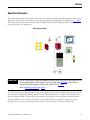
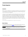
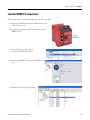
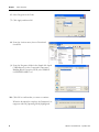
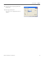
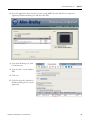
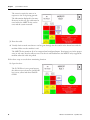
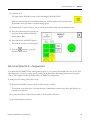
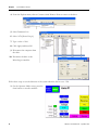
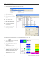
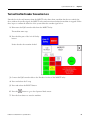
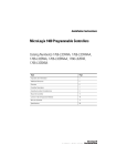
Quick Start
Simple Safety with Guardmaster MSR57P Speed
Monitoring Safety Relay
Catalog Number 440R-S845AER-NNL
Important User Information
Solid-state equipment has operational characteristics differing from those of electromechanical equipment. Safety
Guidelines for the Application, Installation and Maintenance of Solid State Controls (publication SGI-1.1 available from
your local Rockwell Automation sales office or online at http://www.rockwellautomation.com/literature/) describes some
important differences between solid-state equipment and hard-wired electromechanical devices. Because of this difference,
and also because of the wide variety of uses for solid-state equipment, all persons responsible for applying this equipment
must satisfy themselves that each intended application of this equipment is acceptable.
In no event will Rockwell Automation, Inc. be responsible or liable for indirect or consequential damages resulting from
the use or application of this equipment.
The examples and diagrams in this manual are included solely for illustrative purposes. Because of the many variables and
requirements associated with any particular installation, Rockwell Automation, Inc. cannot assume responsibility or
liability for actual use based on the examples and diagrams.
No patent liability is assumed by Rockwell Automation, Inc. with respect to use of information, circuits, equipment, or
software described in this manual.
Reproduction of the contents of this manual, in whole or in part, without written permission of Rockwell Automation,
Inc., is prohibited.
Throughout this manual, when necessary, we use notes to make you aware of safety considerations.
WARNING: Identifies information about practices or circumstances that can cause an explosion in a hazardous
environment, which may lead to personal injury or death, property damage, or economic loss.
ATTENTION: Identifies information about practices or circumstances that can lead to personal injury or death,
property damage, or economic loss. Attentions help you identify a hazard, avoid a hazard, and recognize the
consequence
SHOCK HAZARD: Labels may be on or inside the equipment, for example, a drive or motor, to alert people that
dangerous voltage may be present.
BURN HAZARD: Labels may be on or inside the equipment, for example, a drive or motor, to alert people that
surfaces may reach dangerous temperatures.
IMPORTANT
Identifies information that is critical for successful application and understanding of the product.
Allen-Bradley, Rockwell Software, Rockwell Automation, DriveExecutive, DriveExplorer, MicroLogix, Guardmaster, PowerFlex, PanelView, Lifeline, and TechConnect are trademarks of Rockwell Automation, Inc.
Trademarks not belonging to Rockwell Automation are property of their respective companies.
Where to Start
Connected Components Building Block Outline
Follow the path below to complete your connected components building block.
Connected Components
Building Blocks, publication
CC-QS001
Chapter 1 Product
Integration
Chapter 2 System
Validation and Test
3Publication CC-QS022B-EN-P - September 2010
3
Where to Start
4
Publication CC-QS022B-EN-P - September 2010
Table of Contents
Preface
About This Publication . . . . . . . . . . . . . . . . . . . . . . . . . . . . . . . . . . . . . . 7
Conventions . . . . . . . . . . . . . . . . . . . . . . . . . . . . . . . . . . . . . . . . . . . . . . . 8
Additional Resources . . . . . . . . . . . . . . . . . . . . . . . . . . . . . . . . . . . . . . . . 9
Chapter 1
Product Integration
Introduction . . . . . . . . . . . . . . . . . . . . . . . . . . . . . . . . . . . . . . . . . . . . . . 11
Before You Begin. . . . . . . . . . . . . . . . . . . . . . . . . . . . . . . . . . . . . . . . . . 11
What You Need . . . . . . . . . . . . . . . . . . . . . . . . . . . . . . . . . . . . . . . . . . . 12
Follow These Steps . . . . . . . . . . . . . . . . . . . . . . . . . . . . . . . . . . . . . . . . 12
Modify the PowerFlex 40P Configuration Parameters. . . . . . . . . . . . . 13
Load the MSR57P Configuration . . . . . . . . . . . . . . . . . . . . . . . . . . . . . 15
Chapter 2
System Validation and Test
5Publication CC-QS022B-EN-P - September 2010
Introduction . . . . . . . . . . . . . . . . . . . . . . . . . . . . . . . . . . . . . . . . . . . . . . 19
Before You Begin. . . . . . . . . . . . . . . . . . . . . . . . . . . . . . . . . . . . . . . . . . 19
What You Need . . . . . . . . . . . . . . . . . . . . . . . . . . . . . . . . . . . . . . . . . . . 20
Follow These Steps . . . . . . . . . . . . . . . . . . . . . . . . . . . . . . . . . . . . . . . . 20
Configure and Validate MicroLogix Communication to
PowerFlex 40P Drive . . . . . . . . . . . . . . . . . . . . . . . . . . . . . . . . . . . . . . . 21
Configure and Validate Communications Between the PanelView
Component Terminal and MicroLogix Controller . . . . . . . . . . . . . . . . 22
Modify the Controller IP Address . . . . . . . . . . . . . . . . . . . . . . . . . 22
Review the Network Overview Screen. . . . . . . . . . . . . . . . . . . . . . 24
Review the Program Mode Screen . . . . . . . . . . . . . . . . . . . . . . . . . 25
Test and Confirm the E-stop Safety Function . . . . . . . . . . . . . . . . . . . 27
Test and Confirm the Cable Pull Switch and Door Monitoring
Safety Functions . . . . . . . . . . . . . . . . . . . . . . . . . . . . . . . . . . . . . . . . . . . 29
Test and Confirm the Light Curtain Safety Function. . . . . . . . . . . . . . 32
Test and Confirm the Maximum Speed Safety Function. . . . . . . . . . . 33
Test and Confirm the Safe Limited Speed Safety Function . . . . . . . . . 35
Normal Operation . . . . . . . . . . . . . . . . . . . . . . . . . . . . . . . . . . . . . . 35
Safe Limited Speed (SLS) – Overspeed Error . . . . . . . . . . . . . . . . 37
Test and Confirm Encoder Connection Loss. . . . . . . . . . . . . . . . . . . . 41
Parameter Backup and Restore (PB&R) . . . . . . . . . . . . . . . . . . . . . . . . 42
5
Table of Contents
6
Publication CC-QS022B-EN-P - September 2010
Preface
About This Publication
This Quick Start illustrates an example of a retrofit to an existing PowerFlex 40P drive-based position control
application, based on the Position Control Connected Components Building Block, publication CC-QS003.
The retrofit described in this Quick Start adds the MSR57P Speed Monitoring Safety Relay and a Lifeline4
cable pull switch to the application.
Safety System Diagram
IMPORTANT
Use this Simple Safety Connected Components Building Block Quick Start in conjunction with the
Connected Components Building Blocks Quick Start, publication CC-QS001 and the Position
Control Connected Components Building Block, publication CC-QS003.
Refer to Additional Resources on page 9.
To assist in the design and installation of your system, application files and other information are provided on
the Connected Components Building Blocks Overview DVD, publication CC-QR001. The DVD provides
bills of materials (BOM), CAD drawings for panel layout and wiring, control programs, Human Machine
Interface (HMI) screens, and more. With these tools and the built-in best-practices design, the system
designer is free to focus on the design of their machine control and not on design overhead tasks.
7Publication CC-QS022B-EN-P - September 2010
7
Preface
Read these sections carefully before beginning work in each chapter. The beginning of each chapter contains
the following information:
• Before You Begin - This section lists the steps that must be completed and decisions that must be
made before starting that chapter.
• What You Need - This section lists the tools that are required to complete the steps in the current
chapter. This includes, but is not limited to, hardware and software.
• Follow These Steps - This illustrates the steps in the current chapter and identifies which steps are
required to complete the examples.
Conventions
Convention
8
Meaning
Example
Check or uncheck
To activate or deactivate a checkbox.
Check Disable Keying.
Click
Click the left mouse button once while the cursor is positioned on
object or selection to initiate an action.
Click Browse.
Double-click
Click the left mouse button twice in quick succession while the cursor
is positioned on object or selection to initiate an action.
Double-click the application icon.
Expand
Click the + to the left of a given item /folder to show its contents.
Expand 1768 Bus under I/O Configuration.
Right-click
Click the right mouse button once while the cursor is positioned on
object or selection.
Right-click the 1768 Bus icon.
Select
Using the mouse to highlight a specific option.
Select the New Module folder.
Press
Pressing a specific key on the keyboard or button on a touchscreen.
Press Enter.
>
Use this symbol to indicate the sub-menu name.
Choose File>Menu>Options.
‘Project’
Refers to the application on both the controller side and the PanelView component side.
Publication CC-QS022B-EN-P - September 2010
Preface
Additional Resources
Resource
Description
Connected Components Building Blocks Quick Start,
publication CC-QS001
Provides information on how to select products and gain access to panel and
wiring information
Connected Components Building Blocks Overview CD,
publication CC-QR001
Provides files for the Connected Components Building Blocks
Position Control Connected Components Building
Block Quick Start, publication CC-QS003
Provides information installing and setting up the PowerFlex 40P drive
parameters with the pre-configured RSLogix 500 program that controls you base
system including application tips, as well as implementing the drive parameter
backup and restore functionality
MicroLogix 1100 Controller User Manual, publication
1763-UM001
Provides information on using the MicroLogix 1100 Programmable Controller
1762-IQ16 DC Input Module Installation Instructions,
publication 1762-IN010
Provides information on installing and using the 1762-IQ16 DC input module
PanelView Component HMI Terminals Installation
Instructions, publication 2711C-IN001
Provides information on installing PanelView Component HMI terminals
PanelView Component HMI Terminals User Manual,
publication 2711C-UM001
Provides information on using PanelView Component HMI terminals
2000 Ethernet Unmanaged Switch Installation
Instructions, publication 1783-IN001
Provides information on installing and using the 2000 Ethernet Unmanaged
Switch
PowerFlex 40P Quick Start, publication 22D-QS001
Provides information on installing and using the PowerFlex 40P drive
PowerFlex 40P User Manual, publication 22D-UM001
Provides information on using the PowerFlex 40P drive
MSR57P Installation Instructions, publication
440R-IN016
Provides information on installing the MSR 57P relay
MSR57P User Manual, publication 440R-UM004
Provides information on installing, programming, and operating the MSR 57P
relay
1203-USB USB Converter User Manual, publication
DRIVES-UM001
Provides information on using the 1203 USB converter
Point of Operation Control Safety Light Curtains
Installation Instructions, publication 75035-103-01(A)
Provides information on installing and using the 440L GuardShield Light Curtain
http://www.ab.com
Provides access to the Allen-Bradley website
http://www.rockwellautomation.com/knowledgebase
Provides access to self-service support
http://www.rockwellautomation.com/components/
connected/blocks.html
Provides access to the Connected Components website
Publication CC-QS022B-EN-P - September 2010
9
Preface
Notes:
10
Publication CC-QS022B-EN-P - September 2010
Chapter
1
Product Integration
Introduction
While it is common for an MSR57P relay to be included in the initial design of a system, in the field, the relay
is often integrated as a safety upgrade to an existing system as a retrofit. This Simple Safe Speed Connected
Component Building Block has been designed with the MSR57P relay as a retrofit to the existing Position
Control Connected Components Building Block.
As with any retrofit, as much as possible of the previously existing system is kept as intact. However, some
new hardware is required. The MSR57P relay and a TLS3-GD2 guardlocking switch are added to permit
authorized access when the machine is at its Safe Limited Speed. In addition, a Lifeline 4 cable pull safety
switch replaces the Emergency stop button of the Position Control Building Block, adding cable pull
capability to the E-stop function. Changes to the existing wiring are re-routings to integrate the MSR57P
relay into the system. Most input wiring to the MicroLogix remains intact with the new, safety-related
connections going, instead, to an added 1762-IQ16 DC input module. The existing MicroLogix controller
program logic is unchanged. MSR57P relay logic is added for the purpose of driving a new MSR57P-related
PanelView screen.
For practical purposes, this Building Block involves a single axis in the velocity mode.
Before You Begin
This Building Block presumes that you have the Position Control Connected Components Building Block
system up and running. Review publication CC-QS003 to verify installation and operation.
IMPORTANT
A safety risk assessment must be completed to make sure that all tasks and hazards are
considered and to confirm that the example circuit provides adequate risk reduction for your
specific application.
11Publication CC-QS022B-EN-P - September 2010
11
Chapter 1
Product Integration
What You Need
• MSR57P Speed Monitoring Safety Relay
• PowerFlex 40P drive
• Laptop computer
• DriveExplorer or DriveExplorer Lite software installed
• 1203 USB Converter
• USB cable to connect the converter to the laptop cable
• 22-HIM-H10 cable for connecting to the RJ45 port on the PowerFlex 40P drive
• 20-HIM-H10 cable for connecting to the DPI port on the MSR57P relay
• Simple Safe Speed MSR57.csf file from Connected Components Building Blocks OverView DVD,
publication CC-QR001
Modify the PowerFlex 40P Drive Configuration
PowerFlex 40P
Drive
1203-USB
Converter
Laptop
Computer
USB Cable
22-HIM-H10 Cable
Follow These Steps
Follow these steps to modify your PowerFlex 40P configuration to work with the MSR57P relay.
Start
Modify the PowerFlex 40P
Configuration Parameters on
page 13
Load the MSR57P Configuration
on page 15
12
Publication CC-QS022B-EN-P - September 2010
Product Integration
Chapter 1
Modify the PowerFlex 40P Configuration Parameters
Two parameters in the SimplePosition configuration file must be modified to implement the Safe Limited
Speed function of the MSR57P relay. These changes have no effect on the previous Speed or Position
functions. They operate exactly as before.
Follow these steps to make the necessary modifications.
1. Disconnect the RJ45 cable from the drive to the controller by removing the RJ45 plug at the drive.
2. Connect the 22-HIM-H10 cable to the 1203 USB converter and connect its RJ45 plug to the RJ45 port
on the drive.
3. Launch DriveExplorer software.
4. From the Explore menu, choose
Configure Communication.
5. Click Serial.
6. Select your Comm Port.
7. Select a Baud rate of 11500.
8. Click OK.
9. From the Explore menu, choose
Connect >Serial Point-to-Point.
Once you are connected the PowerFlex drive
screen appears.
Publication CC-QS022B-EN-P - September 2010
13
Chapter 1
Product Integration
10. Select Parameter List.
11. Double-click P53 [Digital In3 Sel].
12. Select Preset Freq.
13. Click Apply and then OK.
14. Double-click P74 [Preset Freq 4].
15. Type 1.00 as the Limited Safe Speed value.
16. Click Apply and then OK.
17. Disconnect the 22-HIM-H10 cable from both the
drive and the 1203 USB converter.
18. Reconnect the RJ45 plug on the cable from the
controller to the drive.
19. Leave DriveExplorer software running, as it will be used to load the MSR57P Simple Safe Speed
configuration.
14
Publication CC-QS022B-EN-P - September 2010
Product Integration
Chapter 1
Load the MSR57P Configuration
Follow these steps to load the configuration for the safety relay.
1. Plug the 20-HIM-10 PowerFlex HIM cable into the
1203 USB converter.
2. Plug the other end into the DPI receptacle on the
MSR57P relay.
DPI
Receptacle
3. From the Explore menu, choose
Connect>Serial Point-to-Point..
4. On the main MSR57P screen, click Parameter
List.
5. Double-click P6 [Operating Mode].
Publication CC-QS022B-EN-P - September 2010
15
Chapter 1
Product Integration
6. Select Program as the Value.
7. Click Apply and then OK.
8. From the Actions menu, choose Download
Saved File.
9. From the Programs folder in the Simple Safe Speed
CCBB directory in the Connected Components
Building Blocks Overview DVD, select SIMPLE
SAFESPEED MSR57.csf.
10. Click OK to confirm that you want to continue.
When the download is complete, the Parameter List
reappears with P6 [Operating Mode] highlighted.
16
Publication CC-QS022B-EN-P - September 2010
Product Integration
Chapter 1
11. Select Run from the Operating Mode Value
pull-down list.
12. Click Apply and then OK.
The system is now configured and ready for
validation.
Publication CC-QS022B-EN-P - September 2010
17
Chapter 1
Product Integration
Notes:
18
Publication CC-QS022B-EN-P - September 2010
Chapter
2
System Validation and Test
Introduction
In this chapter you confirm that the PanelView terminal, MicroLogix controller, MSR57P relay, and
PowerFlex 40P drive work together as intended.
You also test to confirm the proper operation of the safety system. A risk assessment is the first step and the
basis of all safety systems. Risk assessment is beyond the intended scope of this Building Block.
IMPORTANT
This Building Block assumes you have performed a risk assessment on the machine and that the
safety devices selected for use and the way they are integrated is proper and satisfies the risk
reduction requirements identified in the risk assessment.
Before You Begin
• Verify that the system is connected as shown in the Simple Safe Speed with the MSR57P CAD wiring
diagram.
• Verify that all system components have power applied to them.
• Review the Connected Components Building Blocks Quick Start, publication CC-QS001. Make sure
that all the steps, outlined in Chapter 3 Controller and HMI Integration, have been completed.
• Double-check to be sure that all the steps, outlined in Chapter 1 of this document, have been
completed.
19Publication CC-QS022B-EN-P - September 2010
19
Chapter 2
System Validation and Test
What You Need
• PanelView TC600 terminal
• MSR57P Speed Monitoring Safety Relay
• MicroLogix 1100 controller
• PowerFlex 40P Drive with Safe-off option
• Previously-loaded software
• Stratix 2000 Ethernet switch
• Connected Components Building Blocks Overview DVD, publication CC-QR001
• Laptop computer
• 1203 USB converter
• USB cable to connect between the converter and the laptop cable
• 22-HIM-H10 cable to connect between the converter and the PowerFlex 40P drive
• 20-HIM-H10 cable to connect between the converter and the MSR57P relay
Follow These Steps
Follow these steps to verify communication between devices and proper operation of the Safety functions.
Start
Configure and Validate
MicroLogix Communication to
PowerFlex 40P Drive on page 21
Configure and Validate
Communications Between the
PanelView Component Terminal
and MicroLogix Controller on
page 22
Test and Confirm the E-stop
Safety Function on page 27
Test and Confirm the Cable Pull
Switch and Door Monitoring
Safety Functions on page 29
Test and Confirm the Maximum
Speed Safety Function on
page 33
Test and Confirm the Safe
Limited Speed Safety Function
on page 35
Test and Confirm Encoder
Connection Loss on page 41
Parameter Backup and Restore
(PB&R) on page 42
Test and Confirm the Light Curtain
Safety Function on page 32
20
Publication CC-QS022B-EN-P - September 2010
System Validation and Test
Chapter 2
Configure and Validate MicroLogix Communication to PowerFlex 40P Drive
If you have the Position Control Connected Components Building Block, publication CC-QS003, application
up and running in the initial, default single drive configuration, you may move on to the Test and Confirm
the E-stop Safety Function on page 27. If not, follow these steps to verify communication to the drive.
1. Press ESC on the MicroLogix front panel several times until the LCD screen displays the top-level
menu sections.
• I/O Status
• Monitoring
• Mode Switch
2. Press the down arrow of the diamond key until the selector points to Monitoring.
3. Press OK.
The LCD screen displays the Bit and Integer menu selections.
4. Select Bit and press OK.
‘B240:0/0=OFF’ appears with 0/0 flashing.
5. Press the up arrow of the diamond key to display B240:0/01 (0/1 flashes).
6. If the value does not equal ON, press OK until OFF flashes; otherwise go to step 9.
7. Press the up arrow of the diamond key to change OFF to ON.
8. Press OK to accept the change.
0/1 in B240:0/1 flashes and ON displays constantly.
9. Verify that bits B240:0/2…B240:1/ are OFF by pressing the up arrow of the diamond key to display
the state of each bit.
To verify that the MicroLogix controller and the PowerFlex 40P drive at node address 1 are communicating,
follow these steps.
1. Make sure that the MicroLogix controller is in Run mode by verifying that the RUN status indicator to
the left of the status display screen is steady green.
If not, put the controller in Run mode by using either the programming software or the Mode Switch
function of the status display.
The Speed Control routine should now be constantly communicating with the drive on channel 0.
Publication CC-QS022B-EN-P - September 2010
21
Chapter 2
System Validation and Test
2. Verify that the COMM0 status indicator in the top left corner of the status display screen is flashing
rapidly.
If it is flashing slowly, the drive is not responding to the controller’s attempts to communicate. Verify
the wiring and the drive communication settings.
If it is completely OFF, either the controller is not in Run mode or the Position Control routine was not
properly downloaded to the controller. Download the routine again.
Configure and Validate Communications Between the PanelView Component
Terminal and MicroLogix Controller
If you have the Position Control Connected Components Building Block, publication CC-QS003, application
up and running in the initial, default single drive configuration, you may move on to the Test and Confirm
the E-stop Safety Function on page 27.
The sample Position Control programs for the controller and PanelView component terminal assume that
the static IP address for the MicroLogix controller is 192.168.1.2. If you are using a different IP address for
the controller, then you must first modify the MicroLogix 1100 IP address in the PanelView Component
application.
Modify the Controller IP Address
If necessary, follow this procedure to modify the MicroLogix IP address in the PanelView Component
application.
1. Connect to the PanelView Component terminal with your Internet Explorer or Firefox web browser by
entering the terminal IP address 192.168.1.66 in the web browser location bar.
22
Publication CC-QS022B-EN-P - September 2010
System Validation and Test
Chapter 2
2. Select the application name, Position_Control_with_MSR57P, in the PanelView Component
Application Dashboard dialog box and then click Edit.
3. From the Edit dialog box, click
Communication.
4. Type 192.168.1.2 in the Address
field.
5. Click save.
6. Click Run from the Application
Dashboard dialog box to run the
application.
Publication CC-QS022B-EN-P - September 2010
23
Chapter 2
System Validation and Test
Review the Network Overview Screen
On the Network Overview screen, Ready
indicates that the drive is responding when the
MicroLogix controller attempts to
communicate with it and that the drive is ready
to be started. When the application is running,
if an axis node address is disabled, its ‘Axis #
x’ button is invisible.
The Network Overview screen has been
preconfigured to support up to 6 drives (node
addresses 1…6). Since one drive is used in this
Building Block, one drive is shown as Ready.
If you see a yellow banner message, the
PanelView Component application is not able
to communicate with the MicroLogix
controller over the Ethernet network at the
configured IP address.
Use RSLogix 5000 programming software and your web browser to verify that the MicroLogix controller’s IP
address, configured for channel 1, matches the one in the PanelView Component application. If your
personal computer can communicate with both devices over the Ethernet network, then the PanelView
Component terminal should be able to communicate with the MicroLogix controller over the Ethernet
network.
Once the PanelView Component terminal is successfully communicating with the MicroLogix controller, you
may observe a drive status other than Disabled or Ready. These are the other possibilities.
• Running — indicates that the drive has been started and is currently running.
• Comms — indicates that the drive is responding to communication and is only seen for a second
before changing to Ready.
• No comms — indicates that the drive is not responding to communication attempts from the
MicroLogix controller.
• Faulted — indicates that the drive has a fault.
You can now enable or disable a drive node address from the Network Overview screen.
Pressing Disabled next to a drive description enables that drive node address and the button description
changes to one of the states listed above. Once a drive node address is enabled, pressing the button again
disables that node address, so it once again displays Disabled.
24
Publication CC-QS022B-EN-P - September 2010
System Validation and Test
Chapter 2
The
button in the top-right corner lets you to exit the application to the PanelView Component
terminal Configuration dialog box.
At this point, you can edit the Network Overview screen and delete the buttons and status displays that are
associated with nonexistent drives. You can also change the drive descriptions, such as Axis #1, to something
more meaningful in the application, like Transfer Conveyor, for example.
Review the Program Mode Screen
1. Press the Axis #1 button on the Network
Overview screen.
The Program Mode screen from the
Position Control Building Block appears.
Notice the Axis #1 Safety – MSR57
button in the upper left corner.
2. Press the blue Axis #1 Safety part of the
button to access the MSR57P screen.
The MSR57P screen shows the status of the four main nonencoder inputs
to the MSR57P relay and the status of its outputs.
SPEED ERROR Box
MSR57P FAULTED Box
The SPEED ERROR box indicates whether the motor is operating within the safe speed range or
whether input errors have been detected.
Publication CC-QS022B-EN-P - September 2010
25
Chapter 2
System Validation and Test
The MSR57P FAULTED box indicates if any internal MSR57P faults have been detected or that
encoder connection has been lost. This screen is a display screen only. No control functions can be
initiated from this screen. This is because no safety functions may be initiated by a nonsafety controller
and the PanelView terminal initiates actions through the nonsafety MicroLogix controller.
A RESET button, essentially a duplicate of the standard reset button on the enclosure, is included.
As the MSR57P relay will not reset unless all its inputs are in the proper safe
state, this PanelView reset button may be used only when the operator has a
clear view of the hazard area from the PanelView terminal.
IMPORTANT
All the buttons should be green or white when the machine is ready to run. If any buttons are red,
diagnostic text appears to offer instructions on how to correct the problem.
3. Press the
button. The PanelView terminal returns to the Program Mode screen.
4. Press the Program button to display the
Operator Mode screen, which shows the
added Axis #1 Safety button and the
Forward, Reverse, Jog, and Start buttons.
5. If no value is shown for HMI Ref, type
30.00 in the HMI Ref field.
6. Visually check to make sure the machine
is clear and safe.
7. Press the Start button.
The motor begins to run at 30 Hz.
8. Press the Stop button.
The motor stops.
Forward, Reverse, and Jog work the same as in the Position Control Building Block. The standard
operating functionality remains the same. The difference is that the MSR57P relay now controls the
safety functions.
9. Start the machine by pressing the Start button on the Operator Mode screen.
26
Publication CC-QS022B-EN-P - September 2010
System Validation and Test
Chapter 2
Test and Confirm the E-stop Safety Function
Follow these steps to test the behavior of the E-stop.
1. Press the E-stop button on the Lifeline 4 cable pull switch.
The motor must stop.
Notice that the MSR57P button in the
upper left of the screen has turned red to
indicate that the MSR57P relay has been
tripped. When the E-stop is pressed, the
MSR57P relay initiates a controlled, Stop
1. It accomplishes this by sending a stop
request signal to the drive, much like the
Stop button on the PanelView terminal
screen. However, after a delay specified in
the MSR57P configuration program, the
MSR57P relay turns off the drive output
via Safe-off function, whether or not the
drive has stopped the motor. When the
motor stops, the MSR57P relay unlocks
the TLS3-GD2 guardlocking switch,
permitting the door to be opened for access to the machine.
2. Press the blue part of Axis #1 Safety button.
Publication CC-QS022B-EN-P - September 2010
27
Chapter 2
System Validation and Test
The E STOP box turns red, indicating
that there is an E-stop input. The Output
Status column shows that the MSR57P
relay sent the drive a SAFE STOP
REQUEST signal. The MOTION
POWER OUTPUT box is red, indicating
that the Motion Power outputs have
been turned OFF. The DOOR
LOCKED box is now yellow and shows
UNLOCKED, indicating that the
solenoid is guardlock-energized,
unlocking the door to permit access to
the machine.
IMPORTANT
The MSR57P relay unlocks the guardlock switch every time it initiates a stop except
when it loses the encoder signal. The relay will not unlock the guardlock switch when a
standard operating stop is initiated from the operator screen or from the MicroLogix
controller.
If you wish to open the door when the machine has been brought to a standard stop, press the E-stop
on the cable pull switch. The MSR57P relay keeps the machine stopped until the door is closed and the
MSR57P relay is reset. The machine must be restarted from the Operator Mode screen.
A red diagnostic box appears to explain what has happened and how to reset the MSR57P relay and
restart the machine safely.
3. Release the E-Stop.
Notice that the E STOP box turns from red to green.
4. Visually check to make sure that no one has gone through the door and is in the hazard area with the
machine. Make sure the machine is safe.
The RESET button on the PanelView screen and the reset push button on the enclosure are equivalent.
Either can be used to perform the reset, but only if the operator has a clear view of the machine from
that area.
ATTENTION
28
Do not use either button if the operator does not have a clear view of the machine from
that point.
Publication CC-QS022B-EN-P - September 2010
System Validation and Test
Chapter 2
5. Press and release the RESET button on the PanelView screen.
The diagnostic message disappears. The SAFE STOP REQUEST and MOTION POWER OUTPUT
buttons go from red to green. The MSR57P relay resets and de-energizes the solenoid of the
guardlocking switch, locking the door.
6. Press the
button to go to the
Operator Mode screen.
7. Press Start.
The motor starts.
Test and Confirm the Cable Pull Switch and Door Monitoring Safety Functions
Follow these steps to test the behavior of the Cable pull.
1. Pull the cable of the Lifeline 4 cable pull
switch.
The motor must stop.
The MSR57P relay must respond exactly
the same way as it did to the E-stop. For
safety purposes, it performs the same
function.
2. Press the blue part of the Axis #1 Safety
button.
Publication CC-QS022B-EN-P - September 2010
29
Chapter 2
System Validation and Test
The screen is exactly the same as in
response to the E-stop being pressed.
The information displayed is the same.
However, in this case, the cable must be
reset before the MSR57P relay can be
reset and the system restarted.
3. Reset the cable.
4. Visually check to make sure that no one has gone through the door and is in the hazard area with the
machine. Make sure the machine is safe.
The MSR57P relay monitors all of its connected and configured inputs. If an input is not in the proper
state, its safe state, the relay will not reset. The door is unlocked because the MSR57P relay stopped the
machine when the cable was pulled.
Follow these steps to test the door monitoring function.
1. Open the door.
The E STOP box is now green because
the cable was reset; however, the DOOR
box is now yellow and shows DOOR
OPEN.
30
Publication CC-QS022B-EN-P - September 2010
System Validation and Test
Chapter 2
2. Press and release the RESET button to
reset the MSR57P relay.
The MSR57P relay does NOT reset. The
MSR57P screen now shows a SPEED
ERROR FAULT. The MSR57P relay
does not have an input signal from the
door indicating it is closed. The relay will
not reset until the door is closed and the
E-stop is cycled. An input error and a
loose wire are the same to the MSR57P
relay; in either case, it does not detect the
signal it requires.
3. Press and release the E-stop.
4. Press and release the RESET button.
5. Press the
button to go to the Operator Mode screen.
6. Restart the machine as before.
7. Once the machine is running, press the blue part of the Axis #1 Safety
button.
Publication CC-QS022B-EN-P - September 2010
31
Chapter 2
System Validation and Test
Test and Confirm the Light Curtain Safety Function
Follow these steps to test the the behavior of the light curtain.
1. Break the light curtain beam with an
object and leave it broken.
The screen is the same as for the cable
pull switch except that the LIGHT
CURTAIN box is red and the diagnostic
information relates to the light curtain.
2. Remove the object that is breaking the
light curtain beam.
Once the curtain is clear, the LIGHT
CURTAIN box turns green.
3. Make sure that no one has gone through
the door and is in the hazard area with
the machine. Make sure the machine is
safe.
4. This time, press and release the reset
push button on the enclosure.
The MSR57P relay resets.
5. Press the
button to return to the
Operator Mode screen.
32
Publication CC-QS022B-EN-P - September 2010
System Validation and Test
Chapter 2
6. Press the Start button to start the
machine.
Test and Confirm the Maximum Speed Safety Function
The unique feature of the MSR57P relay is its ability to monitor an encoder and respond to speed. This lets it
shut down a drive if the drive exceeds a configured maximum speed. The MSR57P configuration downloaded
in Chapter 1 sets the maximum speed at 1000 rpm (P62 [Safe Max Speed]). The Simple Position program
downloaded to the PowerFlex 40P drive has 30 Hz (approximately 900 rpm) as the highest preset frequency.
Follow these steps to create a speed error, by
setting the drive to a speed in excess of 33 Hz
(greater than 1000 rpm).
1. On the the Axis #1 Operator Mode
screen, press the HMI Ref button to call
up the keypad.
2. Press 3, 4, 0 and 0 (34.00).
Publication CC-QS022B-EN-P - September 2010
33
Chapter 2
System Validation and Test
3. Press Enter.
The drive starts to speed up and shuts
down very quickly.
4. Press the blue part of the Axis #1 Safety
button to go to the MSR57P screen.
5. Press and release the E-stop.
34
Publication CC-QS022B-EN-P - September 2010
System Validation and Test
Chapter 2
6. Press and release the RESET button.
7. Press the
button to go to the
Operator Mode screen.
The drive will start and quickly stop
again when you press Start unless you set
the HMI Ref speed lower.
8. Set the HMI Ref speed to 30.00.
9. Press Start.
The machine runs.
Test and Confirm the Safe Limited Speed Safety Function
You need to test the behavior of the system under normal operating conditions and when there is an
overspeed error.
Normal Operation
When a risk assessment permits, certain maintenance or set-up tasks may be performed while a machine is
moving at a safe limited (slower) speed. The MSR57P relay may be used to put a machine into Safe Limited
Speed (SLS) mode, letting an operator access to the machine at that time by unlocking a guardlock, and
monitoring the machine to make sure that this SLS is not exceeded.
Publication CC-QS022B-EN-P - September 2010
35
Chapter 2
System Validation and Test
Follow these steps to confirm that the MSR57P relay can put the machine into Safe Limited Speed mode and
unlock the guardlock for access once the machine is at the configured safe limited speed (SLS).
1. While the machine is running, have an
authorized person turn the Safe Limited
Speed keyswitch from Run to SLS.
Notice that the speed has dropped to
1 Hz. This is the Safe Limited Speed
configured as A074 [Preset Freq 4] in the
PowerFlex 40P configuration
downloaded in Chapter 1.
2. Go to the MSR57P screen by pressing
the blue portion of the Axis#1 Safety button.
Notice that the DOOR (Guardlock) has
been unlocked and the SLS box in the
Output Status column now displays
AT SLS. An authorized person can now
remove the key, open the door, and go
into the machine area to perform
maintenance or set-up procedures.
ATTENTION
36
The person who enters the hazard area must remove the keyswitch key and keep it
with them while they are in with the machine.
Publication CC-QS022B-EN-P - September 2010
System Validation and Test
Chapter 2
3. Open the door.
The Input Status DOOR box turns yellow and displays DOOR OPEN.
When the authorized person has finished their task, left the machine, and closed the door,
the machine can be put back to normal running speed.
4. Visually check to make certain no one is in with the machine. Make sure the machine is safe.
5. Have the authorized person put the key
back into the keyswitch and turn the
switch back to Run.
6. Press and release the RESET button.
The machine returns to normal speed.
7. Press the
button to go to the
Operator Mode screen.
Safe Limited Speed (SLS) – Overspeed Error
To confirm that the MSR57P relay will respond properly to a case where the machine does not slow to SLS
when requested, you need to change the SLS setting in the PowerFlex 40P configuration from the proper
1 Hz to 3 Hz, higher than the speed allowed by the MSR57P configuration.
To change the SLS setting, follow these steps.
1. Disconnect the RJ45 connector from the MicroLogix controller.
The machine stops after about 5 seconds because communication between the drive and MicroLogix
controller has been lost.
2. Connect the RJ35 to USB converter cable to the PowerFlex 40P drive.
3. Start DriveExplorer software.
Publication CC-QS022B-EN-P - September 2010
37
Chapter 2
System Validation and Test
4. From the Explore menu, choose Connect>Serial Point-to-Point to onnect to the drive.
5. Select Parameter List.
6. Select A074 [Preset Freq 4].
7. Type a value of 3.00.
8. Click Apply and then OK.
9. Disconnect the computer from
the drive.
10. Reconnect the drive to the
MicroLogix controller.
Follow these steps to test the behavior of the system when the SLS is set to 3 Hz.
1. On the Operator Mode screen, press the
Start button to start the machine.
38
Publication CC-QS022B-EN-P - September 2010
System Validation and Test
Chapter 2
2. Turn the keyswitch from RUN to SLS.
The MSR57P relay must stop the
machine after about 3 seconds.
3. Once the machine is stopped, press the
blue part of the Axis #1 Safety button to
go to the MSR57P screen to reset the
relay.
4. Press and release the E-stop.
5. Press and release the RESET button.
6. Turn the keyswitch back to RUN.
If the keyswitch is left set to SLS, the
MSR57P relay will stop the machine
almost the instant it is started while
parameter A074 [Preset Freq 4] is set to
3.0.
Follow these steps to return the SLS setting to its proper value.
1. Disconnect the RJ45 connector from the MicroLogix controller.
2. Connect the RJ35 to USB converter cable to the PowerFlex 40P drive.
Publication CC-QS022B-EN-P - September 2010
39
Chapter 2
System Validation and Test
3. Start DriveExplorer software and connect to the drive.
4. Select Parameter List.
5. Select parameter A074 [Preset
Freq 4].
6. Type a value of 1.00.
7. Click Apply and then OK.
8. Disconnect the computer
from the drive.
9. Reconnect the drive to the
MicroLogix controller.
Follow these steps to test the behavior of the system when the SLS is set to 1 Hz.
1. Press the
button to return to the
Operator Mode screen.
2. Press the Start button to start the
machine.
The machine runs at 1 Hz.
3. Press and release the Reset push button.
The RESET button on the MSR57P
PanelView screen would work too.
The machine goes to 30 Hz.
40
Publication CC-QS022B-EN-P - September 2010
System Validation and Test
Chapter 2
Test and Confirm Encoder Connection Loss
Encoder loss is the only instance when the MSR57P relay shuts down a machine but does not unlock the
door; without the encoder signal, the MSR57P relay cannot monitor whether the machine is stopped. Follow
these steps to confirm the behavior of the system when the encoder signal is lost.
1. Disconnect the RJ45 encoder cable from the MSR57P relay.
The machine must stop.
2. Press the blue part of the Axis #1 Safety
button.
Notice that the door remains locked.
3. Connect the RJ45 encoder cable to the Encoder 1 socket of the MSR57P relay.
4. Press and release the E-stop.
5. Press and release the RESET button.
6. Press the
button to go to the Operator Mode screen.
7. Press the Start button to start the machine.
Publication CC-QS022B-EN-P - September 2010
41
Chapter 2
System Validation and Test
Parameter Backup and Restore (PB&R)
The MSR57P relay communicates only to a computer via DriveExplorer, DriveExplorer Lite, or
DriveExecutive software. Its file cannot be saved in the MicroLogix 1100 for PB&R. Should the need arise
for the configuration to be loaded into another MSR57P relay, the file should be loaded from the Connected
Components Building Block DVD, publication CC-QR001, as it was for this Building Block. Or the file can
be saved to a convenient directory and loaded from that. Refer to Connected Components Building Block
Quick Start, publication CC-QS001, for guidance.
The PowerFlex 40P drive configuration can be backed up in the MicroLogix 1100 controller. Refer to
Chapter 2 of the Position Control Connected Component Building Block Quick Start, publication
CC-QS003.
42
Publication CC-QS022B-EN-P - September 2010
Rockwell Automation Support
Rockwell Automation provides technical information on the Web to assist you in using its products.
At http://www.rockwellautomation.com/support/, you can find technical manuals, a knowledge base of FAQs, technical and
application notes, sample code and links to software service packs, and a MySupport feature that you can customize to make the
best use of these tools.
For an additional level of technical phone support for installation, configuration, and troubleshooting, we offer TechConnect
support programs. For more information, contact your local distributor or Rockwell Automation representative,
or visit http://www.rockwellautomation.com/support/.
Installation Assistance
If you experience a problem within the first 24 hours of installation, review the information that is contained in this manual.
You can contact Customer Support for initial help in getting your product up and running.
United States or Canada
1.440.646.3434
Outside United States or
Canada
Use the Worldwide Locator at http://www.rockwellautomation.com/support/americas/phone_en.html, or contact
your local Rockwell Automation representative.
New Product Satisfaction Return
Rockwell Automation tests all of its products to ensure that they are fully operational when shipped from the manufacturing facility.
However, if your product is not functioning and needs to be returned, follow these procedures.
United States
Contact your distributor. You must provide a Customer Support case number (call the phone number above to obtain
one) to your distributor to complete the return process.
Outside United States
Please contact your local Rockwell Automation representative for the return procedure.
Documentation Feedback
Your comments will help us serve your documentation needs better. If you have any suggestions on how to improve this document,
complete this form, publication RA-DU002, available at http://www.rockwellautomation.com/literature/.
Rockwell Otomasyon Ticaret A.Ş., Kar Plaza İş Merkezi E Blok Kat:6 34752 İçerenköy, İstanbul, Tel: +90 (216) 5698400
Publication CC-QS022B-EN-P - September 2010 44
Supersedes Publication CC-QS022A-EN-P - September 2010
Copyright © 2010 Rockwell Automation, Inc. All rights reserved. Printed in the U.S.A.