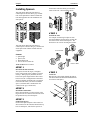
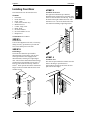
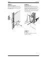
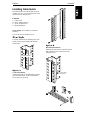
1
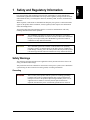
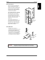
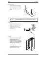
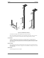
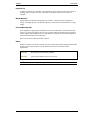
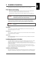
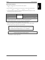
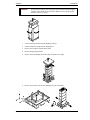
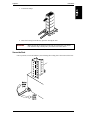
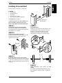
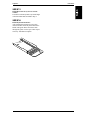
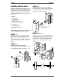
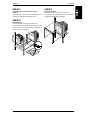
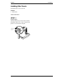
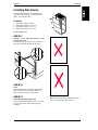
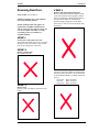
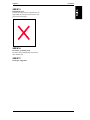
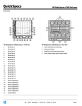
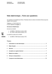
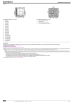
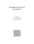
Hewlett-Packard
Rack System/E User’s Manual
J1500A HP Rack System/E41
J1501A HP Rack System/E33
J1502A HP Rack System/E25
HP Part Number 5967-6409
Printed in July 1998
Notice
The information contained in this document is subject to change without notice.
Hewlett-Packard makes no warranty of any kind with regard to this material, including,
but not limited to, the implied warranties of merchantability and fitness for a particular
purpose.
Hewlett-Packard shall not be liable for errors contained herein or for incidental or consequential
damages in connection with the furnishing, performance, or use of this material.
This document contains proprietary information that is protected by copyright. All rights are
reserved. No part of this document may be photocopied, reproduced, or translated to another
language without the prior written consent of Hewlett-Packard Company.
Hewlett-Packard Company
333 Logue Ave.
Mountain View, CA 94043
© Copyright 1998, Hewlett-Packard Company.
Contents
1 Safety and Regulatory Information ................................................................ 1
Safety Warnings................................................................................................. 1
Grounding ...................................................................................................... 1
Leakage Current ............................................................................................ 2
Power Limitations .......................................................................................... 2
Cabinet Stability............................................................................................. 2
Accessories ................................................................................................... 2
2 Description ....................................................................................................... 3
Standard Racks ................................................................................................. 3
Physical Specifications .................................................................................. 4
Accessories........................................................................................................ 7
3 Installation Guidelines................................................................................... 11
Floor Space and Loading................................................................................. 11
Rack Space ................................................................................................. 11
Installing Equipment in the Rack ..................................................................... 11
Ventilation and Heat Dissipation.................................................................. 11
Installing Rail Mounted Equipment into the Rack........................................ 12
Stability ........................................................................................................ 13
4 Procedures ..................................................................................................... 19
Receiving ......................................................................................................... 19
Unpacking, Handling and Moving................................................................ 19
Secure the Rack .......................................................................................... 21
Repackaging the Rack for Shipment ........................................................... 22
Installation of Standard Rack Accessories ...................................................... 22
Installing Universal Shelf.................................................................................. 23
Installing Keyboard Shelf ................................................................................. 24
Installing Monitor Shelf..................................................................................... 26
Installing Filler Panels ...................................................................................... 28
Installing Lifting Hooks ..................................................................................... 29
Installing Spacers............................................................................................. 30
Installing Front Door......................................................................................... 31
Installing Cable Guide...................................................................................... 33
Installing Side Panels....................................................................................... 35
Reversing Rear Door ....................................................................................... 36
iii
1 Safety and Regulatory Information
For your protection, this product has been tested for conformance to various national and
international regulations and standards. The scope of this regulatory testing includes electrical
and mechanical safety, electromagnetic emissions, immunity, ESD, acoustics, and hazardous
materials.
Where required, certifications are obtained from third party test agencies. Certification marks
appear on the product label. In addition, various regulatory bodies require some information
under the headings below.
This product and related documentation must be reviewed for familiarization with safety
markings and instructions before operation.
WARNING
The WARNING sign denotes a hazard. It calls attention to a procedure,
practice, or situation which, if not done correctly or adhered to, could result
in injury. Do not proceed beyond a WARNING sign until the indicated
conditions are fully understood and met.
CAUTION
The CAUTION sign denotes a hazard. It calls attention to an operating
procedure, practice, or situation which, if not done correctly or adhered to,
could damage or destroy part or the entire product. Do not proceed beyond a
CAUTION sign until the indicated conditions are fully understood and met.
Safety Warnings
The following warnings and cautions are applicable to the System/E rack. Please observe all
safety precautions and warnings.
This product has not been evaluated for connection to an IT power system (an AC distribution
system having no direct connection to earth (ground)- according to EN60950.
Grounding
WARNING
This is a safety class I product and has a protective earthing (grounding)
terminal. There must be an uninterruptable safety earth ground from the
main power source to the product’s input wiring terminals, power cord, or
supplied cord set. Whenever it is likely that the protection has been
impaired, disconnect the power cord until the ground has been restored.
1
Chapter 1
Safety and Regulatory Information
Leakage Current
WARNING
Due to types of products that can be installed in this cabinet, there is a risk of
high leakage current (3.5 mA). Reliable ground circuit continuity is vital for
safe operation of this product. To reduce the risk of electric shock, earth
(ground) connection is essential before connecting the power supply. Never
operate this cabinet with the ground conductor disconnected.
Power Limitations
CAUTION
To reduce the risk of overload, do not load any single PDU with more than a
maximum of 16 Amperes. In addition, do not load a single NEMA 5-15 or
IEC-320 receptacle with more than 15 Amperes.
Cabinet Stability
CAUTION
To reduce the risk of cabinet instability, fully extend the anti-tip mechanism
before extending any devices. Extend only one device at a time. Do not
stand or sit on any extended device. Qualified service personnel should do
all non-operator servicing.
Accessories
CAUTION
2
This product is designed for use with specific electrical accessories (i.e.,
PDUs and fans). The use of any other accessory is not recommended or
supported.
2 Description
The HP 19-inch Electronics Industries Association (EIA) racks, options, and accessories are
designed specifically to meet the needs of HP computer and instrumentation customers and
make installing devices in rack mounting systems simple.
Standard Racks
Your standard HP rack is a welded steel frame with removable top, rear doors, casters, leveling
feet and an anti-tip mechanism as shown in Figure 2-1. The top piece is 16-gauge, cold rolled
steel. The base piece is 11-gauge, hot rolled steel. Threaded grounding studs are provided near
the base of every column, and at the top rear.
Racks heights are measured in meters, inches, EIA units, and “U.” 1 EIA unit equals 1 U, which
equals 44.45 mm (1.75 in).
Internally, rails that hold your equipment lock into slots in the vertical mounting columns and
are fastened to the columns with screws. Columns are numbered for easy placement. The
extendable anti-tip mechanism is bi-directional. An extendible top adds 8U of height. Tietogether kits allow easy, secure mating of cabinets. Tops and doors are perforated for maximized
cooling. Tied together racks with the accessories are shown in Figure 2-2.
Top cap
Front
Anti-tip mechanism
Figure 2-1. Two Basic Racks (excluding Rear Door) Tied Together
3
Chapter 2
Description
Figure 2-2. Two Views of Tied racks showing Accessories
Physical Specifications
The physical specifications for the System/E racks are given below.
Packaged
Height
Width
Depth
Weight
1.25m (E25) Rack
1.48 m (58.5 in)
1.016 m (40 in)
1.22 m (48 in)
124.5 kg (274 lbs)
1.6m (E33) Rack
1.84 m (72.5 in)
1.016 m (40 in)
1.22 m (48 in)
133.2 kg (293 lbs)
1.96m (E41) Rack
2.2 m (86.5 in)
1.016 m (40 in)
1.22 m (48 in)
142.7 kg (314 lbs)
1.25m (E25) Rack
1.26 m – 25U
(49.5 in)
59.7 cm (23.5 in)
92.7 cm (36.5 in)
72.7 kg (160 lbs)
1.6m (E33) Rack
1.61 m – 33U
(63.5 in)
59.7 cm (23.5 in)
92.7 cm (36.5 in)
78.6 kg (173 lbs)
1.96m (E41) Rack
1.97 m – 41U
(77.5 in)
59.7 cm (23.5 in)
92.7 cm (36.5 in)
85.5 kg (188 lbs)
Unpackaged
The following parts are standard with every System/E rack.
Top Cap and Forehead
The top cap is 16-gauge, cold rolled
steel (CRS). The top cap and forehead
are attached at the factory. The top of
the rack incorporates a ventilation path
through the roof of the rack and a
convection current heat exit for the heat
generated by the installed equipment.
Heat removal can be augmented with an
extractor fan assembly.
4
Chapter 2
Description
Heavy-duty Columns
The rack columns are a folded design
made of 12-gauge rolled steel that
supports up to 2000 lbs. Running up the
inside of the fold are square mounting
slots for the rails, and screw holes for
securing the rails. The hole placement
conforms to EIA standards.
The mounting columns are welded into
place at the bottom corners of the frame,
and bolted at the top. The columns
accept supporting rails into mounting
slots. Each support rail pair attaches
between the front and rear columns. The
equipment is then mounted on the
support rails.
The mounting columns have prepositioned threaded inserts pressed into
the hexagonal accessories holes in the
front faces of the columns. The inserts
are positioned to accept tie brackets,
hinges, latches, and PDUs.
Threaded inserts
One
EIA unit
or “U”
Anti-Tip Mechanism
Standard on the System/E is a
retractable anti-tip mechanism. Located
at the bottom center of the rack, it
provides temporary additional stability
when installing or removing equipment
components. It is recommended that
you extend the anti-tip mechanism prior
to extending any slide-out equipment.
WARNING
The stability work sheets should be used whenever a new system is
configured, or a change to a system is made, to assure rack stability.
5
Chapter 2
Description
Heavy-Duty Casters
Each System/E is provided with four,
7.6 cm (3 in) diameter, smooth rolling,
heavy-duty urethane casters to facilitate
moves over short distances. The casters
are rated at 454.5 kg (1000 lbs) per
caster.
CAUTION
A fully loaded cabinet’s maximum gross weight of 995 kg (2188 lbs) can
overload a raised floor.
Leveling Feet
Four adjustable leveling feet come with
the rack for stability and leveling.
Levelers are located in each corner to
level and stabilize the rack. For
maximum accuracy, use a level while
adjusting the feet.
Rear Door
The rear door comes installed from the
factory. Standard is a right-opening,
perforated rear door with a lockable
slam latch and sheetmetal catch
providing ventilation and security. The
rear door can be mounted to open from
either the left or the right. They are
perforated for maximum airflow. They
lift on and off their hinges when open to
about 45 degrees. The 1.96 m door
weighs 11.8 kg (26 lbs). The 1.6 m rear
door weighs 9.1 kg (20 lbs). The 1.25 m
rear door weighs 7.7 kg (17 lbs).
6
Chapter 2
Description
Accessories
To complement the functionality of your standard rack, a wide assortment of accessories is available.
These accessories are shown below. These accessories allow you to complete your system with only the
items you require while providing you a certified and tested solution.
Tie-together kit
Cable guide
PDU
Side panel
J1512A
E7723B
E7670A
J1506A
E7671A
J1507A
E7672A
J1508A
J1513A
Front door
J1509A
J1510A
J1511A
E7674A
E7675A
E7676A
Filler panel
J1514A
Lifting hooks
Monitor tray
Keyboard tray
Universal shelf
J1521A
J1519A
J1518A
J1520A
PDUs
The HP Power Distribution Units (PDUs) are designed to provide flexibility for your power
requirements. To provide power to the rack, a PDU must be ordered as an accessory. There are
different types of PDUs available for different voltages. All input leads from the mains, except
safety ground, are interrupted in the event of a short circuit.
The PDUs can be mounted both vertically and horizontally on the rear rack columns, depending
on your rack configuration. If you purchased the bundle containing both the 10 and 16-amp
products, you can connect them to each other with the provided cord. Use the EIA holes for
horizontal mounting, and the accessory holes for vertical mounting.
Each rack can be equipped with up to four PDUs. Each PDU must be purchased as an accessory.
Figure 2-3 shows some PDU Mounting schemes.
7
Chapter 2
Description
Figure 2-3. PDU Attachment Schemes
A maximum of four PDUs can be installed in the 1.6m and 1.96m racks.
Refer to the installation instructions that come with the PDU units E7670A, E7671A, E7672A,
E7674A, E7675A, and E7676A for instructions, details, warnings and safety certificate.
Circuit Protector
The PDU is equipped with a circuit protector for each power phase. If one phase shorts or
overloads, one or both of the circuit protectors in the PDU trip. Unplug the PDU before trying to
locate and correct the electrical problem then reset both circuit protectors on the PDU to restore
power to the rack.
European Cabling
Some products sold in Europe are shipped without a power plug on the end of the PDU cable. It
is the responsibility of the customer to supply the correct installation according to local electrical
and building codes.
Optional Cables
The following option cables are available.
8
Chapter 2
Description
P/N
Volt/Current
Connector
Plug
Type
Length
E7742A
250V / 10AMP
C13
C14
90”
E7743A
125V / 10 AMP
C13
5-15P
90”
E7798A
250V / 16AMP
C19
C20
2.5m
E7799A*
250V / 16AMP
C19
L6-30P
2.5m
E7800A
250V / 16AMP
C19
None
2.5m
E7801A
250V / 16AMP
C19
L6-20P
2.5m
E7802A
120V / 16AMP
C19
5-20P
4.5m
E7803A
250V / 16AMP
C19
L6-20P
4.5m
E7804A
250V / 16AMP
C19
320-C20
4.0m
E7805A*
240V / 16AMP
C19
L6-30P
4.5m
E7806A
240V / 16AMP
C19
none
4.5m
* For use with an Uninterruptable Power Supply (UPS) only.
Front Door
Standard is a right-opening, perforated front door with a lockable slam latch and sheetmetal
catch providing ventilation and security. The rear door can be mounted to open from either the
left or the right.
Support Rails
Some equipment is supported in the rack by support rails running from front to back. The rails
are screwed to the vertical columns
Only after securing a pair of rails with screws can equipment be installed.
The mounting slots in the columns are positioned to make support rail placement convenient in
EIA units.
Rack Lifting Hooks
Four lifting hooks can be fitted to the top of the rack. Together, they can support the weight of a
rack loaded to maximum recommended gross weight. Each hook is capable of supporting 248.6
kg (547 lbs). Maximum recommended gross weight is 995 kg (2188 lbs).
Side Panels
Sectioned side panels are injection molded PC-ABS plastic and come in two sizes: 9 EIA unit
and 8 EIA unit. All three racks use the 9 EIA unit panel at the bottom, and 8 EIA unit panels for
the remainder. Pull out-and-off side panels allow fast and easy access from either side for
installation, servicing, and removal of equipment.
Filler Panels
To ensure adequate cooling in racks using extractor fans, all unused front panel space must be
covered with blank filler panels and the rear door must be closed.
Filler panels are 1 U in height, and snap on and off without tools or mounting hardware.
9
Chapter 2
Description
Keyboard Tray
A pullout keyboard tray is available. The keyboard tray can be installed with either a sitting, or
standing, operator in mind. The tray is mounted on rollers that allow it to be retracted or
extended.
Monitor Mount Kit
An optional universal monitor mounting kit is available. A shelf that can be mounted for a
sitting, or standing operator. The shelf has channels cut from it that accommodate the securing
clamps.
Universal Mounting Rails
Some equipment is supported by and anchored to universal rails made of cold rolled steel that
weigh 2.7 kg (6 lbs) and support up to 68.2 kg (150 lbs). Hollow metal blocks have lips that fit
into the support rails and holes for screws. The blocks are slid into contact with the equipment,
and are then attached to the rail with screws.
Spacers are fit between the rails and the columns.
Ballast
Ballast is available in 30 lb. kits, and may be required when using slide-mounted products and/or
keyboard/ work surface products. Use the stability work sheets to determine ballast
requirements.
10
CAUTION
Do not ship racks with ballast installed.
CAUTION
Always mount ballast in the rear of the rack.
NOTE
The anti-tip assembly is not a substitute for ballast.
3 Installation Guidelines
The following section defines the floor loading requirements, and set up guidelines.
Floor Space and Loading
Observe floor loading requirements (especially raised floors) and ensure adequate space
before moving your Rack System/E, and all safety items while moving.
At maximum gross weight, the floor must be able to support 677-kg/ sq cm (2000 lb./sq
in).
WARNING
It is the customer’s responsibility to determine the floor loading capacities at
the installation site, and for the entire route when moving. Failure to do so
could result in personal injury and/or equipment damage.
Because the weight is concentrated on the four casters, a maximum weight rack requires a
reinforced floor. Hewlett-Packard recommends removing components and moving them
separately when moving a rack over a floor (especially a raised floor) of unknown capacity.
WARNING
Heavily loaded racks may require reinforced tiles or a sub structure on a
raised floor.
Rack Space
Select a location for the rack that will afford adequate space for the door to open freely, and
slide-mounted equipment to be extended.
Door Clearance
The rack requires a minimum of 600 mm (23.6 in) for rear door clearance. The same amount is
required for the front door, if installed.
Cable Access
The base of the rack stops 100 mm (3.9 in) short of the rear door, providing an access path for
power and signal cables.
Installing Equipment in the Rack
Two main considerations should be kept in mind when installing equipment into racks: weight
and balance (especially for slide-mounted equipment), and heat dissipation. This section
includes some worksheets for calculating the weight and balance for slide mounted products and
an optional work surface.
Always install equipment from the bottom to the top to keep the center of gravity as low as
possible. The order that you put them should be based on how well a given piece of equipment
promotes or impedes heat removal, if heat removal is an issue.
Ventilation and Heat Dissipation
Most HP products draw air in through the front and exhaust out the back. The Rack System/E is
designed to accommodate this cooling scheme. Any trapped heat will be convected through the
11
Chapter 3
Installation Guidelines
top perforations. In special cases such as back to back product mounting, the aid of an extractor
fan may be necessary, as illustrated in Figure 3-1.
Figure 3-1. Air Flow through the HP Rack System/E
When the proper system is installed, internal temperature rise is typically less than 15C (27F)
over ambient temperature.
NOTE
Hewlett-Packard recommends that the customer monitor the internal
temperature of the rack. The internal temperature should not exceed the heat
rating of any installed instruments.
Installing Rail Mounted Equipment into the Rack
Equipment is installed by first attaching equipment rails between both front and rear columns, as
shown in Figure 3-2. A clip nut goes behind the rail and a spacer block at the top hole the EIA
unit. This is the same hole the screw lines up with.
Figure 3-2. Attaching Rail to Column
Equipment is placed on the rails, and secured with rear tie-downs, as shown below in Figure 3-3.
12
Chapter 3
Installation Guidelines
Figure 3-3. Attaching Rear Tie-Downs to Rail
Stability
For stability, the sum of the moments above the 32 U critical height must be less than the sum of
the moments below the 32 U critical height. As long as the weight above critical height is less
that the weight below, the moments will most likely cancel. The center of gravity of the cabinet
itself is well below the critical height, adding stability. Because the racks are deeper than they
are wide, they are more stable from front to back, than side to side, as shown in Figure 3-4.
Vertical axis 10 degrees
1.96 m 41 U
1.6m 33U
62.4” 32U
Critical
height
1.25m 25U
X’
Y
X
W
Z
TAN 10 degrees = 11.0 / Z
Z = 11.0 / TAN 10 degrees
Z = 62.4 in ( 1.58 m)
11.0
Figure 3-4. Critical Height
13
Chapter 3
Installation Guidelines
As you can see from the illustration on the right, 1.25 m racks are “unconditionally” stable, and
1.6 m racks are very difficult to overload, as they extend only 1 U above the critical height.
For 1.6 m and 1.96 m racks, add the weights of the units which have centers of gravity above 32
U, then compare the sum of the weights below 32 U. Always configure racks for the majority of
the weight below the critical height.
Assumptions / Disclaimers
The center of gravity for the racks is found in the geometric center. Centers of gravity of
products is assumed to be at their Front/Back, Left/Right centers. Grossly imbalanced equipment
will void the calculations. If doubt exists, stability should be verified by tip-over testing, per UL1950, SECTION 4.1.
Slide-Mounted Products
Slide-mounted products and work surface/keyboard products need weight and balance
calculations performed to determine the need for ballast to reduce the risk of cabinet instability.
The worksheets for both are provided on the following page. If both slide-mounted and work
surface/keyboard products are being used, calculate both and add the results.
To reduce the risk of rack instability when operator serviceable, slide-mounted products are
installed, use the following worksheet to determine the need for additional counterweight ballast.
If there are no operator serviceable, slide-mounted products in the rack, this worksheet can be
ignored.
An operator serviceable, slide mounted product is defined as any product which can be extended
from the rack for servicing without requiring the use of any tool. A product requiring the use of a
tool to facilitate servicing or extending the product is the definition of trained service personnel
serviceable only. When a trained service personnel serviceable only product is extended, the use
of the anti-tip mechanism is required, but counterweight ballast is not. See Figure 3-5.
Also note that some HP products preclude the use of counter weight, due to their mounting
depth. These products are appropriately labeled, and require that the rack anti-tip mechanism
used before the slider product is pulled out. Also, it is recommended that no more than one slider
product be pulled out at one time, to ensure the greatest possible stability.
NOTE
14
No slider products may be withdrawn or extended at the same time the work
surface is in use.
Chapter 3
Installation Guidelines
250 N
or
56.25 lbs
@ max
height = 2 m
Figure 3-5.
Moment Illustration for Slide Mounted Products
Weight and Balance Worksheet:
1. Total the weight of operator serviceable slide-mounted products:
A=________lbs; B=________lbs; C=_________lbs; D=_________ lbs; . . .
2. Total the weight of all fixed and trained service personnel serviceable products:
a=________lbs; b=_________lbs; c=__________lbs; d=_________ lbs; . . .
3. Calculate the moment for both the operator serviceable slide-mounted products (M1) and the
fixed and trained service personnel serviceable products (M2) totals from above:
Model
M1
M2
1.25 m
(A + B + C + D ...) * 1.25 ft
-10.46 ft-lbs + (a + b + c + d + ....) * 1.00 ft
1.6 m
-49.5.4 ft-lbs + (a + b + c + d + ....) * 1.00 ft
1.96 m
-97.2 ft-lbs + (a + b + c + d + ....) * 1.00 ft
M1 = Moment on rack with all operator serviceable slide mounted products extended.
M2 = Moment of all fixed and trained personnel serviceable slide mounted products and rack.
M2 moment calculations assume a 1.00 ft center of gravity for installed products.
If M1 is less than or equal to M2, no additional counter weight is needed.
If M1 is greater than M2, use the formulas below to determine the required counter weight.
Force (in lbs) = M1 - M2 ft-lbs / 2.46 = amount of force required @ 2.46 ft
X = Force lbs / 30 lbs = number of C2790A 30 lbs ballast kits to install, where
“X” is rounded up to the next highest integer, e.g., 1.2 = 2 ballast kits.
Each ballast kit (C2790A) weighs 30 lbs.
15
Chapter 3
Installation Guidelines
Work Surface/Keyboard
To reduce the risk of rack instability when using a work surface or keyboard mounting kit, as
illustrated in Figure 3-6, use the following worksheet to determine the need for additional
counterweight. If there are no work surfaces or keyboard mounting kits in the rack, this
worksheet can be ignored.
NOTE
No slider products may be withdrawn or extended at the same time the work
surface is in use.
Figure 3-6. Moment Illustration for Work Surface / Keyboard
NOTE
16
Always ensure leveling feet have been deployed.
Chapter 3
Installation Guidelines
Weight and Balance Worksheet
1. Maximum extended length of the keyboard/work surface product:
D=_________ft
2. Total the weight of all fixed and trained service personnel serviceable slide-mounted products:
a=________lbs; b=_________lbs; c=_________lbs; d=_________ lbs; . . .
3. Calculate the moment for both the (M1) and the fixed and trained service personnel serviceable
slide-mounted products (M2) totals from above:
Model
M1
M2
1.25 m
180 lbs * D ft
220.2 ft-lbs + (a + b + c + d + ....) * 1.00 ft
1.6 m
246.0 ft-lbs + (a + b + c + d + ....) * 1.00 ft
1.96 m
271.8 ft-lbs + (a + b + c + d + ....) * 1.00 ft
M1 = Moment of rack with 180 lbs of force applied at D ft.
M2 = Moment of all fixed and trained personnel serviceable slide mounted products.
M2 moment calculations assume a 1.00 ft center of gravity for installed products.
If M1 is less than or equal to M2, no additional counter weight is needed.
If M1 is greater than M2, use the formulas below to determine the required counter weight.
Determine required counter weight if M1 is greater than M2:
Force (in lbs) = M1 - M2 ft-lbs / 2.46 = amount of force required @ 2.46 ft
X = Force lbs / 30 lbs = number of C2790A 30 lbs ballast kits to install, where
“X” is rounded up to the next highest integer, e.g., 1.2 = 2 ballast kits.
CAUTION
The anti-tip mechanism is not a substitute for ballast. Use the anti-tip
mechanism when loading or unloading equipment.
Each ballast kit (C2790A) weighs 30 lbs.
17
4 Procedures
This chapter describes unpacking and repackaging your HP rack for shipment, and common
procedures such as positioning racks, installing accessories, and reversing the rear door.
Receiving
This section contains information pertaining to unpacking, inspection, and reshipment.
If the rack package is damaged upon receipt, request that the carrier’s agent be present when the
protective covering is removed. Inspect the rack for damage (scratches, dents, bent pieces, etc.).
If the rack is damaged notify the carrier and the nearest Hewlett-Packard Sales and Service
office immediately.
CAUTION
Do not lift an unpackaged rack with a fork lift
Unpacking, Handling and Moving
After unloading the rack at the shipping dock, check the order documents to the packing or
shipping list to see all parts arrived in good condition. Most likely you will move it on its pallet
to its uncrating point.
Ensure clear passage from the receiving site to the uncrating site. The shipping dimensions and
weights are given below. Casters come attached, so the rack can be rolled when uncrated, to its
next destination.
When you are ready to uncrate and roll your rack, and anytime in the future when moving your
rack, please observe these safety precautions:
Observe floor loading requirements (especially raised floors) and ensure adequate space before
moving your HP rack, and all safety items while moving. At maximum gross weight the floor
must be able to support 677-kg/ sq cm (2000 lb./sq in).
Use the following procedure to remove the rack from the shipping base. One person can perform
this procedure. The sequence of steps is shown below in Figure 4-1.
Figure 4-1. Unpacking Steps
19
Chapter 4
Procedures
WARNING
20
Wear protective glasses while cutting the plastic bands around the shipping
container. These bands are under tension. When cut, they can spring back
and cause serious eye injury.
1.
Cut the polystrap bands around the shipping container.
2.
Lift the cardboard top cap from the shipping box.
3.
Remove the corrugated wrap from the pallet.
4.
Remove the packing materials.
5.
Remove four bolts holding down the ramps, and remove the ramps.
6.
Remove the six bolts from the base attaching the rack to the pallet.
Chapter 4
Procedures
7.
Position the ramps.
8.
Raise the leveling feet all the way up before moving the rack.
WARNING
Make sure that the leveling feet on the rack are raised before you roll the
rack down the ramp, and any time you roll the rack on the casters.
Secure the Rack
Once in position, secure and stabilize your rack using the leveling feet at the corners of the base.
21
Chapter 4
Procedures
Repackaging the Rack for Shipment
Use the original packing material to repackage the empty rack for shipment. If the packing
material is not available, contact your local Hewlett-Packard Sales and Support office.
Before shipment, securely place a tag on the container (and equipment) to identify the owner and
the service to be performed. Include the rack model number.
To repackage the rack, follow the repackage checklist below, and refer to the unpacking
instructions for details.
1.
Assemble the original HP packing materials, or contact your local Hewlett-Packard
Sales and Support office.
2.
Connect the loading ramp to the pallet.
3.
Raise the leveling feet.
4.
Push the rack up the ramp, front first.
5.
Secure the rack to the pallet.
6.
Place the anti-static bag over the rack.
7.
Place the top pad packing material and loading/unloading ramps on the sides of the
rack.
8.
Place the corrugated wrap around the rack.
9.
Put the box top on the box.
10. Secure the top to the pallet with top-to-bottom plastic bands.
Installation of Standard Rack Accessories
This section provides installation procedures for the HP Rack System/E accessories.
22
Chapter 4
Procedures
Installing Universal Shelf
This kit requires 1 EIA unit in your HP rack.
Contents
2
2
1
2
2
Rear Brackets
Sheet Metal Nuts
Plain Shelf
Decorative Gray Screws
Torx 25 Screws with Lock Washers
Tools Needed: Torx 25 Driver
EIA location of
Shelf bottom
NOTE: Extend the rack’s four stabilizer feet
before installing components in the rack.
Remove side panels to install the Plain Shelf.
67(3
Choose EIA location for the Plain Shelf.
Determine the height for the Plain Shelf and
locate EIA number on columns where bottom of
Plain Shelf is to be installed.
67(3
Position and attach Rear Brackets.
Position the bottoms of the Rear Brackets at the
desired EIA location. Install with two non
decorative Torx 25 bolts.
EIA location of
Shelf bottom
67(3
Install Plain Shelf.
Standing in front of the rack and holding the front
of the Plain Shelf, move it to the rear. The pins
pointing in on the Rear Brackets fit into the
channels cut into the back of the Plain Shelf.
Align the front of the shelf at the EIA location.
3
3
3
2
2
2
2
31
3
1
3
0
2
9
8
30
7
Side view
67(3
Install Sheet Metal Nuts in front columns.
In the middle hole of the EIA unit located in Step
1, place sheet metal nuts on the front columns as
shown. (The placement location shown is only an
example.)
67(3
Install Decorative Gray Screws in front
column.
Front holes in the Plain Shelf should align with
Sheet Metal Nuts attached in Step 3. Installation
complete.
23
Chapter 4
Procedures
Installing Keyboard Shelf
This kit requires 2 EIA units in your HP rack.
Contents
2
2
1
2
2
2
Rear Brackets
Sheet Metal Nuts
Keyboard Kit Assembly
Decorative Gray Screws
Torx 25 Screws with Lock Washers
Spare Mouse Cable Clips
67(3
Install Sheet Metal Nuts in front columns.
On the middle hole of the EIA unit located in
Step 1, place sheet metal nuts on the front
columns as shown. (The shown EIA location is an
example location.)
Tools Needed: Torx 25 Driver
NOTE: Extend the rack’s four stabilizer feet
before installing components in the rack.
67(3
EIA location
Choose EIA location for the keyboard.
Determine whether the operator will sit or stand
while using the keyboard, and locate the EIA unit
that places the bottom of the Keyboard Tray at the
correct height.
67(3
Install Keyboard Tray.
Standing in front of the rack and holding the front
of the Keyboard Tray, move it to the rear. The
pins pointing in on the Rear Brackets fit into the
channels cut into the back of the Keyboard Tray.
Align the front of the kit at the EIA location.
67(3
Position and attach Rear Brackets.
Position the bottoms of the Rear Brackets at the
desired EIA location. Install with two non
decorative Torx 25 bolts.
3
3
3
2
1
EIA location
0
Side view
24
Chapter 4
Procedures
67(3
Install Decorative Gray Screws in front
column.
Front holes in the Keyboard Tray should align
with Sheet Metal Nuts attached in Step 3.
67(3
Install keyboard and mouse.
After reading this instruction, remove this
instruction label. Install keyboard and mouse.
Install cable guide. Route the mouse cable
through the guide. Use the spare cable clips as
necessary. Installation complete.
Cable guide
25
Chapter 4
Procedures
Installing Monitor Shelf
This Monitor Rack Mount Kit accomodates all 15”-19”
HP monitors. This kit normally is installed last in a rack
configuration. For convenience and safety install other
components and keyboard kit before installing this
Monitor Rack Mount Kit. This kit requires 11 EIA units
in your HP rack.
67(3
Install Sheet Metal Nuts in front columns.
In the middle hole of the EIA unit located in Step
1, place sheet metal nuts on the front columns as
shown. The location is an example.
Contents
2
2
1
2
2
1
3
Rear Brackets
Sheet Metal Nuts
Monitor Base
Decorative Gray Screws
Torx 25 Screws with Lock
Front Bezel
Clamp Assemblies
EIA location of Monitor
Base bottom
Tools Needed: Torx 25 Driver
NOTE: Extend the rack’s four stabilizer feet
before installing components in the rack.
67(3
Choose EIA location for the Monitor Base.
Determine where you want the bottom of the
Monitor Base. To place the monitor at the top of a
1.96m E-Series rack, use EIA 30. To place the
monitor at the top of a 1.6m E-Series rack, use
EIA 22.
67(3
Install the Monitor Base.
Standing in front of the rack and holding the front
of the Monitor Base, move it to the rear. The pins
pointing in on the Rear Brackets fit into the
channels cut into the back of the Monitor Base.
Align the front of the Monitor Base at the EIA
location.
67(3
Position and attach Rear Brackets.
Position the bottom of the Rear Brackets on the
rear columns at the desired EIA location. Install
with two non-decorative Torx 25 bolts.
3
3
3
2
2
31
2
2
2
3
EIA location for
Monitor Base bottom
1
30
3
0
2
9
8
7
6
26
29
Chapter 4
Procedures
67(3
67(3
Install Decorative Gray Screws in front
column.
Align the tray as shown. Install decorative screws
in front into Clip Nuts installed in Step 3.
Install Front Bezel.
Snap the Front Bezel into place as shown.
Connect monitor cabling. Reinstall the side panels
if applicable. Installation complete.
67(3
Install Monitor.
After reading this instruction, remove this
instruction label. Install the monitor from the side
or rear of the rack. Position Clamp Assemblies to
secure monitor, and tighten.
3
3
3
2
2
2
2
2
3
2
1
3
0
2
9
8
7
6
1
5
0
9
27
Chapter 4
Installing Filler Panels
Each Filler Panel covers 1 EIA unit.
Contents
6 Filler Panels
Tools Needed: None
67(3
Snap into place.
The Filler Panels snap onto the front columns.
Each Filler Panel covers 1 EIA . Position each
panel in a set of EIA holes and push.
Centered on
EIA unit
28
Procedures
Chapter 4
Procedures
Installing Lifting Hooks
The lifting hooks are not meant for permanent
installation, as they interfere with side panels
on top. Once used, they should be removed.
Contents
4 Lifting hooks
67(3
Remove side panels.
Remove the top side-panels on both sides of
the rack.
67(3
Locate bolts.
Locate the bolts at the tops of the columns that
connect the top to the columns. The correct
bolts are positioned on the side of the columns
facing away from the rack.
67(3
Lift rack.
CAUTION
Use all four hooks to
lift the rack. Do not
exceed 547lb per
hook.
67(3
Remove the lifting hooks.
Once the rack has been moved, remove the
lifting hooks, replace the bolts and replace the
side panels. Installation complete.
67(3
Remove bolts and attach hooks.
One column at a time, remove the two bolts,
position the lifting hook, and bolt the lifting
hook to the rack. Don’t remove more than two
bolts at a time.
29
Chapter 4
Procedures
Installing Spacers
the EIA unit. The three holes go towards the
inside of the rack - the hook points down.
This instruction details the placement of
column Spacers and rails into a gray-columnrack for the placement of black-column-rack
rails and equipment. Not all installations use
four Spacers.
May need Spacer
if coming from this style
67(3
Position the rails.
An example of mounting four Spacers onto
rails and columns is shown below. Position the
rails front to back between the Spacers. The
blocks have cut-outs for inserting the rail tabs.
This instruction details the placement of
column spacers and rails into grey-column rack
for the placement of black-column rails and
equipment.
Front or Rear
Contents
2
2
4
4
Spacers, right
Spacers, left
Sheet Metal Nuts
Torx 25 Screws with Lock
31
Tools Needed: Torx 25 Driver
30
67(3
67(3
Install Sheet Metal Nuts.
Place sheet metal nuts over the top hole of the
target EIA unit on columns. Place the nuts with
the protrusion away from the Spacer.
67(3
Position the Spacers.
Position all required Spacers. There must be a
sheet metal nut on the columns behind each top
hole of each Spacer, which is the top hole of
30
29
Determine the hole locations.
The spacers fit into the larger, rectangular
holes, in the insides of the columns, as shown
in Step 3. When properly installed, the three
holes in the spacer align with the three round
holes next to the rectangular hole. Determine
which rectangular mounting hole corresponds
to the EIA unit where you want to install the
spacer. (Each EIA unit is numbered on the
columns of the grey column rack.)
Front or Rear
67(3
Attach all.
Bolt the rail to the column through the Spacer.
The Sheet Metal Nut should be behind the bolt
for each for each Spacer.
Chapter 4
Procedures
Installing Front Door
This instruction is for all front door sizes.
Contents
1 Front Door
1 Latch, Slam Assy
1 Latch -Catch
1 Cable, Door Ground Assy
6 Machine Screws
1 Contact, single, male
2 Hinge, Front
2 Ext Lock Washers
4 Ext Lock Washers w/ nut
3 Bumper Feet
67(3
Install the latch catch.
The right front column has pre-installed
threaded inserts positioned to accept latch bolts
at the 23rd and 27th holes from the top. Position
the latch on the right column and secure with
machine screws. Secure the latch catch to the
left column if installing a right-hinged door.
23 rd
Tools Needed: Torx 25 Driver
67(3
Secure Power.
Turn off all equipment in the rack, if necessary,
taking necessary precautions to prevent data
loss. Secure main power to the rack.
27 th
67(3
Install hinges.
The front left column has pre-installed
threaded inserts for the hinges. The /E series
front right column is also equipped with
threaded inserts, allowing for a right-hinged
door. The left front column has threaded inserts
positioned to accept machine screws at the 11th
and 15th holes down from the top, and the 6th
and 10th holes up from the bottom. Position the
hinges on the left column and and secure with
machine screws.
67(3
Install the door.
The door has pins attached to it that fit onto the
holes in the hinges. Open the door to
approximately 90 degrees and lower the door
pins onto the two hinges.
41
11 th
15 th
10 th
6 th
31
Chapter 4
Procedures
67(3
67(3
Install the latch assembly.
The door has openings for the latch catch.
Remove any installed cover plate, insert the
latch catch, position the backing plate and
secure with screws.
Install ground cable.
A threaded stud is positioned near the Front
Door hinge pin. Attach the ground cable to the
stud with a nut and star washer to the door. A
threaded stud is positioned near the base of
each column. Attach the male connector with a
nut and star washer. Connect the ground cable
to the male connector.
67(3
Re-energize.
Re-energize the equipment, if necessary.
Installation complete.
32
Chapter 4
Procedures
Installing Cable Guide
This instruction is for both old and new style
columns. The new style is presented first. This
instruction is for all rack sizes.
Contents
2
10
4
4
Cable Guide
Screw, Plastic Fastener
Screw, machine M5 x
Sheet Metal Nuts
Tools Needed: Torx 20 Driver (for plastic
fasteners)
Torx 25 Driver (for machine screws)
1HZ6W\OH
Use these instructions for attaching the Cable
Guide to the new style numbered columns,
shown below.
2SWLRQ%
Horizontal attachment.
Install sheet metal nuts over desired holes in
both columns. Secure Cable Guide with
machine screws.
Threaded inserts
2SWLRQ$
Vertical attachment.
Align Cable Guide so the attachment points lie
over threaded inserts. Secure with machine
screws and Torx 25 driver.
Use these holes
for horizontal
33
Chapter 4
2OG6W\OH
Use these instructions for attaching the Cable
Guide to the old style unnumbered column,
shown below.
Procedures
2SWLRQ%
Horizontal attachment.
Install sheet metal nuts over desired holes in
both columns. Secure Cable Guide with
machine screws.
Attach Cable Guide
to these holes
Attach Cable Guide
to these holes
2SWLRQ$
Vertical attachment.
Align Cable Guide so the fasteners fit in the
holes at the outside of the column. Push plastic
fasteners through the Cable Guide into column
holes. If threaded inserts are positioned at
attachment points, secure the Cable Guide with
machine screws.
NOTE: If you push the screw into the
fastener before attaching to the rack
column, the fastener will expand, making it
difficult to attach the cable guide to the
rack.
34
Chapter 4
Procedures
Installing Side Panels
The side snap off and on. All side panels are
eight EIA units in height, except the bottom
panel – it is nine EIA units.
Contents
2
4
6
8
Side Panels (9 EIA)
Side Panels (8 EIA)
Side Panels (8 EIA)
Side Panels (8 EIA)
all kits
for 1.25 m
for 1.6 m
for 1.96 m
Tools Needed: None.
67(3
Position 9 EIA unit Side Panels at the
bottom of the rack.
Position the nine-EIA units so the tab fits into
the lowest column hole that will accept it.
67(3
Push.
The Side Panels snap into place with a small
push. Hook the rear of the Side Panel into
place, and press onto the front column.
67(3
Install all remaining Side Panels.
The Side Panels all install the same way. There
are no gaps between panels when properly
installed.
Hold front and back ends of a Side Panel and
give a firm and gentle tug to remove.
35
Chapter 4
Reversing Rear Door
Tools needed: Torx 25 Driver
NOTE: Extend the rack’s four stabilizer
feet before installing the door.
NOTE: Problems with cable guides, tietogether kits, and PDUs which interfere
with reversing the door must be solved on a
case-by-case basis. Generally, reversing
everything on the rear columns is a
workable solution.
Procedures
67(3
Remove and replace hinges and latch.
Remove hinges and latch catch. Replace them
in the some positions on the opposite column.
The rear columns have identical placements of
threaded inserts. Both rear columns have
threaded inserts positioned to accept hinge
bolts at the 9th and 14th holes from the top and
the bottom
67(3
Secure power and prepare the rack.
Turn off all equipment in the rack, if necessary,
taking necessary precautions to prevent data
loss. Secure main power to the rack.
67(3
Remove ground cable.
Disconnect both ends.
67(3
Remove door.
Open the door to 45 degrees, and lift it off its
hinges.
36
The columns have pre-installed threaded
inserts for latch catch. Both rear columns have
threaded inserts positioned to accept latch bolts
at the listed hole numbers, counting down from
the top.
1.25m rack: Holes 22 and 26
1.6m rack:
Holes 30 and 34
1.96m rack: Holes 38 and 42
Chapter 4
Procedures
67(3
Reinstall the door.
Turn the door upside down. Open the door to
approximately 45 degrees and lower the door
pins into the two hinges.
67(3
Reconnect grounding strap.
Reconnect the grounding strap between the
door and the rack.
67(3
Reenergize equipment.
37