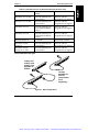
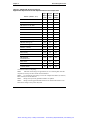
1
Artisan Technology Group is your source for quality
new and certified-used/pre-owned equipment
• FAST SHIPPING AND
DELIVERY
• TENS OF THOUSANDS OF
IN-STOCK ITEMS
• EQUIPMENT DEMOS
• HUNDREDS OF
MANUFACTURERS
SUPPORTED
• LEASING/MONTHLY
RENTALS
• ITAR CERTIFIED
SECURE ASSET SOLUTIONS
SERVICE CENTER REPAIRS
Experienced engineers and technicians on staff
at our full-service, in-house repair center
WE BUY USED EQUIPMENT
Sell your excess, underutilized, and idle used equipment
We also offer credit for buy-backs and trade-ins
www.artisantg.com/WeBuyEquipment
InstraView REMOTE INSPECTION
LOOKING FOR MORE INFORMATION?
Visit us on the web at www.artisantg.com for more
information on price quotations, drivers, technical
specifications, manuals, and documentation
SM
Remotely inspect equipment before purchasing with
our interactive website at www.instraview.com
Contact us: (888) 88-SOURCE | [email protected] | www.artisantg.com
HP NetServer LXr 8500
Rack Assembly and Cabling
Reference Guide
HP Part Number D7054-90015
Printed September 1999
Artisan Technology Group - Quality Instrumentation ... Guaranteed | (888) 88-SOURCE | www.artisantg.com
Notice
The information contained in this document is subject to change without notice.
Hewlett-Packard makes no warranty of any kind with regard to this
material, including, but not limited to, the implied warranties of
merchantability and fitness for a particular purpose. Hewlett-Packard shall not
be liable for errors contained herein or for incidental or consequential damages in
connection with the furnishing, performance, or use of this material.
Hewlett-Packard assumes no responsibility for the use or reliability of its software
on equipment that is not furnished by Hewlett-Packard.
This document contains proprietary information that is protected by copyright. All
rights are reserved. No part of this document may be photocopied, reproduced, or
translated to another language without the prior written consent of
Hewlett-Packard Company.
Windows NT® and Windows 95® are registered trademarks of Microsoft in the
U.S. and other countries.
Torx® is a registered trademark of CamCar/Textron, Inc.
Hewlett-Packard Company
Network Server Division
Technical Communications/MS 45SLE
19055 Tantau Avenue
Cupertino, CA 95052-8059 USA
© Copyright 1999, Hewlett-Packard Company.
Audience Assumptions
The guide is for the person who installs, administers, and troubleshoots LAN servers.
Hewlett-Packard Company assumes you are qualified in the servicing of computer
equipment and trained in recognizing hazards in products with hazardous energy levels
and are familiar with weight and stability precautions for rack installations.
ii
Artisan Technology Group - Quality Instrumentation ... Guaranteed | (888) 88-SOURCE | www.artisantg.com
Contents
1 Preparation for Cabling the NetServer LXr 8500 ........................................ 1
About Cabling the LXr 8500 ........................................................................... 1
Before You Use this Cabling Reference Guide ........................................... 1
The HP NetServer LXr 8500 ...................................................................... 1
Site Preparation............................................................................................. 2
Site Preparation Checklist.......................................................................... 3
Site Preparation -- Circuit Breakers............................................................ 4
Rack Assembly and Cabling Cautions and Warnings ..................................... 5
Unterminated Power Cords Require Licensed Electrician........................... 5
Prevent Electrical Shock............................................................................ 6
Prevent Damage to Components............................................................... 6
Generic Rack Assembly Steps....................................................................... 7
Suggested Method for Building an HP NetServer Rack Installation ............ 7
2 Rack Cabling References .......................................................................... 15
Rack Configuration Tools............................................................................. 15
Power Cabling References and Guidelines .................................................. 15
Power Considerations for the HP NetServer LXr 8500 ............................. 15
Power Cables and Components Available ............................................... 16
Power Distribution Units .......................................................................... 18
Guidelines for Powering the LXr in a Rack ............................................... 21
Power and Current for Estimating Supply Needs...................................... 22
Data Cabling References and Guidelines..................................................... 25
Key Cabling Guidelines Used in Developing a Rack Layout ..................... 25
Cable Guide Placement Considerations Due to Data Cable Lengths........ 25
Cooling Requirements for the LXr 8500 ....................................................... 26
3 Procedure for Connecting and Routing Cables to the LXr 8500 ............. 27
Step 1: Prepare to Cable the HP NetServer LXr 8500 .................................. 27
Assess How Components Will be Connected to the Server...................... 27
Attach Cable Guide to Rack Column........................................................ 27
Mount the Cable Management Arm ......................................................... 27
Mount Power Distribution Units................................................................ 28
Step 2: Connect the LXr 8500 Data Cables to Peripheral Components......... 28
Plan Data Connections ............................................................................ 28
iii
Artisan Technology Group - Quality Instrumentation ... Guaranteed | (888) 88-SOURCE | www.artisantg.com
Contents
Overview of LXr 8500 Data Connections.................................................. 28
Attach Data Cables to the Server............................................................. 30
Attach Data Cables to Other Components ............................................... 32
Step 3: Cable the LXr 8500 for Power .......................................................... 32
Attaching Server and Component Power Cables...................................... 32
Determining and Balancing Current Draw on Two Circuits in One Rack ... 33
208V PDU Rack Power Configurations .................................................... 34
230/240V PDU Rack Power Configurations ............................................. 37
Redundant Power Configuration .............................................................. 39
High Density Configuration ...................................................................... 41
Step 4: Managing and Routing Cables......................................................... 42
Using the Cable Management Arm and the Cable Guides........................ 42
Route and Tie Cables into the Management Arm ..................................... 42
Step 5: Powering Up and Powering Down the Components in the Rack....... 45
Power Up Sequence................................................................................ 45
Power Down Considerations.................................................................... 45
A Cabling Checklist ...................................................................................... 47
B Considerations in Mounting the Redundant Switch ................................ 49
Index............................................................................................................... 53
iv
Artisan Technology Group - Quality Instrumentation ... Guaranteed | (888) 88-SOURCE | www.artisantg.com
1 Preparation for Cabling the
NetServer LXr 8500
About Cabling the LXr 8500
NOTE
A checklist for the cabling process is included in Appendix A.
Before You Use this Cabling Reference Guide
This HP NetServer LXr 8500 Rack Assembly and Cabling Reference Guide
assumes that you have the rack assembly process completed, have mounted the
HP NetServer LXr 8500, and are ready to cable the components in the rack
enclosure.
If you want a high-level checklist to use in this process, see Appendix A.
For instructions on how to install the HP NetServer LXr 8500 in a rack, consult
the Installation Road Map shipped with your rack or the Installation Guide
shipped with your NetServer unit.
NOTE
For instructions on how to assemble other components in a
rack, please find and follow the documentation shipped with
your rack components. If there is no such documentation with
your rack and components, check the separately orderable
installation kit. Or, use the generic rack assembly process
described in this chapter.
The HP NetServer LXr 8500
This Cabling Reference Guide is for the rack-optimized HP NetServer LXr 8500
shown in Figure 1-1.
1
Artisan Technology Group - Quality Instrumentation ... Guaranteed | (888) 88-SOURCE | www.artisantg.com
Chapter 1
Preparation for Cabling the HP NetServer LXr8500
Figure 1-1. The HP NetServer LXr 8500
Site Preparation
You may want to copy and use the site preparation checklist in this section (Table
1-1). Doing so before you begin to install and cable the NetServer may reveal
actions you can take to support your success. Also be sure to read the section on
site preparation of circuit breakers.
2
Artisan Technology Group - Quality Instrumentation ... Guaranteed | (888) 88-SOURCE | www.artisantg.com
Chapter 1
Preparation for Cabling the HP NetServer LXr8500
Site Preparation Checklist
Table 1-1. Site Preparation Checklist
HP NetServer General Guidelines
Logical and physical network design provided
Server configuration parameters determined
Disk partition and directory structure determined
Required incoming power and data cabling in place
Working LAN, one working client, one working printer available (if integrating into an
existing network)
Software license requirements met
Networking peripherals connected
Floor
Ensure the floor where the NetServer rack is to be installed is level
Assess floor strength and ensure it is sufficient to support the type of rack you have
ordered. (See the rack documentation included with your rack.)
Ensure sufficient area to accommodate your rack, including up to 24 inches (600 mm) rear
door clearance and 36 inches (900 mm) front door clearance.
Power
Correct size, type, and rating of receptacles, circuits, and circuit breakers; see the section
entitled “Site Preparation: Circuit Breakers.”
Locate close enough to power sources so that power cords will reach
If raised floor, need floor tile(s) with a cutout for cables, all posts electrically grounded
Facility for grounding each rack to earth connection to ensure earth ground continuity for
circuits to be used for rack mounted equipment
3
Artisan Technology Group - Quality Instrumentation ... Guaranteed | (888) 88-SOURCE | www.artisantg.com
Chapter 1
Preparation for Cabling the HP NetServer LXr8500
Table 1-1. Site Preparation Checklist (Continued)
Environment and Space Requirements
Must meet OSHA, local code, and HP specifications for safety and supportability (3 feet
minimum access in front and rear of electrical cabinets)
Side access of 24 inches improves cable routing and management
24 hour air conditioning (68 - 72 deg. F; 20 - 22 deg. C, 40 - 60% RH)
Table or work space big enough for console terminal and user guides
Bookshelf for documentation
Area to store equipment until time of installation
Ensure all equipment and/or shipping pallets can fit through doorways, hallways, and
into and out of elevators
Data & Voice Communications (Pre-Tested and Verified)
Voice phone located at system console terminal with cord long enough to reach all parts
of the rack installation
Phone line for remote support at each system
Ethernet, FDDI, Token Ring, or other standard
System Parameters
Hostname
IP address
Subnet Mask
Gateway IP Address
Gateway Host Name
DTC Node Name
Hardware Configuration, Cables, and so on
Availability of I/O paths and SCSI addresses for add-on devices
Availability of I/O backplane slots, memory slots, and so on
Valid, supportable configuration for added devices, interfaces, memory, and so forth
Correct type and length of cables, as specified in order documents
Site Preparation -- Circuit Breakers
When you connect the HP NetServer LXr 8500 to an AC power source, the server
temporarily draws a large “inrush current.” This occurs even when the system is in
standby mode. Inrush current is much greater than the server’s normal operating
needs. Generally, your external AC power source can handle the inrush current.
4
Artisan Technology Group - Quality Instrumentation ... Guaranteed | (888) 88-SOURCE | www.artisantg.com
Chapter 1
Preparation for Cabling the HP NetServer LXr8500
If you install several HP NetServers on one circuit, however, precautions are
necessary. For instance, if there is a power failure and power is then restored all
the servers immediately begin to draw inrush current at the same time. If the
circuit breakers on the incoming power line have insufficient capability, they may
trip and thus prevent the servers from powering up.
When preparing your site for installation, allow for the additional inrush current.
Consider the following before installing the server in your environment:
• In North America, a 20-amp-minimum circuit is to be used with one
NEMA AB1 class 14B breaker for each 16-amp Power Distribution Unit
that is to be connected to an HP NetServer LXr 8500.
• In Europe:
◊
For a single LXr 8500 unit in a rack, use a 16-amp-minimum circuit
with one IEC MCB C-type breaker for each 16-amp Power Distribution
Unit.
◊
For multiple LXr 8500 units in a rack, use a 16-amp-minimum circuit
with one IEC MCB D-type breaker for each 16-amp Power
Distribution Unit.
NOTE
Some local codes do not allow a 16-amp device to be
connected to a 16-amp service. Consult a qualified electrician
or local regulatory authority before beginning electrical site
preparation.
Rack Assembly and Cabling Cautions and
Warnings
Unterminated Power Cords Require Licensed Electrician
In some cases in the 230/240V environment, the Uninterruptible Power Supply
(UPS) is shipped with a power cord that is unterminated. The reason is that the
current demand of a fully loaded rack may exceed the demand for the normal
circuit in some countries. Therefore, you should have a qualified electrician or
electrical engineer analyze the current demand for each branch circuit used by
rack mounted equipment. Proper wiring and cord termination are part of the same
process.
5
Artisan Technology Group - Quality Instrumentation ... Guaranteed | (888) 88-SOURCE | www.artisantg.com
Chapter 1
Preparation for Cabling the HP NetServer LXr8500
Prevent Electrical Shock
WARNING
Ensure site electrical circuits have reliable earth grounding.
Never operate products in any rack enclosure with the ground
connector disconnected. Although leakage current from any
one device may be minimal, cumulative leakage current of
equipment mounted in a rack may exceed 5mA, and could
reach 15mA. This level of current can be dangerous, unless a
reliable earth ground is in place. Thus, reliable ground
circuit continuity is vital to safe operation of this system.
WARNING
Prevent shock hazard by disconnecting power and telephone
cords when you service or install components.
Prevent Damage to Components
CAUTION
Rack optimized products are sensitive to static electricity
(ESD). When installing components, take precautions against
ESD damage. Wear a wrist-strap and use a static-dissipating
work surface connected to the server chassis when handling
printed circuit boards, memory devices, and processor chips or
modules. Ensure that the metal of the wrist-strap contacts your
skin and that the alligator clip is attached to a static-neutral
surface.
CAUTION
Power up the components one at a time. Turning on an entire
rack at one time may create damaging and dangerous
electrical surges that could trip circuit breakers in the system.
Follow instructions in the section entitled “Power Up
Sequence” at the end of Chapter 3 to minimize current inrush.
6
Artisan Technology Group - Quality Instrumentation ... Guaranteed | (888) 88-SOURCE | www.artisantg.com
Chapter 1
Preparation for Cabling the HP NetServer LXr8500
Generic Rack Assembly Steps
Suggested Method for Building an HP NetServer Rack Installation
1. Check Site Preparation
Use the Site Preparation Checklist in this chapter to be sure that all necessary
preparations have been completed, including:
• floor level and assessed for sufficient strength and space
• network and software guidelines met
• site electrical power supply set-up complete
• environmental and space requirements met
• data and voice communications pre-tested
• system parameters correctly configured
• hardware and cables order checked
2. Receiving
CAUTION
Units are heavy, often weighing between 85 and 180 lb. (50
and 110 kg). Do not attempt to move or install such units
without help. Also, remove power supplies and hard disk
drives to minimize the amount of weight to be lifted.
Compare the order documents to the packing list or to a list of boxes received.
Check to see that all parts are present. Unpack the HP NetServer and external
storage and tape backup units (if any were ordered).
NOTE
Save the boxes and packaging materials if you intend to reship
the units and rack.
7
Artisan Technology Group - Quality Instrumentation ... Guaranteed | (888) 88-SOURCE | www.artisantg.com
Chapter 1
Preparation for Cabling the HP NetServer LXr8500
3. Prepare Rack Enclosures for Assembly
WARNING
A tip-over hazard exists. Rack enclosures are shipped upright
and are top-heavy. Never move enclosures without adequate
equipment and assistance. Use caution to prevent rack from
falling over and causing potential damage or injury.
If you receive pre-configured units, follow assembly instructions from the
supplying organization first, if you have them. Otherwise, continue with this set of
instructions.
4. Move Rack Enclosures and Other Units to Installation Location
WARNING
Whenever you lift equipment, limit the amount of weight each
person picks up. Lift with your legs, not with your back.
Use two or more people and the proper equipment to move the rack enclosure,
server, mass storage units, and other components. Stage cartons a few feet from
your assembly and final power-up location.
5. Unpack Rack Enclosures and Hardware, Use Anti-Tip Measures, and Remove
the Shipping Panels
WARNING
Use care in moving the rack down from the pallet. Three
people are required for this step.
1. Follow any pictorial instructions on the outside of the shipping container to
unbox the rack enclosure.
2. Adjust the leveler feet, when present, under each of the four corners of
each rack. Lower each leveler foot to be in firm contact with the floor.
CAUTION
The leveler foot prevent the rack from rolling away when you
install components. Be sure to lower these feet before you put
anything into the rack.
3. Find and extend the anti-tip foot under the rack (or bolt on the anti-tip
mechanism, if included) before you mount any rack equipment on slides.
8
Artisan Technology Group - Quality Instrumentation ... Guaranteed | (888) 88-SOURCE | www.artisantg.com
Chapter 1
Preparation for Cabling the HP NetServer LXr8500
WARNING
When equipment is mounted on slidies, a tip-over hazard
exists. Always take the precautions listed below:
Extend or bolt on the anti-tip foot for each rack before
mounting equipment on slides.
Never extend more than one piece of equipment on slides at a
time.
Reduce weight by removing power supplies and hard disk
drives from servers.
Always use the rack mounting handles that are shipped on
rack optimized units as shown in accompanying instructions.
4. Remove shipping panels, if present, from inside the rack enclosure. Save
panels, screws, and rack nuts if you are going to reship the rack.
6. Unpack Remaining Components
Unpack each component in the order in which you assemble them (from the
bottom of the rack upward). Each package contains rack installation instructions
or a user guide.
NOTE
If an Uninterruptible Power Supply (UPS) is included, plug it
in as soon as you unbox it. Doing so helps ensure batteries are
charged when rack installation is completed.
7. Build Basic Rack Assembly
Position, Tie Together, and Open Up the Rack
1. Determine how rack bays are to be positioned. If two or more racks are to
be tied together, use the optional tie-together kit. Otherwise, skip this step.
Newer models may be tied together before or after equipment is mounted
in them. Follow instructions included with tie-together hardware.
9
Artisan Technology Group - Quality Instrumentation ... Guaranteed | (888) 88-SOURCE | www.artisantg.com
Chapter 1
NOTE
Preparation for Cabling the HP NetServer LXr8500
Older HP Systems racks may require that enclosures to be tied
together before any components are mounted inside them. To
avoid problems, if older rack versions are to be tied together,
do so before installing slide members, rails, shelves, units, or
other hardware. Otherwise, you may have to remove
components from the rack to gain access to the tie-bolt
locations.
2. If present, remove the front and rear doors to increase accessibility inside
the rack. Follow instructions shipped with the rack to do so.
NOTE
Older HP Systems racks may also require door hardware to be
in place before mounting components. If you are using front or
rear doors on older models of the HP Systems Rack, be sure
the hinge and latch hardware is mounted before putting on any
other hardware. This prevents later disassembly.
WARNING
When the back door of a rack is removed, the hinge and latch
catch brackets protrude. To avoid injury, temporarily remove
these brackets prior to installing components into the rear of
the rack.
3. If present, remove side panels to allow better access. Follow instructions
included with the rack to do so.
8. Install Fans If Required and Redundant Switch and UPS First If You Have Them
1. If an extractor fan unit is to be used, install it following instructions which
accompany the unit.
NOTE
Most HP NetServers have an internal fan system. However,
rack doors must be perforated (front and/or rear). In this case,
you do not need an extractor fan.
2. If an Uninterruptible Power Supply (UPS) is used, install the UPS
mounting rails and fasten the unit in place following instructions which
accompany it. Place the UPS equipment in the lowest EIA Units of the
rack. Plug the UPS in to charge the batteries as soon as possible.
10
Artisan Technology Group - Quality Instrumentation ... Guaranteed | (888) 88-SOURCE | www.artisantg.com
Chapter 1
Preparation for Cabling the HP NetServer LXr8500
3. Install the Redundant Switch, if you have one, in one of the configurations
shown in Appendix B.
9. Mount Component in the Rack
Plan Component Locations
Use the original ordering information to locate where each component goes in the
rack.
If the original ordering information is not available, use HP rack configuration
tools to plan the location of each component.
HP NetServer rack configuration tools (for instance, HP Rack Assistant) make
ordering easier and automatically check that orders are complete. These tools can
be found on the HP web site. Use the Search function with the words “rack
configuration tools” at the following URL:
http://www.hp.com/go/netserver
Look for “Ordering NetServers,” “Select a Configuration,” “Configuration
Software,” or “Rack Assistant.”
Mount Each Unit in the Rack Enclosure
1. Position each unit following the original layout used to order the server.
Follow the instructions which accompany each component. If you do not
have the original layout, you can use HP rack configuration tools, available
at HP’s web site, to regenerate it.
2. Rack-optimized HP NetServers and mass storage units have instructions in
their user or installation guides for mounting the units in the rack
enclosure. For other servers and storage units, rack mounting instructions
are included with optional rack-mount kits, if available. See the user or
installation guide or rack-mount kit instruction sheet which accompanies
your unit for details.
CAUTION
To prevent rack tip-over, extend or bolt on the anti-tip foot
before installing units on sliding members. Also prevent rack
tip-over by extending only one piece of equipment at a time
from the front or rear of the rack.
3. You may already have installed the UPS, Redundant Switch, and Power
Distribution Units. Do so now if you have not. Begin at the bottom of the
rack, installing the rack mount kit for the first component just above the
power components. Configuration information and examples are available
in Chapter 2 and 3.
11
Artisan Technology Group - Quality Instrumentation ... Guaranteed | (888) 88-SOURCE | www.artisantg.com
Chapter 1
Preparation for Cabling the HP NetServer LXr8500
NOTE
For both safety and accessibility, always start assembly at the
bottom of the rack and work upward.
4. Be sure to locate and place rack nuts along the front outside face of the
vertical column before placing each component on its rails or base. The
pre-positioning of rack nuts allows the front of the component to be
secured to the front of the rack. (Some units use threaded inserts or bar
nuts, and require no rack nuts to secure the unit to the rack.)
5. Mount each unit on its accompanying rails, brackets, or slides.
CAUTION
A tip-over hazard exists. Servers are heavy and may be
awkward to position on their mounting rails. Therefore,
always minimize the weight to be mounted into the rack by
removing power supplies and hard disk drives.
When each component is correctly secured in the rack, replace disk drives
and power supplies and add the front panel (bezel) to the unit.
6. Proceed with units one by one, from the bottom of the rack to the top. Fill
any gaps with filler panels.
10. Connect and Route Cables
NOTE
Illustrated information about cabling the HP NetServer LXr
8500 in the rack is available in Chapter 3 of this Cabling
Reference Guide, which describes the procedures for
connecting and routing cables.
Generally, do the following to ensure cables are correctly connected and managed:
Prepare to Cable the HP NetServer LXr 8500
• Determine which components will be connected to each server.
• Attach Cable Guides to the rack column. See instructions included with
Cable Guides.
• Attach Cable Management Arm to rear of server and to the rack column.
12
Artisan Technology Group - Quality Instrumentation ... Guaranteed | (888) 88-SOURCE | www.artisantg.com
Chapter 1
Preparation for Cabling the HP NetServer LXr8500
• Determine configurations for and mount the PDU (Power Distribution Unit
or Units).
Connect the LXr 8500 Data Cables to Peripheral Components
• Plan where data connections are to be made.
• Attach data cables to the server. Mark the ends of data cables with colored
tie-wraps and labels supplied with each server. This simplifies attaching
cables later in the procedure.
• Provide sufficient cable length to allow servers to be extended from the
rack for maintenance.
• Attach data cables to their respective components.
Cable the LXr 8500 for Power
• Connect each component to a Power Distribution Unit (PDU).
• Connect each PDU to an Uninterruptible Power Supply (UPS) (optional).
• Connect PDU or UPS --if present--cables to Branch Circuits.
Managing and Routing Cables
• Route cables through the Cable Management Arm and tie-wrap them in
place.
• Route cables through Cable Guide and tie wrap them in place.
Powering Up and Powering Down the Components in the Rack
• Follow the power up sequence. See "Power Up Sequence" in Chapter 3.
• If it becomes necessary to bring the server power down, follow the "Power
Down Considerations" in Chapter 3.
11. Configure the System, Install Doors and Side Panels
At this point, refer to the NetServer user or installation manual and configure the
system.
Install front and rear doors as required, and mount side panels. Look for detailed
instructions and illustrations with the rack enclosure and components.
13
Artisan Technology Group - Quality Instrumentation ... Guaranteed | (888) 88-SOURCE | www.artisantg.com
Artisan Technology Group - Quality Instrumentation ... Guaranteed | (888) 88-SOURCE | www.artisantg.com
2 Rack Cabling References
Rack Configuration Tools
Selected reference material derived from HP’s rack configuration tools is
published in this chapter for convenience including the following:
• necessary and optional components
• rack power subsystem configuration and placement
• current and power requirements
• discussion of component location in the rack
• routing cables through the Cable Management Arm and Cable Guide
• cooling requirements and air flow
HP rack configuration tools are available on the worldwide web. Enter the
following URL in your browser:
www.hp.com/go/netserver
At that Web site, search for "configuration tools". Look for Rack Configuration,
Rack Assistant, and Order Assistant.
You can read about the tools or download copies for installation. Tools can be
used to plan a rack configuration for the components of your system.
Power Cabling References and Guidelines
Power Considerations for the HP NetServer LXr 8500
The HP NetServer LXr 8500 can be configured in either 208 or 230/240 VAC.
Power supply (UPS) and distribution (PDU) components are available to support
these configurations. A Redundant Switch is also available.
Details of power considerations for the HP NetServer LXr 8500 include:
◊
the appropriate power cord for each server is shipped according to
voltage requirements; refer to Table 2-2 for details
◊
available in 200/208 VAC configurations for the U. S. market
15
Artisan Technology Group - Quality Instrumentation ... Guaranteed | (888) 88-SOURCE | www.artisantg.com
Chapter 2
Rack Cabling References
◊
available in either 208 VAC or 230/240 VAC configurations for
international markets
◊
Uninterruptible Power Supply (UPS) models rated at 3000 Watts are
available for either voltage range; or a 2250 Watt UPS is available for
230/240 VAC (see Table 2-1)
◊
for both 208 and 230/240 voltages, two wide range Power Distribution
Unit (PDU) models (rated 10 A and 16 A) are available
(see Figure 2-1)
◊
one or more PDUs can be used in each rack enclosure, depending upon
requirements for power, current, and number of receptacles
(see Table 2-4)
Power Cables and Components Available
When components are installed in a rack, a power supply subsytem for the rack is
required. HP recommends the NetServer LXr 8500 be connected as follows:
• connected to a Power Distribution Unit (PDU)--see Figure 2-1.
• through an Uninterrupible Power Supply (UPS)--see Table 2-1
• to a properly protected branch circuit or circuits--see "Site Preparation-Circuit Breakers" in Chapter 1
NOTE
A Redundant Switch is available for use between the UPS and
the branch circuit or between the PDU and the branch circuit.
More information is listed in Table 2-2 and in Appendix B.
Table 2-2 lists details of the cables, components, plugs and receptacles for the two
rack power supply subsystems for the HP NetServer LXr 8500.
Table 2-1. UPS Models and Power Ratings
Uninterruptible Power Supplies (UPS) Available
Power (VA)1
Power (Watts)2
NS3000RMT3U
3000
2250
NS2200RMI3U
2200
1600
NS3000RMI3U
3000
2250
APC Model
Note 1. Ensure UPS Volt Amps rating is not exceeded. Add power in Volt Amps of each
component and connect no more than those the UPS supports.
Note 2. Also ensure UPS Wattage rating is not exceeded. Add power in Watts of each
component and connect no more than those the UPS supports.
16
Artisan Technology Group - Quality Instrumentation ... Guaranteed | (888) 88-SOURCE | www.artisantg.com
Chapter 2
Rack Cabling References
Table 2-2. LXr 8500 Plugs and Receptacles Reference
208 VAC Mains
230/240V Mains
included
C19 to C20, 2.5 m
included
C19 to C20, 2.5 m
E7742A, 90 inch (2.5 m), C13
to C14
E7742A, 90 inch (2.5 m),
C13 to C14
PDU Model No.
E7671A (16 Amp)
E7672A (16 amp, cord, and
10 amp)
E7671A (16 Amp)
E7672A (16 amp, cord, and
10 amp)
Can PDUs be "Daisy
Chained"?
Yes, 10 amp plugs into 16
amp (use to extend the
number of receptacles)1
Yes, 10 amp plugs into 16
amp (use to extend the
number of receptacles) 1
PDU Linecord style
Detachable
Detachable
PDU linecord for
recommended UPS
E7803A, 4.5m, with NEMA
L6-20P plug to C19
E7804A, 4.0m, with IEC
C20 to C19 plug,
Alternate PDU linecords
for installations without a
UPS
E7803A, 4.5m, NEMA L620P to C19 plug
E7806A, 4.5 m, C19 to
unterminated
E7805A 4.5 m with NEMA
L6-30P to C19
E7804A, 4.5 m, C20 to C19
LXr 8500 Jumper Cord
RackStorage/12 and /12FC
and PDU Jumper Cord
E7809A, 4.5 m, CEE 7/7 C192
UPS APC Model Number
NS3000RMT3U
NS2200RMI3U or
NS3000RMI3U
APC Redundant Switch
between PDU and Branch
Circuits (No UPS)
SU045-1 with captive L6-20P
line cords and E7803A, 4.5 m,
L6-20P to C19 to PDU3
SU044-1, C20 inputs,
country-specific C19 cords,
and E7804A, 4 m, C20 to
C19 jumper cord to PDU4
Redundant Switch between
UPS and Branch Circuit
SU045-1 with captive line
cords, captive UPS L6-20 P
connects to L6-20R in switch3
SU044-1, C20 inputs,
country-specific C19 cords,
and E7804A, 4 m C20 to
C19 jumper cord to UPS4
Note 1. Limit the 10-amp PDU to 10 amps of capacity, plug it into the 16-amp PDU, and
limit both together to 16 amps of capacity.
Note 2. The CEE 7/7 cord is fused for 13-amp loads, and limits the PDU to 13 amps of total
supply.
Note 3. The circuit load should be limited to 3000 VA when this switch is used.
Note 4. The circuit load should be limited to 3000 VA when this switch is used.
17
Artisan Technology Group - Quality Instrumentation ... Guaranteed | (888) 88-SOURCE | www.artisantg.com
Chapter 2
Rack Cabling References
Power Distribution Units
Two types of Power Distribution Units (PDU) are currently available for the LXr
8500, as follows:
◊
The wide-range 200/240 VAC PDU (HP product number E7671A) fits
either horizontally between the columns of the rack or vertically along
the outside edge of the vertical column. See Figure 2-2.This PDU is
rated 16 amps and has six available C-13 receptacles and two C-19
receptacles.
◊
A wide-range 200/240 VAC, 10-amp extension (HP product number
E7670A) can be plugged into the 16-amp unit to extend the number of
C-13 receptacles by an additional 10. This accessory also allows
positioning of receptacles at various levels in the rack. (To order the
16-amp unit with its 10-amp extension and jumper cable, order HP part
number E7672A.)
NOTE
The extension PDU (E7670A) only increases the number of
available receptacles. The total current carrying capacity still is
limited to 16 amps for the two PDUs, when daisy chained. In
addition, the extension PDU is limited to carrying only 10
amps.
Placement of PDU
To determine where the PDU mounts, eliminate positions directly behind
equipment listed in Table 2-3. (PDUs conflict with these units when mounted in
the same space). Then decide the most convenient location. The PDU can be
mounted vertically using the non-EIA mounting holes on the outer edges of the
vertical columns. Or it can be mounted horizontally between the columns.
When monitor and UPS units are present, the PDU can be horizontally mounted
across the rack opening, behind one of these units. However, PDUs can also be
mounted vertically on the opposite side of the rack from the door hinges.
18
Artisan Technology Group - Quality Instrumentation ... Guaranteed | (888) 88-SOURCE | www.artisantg.com
Chapter 2
Rack Cabling References
Table 2-3. PDU Placement is not Recommended behind These Units
HP Product Name
Can PDU Be Mounted
Behind?
Reason
HP NetServer LXr 8500
Horizontal Mounting Not
Recommended
Interferes with HotSwappable Power Supplies
HP NetServer LXr 8000
Horizontal Mounting Not
Recommended
Interferes with HotSwappable Power Supplies
HP NetServer LH 3r
Horizontal Mounting Not
Recommended at Bottom
of LH 3r
Interferes with HotSwappable Power Supplies
HP NetServer LH 4r
Horizontal Mounting Not
Recommended at Bottom
of LH 4r
Interferes with HotSwappable Power Supplies
HP FiberChannel 30
Not Feasible
Mechanically conflicts.
HP NetServer Rack
Storage/8
Horizontal Mounting Not
Recommended
Interferes with HotSwappable Power Supplies
HP NetServer Rack
Storage/12 or /12FC
Horizontal Mounting Not
Recommended
Interferes with HotSwappable Power Supplies
Power Distribution Unit Types
10-Amp and
16-Amp, with
Jumper Cord
Available as
E7672A
16-Amp,
Available as
E7671A
(Order Power
Cord
Separately)
Figure 2-1. PDU Configurations
19
Artisan Technology Group - Quality Instrumentation ... Guaranteed | (888) 88-SOURCE | www.artisantg.com
Chapter 2
Rack Cabling References
The 200/240 VAC, wide-range Power Distribution Unit (PDU) can be mounted in
several configurations with the LXr 8500. One of these configurations is shown in
Figure 2-2. Others are listed and illustrated throughout Chapter 3.
How to Position the PDU
Count the receptacles needed for each unit in the rack, notice where the PDUs can
be most conveniently located, and decide whether to orient the PDU vertically or
horizontally.
Horizontal Mounting
of Two PDUs in
a Fully Utilized
Rack
Cable Guides
Mounted on the
Column Across
from the Door
Hinges
Examples of
Data Cable
Routes from
Server to
Connectors on
Other
Components
200-240 VAC WideRange 10-Amp,
19-Inch Power
Distribution Unit,
Installed
Horizontally
Behind the Monitor
(Power Cord
Connections
to Equipment
Are Not
Illustrated
Here)
Data Cables
Routed
through
Cable
Management
Arm
200-240 VAC WideRange 16-Amp
PDU Mounted
Horizontally
Behind the
Uninterruptible
Power Supply
Figure 2-2. Mounting a Pair of PDUs Horizontally (Rear View)
20
Artisan Technology Group - Quality Instrumentation ... Guaranteed | (888) 88-SOURCE | www.artisantg.com
Chapter 2
Rack Cabling References
Guidelines for Powering the LXr in a Rack
Wide Ranging PDU Configurations
Use of four possible 200/240 VAC PDU configurations depends upon the power
requirements of the devices in the rack. Table 2-4 shows how to determine how
many PDUs are supplied with each rack configuration. In configurations that use a
wide-ranging 10-amp PDU, it will always be plugged into a wide-ranging 16-amp
PDU.
Table 2-4. Number, Type, and Ratings of 200/240 VAC PDUs
Wide
Range
16 Amp
1
1
2
2
Wide
Range
10 Amp
(Note 3)
0
1
0
1
Part #s
C-19
Receptacles
C13
Receptacles
Total Amps
E7671A (Note 1)
E7672A (Note 2)
E7671A + E7671A
E7671A + E7672A
2
2
4
4
6
15
12
21
16
16
32
32
Note 1
The E7671A includes one 16 amp PDU. The cord that attaches it to the power
source must be ordered separately, specifying the cord end required.
Note 2
The E7672A includes one 16 amp PDU, one 10 amp PDU, and the cord that
attaches them together. The cord that attaches the 16 amp PDU to the power source must be
ordered separately, specifying the cord end required.
Note 3
The 10-amp PDU can be ordered as an accessory using part number E7670A.
The cord that connects it to the 16-amp PDU must be ordered separately.
Guidelines for PDU Placement
Your wide-range PDU configuration is determined using Table 2-4 and by
application of the following guidelines:
1. The first configuration in the list in Table 2-4 that meets receptacle
count, current requirements, and power requirements is recommended
by rack configuration tools and supplied, unless the purchaser has overridden this choice.
2. The total power drawn by all components in the rack is accumulated by
rack configuration tools, and a second UPS is recommended if wattage
of the first is exceeded.
3. One 16-amp PDU is supplied for each Uninterruptible Power Supply
(UPS) in a rack.
4. (a) When several HP Rack Storage/8 or Rack Storage/12 units are in
the same rack, use of two wide-range 16-amp and one wide-range 1021
Artisan Technology Group - Quality Instrumentation ... Guaranteed | (888) 88-SOURCE | www.artisantg.com
Chapter 2
Rack Cabling References
amp PDU may not provide sufficient receptacles. In this case, use the
Y-cable to connect HP Rack Storage/8 or Rack Storage/12 units to the
PDUs.
(b) When required, a pair of Y-cables are supplied per pair of Rack
Storage/8 or Rack Storage/12 units. That is, two Y-cables are supplied
for two units.
(c) Each Y cable connects either the two right power receptacles or the
two left power receptacles of a pair of HP Rack Storage/8 or Rack
Storage/12 units to one receptacle on the PDU.
Table 2-5. Receptacles Needed for Units
Component
Receptacles Required
HP NetServer LXr 8500
one C19
HP Rack Storage/12
two C13 or use Y-Cable*
All other devices
one C13
* Two Y-Cables may be used to connect two HP Rack Storage/8 or Rack
Storage/12 units to two C13 receptacles.
Power and Current for Estimating Supply Needs
When plugging devices into a PDU and UPS, do not exceed the current capacity
of the PDU nor the power output UPS. Tables 2-6 and 2-7 show the current
requirements of the common rack mounted devices.
Rack configuration utilities available from HP can help you plan the layout of
your rack. Full parts lists as well as diagrams of component positions are
available. Refer to these if they are available. (See "Rack Configuration Tools" in
this chapter.)
22
Artisan Technology Group - Quality Instrumentation ... Guaranteed | (888) 88-SOURCE | www.artisantg.com
Chapter 2
Rack Cabling References
Table 2-6. 208 VAC Power and Current:
Approximate Requirements of Rack Optimized Devices and Components
Input
Power
(VA)
Input
Power
(W)
208v
IRMS
(Amps)
HP NetServer LXr 85004
1121
1077
5.6
HP NetServer LPr
640
285
3.2
HP NetServer LXr 80004
1121
1077
5.6
HP NetServer LH 4r
1130
1100
5.7
HP NetServer LH 3r
650
626
3.2
HP NetServer LXr Pro8
980
970
4.9
HP NetServer LXr Pro
450
446
2.3
HP Fibre Channel Hub D6976A
140
125
0.7
HP Rack Storage/12FC
548
537
2.6
HP Rack Storage/12
548
537
2.6
HP Rack Storage/8
211
209
1.1
Monitor (14-inch)
125
88
0.6
Monitor (15-21-inch)
200
140
0.7
DLT Library
140
98
0.7
DLT Mechanism
50
35
0.3
HP SureStore
Autoloader 418
214
150
1.1
DAT 24x6e
16
11.2
0.1
DAT 24e
6
4.2
*
Console Switch
42
29
0.2
Device (Notes 1, 2, 3)
* Indicates less than 0.1 amp rating
Note 1
Indicated current ratings are approximate, for use in selecting PDU and UPS
components, and may not reflect actual measured amounts.
Note 2
For a full list of power ratings, see the rack configuration utilities (for instance,
Rack Assistant) on the HP Web Site.
Note 3
Ratings from previously published estimates are updated.
Note 4
Ratings assume upgrade from HP NetServer LXr 8000 to HP NetServer LXr
8500 with no change to rack power subsystem.
23
Artisan Technology Group - Quality Instrumentation ... Guaranteed | (888) 88-SOURCE | www.artisantg.com
Chapter 2
Rack Cabling References
Table 2-7. 230/240 VAC Power and Current:
Approximate Requirements of Rack Optimized Devices and Components
Device (Notes 1, 2, 3)
Input Input 230/240v
Power Power IRMS
(VA)
(W)
(Amps)
HP NetServer LXr 85004
1121
1077
4.9
HP NetServer LPr
644
285
2.8
HP NetServer LXr 80004
1121
1077
4.9
HP NetServer LH 4r
1120
1100
4.9
HP NetServer LH 3r
650
626
2.7
HP NetServer LXr Pro8
980
970
4.3
HP NetServer LXr Pro
450
446
2.0
HP Fibre Channel Hub D6976A
138
125
0.6
HP Rack Storage/12FC
548
537
2.3
HP Rack Storage/12
548
537
2.3
HP Rack Storage/8
211
209
0.9
Monitor (14-inch)
125
88
0.5
Monitor (15-21-inch)
200
140
0.6
DLT Library
140
98
0.6
DLT Mechanism
50
35
0.2
HP SureStore
Autoloader 418
214
150
0.9
DAT 24x6e
16
11.2
0.1
DAT 24e
6
4.2
*
Console Switch
42
29
0.2
* Indicates less than 0.1 amp rating
Note 1
Indicated current ratings are approximate, for use in selecting PDU and UPS
components, and may not reflect actual measured amounts.
Note 2
For a full list of power ratings, see the rack configuration utilities (for instance,
Rack Assistant) on the HP Web Site.
Note 3
Ratings from previously published estimates are updated.
Note 4
Ratings assume upgrade from HP NetServer LXr 8000 to HP NetServer LXr
8500 with no change to rack power subsystem.
24
Artisan Technology Group - Quality Instrumentation ... Guaranteed | (888) 88-SOURCE | www.artisantg.com
Chapter 2
Rack Cabling References
Data Cabling References and Guidelines
A series of positioning rules is used in the HP rack configuration tools to help
determine where each component is placed in multiple rack layouts.
Key Cabling Guidelines Used in Developing a Rack Layout
The following discussion is intended to support your understanding of how your
rack order was arrived at. It also discusses how rack layouts affect the attachment
and routing of cables.
This summary of key cabling guidelines reflects information available from HP
rack configuration tools located on the Worldwide Web.
Key guidelines help you to ensure that:
• component placement from rack to rack is consistent
• that the Cable Management Arm is correctly positioned and cables are
routed so that the HP NetServer can be extended for service by trained
personnel
• power supplies and distribution units supplied with the rack assembly can
meet requirements for power, current, and number of receptacles
Cable Guide Placement Considerations Due to Data Cable Lengths
• Data cable lengths limit how far components can be located away from one
another. Component placement depends upon whether the cables are
routed to the left or to the right side of the rack after being connected with
the server. And this in turn depends on Cable Guide placement.
• Cable Guide placement is determined by where the doors are hinged.
Doors can be mounted to swing from either side of the rack. Locate the
Cable Guide on the same side of the rack as the door hinge hardware.
Locate the PDU opposite the cable guide (if mounted vertically), on the
same side as the door latch hardware. PDU location can be changed to
allow other possible cable routing.
• Data connections to devices are made with cables of various lengths. Be
sure to check the component cable length before mouning a component in
the rack.
25
Artisan Technology Group - Quality Instrumentation ... Guaranteed | (888) 88-SOURCE | www.artisantg.com
Chapter 2
Rack Cabling References
• Ensure the monitor cables and mouse cables are long enough to allow the
NetServer to be extended at the same time the keyboard tray is pulled out.
Use locally available extensions if necessary.
• The mounting distances provided in rack configuration tools assume cables
between the servers and connected devices provide for the Cable
Management Arm (for the LXr 8500).
Cooling Requirements for the LXr 8500
The HP NetServer LXr 8500 should be kept at an operating temperature between
68 and 72 degrees F.
Because of the heat generated by the HP NetServer LXr 8500, both the front and
rear doors of the rack have perforated surfaces. Air flow in the rack enters units
through front panels and leaves through the rear. If you are installing the HP
NetServer LXr 8500 in a rack that does not have front and rear perforated doors,
replace the doors on your rack with perforated doors to ensure proper cooling.
Because of the high capacity fans installed in the HP NetServer LXr 8500, no
external exhaust fan is needed with this unit. The rack must have perforated front
and rear doors.
26
Artisan Technology Group - Quality Instrumentation ... Guaranteed | (888) 88-SOURCE | www.artisantg.com
3 Procedure for Connecting and
Routing Cables to the LXr 8500
Step 1: Prepare to Cable the HP NetServer LXr
8500
Assess How Components Will be Connected to the Server
You may find the following steps to be helpful before you begin cabling:
• Review the layout of the rack installation generated with Hewlett-Packard
rack configuration tools, such as Rack Assistant.
• Consider the cabling guidelines discussed in Chapter 2, in the section
"Data Cabling Influence on Component Placement."
• Review the plan for your rack power subsystem, considering how you will
provide failure resistance (see Appendix B on the Redundant Switch),
interim power (see Table 2-1 on Uninterruptible Power Supplies) and
distribution (see the section of Chapter 2 titled "Power Distribution
Units").
Check that you have completed the mounting of the Cable Guides, Cable
Management Arms, and Power Distribution Units as noted below. See Figure 2-2
for an example illustration showing how these three items may look when
mounted..
Attach Cable Guide to Rack Column
Using the instructions included, attach the two Cable Guides to the rack column.
Mount the Cable Management Arm
The HP NetServer LXr 8500 includes a Cable Management Arm. Mount the arm
by following the instructions in the Installation Guide which accompanies your
unit. Further details are included in the section of this chapter titled "Cable
Management."
27
Artisan Technology Group - Quality Instrumentation ... Guaranteed | (888) 88-SOURCE | www.artisantg.com
Chapter 3
Procedure for Connecting and Routing Cables to the LXr 8500
Mount Power Distribution Units
Plan the location of the Power Distribution Unit or Units (PDU) by reference to
amperage, power, and the number of receptacles.. See Chapter 2, the section
entitled "Wide Range PDU Configurations," particularly Table 2-4.
Follow mounting instructions included with your power distribution units. Notice
these cannot be installed behind some equipment. See Table 2-3.
Step 2: Connect the LXr 8500 Data Cables to
Peripheral Components
Plan Data Connections
Plan where data connections are to be made and locate cables to be used. There
are hook-and-loop cable ties and also colored pairs of cable markers with labels in
each server package.
Attach data cables to the boards and ports of the server. Use the colored plastic
cable ties to identify both ends of the cable. Support cables with hook-and-loop
cable ties.
Overview of LXr 8500 Data Connections
This section shows examples for how to connect data cables between the server
and mass storage units. For more information on such connections, see the User or
Installation Guide for the HP Rack Storage/12 or the HP Rack Storage/12FC.
Figure 3-1, "Overview of Data Cabling of the HP NetServer LXr 8500 to the Rack
Storage/12" shows a set-up you might assemble before running HP NetServer
Navigator to configure your server. Figure 3-2 shows a similar set-up for the Rack
Storage/12FC.
See the HP NetServer LXr 8500 Installation Guide for more information on
setting up the system.
CAUTION
Cables with thumb-screws should only be snug or finger-tight.
Excessive tightening could damage the mating connector.
Figure 3-1 shows the connections of the mouse, video, and keyboard cables from
the devices through the HP Console Switch, to the server. Alternate cabling paths
for SCSI cables from the server to the mass storage units are also shown.
28
Artisan Technology Group - Quality Instrumentation ... Guaranteed | (888) 88-SOURCE | www.artisantg.com
Chapter 3
HP NetServer
Lxr 8500
Procedure for Connecting and Routing Cables to the LXr 8500
Rack Storage/12
Single Bus
Configured
Storage
Dashed Lines Indicate Dual Bus
Configured Storage
Figure 3-1. Overview of Data Cabling of the HP NetServer LXr 8500 to an HP
Rack Storage/12
NOTE
Figure 3-1 shows an HP Console Switch, which is not
necessary for configuring the system, but is shown for
informational purposes.
The configuration in Figure 3-1 requires 2 UPS (power
supplies) and 2 PDU (power strip) units at both 208 V and at
230/240 V.
Figure 3-2 shows an HP NetServer LXr 8500 connected in Dual Active Mode to a
Rack Storage/12FC.
29
Artisan Technology Group - Quality Instrumentation ... Guaranteed | (888) 88-SOURCE | www.artisantg.com
Chapter 3
Procedure for Connecting and Routing Cables to the LXr 8500
HP 6-Port Hub
with GBICs
HP NetServer
Lxr 8500
HP Rack Storage/12FC
with GBICs
HP Rack Storage 12
HP Rack Storage/8
Figure 3-2. Overview of Data Cabling of the HP NetServer LXr 8500 to the
Rack Storage/12FC
NOTE
The configuration in Figure 3-2 requires 2 UPS (power
supplies) and 2 PDU (power strip) units at both 208 V and at
230/240 V.
For more information on data cabling with the Rack Storage/12FC, see the HP
Rack Storage/12 FC Installation Guide.
Attach Data Cables to the Server
1. Locate SCSI connections, label both ends of the SCSI cables, and connect
one end of each one to the server. Tighten captive screws on SCSI
connectors to secure the cable connector to the server connector.
30
Artisan Technology Group - Quality Instrumentation ... Guaranteed | (888) 88-SOURCE | www.artisantg.com
Chapter 3
Procedure for Connecting and Routing Cables to the LXr 8500
Figure 3-3. Connecting the Data Cables between the LXr 8500
and Rack Storage/12FC
2. Locate any network and remote management connections from hubs,
routers and other sources and connect their cables to corresponding server
connectors.
3. Locate the cable that will attach the serial port on the Uninterruptible
Power Supply (UPS) (if present) and plug the server end in.
4. Attach the video cable to the video port on the server. Attach the mouse
and keyboard cables to the server. If you are using one keyboard, mouse,
31
Artisan Technology Group - Quality Instrumentation ... Guaranteed | (888) 88-SOURCE | www.artisantg.com
Chapter 3
Procedure for Connecting and Routing Cables to the LXr 8500
and monitor for more than one server, attach the cables for the HP Console
Switch to the server ports of the video card and the mouse and monitor
ports.
Check Whether Cable Lengths Limit Distances between the Server and Storage
Sometimes data cable length or availability limits the distance between a
peripheral component (such as the UPS or video monitor) and its associated
server. Guidelines used by rack configuration tools in generating rack layouts take
possible distance limitations into account. Check power and data cords supplied
with peripherals to ensure you have cables that are long enough to attach each
device.
NOTE
Be sure to leave sufficient data cable length to allow for cable
management. See the section of this chapter “Managing and
Routing Cables” and refer to Figure 3-10.
Attach Data Cables to Other Components
1. Using the colored cable ties and labels attached to each data cable
previously, connect each cable to its component.
2. Fasten cable connectors to each component using captive screws.
Step 3: Cable the LXr 8500 for Power
When all components have been mounted in the rack and their data cables
connected, then the power cables can be attached.
Attaching Server and Component Power Cables
1. Make sure all device power switches are off.
2. Attach the power cords for each device.
◊
Plug power cords into the receptacle in the server.
◊
Ensure sufficient cable to fully extend the server and route cables
through the Cable Management Arm.
◊
Route the cables through the Cable Guide.
◊
Tie bundles of cables using hook-and-loop cable straps.
3. Plug components into the PDU beginning with the components which are
lowest in the rack. If you are using more than one PDU or have a heavily
32
Artisan Technology Group - Quality Instrumentation ... Guaranteed | (888) 88-SOURCE | www.artisantg.com
Chapter 3
Procedure for Connecting and Routing Cables to the LXr 8500
loaded rack, see the section of this chapter entitled "Determining and
Balancing Current Draw on Two Circuits in One Rack."
4. For the sake of easy access to the rear of each component, route the
associated power cords within the same space (the same set of EIA Units)
where the component is located.
Excess cord can be handled by coiling and tie wrapping unneeded length,
and hanging it in the space at the side of the component it connects. When
doing so, be sure you allow sufficient slack for access. Also provide for
components which can be extended, ensuring the coil does not conflict.
5. Plug the PDU(s) into the UPS or into the site power receptacles. When you
are ready to power on the components, see “Power Up Sequence.”
Determining and Balancing Current Draw on Two Circuits in One
Rack
NOTE
Amperage ratings for use in determining and balancing loads
on the Power Distribution Unit are shown in Tables
2-6 and 2-7.
If applicable, use two circuits (each including a Power Distribution Unit and an
optional Uninterruptible Power Supply) in one rack. Attempt to balance the
current drawn through each circuit. Plan to plug in components with smaller
power requirements and connectors so that they alternate between the circuits. In
other words, plug one component into one circuit and the next component into the
other circuit. For instance, see Figures 3-7 and 3-8.
When (in either the 208 or 230/240 VAC case) a 10-amp PDU is daisy-chained to
a 16-amp PDU, determine the load to be placed on each. Plug only those
combinations of components into the 10-amp PDU whose overall total current
draw is less than 10 amperes. Then be sure that the 16-amp PDU total load,
including the daisy-chained 10-amp PDU and any other components, does not
exceed 16 amperes.
Add more PDU-UPS circuits to support higher loads.
33
Artisan Technology Group - Quality Instrumentation ... Guaranteed | (888) 88-SOURCE | www.artisantg.com
Chapter 3
Procedure for Connecting and Routing Cables to the LXr 8500
Location of
Receptacles
for Jumper
Cables for
a Typical
Rack
Monitor
HP Console Switch
Note PDU
Vertically
Mounted
with
Receptacles
Facing
Inward
DLT Library
Mass Storage Unit
(Two Inlets)
HP NetServer
LXr 8500
Mass Storage Unit
(Two Inlets)
Figure 3-4. Power Connection Locations on a Typical Rack (Rear View)
208V PDU Rack Power Configurations
The 208 VAC PDU power configurations appear as shown below in Table
3-1 and Figure 3-5.
Recommended 208 VAC Power Configurations
In the United States, if you are using a UPS, then use PDU model E7671A or
E7672A. Attach the IEC 320 C-19 end of the E7801A cord to the PDU and attach
the L6-20 end of the same cord to the NEMA L6-20 receptacle on the UPS.
34
Artisan Technology Group - Quality Instrumentation ... Guaranteed | (888) 88-SOURCE | www.artisantg.com
Chapter 3
Procedure for Connecting and Routing Cables to the LXr 8500
Alternate 208 VAC Power Configurations
In the 208 VAC case, without a UPS, make sure your power system has the
capacity to support the power and current needs of the components you will
power. (See the section entitled “Site Preparation: Circuit Breakers.) If capacity is
adequate, plug the PDU into a 208 V, L6-20 receptacle.
Table 3-1. 208 VAC Components
Component1
Model
Power
(VA)
Power
(W)
Current
(A)2
E7671A or E7672A
N/A
N/A
max 16
HP NetServer
LXr 85003
D7057A, 500 MHz, 512K Cache
D7133A, 500 MHz, 1MB Cache
D7058A, 500 MHz, 2MB Cache
1121
HP NetServer
Mass Storage
Unit
Rack Storage/12 is D5989A
Rack Storage/12FC is D5991A
547
538
2.6
J1497B
42
29
0.2
208 VAC
PDU
HP Console
Switch
1077
5.6
Note 1
More ratings are listed in Table 2-6. For a full list of power ratings, see the rack
configuration utilities (for instance, Rack Assistant) on the HP Web Site.
Note 2
Indicated current ratings are for use in selecting PDU and UPS components and
may not reflect actual measured amounts.
Note 3
When ordered through select express, the D7057A becomes D7062AV, the
D7133A becomes D7063AV, and the D7058A becomes D7134AV.
Description of the Recommended 208 VAC Configuration
Figure 3-5 shows a UPS connected to the power mains through a captive cord
terminated with an L6-20P plug. The UPS has five receptacles for use in the rack:
two (on the right rear) NEMA 5-15 providing 110 VAC, two L6-20R, and one L630R, providing 208VAC. The E7671A PDU connects to the UPS via a detachable
cord with an L6-20P plug. This cord connects to the PDU with an IEC 320 C-19
plug. The 208 VAC PDU has two IEC 320, C-19 and six IEC 320, C-13
receptacles. A second PDU (E7670A) is available, which can be daisy-chained to
the 16-amp unit, providing ten more C-13 receptacles.
35
Artisan Technology Group - Quality Instrumentation ... Guaranteed | (888) 88-SOURCE | www.artisantg.com
Chapter 3
Procedure for Connecting and Routing Cables to the LXr 8500
Recommended 208 VAC
Power Configuration
for the LXr 8500
HP NetServer
LXr 8500
Rack Mass
Storage Unit
Jumper Cable
Supplied with
NetServer
Uninterruptible
Power
Supply
Jumper Cables
Supplied with
Mass Storage
Units
Captive
L6-20P
Cord
Cable Orderable for
16-Amp PDU,
E7801A L6-20P to
IEC 320 C19, 2.5 m
(Other Configurations Possible)
16-Amp Power
Distribution
Unit, E7671A
Figure 3-5. 208 VAC PDU Configuration
36
Artisan Technology Group - Quality Instrumentation ... Guaranteed | (888) 88-SOURCE | www.artisantg.com
Chapter 3
Procedure for Connecting and Routing Cables to the LXr 8500
230/240V PDU Rack Power Configurations
Configurations for the 230/240 VAC, PDU options are shown in the text below,
Table 3-2, and Figure 3-6.
230/240 VAC Power Configuration
In a country with a 230/240 VAC power system, the wide range (200/240 V) PDU
model E7671A is required. If you are using a UPS, attach the C-19 end of the
accompanying power cord to the PDU and attach the C20 end of the same cord to
the IEC 320 receptacle in the rear of the UPS.
Alternate 230/240 VAC Power Configuration
When the 230/240 VAC PDU is to be used without a UPS in the rack, the PDU is
shipped with a localized power cord.
NOTE
Only localized power cords rated 16A will allow the full 16A
rating of the PDU to be used.
For use with 230/240 VAC power mains, direct connection to a junction box is
usually necessary. In this case, an unterminated power cord is supplied. Be sure to
obey all local electrical code requirements when connecting to the site electrical
power supply.
37
Artisan Technology Group - Quality Instrumentation ... Guaranteed | (888) 88-SOURCE | www.artisantg.com
Chapter 3
Procedure for Connecting and Routing Cables to the LXr 8500
Table 3-2. 230/240 VAC PDU Power and Current
Component1
Model
Power
(VA)
Power
(W)
Current
(A)2
E7671A or E7672A
N/A
N/A
max 16
HP NetServer
LXr 85003
D7057A, 500 MHz, 512K Cache
D7133A, 500 MHz, 1MB Cache
D7058A, 500 MHz, 2MB Cache
1121
HP NetServer
Mass Storage
Unit
Rack Storage/12 is D5989A
Rack Storage/12FC is D5991A
547
538
2.3
J1497B
42
29
0.2
208 VAC
PDU
HP Console
Switch
1077
4.9
Note 1
More ratings are listed in Table 2-6. For a full list of power ratings, see the rack
configuration utilities (for instance, Rack Assistant) on the HP Web Site.
Note 2
Indicated current ratings are for use in selecting PDU and UPS components and
may not reflect actual measured amounts.
Note 3
When ordered through select express, the D7057A becomes D7062AV, the
D7133A becomes D7063AV, and the D7058A becomes D7134AV.
Description of the Recommended 230/240 VAC Configuration
Figure 3-6 shows a UPS connected to the power mains through an attached power
cord (appropriate cords are supplied for each country). The UPS has eight IEC
320 receptacles for use with the rack jumper cords. The E7671A PDU connects to
the UPS via a detachable line cord, which connects to the PDU via a C-19 plug.
This cord connects to the UPS with a C-20 plug. The 200/240 VAC PDU has two
IEC 320, C-19 and six IEC 320, C-13 receptacles for connecting rack jumper
cords.
38
Artisan Technology Group - Quality Instrumentation ... Guaranteed | (888) 88-SOURCE | www.artisantg.com
Chapter 3
Procedure for Connecting and Routing Cables to the LXr 8500
Recommended 230/240 VAC
LXr 8500 Configuration
HP NetServer
LXr 8500
Mass Storage Unit
Jumper Cable
Supplied with
NetServer
Jumper Cables
Supplied with
Mass
Storage
Units
Uninterruptible
Power
Supply
Captive
Unterminated
Cord to be
Terminated Locally
Cable Orderable for 16-Amp
PDU, E7798A, IEC 320 C19
to C20, 2.5 m
(Other Configurations
Possible)
16-Amp Power
Distribution Unit
E7671A
Figure 3-6. 230/240 VAC PDU Configuration
Redundant Power Configuration
Dual Power Supply Example
A dual power supply configuration can be created by ensuring that two different
branch circuits feed two different Uninterruptible Power Supplies, which in turn
power two PDUs. Figure 3-7 shows a dual power cabling example. This example
39
Artisan Technology Group - Quality Instrumentation ... Guaranteed | (888) 88-SOURCE | www.artisantg.com
Chapter 3
Procedure for Connecting and Routing Cables to the LXr 8500
shows two LXr 8500 units powered by two PDUs and two UPS units. Plugging
each UPS into a different branch circuit ensures dual power supply is maintained.
Figure 3-7. Dual Power Supply
40
Artisan Technology Group - Quality Instrumentation ... Guaranteed | (888) 88-SOURCE | www.artisantg.com
Chapter 3
Procedure for Connecting and Routing Cables to the LXr 8500
High Density Configuration
High Density Configuration Example
A high density configuration is illustrated in Figure 3-8. For this example, one 41EIA Unit Rack (a 2-meter HP Systems or HP System/E rack) is completely filled
with power supplies, servers, and storage units. Two mass storage units
“sandwich” each NetServer.
Branch Circuit A
Branch Circuit B
Figure 3-8. High Density Configuration, Block Diagram
41
Artisan Technology Group - Quality Instrumentation ... Guaranteed | (888) 88-SOURCE | www.artisantg.com
Chapter 3
Procedure for Connecting and Routing Cables to the LXr 8500
Step 4: Managing and Routing Cables
Using the Cable Management Arm and the Cable Guides
The HP NetServer LXr 8500 has a single power input cable, but multiple
connections to I/O adapters in the PCI slots. Because power and data cables are
supplied only in one length, measures are necessary to manage the cables attached
to the rear of the server.
A Cable Management Arm ensures the server can be extended for service and
upgrade activities without tangling or disconnecting power and data cables.
Route and Tie Cables into the Management Arm
Instructions for mounting the cable management arm to the rear of the LXr 8500
and to the HP Rack Systems unit are located in the rack mount chapter in the
installation guide. The instructions below assume you have already mounted the
arm.
1. Begin with the HP NetServer LXr 8500 NetServer pushed all the way into
the rack, and the Cable Management Arm flexed. Plug all data and power
cables in and gather them to the corner formed by the back left side of the
NetServer and the flange of the Arm. Use a tie-wrap to secure the cables
there. See Figure 3-9.
42
Artisan Technology Group - Quality Instrumentation ... Guaranteed | (888) 88-SOURCE | www.artisantg.com
Chapter 3
Procedure for Connecting and Routing Cables to the LXr 8500
A. Begin with
the Server all
the way in
B. Plug power and data
cables into the back of
the Server
F. Drape
cables
through
the fingers
of the
Cable
Guide
C. Gather
cables at left
and tie to
Cable
Management
Arm flange
E. Tie wrap cables into the inner
and outer sections of the Arm
D. Arrange cables
through the inner
section of the arm,
around the elbow,
and through the
outer section
Figure 3-9. Routing Cables through the Arm
2. Arrange cables through the slot on the inner section of the Arm. Secure
cables in the cable arm using the hook-and-loop cables supplied with the
NetServer.
3. With the cable arm still in the unextended position, place cables in the
outer section of the arm and secure them with cable ties. Drape the cables
through the fingers of the Cable Guide but do not secure them yet.
4. Prepare to extend the NetServer from the front of the rack by removing the
front bezel and extending the anti-tip foot.
43
Artisan Technology Group - Quality Instrumentation ... Guaranteed | (888) 88-SOURCE | www.artisantg.com
Chapter 3
Procedure for Connecting and Routing Cables to the LXr 8500
WARNING
Before sliding the HP NetServer LXr 8500 out of the rack,
make sure you extend the anti-tip foot from under the front of
the rack.
A tip-over hazard exists, so never slide more than one
component out of the rack at a time.
NOTE
Do not remove the screws that hold the slides to the front
columns of the rack. Slide the NetServer out by grasping the
handle below the LCD control panel.
To PCI
Boards
Extend the Cable Management Arm
to ensure you have enough cable
before routing cables through the
Cable Guide
Figure 3-10. Extend the Server to Adjust Cable Lengths
Fully extend the NetServer (until it clicks) to determine how long the cable
loop needs to be. See Figure 3-10.
5. Adjust cables between the Cable Management Arm and Cable Guide and
tie-wrap them.
6. Gather extra lengths of cable and tie-wrap it into the metal Cable Guides
on the column of the rack.
7. Tighten each of the hook-and-loop tie wraps to ensure they support the
cables correctly. Slide the NetServer in carefully making sure cables do not
44
Artisan Technology Group - Quality Instrumentation ... Guaranteed | (888) 88-SOURCE | www.artisantg.com
Chapter 3
Procedure for Connecting and Routing Cables to the LXr 8500
bind, adjust as necessary. Repeat until the Cable Management Arm extends
and retracts smoothly.
8. Secure the server to the front of the rack with screws and rack nuts and
replace the bezel. See the HP NetServer LXr 8500 Installation Guide for
details.
Step 5: Powering Up and Powering Down the
Components in the Rack
Follow the Power Up Sequence to minimize inrush currents and prevent breakers
from tripping.
Power Up Sequence
1. Power on peripherals one at a time, beginning with the tape back-up unit,
continuing with the mass storage units, monitor, and the rest.
2. If an HP Console Switch is present, it must be on before the server is
turned on. Otherwise the server will not detect all the required components
and will likely report an error.
3. Lastly, power on one server at a time, waiting for fan units in one to spin
up before powering on the next (if more than one is present in the rack).
Power Down Considerations
To power off the equipment, ensure that network users are properly warned. No
specific order is necessary when powering off rack-optimized servers and
associated components. However, to do so in an orderly way, you should bring
down the operating system, then power off peripherals, then turn off servers.
WARNING
The HP NetServer LXr 8500 is connected to standby power
even when power is turned off. Do not open the system for
maintenance except if you have removed the power cord or
powered down the PCI slot in software.
45
Artisan Technology Group - Quality Instrumentation ... Guaranteed | (888) 88-SOURCE | www.artisantg.com
Artisan Technology Group - Quality Instrumentation ... Guaranteed | (888) 88-SOURCE | www.artisantg.com
A Cabling Checklist
Checklist for Cabling Process
Use the Site Preparation Checklist in Chapter 1 to make sure your site is ready.
Read and follow all Rack Assembly and Cabling Warnings in Chapter 1 and in the
Assembly Instructions that accompany your HP Rack.
Assemble (new) or assess (existing) rack equipment.
Check Wattage, Volt Amps, and Amperage to ensure you do not overload your branch
circuits breakers or the rack power supply and distribution equipment. Use tables in
Chapter 2 and illustrations in Chapter 3 for this purpose.
Mount the rack power subsystem, HP NetServer, HP Mass Storage Units, and peripheral
equipment in the rack.
Use instructions which come with them to mount the Power Distribution Unit(s) and the
Cable Guides, and follow instructions in the HP NetServer LXr 8500 Installation Guide
to mount Cable Management Arms.
Attach data cables to the HP NetServer, leave slack for use in cable management, and
connect cables to corresponding components.
Attach power cables to the HP NetServer and other components in the rack, taking care
to balance loads as necessary across PDUs and UPS units. Leave slack enough for use in
cable management. See the section "Determining and Balancing Current Draw" in
Chapter 3.
Route cables through the Cable Management Arm(s) and the Cable Guides, and tie wrap
them in place.
Power up components and then the server, following instructions in Chapter 3.
47
Artisan Technology Group - Quality Instrumentation ... Guaranteed | (888) 88-SOURCE | www.artisantg.com
Artisan Technology Group - Quality Instrumentation ... Guaranteed | (888) 88-SOURCE | www.artisantg.com
B Considerations in Mounting the
Redundant Switch
Table B-1 shows the Redundant Switch in four possible configurations.
The illustrations which follow the table show 208 VAC configuration
wiring diagrams and illustrate the Redundant Switch mounted in the
HP Rack Systems/E.
49
Artisan Technology Group - Quality Instrumentation ... Guaranteed | (888) 88-SOURCE | www.artisantg.com
Appendix B
Considerations in Mounting the Redundant Switch
Table B -1. Components for Use with the Redundant Switch and the LXr 8500
Item
North America: 208/240 VAC
Mains
International1: 230/240V Mains
Application with
UPS
Application
with No UPS
Application with
UPS
Application
with No UPS
APC
Redundant
Switch
Model No..
SU 045-1
SU 045-1
SU 044-1
SU 044-1
Power Cord
from Power
Mains to
Switch
2 Captive Power
Cords with
L6-20P Plugs
2 Captive
Power Cords
with
L6-20P Plugs
2 Detachable
Power Cords,
Country Specific
2 Detachable
Power Cords,
Country
Specific
APC UPS
Model No.
NS3000RMT3U
Not Used
NS3000RMI3U
Not Used
or
NS2200RMI3U2
Power or
Jumper
Cord from
Switch to
UPS
1 Captive Power
Cord with
L6-20P Plug
Not Used
E7804A, 4m, C20
to C19
Not Used
Power or
Jumper
Cord from
Switch to
PDU
Not Used
E7803A, 4.5
m, L6-20P to
C19
Not Used
E7804A, 4m,
C20 to C19
Circuit
Limitations
3000 VA
3000 VA
3000 VA
3000 VA
Note 1. In North America, if 240 VAC is used, refer to these columns.
Note2. This UPS limits circuit to 9.5 Amperes at 2200 VA.
50
Artisan Technology Group - Quality Instrumentation ... Guaranteed | (888) 88-SOURCE | www.artisantg.com
Appendix B
Considerations in Mounting the Redundant Switch
UPS Jumper Cord,
L6-20P to C-19
Branch Circuit A
Branch Circuit B
Captive UPS Cord
with L6-20P
connects to L6-20R
on Redundant
Switch
SKU 045-1
Switch
Captive
Cords, with
L6-20P Cord
Ends
Figure B-1. 208 VAC Configuration of Redundant Switch between UPS
and Branch Circuit
PDU Jumper Cord,
L6-20P to C-19
E7803A
Branch Circuit A
Branch Circuit B
SKU 045-1
Switch
Captive Cords,
with L6-20P Cord
Ends
Figure B-2. 208 VAC Configuration of Redundant Switch between PDU and
Branch Circuit
51
Artisan Technology Group - Quality Instrumentation ... Guaranteed | (888) 88-SOURCE | www.artisantg.com
Appendix B
Considerations in Mounting the Redundant Switch
Note that switches of 230/240 VAC can be mounted in the same way as the 208
VAC models shown. See Table B-1.
Figure B-3. Two UPS and Two Redundant Switches in a Rack
52
Artisan Technology Group - Quality Instrumentation ... Guaranteed | (888) 88-SOURCE | www.artisantg.com
Index
dual power supply configuration, 40
A
air flow in the rack, 26
C
Cable Guide
ensure installed, 27
cable management
ensure the the Cable Guide is in
place, 27
mount the Cable Management Arm,
27
planning for, 25
power cords within occupied area, 33
power cords within same EIA unit,
33
Cable Management Arm
ensure installed, 27
cable routing
cabling guidelines for the LXr 8500,
28
guidelines for server and peripheral
connections, 32
overview of guidelines, 25
overview of procedure, 12
cabling
SCSI cables from LXr 8500 to Rack
Storage/8, 28
capacity
power block diagram, 41
configuring the system
cabling to prepare for, 28
connecting electrical power
unterminated power cords, 5
D
data cables
attach to components, 32
attach to server, 30
overview, 28
E
electrical current requirements
200/208 VAC table of devices, 23
230/240 VAC table of devices, 24
F
fan not required for perforated doors, 10
H
high density configuration, 41
HP Console Switch
use with LXr 8500, 28
HP NetServer LXr 8500
cords, plugs, and receptacles, 16
voltages, 15
HP Rack Assistant, 25
M
multiple rack bays
tie together kit, 9
O
overview
cabling the assembled rack, 12
data cabling, 28
P
PDU. See Power Distribution Unit
placement limitations
due to cable length, 25
power cabling
illustration of rack receptacles, 34
procedure, 32
Power Distribution ensure the PDU is
mounted, 28
Power Distribution Unit
208 VAC illustration, 36
53
Artisan Technology Group - Quality Instrumentation ... Guaranteed | (888) 88-SOURCE | www.artisantg.com
Index
208 VAC, LXr 8500 configuration,
34
208/240 VAC, 10 amp extension, 18
208/240 VAC, 16 amp, 18
230/240 VAC illustration, 37, 39
configuration guidelines, 21
configurations for LXr 8500, 20
determining and balancing load on
double PDUs, 33
models, illustration, 19
placement for the LXr 8500 rack, 18
position in the rack, 20
power down, 45
power off sequence, 45
power strip. See Power Distribution
Unit
power up
minimizing current inrush, 6
power up sequence, 45
R
rack assembly
assemble enclosure, 9
cabling overview, 28
cabling summary, 12
configuration planning, 11
doors and side panels, 13
mount door hinge and latch first, 10
mounting units, 11
preparation, 7, 8
procedure, 11
site preparation, 7
tying two racks together, 10
unpacking the rack, 8
verify and unpack shipment, 7
rack layout, 11
rack power configurations
208 VAC PDU, 35
230/240 VAC, 38
plugs and receptacles, 16
Redimdamt Switch
order of installation, 11
S
safety
anti tip foot use, 8
anti-tip features, 9
care in lifting units, 7
electrical ground connection for the
rack, 6
electrical shock prevention, 6
electrostatic damage (ESD)
prevention, 6
extend one unit at a time, 9
leveler feet, 8
lifting precautions, 8
moving racks safely, 8
preventing component damage, 6
rear latch removal, 10
remove power supplies and disk
packs, 9
use attached rack mounting handles,
9
Safety
rack cabling, 5
shipment to a second location
packaging materials, 7
remove and save shipping panels, 9
side panels
removal of, 10
site preparation, 2
checklist, 3
summary, 7
T
turn on power, 45
U
Uninterruptible Power Supply
installation, 10
plug in early to charge batteries, 9
unpacking
components, 9
rack enclosure, 8
UPS. See Uninteruptible Power Supply.
See Uninterruptible Power Supply
54
Artisan Technology Group - Quality Instrumentation ... Guaranteed | (888) 88-SOURCE | www.artisantg.com
Index
UPS or uninterruptible power supply
unterminated power cord for, 5
V
plugs and receptacles, 16
W
wide ranging switchless power units, 21
voltage options
55
Artisan Technology Group - Quality Instrumentation ... Guaranteed | (888) 88-SOURCE | www.artisantg.com
Artisan Technology Group is your source for quality
new and certified-used/pre-owned equipment
• FAST SHIPPING AND
DELIVERY
• TENS OF THOUSANDS OF
IN-STOCK ITEMS
• EQUIPMENT DEMOS
• HUNDREDS OF
MANUFACTURERS
SUPPORTED
• LEASING/MONTHLY
RENTALS
• ITAR CERTIFIED
SECURE ASSET SOLUTIONS
SERVICE CENTER REPAIRS
Experienced engineers and technicians on staff
at our full-service, in-house repair center
WE BUY USED EQUIPMENT
Sell your excess, underutilized, and idle used equipment
We also offer credit for buy-backs and trade-ins
www.artisantg.com/WeBuyEquipment
InstraView REMOTE INSPECTION
LOOKING FOR MORE INFORMATION?
Visit us on the web at www.artisantg.com for more
information on price quotations, drivers, technical
specifications, manuals, and documentation
SM
Remotely inspect equipment before purchasing with
our interactive website at www.instraview.com
Contact us: (888) 88-SOURCE | [email protected] | www.artisantg.com