1
™
models: 500, 510, 550, 560
Pilot's Guide
OVERVIEW
GPS NAVIGATION
FLIGHT PLANNING
HAZARD AVOIDANCE
ADDITIONAL FEATURES
APPENDICES
INDEX
Copyright © 2009, 2010, 2012 Garmin Ltd. or its subsidiaries. All rights reserved.
This manual reflects the operation of System Software version 4.10 or later. Some differences
in operation may be observed when comparing the information in this manual to earlier or later
software versions.
Garmin International, Inc., 1200 East 151st Street, Olathe, Kansas 66062, U.S.A.
Tel: 913/397.8200Fax: 913/397.8282
Garmin AT, Inc., 2345 Turner Road SE, Salem, OR 97302, U.S.A.
Tel: 503/391.3411Fax 503/364.2138
Garmin (Europe) Ltd, Liberty House, Bulls Copse Road, Hounsdown Business Park,
Southampton, SO40 9RB, U.K.
Tel: 44/0870.8501241
Fax: 44/0870.8501251
Garmin Corporation, No. 68, Jangshu 2nd Road, Shijr, Taipei County, Taiwan
Tel: 886/02.2642.9199
Fax: 886/02.2642.9099
Web Site Address: www.garmin.com
Except as expressly provided herein, no part of this manual may be reproduced, copied, transmitted,
disseminated, downloaded or stored in any storage medium, for any purpose without the express
written permission of Garmin. Garmin hereby grants permission to download a single copy of this
manual and of any revision to this manual onto a hard drive or other electronic storage medium to
be viewed for personal use, provided that such electronic or printed copy of this manual or revision
must contain the complete text of this copyright notice and provided further that any unauthorized
commercial distribution of this manual or any revision hereto is strictly prohibited.
Garmin® and SafeTaxi® are registered trademarks of Garmin Ltd. or its subsidiaries. aera™ is
a trademark of Garmin Ltd. or its subsidiaries. These trademarks may not be used without the
express permission of Garmin.
Jeppesen® is a registered trademark of Jeppesen, Inc.
XM® is a registered trademark of XM Satellite Radio, Inc.
AC-U-KWIK® is a registered trademark of Penton Business Media, Inc.
August, 2012
190-01117-02 Rev. C
Printed in the United States or Taiwan
Warnings, Cautions & Notes
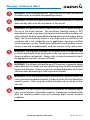
WARNING: When installing the aera™, place the unit so it does not obstruct
the field of view or interfere with operating controls.
WARNING: The indicators represented on the Panel are based on GPS-derived
data and may differ from the instruments in the aircraft.
WARNING: Navigation and terrain separation must NOT be predicated upon
the use of the terrain function. The aera Terrain Proximity feature is NOT
intended to be used as a primary reference for terrain avoidance and does not
relieve the pilot from the responsibility of being aware of surroundings during
flight. The Terrain Proximity feature is only to be used as an aid for terrain
avoidance and is not certified for use in applications requiring a certified
terrain awareness system. Terrain data is obtained from third party sources.
Garmin is not able to independently verify the accuracy of the terrain data.
WARNING: The displayed minimum safe altitudes (MSAs) are only advisory
in nature and should not be relied upon as the sole source of obstacle and
terrain avoidance information. Always refer to current aeronautical charts
for appropriate minimum clearance altitudes.
WARNING: The altitude calculated by aera GPS receivers is geometric height
above Mean Sea Level and could vary significantly from the altitude displayed
by pressure altimeters. Always use pressure altitude displayed by the aircraft
altimeter when determining or selecting aircraft altitude.
WARNING: Do not use outdated database information. Databases used in the
aera system must be updated regularly in order to ensure that the information
remains current. Pilots using any outdated database do so entirely at their
own risk.
WARNING: Do not use data link weather information for maneuvering in,
near, or around areas of hazardous weather. Information contained within
data link weather products may not accurately depict current weather
conditions.
Garmin aera 500 Series Pilot’s Guide
190-01117-02 Rev. C
Warnings, Cautions & Notes
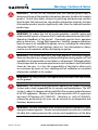
WARNING: Do not use the indicated data link weather product age to
determine the age of the weather information shown by the data link weather
product. Due to time delays inherent in gathering and processing weather
data for data link transmission, the weather information shown by the data
link weather product may be significantly older than the indicated weather
product age.
WARNING: To reduce the risk of unsafe operation, carefully review and
understand all aspects of the aera Pilot’s Guide documentation and the Pilot’s
Operating Handbook of the aircraft. Thoroughly practice basic operation
prior to actual use. During flight operations, carefully compare indications
from the aera to all available navigation sources, including the information
from other NAVAIDs, visual sightings, charts, etc. For safety purposes, always
resolve any discrepancies before continuing navigation.
WARNING: The Garmin aera has a very high degree of functional integrity.
However, the pilot must recognize that providing monitoring and/or self-test
capability for all conceivable system failures is not practical. Although unlikely,
it may be possible for erroneous operation to occur without a fault indication
shown by the aera. It is thus the responsibility of the pilot to detect such
an occurrence by means of cross-checking with all redundant or correlated
information available in the cockpit.
WARNING: For safety reasons, aera operational procedures must be learned
on the ground.
WARNING: The United States government operates the Global Positioning
System and is solely responsible for its accuracy and maintenance. The GPS
system is subject to changes which could affect the accuracy and performance
of all GPS equipment. Portions of the Garmin aera utilize GPS as a precision
electronic NAVigation AID (NAVAID). Therefore, as with all NAVAIDs,
information presented by the aera can be misused or misinterpreted and,
therefore, become unsafe.
WARNING: The data contained in the terrain and obstacle databases comes
from government agencies. Garmin accurately processes and cross-validates
the data, but cannot guarantee the accuracy and completeness of the data.
190-01117-02 Rev. C
Garmin aera 500 Series Pilot’s Guide
Warnings, Cautions & Notes
WARNING: Do not use basemap (land and water data) information for
primary navigation. Basemap data is intended only to supplement other
approved navigation data sources and should be considered as an aid to
enhance situational awareness.
WARNING: Do not rely solely upon the display of traffic information for collision
avoidance maneuvering. The traffic display does not provide collision avoidance
resolution advisories and does not, under any circumstances or conditions, relieve
the pilot’s responsibility to see and avoid other aircraft.
WARNING: Do not rely solely upon the display of traffic information to accurately
depict all of the traffic within range of the aircraft. Due to lack of equipment, poor
signal reception, and/or inaccurate information from aircraft or ground stations,
traffic may be present that is not represented on the display.
CAUTION: Avoid using any chemical or abrasive cleaners on the touchscreen
and/or plastic casing. Clean the touchscreen with a soft, clean, lint-free cloth.
Use water, isopropyl alcohol, or eyeglass cleaner, if needed.
CAUTION: The Garmin aera does not contain any user-serviceable parts.
Repairs should only be made by an authorized Garmin service center.
Unauthorized repairs or modifications could void both the warranty and the
pilot’s authority to operate this device under FAA/FCC regulations.
NOTE: All visual depictions contained within this document, including screen
images of the aera panel and displays, are subject to change and may not
reflect the most current aera system and aviation databases. Depictions of
equipment may differ slightly from the actual equipment.
NOTE: This product, its packaging, and its components contain chemicals
known to the State of California to cause cancer, birth defects, or reproductive
harm. This notice is being provided in accordance with California’s Proposition
65. If you have any questions or would like additional information, please
refer to our web site at www.garmin.com/prop65.
Garmin aera 500 Series Pilot’s Guide
190-01117-02 Rev. C
Warnings, Cautions & Notes
NOTE: Use of polarized eyewear may cause the display to appear dim or
blank.
NOTE: Temporary Flight Restriction (TFR) data is provided by the FAA and
may not be updated outside of normal business hours. Confirm data currency
through alternate sources and contact your local FSS for interpretation of TFR
data.
190-01117-02 Rev. C
Garmin aera 500 Series Pilot’s Guide
Warnings, Cautions & Notes
Blank Page
Garmin aera 500 Series Pilot’s Guide
190-01117-02 Rev. C
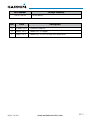
Part Number
190-01194-00
Rev
Date
A October, 2009
Change Summary
Initial release
Description
Production Release
B
August, 2012
Added GDL 39 Support
C
August, 2012
Added GDL 39 Pass-Through and TargetTrend.
190-01117-02 Rev. C
Garmin aera 500 Series Pilot’s Guide
RR-11
Blank Page
RR-12
Garmin aera 500 Series Pilot’s Guide
190-01117-02 Rev. C
Table of Contents
SECTION 1 OVERVIEW................................................................................................................ 1
1.1 Unit Overview..................................................................................................................... 1
1.2 Getting Started................................................................................................................... 2
Battery Installation................................................................................................................ 2
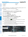
Charging the Battery............................................................................................................. 3
Mounting the aera in the Aircraft........................................................................................... 3
Turning the Unit On/Off......................................................................................................... 4
Changing Modes................................................................................................................... 4
GPS Receiver Status.............................................................................................................. 5
1.3 Operation............................................................................................................................. 7
Basic Navigation Controls...................................................................................................... 7
‘Home’ Screen....................................................................................................................... 8
Selecting a Function............................................................................................................ 15
Scrolling.............................................................................................................................. 15
1.4 Accessing System Functionality.................................................................................... 16
Option Menus..................................................................................................................... 16
Data Entry........................................................................................................................... 16
Waypoint Information Tabs.................................................................................................. 18
1.5 Using Map Displays.......................................................................................................... 18
Map Range......................................................................................................................... 19
Map Panning...................................................................................................................... 20
Map Overlays...................................................................................................................... 22
Map Symbols...................................................................................................................... 23
1.6 System Settings................................................................................................................ 24
Display................................................................................................................................ 24
Sound................................................................................................................................. 25
Additional Settings.............................................................................................................. 26
1.7 Nearest Airport Criteria Settings................................................................................. 28
1.8 Present Position............................................................................................................... 29
Position............................................................................................................................... 29
New Location...................................................................................................................... 29
Simulator Mode.................................................................................................................. 30
SECTION 2 GPS NAVIGATION................................................................................................ 31
2.1 Introduction....................................................................................................................... 31
Data Fields.......................................................................................................................... 32
Numeric Flight Data............................................................................................................ 35
Compass Arc....................................................................................................................... 36
2.2 HSI/Panel............................................................................................................................ 37
Changing the CDI Scale....................................................................................................... 38
Setting the Bug Indicator..................................................................................................... 38
Manually Setting a Course................................................................................................... 39
190-01117-02 Rev. C
Garmin aera 500 Series Pilot’s Guide
i
Table of Contents
2.3 Vertical Navigation (VNAV)............................................................................................ 40
Using the VNAV Feature...................................................................................................... 41
2.4 Map Display Setup........................................................................................................... 43
Map Orientation................................................................................................................. 43
Airports, Navaids, Cities & Roads......................................................................................... 44
Airways............................................................................................................................... 45
2.5 Waypoints.......................................................................................................................... 46
Nearest Information............................................................................................................ 49
Weather and NOTAM Information (Optional)....................................................................... 51
Accessing Additional information......................................................................................... 52
2.6 Direct-to Navigation........................................................................................................ 64
SECTION 3 FLIGHT PLANNING.............................................................................................. 67
3.1 Introduction....................................................................................................................... 67
Data Fields.......................................................................................................................... 67
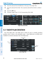
3.2 Flight Plan Creation......................................................................................................... 68
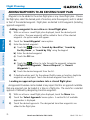
Adding Waypoints to an Existing Flight Plan......................................................................... 70
3.3 Flight Plan Storage.......................................................................................................... 71
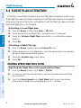
3.4 Flight Plan Activation...................................................................................................... 72
Editing Speed and Fuel Flow................................................................................................ 72
Copying Flight Plans............................................................................................................ 73
Deleting Flight Plans........................................................................................................... 73
Inverting a Flight Plan......................................................................................................... 74
3.5 Approaches........................................................................................................................ 75
Selecting an Approach......................................................................................................... 76
Activating Vectors-to-Final................................................................................................... 78
SECTION 4 HAZARD AVOIDANCE......................................................................................... 79
4.1 Weather.............................................................................................................................. 79
XM® Weather (aera 510 & 560)........................................................................................... 79
XM Satellite Weather Products............................................................................................. 81
Using XM Satellite Weather Products................................................................................... 91
Data Link weather (FIS-B) (all models)................................................................................. 94
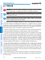
4.2 Terrain............................................................................................................................... 106
Terrain Information............................................................................................................ 107
Obstacle Information......................................................................................................... 107
Terrain and Obstacle Color Code....................................................................................... 108
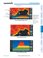
Terrain Views..................................................................................................................... 108
Terrain Alerts & Setup........................................................................................................ 110
4.3 Traffic................................................................................................................................ 112
Traffic Information Service (TIS-A)...................................................................................... 112
Traffic Ground Track .......................................................................................................... 113
Displaying Traffic Data....................................................................................................... 113
Data Link Traffic (GDL 39).................................................................................................. 115
ii
Garmin aera 500 Series Pilot’s Guide
190-01117-02 Rev. C
Table of Contents
SECTION 5 ADDITIONAL FEATURES................................................................................. 127
5.1 SafeTaxi............................................................................................................................ 127
SafeTaxi Cycle Number and Revision.................................................................................. 128
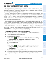
5.2 Airport Directory Data.................................................................................................. 129
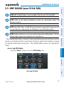
5.3 XM® Radio (aera 510 & 560)......................................................................................... 131
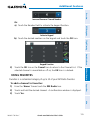
Activating XM Satellite Radio Services............................................................................... 132
Using XM Radio................................................................................................................ 133
SECTION 6 APPENDICES........................................................................................................ 141
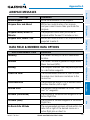
Appendix A: Messages, Alerts & Data Field Options.................................................... 141
Miscellaneous Message Advisories..................................................................................... 141
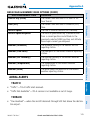
Airspace Messages............................................................................................................ 143
Data Field & Numeric Data Options................................................................................... 143
Aural Alerts....................................................................................................................... 145
Appendix B: Abnormal Operation..................................................................................... 147
Loss of GPS Position.......................................................................................................... 147
Hazard Display with Loss of GPS Position........................................................................... 147
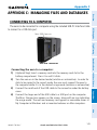
Appendix C: Managing Files and Databases................................................................... 149
Connecting to a Computer................................................................................................ 149
Managing Files................................................................................................................. 150
MicroSD™ Card Use (Optional).......................................................................................... 152
Databases......................................................................................................................... 153
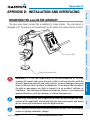
Appendix D: Installation and Interfacing........................................................................ 157
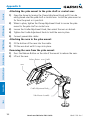
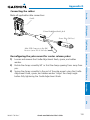
Mounting the aera in the Aircraft....................................................................................... 157
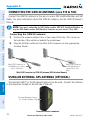
Connecting to a Garmin VHF Comm Radio......................................................................... 161
Information about USB Drivers.......................................................................................... 163
Interfacing........................................................................................................................ 163
Connecting to a GTX 330 Mode S Transponder.................................................................. 165
Connecting to a GDL 39.................................................................................................... 166
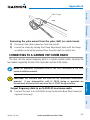
Connecting the GXM 40 Antenna (aera 510 & 560)........................................................... 170
Using an external GPS Antenna (Optional)......................................................................... 170
Appendix E: Battery and Care Information.................................................................... 171
Battery Information........................................................................................................... 171
Changing the Fuse............................................................................................................ 171
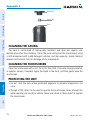
Cleaning the Casing.......................................................................................................... 172
Cleaning the Touchscreen.................................................................................................. 172
Protecting the Unit............................................................................................................ 172
Avoiding Theft................................................................................................................... 173
Registering the Unit.......................................................................................................... 173
Appendix F: General TIS-A Information........................................................................... 175
TIS-A vs. TAS/TCAS............................................................................................................ 175
TIS-A Limitations............................................................................................................... 175
190-01117-02 Rev. C
Garmin aera 500 Series Pilot’s Guide
iii
Table of Contents
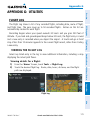
Appendix G: Utilities............................................................................................................ 179
Flight Log.......................................................................................................................... 179
Track Log.......................................................................................................................... 180
Heading Line..................................................................................................................... 183
E6B Calculator.................................................................................................................. 184
Aircraft Profile................................................................................................................... 186
Weight & Balance............................................................................................................. 187
EPE Circle......................................................................................................................... 188
Proximity Waypoints.......................................................................................................... 189
Appendix H: Display Symbols............................................................................................ 191
VFR Symbols..................................................................................................................... 191
IFR Symbols...................................................................................................................... 192
Airspace Symbols.............................................................................................................. 194
Appendix I: Map Datum and Location Formats............................................................. 197
Map Datums..................................................................................................................... 197
Location Formats............................................................................................................... 197
Appendix J: Glossary............................................................................................................ 199
Appendix K: License Agreement and Warranty............................................................. 205
Contact Garmin................................................................................................................ 205
Software License Agreement.............................................................................................. 205
Limited Warranty............................................................................................................... 205
AOPA Airport Directory Notice........................................................................................... 206
AC-U-KWIK LICENSE AGREEMENT..................................................................................... 206
XM Satellite Radio Service Agreement................................................................................ 207
Weather Data Warranty..................................................................................................... 207
FCC Compliance............................................................................................................... 208
Industry Canada Compliance............................................................................................. 208
Index....................................................................................................................................Index-1
iv
Garmin aera 500 Series Pilot’s Guide
190-01117-02 Rev. C
Overview
Overview
SECTION 1 OVERVIEW
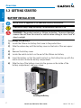
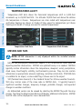
1.1 UNIT OVERVIEW
Power Button
Flight Planning
Headphone/audio-out Jack
(Under Weather Cap)
GPS Navigation
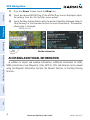
In aviation mode the aera presents GPS-derived analog flight instrumentation,
position, navigation, and hazard avoidance information to the pilot using a 4.3”
QWVGA color display with Touch Screen.
Microphone
Hazard Avoidance
External Antenna Connector (Under Weather Cap)
Additional Features
Mini-USB Connector
MicroSD™ Slot
GPS Antenna
Appendices
Battery Contacts
Speaker
190-01117-02 Rev. C
Index
Release Key: Slide and
Release to Open the Battery
Cover
Serial Number (Under
the Battery)
Unit Overview
Garmin aera 500 Series Pilot’s Guide
1
1.2 GETTING STARTED
BATTERY INSTALLATION
GPS Navigation
Overview
Overview
NOTE: Refer to Appendix E for additional battery information.
CAUTION: Always keep the battery installed when the unit is on.
Flight Planning
WARNING: The product contains a lithium-ion battery. To prevent damage,
remove the unit from the aircraft or vehicle when exiting or store it out of
direct sunlight.
Index
Appendices
Additional Features
Hazard Avoidance
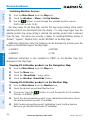
Installing the battery:
1) Locate the lithium-ion battery that came in the product box.
2) Slide the release key until the battery cover on the back of the aera opens
up.
3) Remove the battery cover.
4) Locate the metal contacts on the end of the lithium-ion battery.
5) Insert the battery so that the metal contacts on the battery line-up with the
metal contacts inside the battery compartment.
6) Slide the top of the battery cover into the groove on the inside of the
battery compartment, and press down.
Installing the Battery
2
Garmin aera 500 Series Pilot’s Guide
190-01117-02 Rev. C
Overview
NOTE: While in Charge Mode, the unit draws a current from the aircraft. To
avoid discharging the aircraft’s battery, disconnect the external power cable
from the unit when not in use for several days.
104°F (0° to 40°C).
Hazard Avoidance
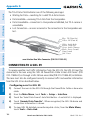
Charging the unit’s battery using the aircraft's power outlet:
1) Mount the aera in the aircraft (refer to Appendix D 'Installation and
Interfacing'), and connect the power cable to the aircraft power outlet
(cigarette lighter receptacle).
2) Route the power cable so that it does not interfere with aircraft operation.
The unit begins charging as soon as external power is applied.
USING CHARGE MODE
The unit will run cooler and may allow more current to be available while in Charge
Mode, when XM is unplugged, the backlight is turned down, etc.
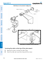
Refer to Appendix D 'Installation & Interfacing' for information on mounting the
aera in the aircraft.
Garmin aera 500 Series Pilot’s Guide
3
Index
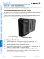
MOUNTING THE aera IN THE AIRCRAFT
Appendices
If you do not want to use the unit, but you would like to charge the battery, you can
put the unit into Charge Mode. Connect the unit to an external power supply. Press
and hold the POWER Button. Instead of completely turning off, the unit now goes
into Charge Mode.
Additional Features
Applying external power to the aera automatically turns on the unit for full operation.
If the battery is present and needs to be charged, the external power source charges
the battery while the unit is in use.
190-01117-02 Rev. C
Flight Planning
Plug the unit into a 12-Volt or 24-Volt connector to charge. The unit can be used
while it is charging. Charge the unit within the following temperature range: 32° to
GPS Navigation
Charge the aera for at least 4 hours before using on battery power. Charge the
battery by connecting the vehicle or aviation power cable, the USB cable, an AC adapter
(optional accessory), or use a battery charger (optional accessory).
Overview
CHARGING THE BATTERY
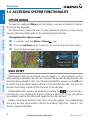
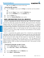
TURNING THE UNIT ON/OFF
Press and hold the
POWER Button to turn the unit on or off.
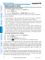
The first time the unit is turned on, the receiver must collect satellite data and
establish its present location. To ensure proper initialization, the aera is shipped from
the factory in AutoLocate mode, which allows the receiver to “find itself” anywhere in
the world.
During initialization, current database information is displayed. Database information
includes valid operating dates, cycle number, and database type. When this information
has been reviewed for currency (to ensure that no databases have expired), the pilot
is prompted to continue.
Touching the Press To Accept Button acknowledges this information, and the
'Home' Screen is displayed.
Additional Features
Hazard Avoidance
Flight Planning
GPS Navigation
Overview
Overview
Database Initialization
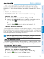
CHANGING MODES
The aera offers two modes for transportation: automotive and aviation.
Appendices
Changing modes:
1) Touch the automotive or aviation icon at the top of the 'Home' Screen.
2) Touch Yes.
Aviation
Automotive
Index
Or:
1) From the 'Home' Screen, touch Tools > Automotive or Aviation (from
automotive mode).
2) Touch Yes.
4
Garmin aera 500 Series Pilot’s Guide
190-01117-02 Rev. C
Overview
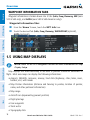
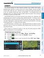
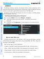
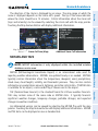
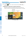
The receiver status displays one of the following conditions:
•Autolocate—Receiver is looking for any satellite whose almanac has been
collected, which can take up to 5 minutes
•Acquiring Satellites—Receiver is looking for and collecting data from satellites
visible at its last known or initialized location, but has not acquired a fix
•Lost Satellite Reception—the receiver is no longer tracking enough satellites for a
2D or 3D fix
Constellation
Diagram
Signal
Strength Bar
45° Above
Horizon
Horizon
Receiver Status
GPS Status
Viewing the GPS status:
Appendices
PRN Number
Location
(Lat/Long)
Additional Features
PRN Number
Hazard Avoidance
•3D GPS Location—At least four satellites have been acquired and a threedimensional fix has been calculated. “3D Differential” appears when you are
receiving DGPS corrections in 3D mode
Flight Planning
•2D GPS Location—At least three satellites have been acquired and a twodimensional location fix has been calculated. “2D Differential” appears when
you are receiving DGPS corrections in 2D mode
GPS Navigation
•Searching the Sky—Receiver is looking for satellites
Overview
GPS RECEIVER STATUS
From the 'Home' Screen, touch Tools > GPS Status.
The
Index
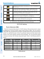
ACQUIRING SATELLITES
bars on the 'Home' Screen indicate the GPS signal strength.
190-01117-02 Rev. C
Garmin aera 500 Series Pilot’s Guide
5
GPS Navigation
Overview
Overview
When the receiver is in the process of acquiring enough satellite signals for
navigation, the receiver uses satellite orbital data (collected continuously from the
satellites) and last known position to determine the satellites that should be in view.
‘Acquiring Satellites’ is indicated as the solution until a sufficient number of satellites
have been acquired for computing a solution.
When the receiver is in the process of acquiring a 3D differential GPS solution, ‘3D
GPS Location’ is indicated as the solution until the 3D differential fix has finished
acquisition.
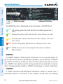
Satellites currently in view are shown at their respective positions on a satellite
constellation diagram. The outer circle of the constellation diagram represents the
horizon, the inner circle represents 45° above the horizon, and the center point shows
the position directly overhead. Each satellite is represented by a square containing the
Pseudo-Random Noise (PRN) number (i.e., satellite identification number).
GPS Status can be helpful in troubleshooting weak (or missing) signal levels
due to poor satellite coverage or installation problems. As the GPS receiver locks
onto satellites, a signal strength bar is displayed for each satellite in view, with the
appropriate satellite PRN number (01-32 or 33-64 for WAAS) below each bar. The
progress of satellite acquisition is shown in three stages, as indicated by signal bar
appearance:
- No bar—Receiver is looking for the indicated satellite
- Gray bar—Receiver has collected the necessary data and the satellite signal can
be used
Appendices
Additional Features
Hazard Avoidance
Flight Planning
SATELLITE INFORMATION
Index
- Green bar—Satellite is being used for the GPS solution
6
Garmin aera 500 Series Pilot’s Guide
190-01117-02 Rev. C
Overview
Overview
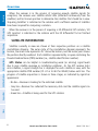
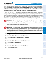
1.3 OPERATION
BASIC NAVIGATION CONTROLS
Touch the following icons to perform the associated function:
Home
Returns to the ‘Home’ screen.
OK
Commits a value edited or selected.
Menu
Displays the context sensitive option menu.
Menu/
Displays the menu; Displays the Direct-to function (touch and hold).
Up
Scrolls up.
Down
Scrolls down.
Hazard Avoidance
Displays the previous page; Returns ‘Home’ (touch and hold).
Direct-to Displays the Direct-to function.
Zooms out.
In
Zooms in.
Additional Features
Out
KEYPAD CONTROLS
Exits the keypad function and accepts the changes.
BKSP
Erases the current data.
Numeric
Displays the numeric only keypad.
Alpha
Displays the alpha and numeric keypads.
Cancel
Cancels a value that has been edited.
Appendices
OK
Flight Planning
Back
GPS Navigation
The controls on the touchscreen change dynamically depending on the function
displayed.
Index
190-01117-02 Rev. C
Garmin aera 500 Series Pilot’s Guide
7
Overview
Overview
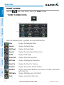
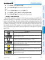
‘HOME’ SCREEN
Touch the
icon at any time to access the ‘Home’ Screen.
Hazard Avoidance
Flight Planning
GPS Navigation
‘HOME’ SCREEN ICONS
Index
Appendices
Additional Features
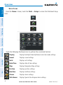
Touch the following icons to perform the associated function:
8
Map
Displays the Navigation Map.
Terrain
Displays the Terrain Map.
HSI/Panel
Displays the Panel Mode.
Nearest
Displays the second-level Nearest Icons.
Traffic
Displays Traffic Page.
Active FPL
Displays the Active Flight Plan.
WPT Info
Displays the Waypoint Information.
Direct To
Displays the 'Direct To' function.
Position
Displays the aircraft's Present Position.
Weather
XM Radio
isplays second-level Weather Icons (aera 510 & 560) or All models
D
with a GDL 39.
Displays XM Radio (aera 510 & 560).
Tools
Displays second-level Tools Icons.
Garmin aera 500 Series Pilot’s Guide
190-01117-02 Rev. C
Overview
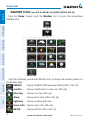
From the ‘Home‘ Screen, touch the Nearest Icon to access the second-level
Nearest Icons.
Overview
NEAREST ICONS
GPS Navigation
Flight Planning
Hazard Avoidance
Touch the following icons to perform the associated function:
Displays nearest airports.
Additional Features
Airport
Airport WX Displays nearest airport weather.
VOR
Displays nearest VORs.
NDB
Displays nearest NDBs.
Displays nearest Visual Reporting Point (VRP) (Atlantic).
User WPT
Displays nearest user waypoints.
City
Displays nearest cities.
ARTCC
Displays nearest ARTCCs.
FSS
Displays nearest Flight Service Stations (FSS).
Airspace
Displays nearest airspace.
190-01117-02 Rev. C
Garmin aera 500 Series Pilot’s Guide
Index
VRP
Appendices
Intersection Displays nearest intersections.
9
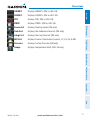
WEATHER ICONS (aera 510 & 560 XM) (ALL MODELS WITH A GDL 39)
From the ‘Home‘ Screen, touch the Weather Icon to access the second-level
Weather Icons.
Touch the following second-level Weather Icons to display the weather product on
the Weather Map:
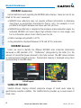
NEXRAD
Displays NEXRAD (NEXt-generation RADar) (XM or GDL 39).
Index
Appendices
Additional Features
Hazard Avoidance
Flight Planning
GPS Navigation
Overview
Overview
Satellite
Displays Satellite Mosaic cloud cover (XM only).
Echo Tops
Displays Echo Tops (XM only).
Winds
Displays Winds Aloft. (XM or GDL 39).
Lightning
Displays Lightning (XM only).
Storm Cells Displays Storm Cells (XM only).
METAR
10
Displays METARs. (XM or GDL 39).
Garmin aera 500 Series Pilot’s Guide
190-01117-02 Rev. C
Overview
Displays SIGMETs. (XM or GDL 39).
TFR
Displays TFRs (XM or GDL 39).
PIREP
Displays PIREPs. (XM or GDL 39).
Freeze Lvl
Displays Freezing Levels (XM only)
Turb Fcst
Displays the Turbulence Forecast (XM only)
Icing Fcst
Displays the Icing Forecast (XM only)
WX Frst
Displays Forecast Information (current, 12, 24, 36, & 48).
Pressure
Displays Surface Pressure (XM only)
Temps
Displays Temperatures Aloft (GDL 39 only).
Flight Planning
SIGMET
GPS Navigation
Displays AIRMETs. (XM or GDL 39).
Overview
AIRMET
Hazard Avoidance
Additional Features
Appendices
Index
190-01117-02 Rev. C
Garmin aera 500 Series Pilot’s Guide
11
TOOLS
From the ‘Home‘ Screen, touch the Tools Icon to access the second-level Tools
Icons.
Appendices
Additional Features
Hazard Avoidance
Flight Planning
GPS Navigation
Overview
Overview
Index
Touch the following second-level icons to perform the associated function:
Setup
Displays third-level Setup Icons.
12
User WPT
Displays User Waypoints and Proximity Waypoints.
Flight Log
Displays Flight Logs.
Track Log
Displays Track Logs.
FPL List
Displays the Flight Plan List.
VNAV
Displays Vertical Navigation.
Garmin aera 500 Series Pilot’s Guide
190-01117-02 Rev. C
Overview
Displays Aircraft Profiles.
E6B Calc
Displays the E6B Calculator.
Weight/Bal
Displays the Weight & Balance.
Data Link
Displays Data Link Information.
Database
Displays database and software version information.
Numbers
Automotive
Displays flight data. (Can be on the Home Screen depending on
options)
Activates automotive mode.
GPS Status
Displays GPS status information.
MP3
Displays Music Player.
Audible
Displays Audible Books.
Overview
Profile
GPS Navigation
Flight Planning
Hazard Avoidance
Additional Features
Appendices
Index
190-01117-02 Rev. C
Garmin aera 500 Series Pilot’s Guide
13
Setup Icons
From the ‘Home‘ Screen, touch the Tools > Setup to access the third-level Setup
Icons.
Additional Features
Hazard Avoidance
Flight Planning
GPS Navigation
Overview
Overview
Index
Appendices
Touch the following third-level icons to perform the associated function:
Display
Displays backlight intensity/timeout and color mode settings.
14
Sound
Displays sound settings.
Units
Displays unit settings.
Date/Time
Displays date & time settings.
Map
Displays Navigation Map settings.
Position
Displays position settings.
Interface
Displays interface settings.
Alarms
Displays alarm settings.
SUA Alarms
Displays Special Use Airspace alarm settings.
Garmin aera 500 Series Pilot’s Guide
190-01117-02 Rev. C
Overview
Displays Data Link setup information.
Weather
Displays Weather setup information (510 and 560 Models only).
Power
Displays power settings
Keyboard
Displays keyboard layout settings.
Overview
Data Link
GPS Navigation
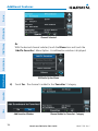
SELECTING A FUNCTION
Selecting a function:
Touch the desired icon. The icon will momentarily turn blue when selected.
Flight Planning
Hazard Avoidance
Terrain Icon Selected (‘Home’ Screen)
Additional Features
SCROLLING
Scrolling up/down on the touchscreen:
T ouch the Up or Down Arrow Icons (if available).
Or:
If the arrow icons are present, touch and drag your finger up or down.
Appendices
Index
Scrolling (Weather Icons)
190-01117-02 Rev. C
Garmin aera 500 Series Pilot’s Guide
15
GPS Navigation
Overview
Overview
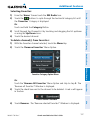
1.4 ACCESSING SYSTEM FUNCTIONALITY
OPTION MENUS
The aera has a dedicated Menu Icon that displays a context-sensitive list of options
for the function displayed.
The Option Menu allows the user to access additional features or make setting
changes which specifically relate to the currently displayed function.
Navigating the option menu:
If available, touch the Menu or Menu/
Additional Features
Appendices
Index
Icon
Touch the Up/Down Icons if necessary to scroll through the Option Menu.
Touch the desired menu option.
Hazard Avoidance
Flight Planning
➊
➋
➌
➊
➌
➋
DATA ENTRY
Alphanumeric data can be entered using the keypad. In some instances, such as
when entering an identifier, the aera tries to predict the desired identifier based on the
characters being entered. In this case, if the desired identifier appears, use the OK Icon
to confirm the entry without entering the rest of the identifier manually. This can save
the pilot from having to enter all the characters of the identifier.
Predetermined data options are entered by touching the
to cycle through a
horizontal list, or by touching the button to display a vertical list (if only two options
are available, touching the button will toggle the two data options).
Besides character-by-character data entry using the keypad and predetermined
data entry, the aera also provides a shortcut for entering ‘Flight Plan’, ‘Nearest’, and
‘Recent’ waypoint identifiers.
16
Garmin aera 500 Series Pilot’s Guide
190-01117-02 Rev. C
Overview
Entering alphanumeric data:
When alphanumeric data can be entered, a keypad will appear after
touching the desired button.
➋
➌
Touch the keypad to enter the desired data.
GPS Navigation
Touch OK.
➊
➌
➋
Numeric data may also be entered using
applicable).
Flight Planning
Overview
➊
or '+/-' buttons (if
Hazard Avoidance
Entering predetermined data options:
➊
Touch the Data Option Button to display a vertical list of data options (if
applicable), or to toggle two data options (i.e., On/Off).
Touch the
buttons to cycle through a horizontal list (if more than two
data options are available).
➋
If using the vertical list, touch the desired data option from the list.
Additional Features
Or:
Appendices
➋
➊
Data Option Button
Index
190-01117-02 Rev. C
Garmin aera 500 Series Pilot’s Guide
17
Overview
Overview
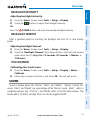
WAYPOINT INFORMATION TABS
Waypoint information is broken down into 5 tabs (Info, Freq, Runway, WX (aera
510 & 560 only), and AOPA (aera 550 & 560 Americas only)).
GPS Navigation
Waypoint Information Tabs:
➊
➋
From the 'Home' Screen, touch the WPT Info Icon.
Touch the desired Tab (Info, Freq, Runway, WX/NOTAM (optional),
AOPA (optional)).
➋
1.5 USING MAP DISPLAYS
NOTE: Refer to the GPS Navigation section for more information on Map
Display Setup.
Map displays are used extensively in the aera to provide situational awareness in
flight. Most aera maps can display the following information:
•Airports, NAVAIDs, airspaces, airways, land data (highways, cities, lakes, rivers,
borders, etc.) with names
•Map Pointer information (distance and bearing to pointer, location of pointer,
name, and other pertinent information)
Appendices
Additional Features
Hazard Avoidance
Flight Planning
➊
•Map range
•Aircraft icon (representing present position)
Index
•Flight plan legs
•User waypoints
•Track vector
•Topography data
18
Garmin aera 500 Series Pilot’s Guide
190-01117-02 Rev. C
Overview
Adjusting the map range:
While viewing a Map Display, touch the In or Out Icons.
Flight Planning
Range
Icons
GPS Navigation
There are 23 different map ranges available, from 200 feet to 800 nm. The current
map range is indicated in the lower right. The scale bar represents the map scale. To
change the map range on any map, use the Out or In Icons to zoom ‘out’ (increasing),
or zoom ‘in‘ (decreasing).
Overview
MAP RANGE
Navigation Map
Scale Bar Representing a Map
Scale of 3 nm Per
Scale Width.
Additional Features
When the selected range exceeds the resolution of the map data, ‘overzoom’ appears
below the map range scale.
Hazard Avoidance
Map Range
Map Range/Overzoom
Auto Zoom allows the aera to change the map display range to the smallest range
clearly showing the active waypoint. Auto Zoom can be overridden by adjusting the
range and remains that way until the active waypoint changes, a terrain or traffic alert
occurs, or the aircraft takes off.
Index
Enabling/disabling auto zoom:
1) From the 'Home' Screen, touch Map > Menu > Set Up Map.
2) Touch the
buttons to select the 'General' Category.
190-01117-02 Rev. C
Garmin aera 500 Series Pilot’s Guide
Appendices
AUTO ZOOM
19
Overview
Overview
3) Touch 'Autozoom'.
4) Touch the 'On/Off' Data Option Button.
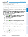
MAP PANNING
GPS Navigation
Map panning allows the pilot to:
•View parts of the map outside the displayed range without adjusting the map
range
•Highlight and select locations on the map
•Designate locations for use in flight planning
•View airspace and airway information
When the panning function is selected by touching anywhere on the Map, the Map
Pointer is displayed. An Information Window also appears at the bottom of the map
display showing the the bearing, distance and time to the pointer from the aircraft’s
present position, the elevation of the land at the position of the pointer, or the object’s
(airports, obstacles, etc) elevation, if known.
When the Map Pointer is over a map feature, the map feature is highlighted, an
information box appears on the map, and the highlighted map feature is displayed
on the Map Feature Button at the bottom of the screen (even if the name was not
originally displayed on the map).
Touching the Map Feature Button displays additional information for the
highlighted map feature. If multiple features are present at the Map Pointer position,
green arrows will appear on the Map Feature Button. Touching the
will cycle
through the list of map features present at that position.
Activating the map pointer:
While viewing a Map Display, touch anywhere on the map to activate the
map pointer. Touch the Cancel Icon to remove the map pointer.
Panning the map:
While viewing a Map Display, touch anywhere on the map and drag. Touch
the Cancel icon to remove the map pointer.
Index
Appendices
Additional Features
Hazard Avoidance
Flight Planning
•Review information for a selected airport, NAVAID or user waypoint
20
Garmin aera 500 Series Pilot’s Guide
190-01117-02 Rev. C
Overview
Map Pointer
Overview
Information
Box
Map Panning (Navigation Map)
Hazard Avoidance
➊
➋
Additional Features
➍
➌
While viewing a Map Display, touch anywhere on the map to activate the
map pointer. When the Map Pointer is over a map feature, the map feature
is highlighted, an information box appears on the map, and the highlighted
map feature is displayed on the Map Feature Button at the bottom of the
screen. If multiple features are present at the Map Pointer position, green
arrows will appear on the Map Feature Button.
➋
If necessary, touch the
buttons to cycle through the list of map
features present at that position.
Garmin aera 500 Series Pilot’s Guide
21
Index
➊
Appendices
Reviewing information for a map feature:
190-01117-02 Rev. C
Flight Planning
Green Arrow
Indicating
Multiple
Features are
Present at the
Map Pointer
Location.
- Bearing,
Distance, and
Time En Route
to the Pointer
from the Aircraft's Present
Position.
- Elevation
at the Pointer
location.
GPS Navigation
Map Feature
Button
Overview
Touch the Map Feature Button to review information for the Map Feature.
Touch the Back Icon to return to the map or touch and hold the Menu/
Icon to navigate to the map feature. Touch the Cancel Icon to remove the
map pointer.
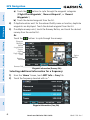
MAP OVERLAYS
The ➊Weather, ➋Topography, ➌Terrain, and ➍Satellite Imagery map overlays
can be displayed or removed.
➊
➋
➌
➍
Displaying/removing map overlays:
1) From the 'Home' Screen, touch Map > Menu > Show/Hide.
2) Touch the 'Show/Hide' Data Option Button for the desired overlay.
Satellite View only displays satellite imagery at and above the 20nm range. Below
the 20nm range, 'no sat view' is displayed below the map range.
Index
Appendices
Additional Features
Hazard Avoidance
Flight Planning
GPS Navigation
Overview
➌
➍
22
Garmin aera 500 Series Pilot’s Guide
190-01117-02 Rev. C
Overview
Overview
MAP SYMBOLS
Refer to Appendix H for a list of map symbols.
DECLUTTER
Flight Planning
Adjusting the declutter level of the navigation map:
1) From the 'Home' Screen, touch Map > Menu > Declutter.
2) Touch the desired level (-1, -2, -3) on the right side of the screen. The
currently selected level is highlighted blue.
3) Touch the Back Icon to remove the detail options.
GPS Navigation
The map can be adjusted to declutter (remove unwanted items, such as highways)
on the map.
Hazard Avoidance
Declutter
The map detail can also be adjusted. Map detail changes the amount of detail with
respect to the zoom scale.
Appendices
Adjusting the map detail:
1) From the 'Home' Screen, touch Map > Menu > Set Up Map.
2) Touch the
buttons to select the 'General' Category.
Additional Features
MAP DETAIL
3) Touch Detail Level.
4) Touch the Data Option Button, and touch the desired option from the list
(Least, Less, Normal, More, or Most).
Index
190-01117-02 Rev. C
Garmin aera 500 Series Pilot’s Guide
23
1.6 SYSTEM SETTINGS
The third-level Setup Icons allow management of the following system parameters:
Flight Planning
GPS Navigation
Overview
Overview
•Display
•Alarms
•Sound
•SUA Alarms
•Units
•Data Link
•Date & Time
•Weather
•Map
•Power
•Position
•Keyboard
•Interface
Additional Features
Hazard Avoidance
Restoring system setting defaults:
1) From the 'Home' Screen, touch Tools > Setup.
2) Touch the desired Setup Icon (Display, Sound, Units, Date & Time,
Map, Position, Interface, Alarms, SUA Alarms, or Power).
3) Touch Menu > Restore Default.
Or:
From the 'Home' Screen, touch Tools > Setup > Menu > Restore All
Settings.
Index
Appendices
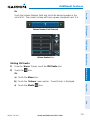
DISPLAY
Display Setup
24
Garmin aera 500 Series Pilot’s Guide
190-01117-02 Rev. C
Overview
Overview
BACKLIGHT INTENSITY
Press the
GPS Navigation
Adjusting backlight intensity:
1) From the 'Home' Screen, touch Tools > Setup > Display.
2) Touch the
buttons to adjust the backlight intensity.
Or:
POWER Button and enter the desired backlight intensity.
BACKLIGHT TIMEOUT
TOUCHSCREEN
Additional Features
Calibrating the touchscreen:
1) From the 'Home' Screen, touch Tools > Setup > Display > Menu >
Calibrate.
2) Follow the onscreen instructions, and touch OK. The unit will restart.
Hazard Avoidance
Adjusting backlight timeout:
1) From the 'Home' Screen, touch Tools > Setup > Display.
2) Touch the 'Backlight Timeout' Data Option Button, and touch the desired
option from the list (Stays On, 15 Seconds, 30 Seconds, 1 Minute, or
2 Minutes).
Flight Planning
After a specified period of inactivity the backlight will turn off to save battery
power.
SOUND
Appendices
Sound is broken down into ‘Master’, ‘Alerts’, and ‘Media’. 'Master’ controls ALL
sound. ‘Alerts’ and ‘Media’ are a percentage of the ‘Master’ sound. ‘Alerts’ refers to
navigation phrases (e.g. "Pull Up"), and ‘Media’ refers to the XM radio volume. The
Terrain Alerts, TIS Alerts, and Key Tones can also be toggled On/Off.
Index
190-01117-02 Rev. C
Garmin aera 500 Series Pilot’s Guide
25
GPS Navigation
Overview
Overview
Flight Planning
Adjusting the sound:
1) From the 'Home' Screen, touch Tools > Setup > Sound.
Or:
Hazard Avoidance
Sound Setup
T ouch the
Icon to mute the Master, Alerts, or Media audio. A blue
'X' will appear over the icon.
Or:
T ouch the 'On/Off' Data Option Button to toggle Terrain Audio, TIS Audio,
or Key Tones on or off.
Additional Features
2) Touch the
buttons to adjust the sound.
Or:
1) Press the
POWER Button to quickly access the Master volume/mute.
2) Touch Menu > Sound Setup to access ALL volume settings.
Muting sound:
Appendices
See the ‘Adjusting the Sound’ procedure above.
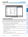
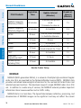
ADDITIONAL SETTINGS
Index
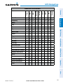
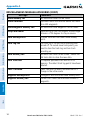
Changing settings (Units, Date & Time, Position, Interface, Alarms,
SUA Alarms, and Power):
1) From the 'Home' Screen, touch Tools > Setup.
2) Touch the desired Settings Icon (Units, Date/Time, Position, Interface,
Alarms, SUA Alarms, or Power).
26
Garmin aera 500 Series Pilot’s Guide
190-01117-02 Rev. C
Overview
GPS Navigation
4) Touch and hold the Back Icon to return to the ‘Home’ Screen.
Overview
3) Touch the desired setting to change. If only two options are available,
touching the field will toggle the two settings. If more than two options are
available, a vertical list is displayed with a blue outline around the current
setting. Touch the '+' or '-' buttons to increase/decrease the numerical
values (if necessary).
Icon
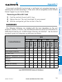
Display
Sound
Flight Planning
Available Settings
Backlight Intensity, Backlight Timeout, Color Mode, Screenshot
Master (0-10), Alerts (0-10), Media (0-10), Key Tone, Terrain Audio,
TIS-A Audio
Units
Distance, Speed, Direction Display, Temperature, Altitude, Vertical
Speed, Pressure, Fluid Volume
Date/Time Time Format, Auto UTC Offset
Map
All available map settings
Position
Location Format, Map Datum, Heading, Magnetic Variation
Interface
Serial Data Format
Alarms
Arrival, Next WPT, Proximity, Fuel Tank Reminder
SUA Alarms Class B/TMA, Class C/TCA, Class D, Restricted, MOA, Other/ADIZ,
Parachute Area
Data Link
Aircraft type, ADS-B Traffic Data Status
Weather
Weather Data Source
Power
Power Loss Warning
Keyboard
Keyboard layout settings
Hazard Avoidance
Additional Features
Appendices
Index
190-01117-02 Rev. C
Garmin aera 500 Series Pilot’s Guide
27
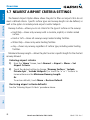
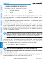
1.7 NEAREST AIRPORT CRITERIA SETTINGS
The Nearest Airports Option Menu allows the pilot to filter out airports that do not
meet a defined criteria. Specific surface types and runway lengths can be defined, as
well as the option to include private airports and/or heliports.
GPS Navigation
Overview
Overview
Runway Surface—allows you to set criteria for the type of surface on the runway:
• Hard Only—shows only runways with a concrete, asphalt, or similar sealed
surface.
• Water Only—shows only water landing facilities.
• Any—shows any runway, regardless of surface type, including water landing
facilities.
Minimum Runway Length—allows the pilot to enter a specific length for the shortest
runway allowed.
Entering airport criteria:
1) From the 'Home' Screen, touch Nearest > Airport > Menu > Set
Airport Criteria.
2) Touch the desired setting to change ('Runway Surface', 'Include
Private Apts', 'Include Heliports') or touch the '+' or '-' buttons to
increase/decrease the Minimum Runway Length.
Or:
To restore defaults, touch Menu > Restore Default.
Additional Features
Hazard Avoidance
Flight Planning
• Hard or Soft—shows all runways except water landing facilities.
Index
Appendices
Restoring airport criteria defaults:
See the ‘Entering Airport Criteria’ procedure above.
28
Garmin aera 500 Series Pilot’s Guide
190-01117-02 Rev. C
Overview
Overview
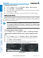
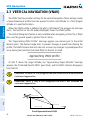
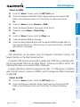
1.8 PRESENT POSITION
POSITION
GPS Navigation
The Present Position function displays latitude, longitude, GPS altitude, reference
waypoint, type, distance, direction, and bearing. The reference waypoint is designed to
display the current position in relation to a prominent landmark. The pilot can change
the reference waypoint ‘Nearest Type’ using the ‘Change Nearest Type’ menu option.
By default the Nearest Type is set to ‘Automatic’, which will display the nearest large
airport, enroute VOR, or city (in that order).
Flight Planning
Hazard Avoidance
Present Position
Additional Features
Changing the Nearest Type:
1) From the 'Home' Screen, touch Position > Menu > Change Nearest
Type.
2) Touch the desired nearest type ('Automatic', 'Airport', 'VOR', 'NDB',
'Intersection', 'City', or 'Waypoint').
Appendices
Viewing the present position:
From the 'Home' Screen, touch Position.
NEW LOCATION
190-01117-02 Rev. C
Garmin aera 500 Series Pilot’s Guide
29
Index
The ‘New Location’ menu option is used when the GPS Receiver is having trouble
finding the satellites it expects to be there.
Overview
SIMULATOR MODE
Simulator Mode is helpful for practicing with the unit indoors or when no satellite
or XM signals are available. All waypoints and routes created in Simulator Mode are
retained in memory for future use.
Hazard Avoidance
Flight Planning
GPS Navigation
Overview
Entering a new location:
1) From the 'Home' Screen, touch Position > Menu > New Location.
2) Touch 'Use Map', or 'Use Identifier'.
3) After selecting your approximate position using the map pointer or entering
an identifier, touch OK.
4) The GPS Receiver will begin a new search based on the location entered.
NOTE: Do not attempt to navigate using Simulator Mode. When the unit is
set to Simulator Mode, the GPS receiver is turned off. Any Satellite Signal
Strength Bars shown are only simulations and do not represent the strength
of actual satellite signals.
Additional Features
Starting/Stopping Simulator Mode:
From the 'Home' Screen, touch Position > Menu > Start/Stop Simulator.
Index
Appendices
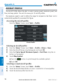
Adjusting the simulated altitude, track, speed, waypoint, & position:
1) From the 'Home' Screen, touch Position > Menu > Start Simulator.
2) Touch the 'GPS simulator is on (for use indoors)' message to remove it.
3) Touch Menu > Drive Simulator.
4) Enter the desired data by touching the fields or using the +/- buttons.
Refer to Section 1.4 'Data Entry' for more information.
Simulator Mode
30
Garmin aera 500 Series Pilot’s Guide
190-01117-02 Rev. C
GPS Navigation
SECTION 2 GPS NAVIGATION
Overview
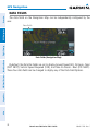
2.1 INTRODUCTION
Flight Planning
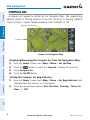
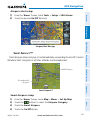
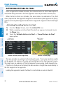
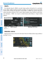
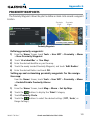
An aircraft icon is placed on the Navigation Map at the location corresponding
to the calculated present position. The aircraft position and the flight plan legs are
accurately based on GPS calculations. The basemap upon which these are placed are
from a source with less resolution, therefore the relative position of the aircraft to map
features is not exact. The leg of the active flight plan currently being flown is shown as
a magenta line on the navigation map. The other legs are shown in white.
GPS Navigation
The Navigation Map displays aviation data (e.g., airports, VORs, airways, airspaces),
geographic data (e.g., cities, lakes, highways, borders), and topographic data (map
shading indicating elevation). The Navigation Map can be oriented three different
ways: North Up (NORTH UP), Track Up (TRK UP) or Desired Track Up (DTK UP).
Hazard Avoidance
Additional Features
Inactive Leg
(White)
Active Leg
(Magenta)
Appendices
Aircraft Icon
Flight Plan Legs (Navigation Map)
Index
190-01117-02 Rev. C
Garmin aera 500 Series Pilot’s Guide
31
GPS Navigation
Overview
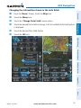
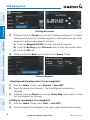
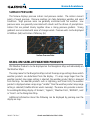
DATA FIELDS
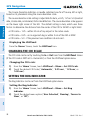
The data fields on the Navigation Map can be independently configured by the
user.
Data Fields (Navigation Map)
By default, the Data Bar Fields are set to display Ground Speed (GS), Distance - Next
(DIST NEXT), Vertical Speed Required (VSR), and Time En Route - Next (ETE NEXT).
These four data fields can be changed to display any of the Data Field Options.
Index
Appendices
Additional Features
Hazard Avoidance
Flight Planning
GPS Navigation
Data Fields
32
Garmin aera 500 Series Pilot’s Guide
190-01117-02 Rev. C
GPS Navigation
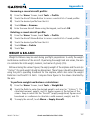
Changing the information shown in the data fields:
Touch the Menu Icon.
Touch the 'Change Data Fields' menu option.
Touch the desired Data Field to change. A list of available Data Field Options
is displayed.
Touch the desired Data Field Option.
Touch the OK Icon.
Flight Planning
➊
➋
Hazard Avoidance
➍
➌
Additional Features
➎
GPS Navigation
➎
➏
From the ‘Home’ Screen, touch the Map Icon.
Overview
➊
➋
➌
➍
➏
Appendices
Index
190-01117-02 Rev. C
Garmin aera 500 Series Pilot’s Guide
33
GPS Navigation
GPS Navigation
Overview
DATA FIELD OPTIONS
•Accuracy
•Sunrise
•Altitude
•Sunset
•Bearing (BRG)
•Course to Steer (CTS)
•Time En Route (Destination) (ETE
DEST)
•Crosstrack Error (XTK)
•Time En Route (Next) (ETE NEXT)
•Desired Track (DTK)
•Time of Arrival (Destination) (ETA
DEST)
•Distance (Destination) (DIST DEST)
Flight Planning
•Distance (Next) (DIST NEXT)
•En Route Safe Altitude (ESA)
•External Voltage (EXT VOLTS)
Hazard Avoidance
•Flight Timer (FLT TIMER)
•Fuel Timer
•Glide Ratio (G/R)
•Ground Speed (GS)
Additional Features
•Ground Track (TRK)
•Minimum Safe Altitude (MSA)
•Time to VNAV (VNAV TIME)
•Time (Local)
•Time (UTC)
•Vertical Speed (VS)
•Vertical Speed Required (VSR)
•Wx (Altimeter) (WX ALTIM)
•Wx (Dew Point) (WX DEW PT)
•Wx (Rel. Humidity) (WX HUMIDITY)
•Wx (Temperature) (WX TEMP)
•Wx (Wind) (WX WIND)
Index
Appendices
•Next Waypoint (NEXT WPT)
•Time of Arrival (NEXT) (ETA NEXT)
34
Garmin aera 500 Series Pilot’s Guide
190-01117-02 Rev. C
GPS Navigation
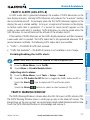
NUMERIC FLIGHT DATA
NOTE: For units that support XM and have a GDL 39, the 'Numbers' icon is
moved to the Tools Page.
GPS Navigation
Accessing numeric flight data:
From the 'Home' Screen, touch Numbers.
Overview
The numeric flight data can be independently configured by the user.
Flight Planning
Changing numeric flight data fields:
1) From the 'Home' Screen, touch Numbers.
2) Touch the desired data field to change. The available data fields are
displayed.
3) Touch the desired data field.
4) Touch OK.
Hazard Avoidance
Restoring default numeric flight data:
From the 'Home' Screen, touch Numbers > Menu > Restore Default.
Additional Features
Numeric Flight Data
Appendices
Index
190-01117-02 Rev. C
Garmin aera 500 Series Pilot’s Guide
35
GPS Navigation
Overview
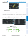
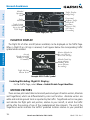
COMPASS ARC
A compass arc appears by default on the Navigation Map. The magenta bug
indicator (similar to the bug indicator on the HSI) can be set to ‘Bearing’ (default),
‘Course to Steer’, a specific heading reference (‘User Selected’), or ‘Off’.
GPS Navigation
Magenta Bug Indicator
Flight Planning
Compass Arc
Hazard Avoidance
Compass Arc (Navigation Map)
Additional Features
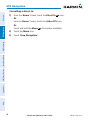
Displaying/Removing the Compass Arc from the Navigation Map:
1) From the 'Home' Screen, touch Map > Menu > Set Up Map
2) Touch the
buttons to select the 'General' Category (if necessary).
3) Touch Compass Arc.
4) Touch the On/Off Button.
Index
Appendices
Setting the Compass Arc Bug Indicator:
1) From the 'Home' Screen, touch Map > Menu > Set Bug Indicator (only
available when the compass arc is displayed).
2) Touch the desired menu option ('User Selected', 'Bearing', 'Course to
Steer', or 'Off').
36
Garmin aera 500 Series Pilot’s Guide
190-01117-02 Rev. C
GPS Navigation
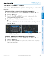
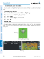
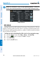
2.2 HSI/PANEL
- Next Waypoint
-Distance
Altitude
Ground Speed
Flight Planning
CDI Scale
Adjustment
Option
Menu
Turn Rate Indicator
HSI/Panel
CDI Scale
Hazard Avoidance
Estimated Time Enroute
GPS Navigation
HSI
Overview
The HSI/Panel shows GPS-derived data in a graphical format. Keep in mind the
differences between the GPS-derived panel and mechanical instruments, as mechanical
panel instruments use sensors that provide information different from that derived
using GPS.
Vertical Speed
The graphic HSI depicts the course to the destination or the next waypoint in a flight
plan, current ground track, off course error, and a To/From indication. The rotating
compass indicates your current ground track.
Bearing is the compass direction from the present position to a destination waypoint.
Course to Steer is the recommended direction to steer in order to reduce cross-track
error and return to the course line.
Appendices
The course pointer and course deviation needle indicate the course and whether you
are on the course. The Bug Indicator can be set to ‘Bearing’ (default), ‘Course to Steer’,
a specific heading reference (‘User Selected’), or ‘Off’.
Additional Features
The Panel shows a graphic Horizontal Situation Indicator (HSI) surrounded by
additional indicators.
Index
190-01117-02 Rev. C
Garmin aera 500 Series Pilot’s Guide
37
The Course Deviation Indicator, or needle, indicates how far off course, left or right,
based on its placement along the course deviation scale.
The course deviation scale setting is adjustable for Auto, ±0.25, 1.25 or 5.0 (nautical
mile, statute mile, or kilometer) full-scale deflection. The course deviation scale appears
on the lower right corner of the HSI. The default setting is Auto, which uses three
factors to determine the distance from the center of the CDI to full left or right limits:
•CDI scale = 1.25 - within 30 nm of any airport in the active route.
•CDI scale = 0.25 - on an approach leg or within 2 nm of the FAF or MAP.
•CDI scale = 5.0 - if the previous two conditions do not exist.
Displaying the HSI/Panel:
From the 'Home' Screen, touch the HSI/Panel Icon.
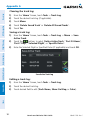
CHANGING THE CDI SCALE
The CDI scale can be set by touching the In or Out Icons from the HSI/Panel Screen
(if the CDI scale is NOT set to 'Automatic') or from the HSI/Panel option menu.
Changing the CDI scale:
1) From the 'Home' Screen, touch HSI/Panel > Menu > Set CDI Scale.
2) Touch the desired CDI Scale (' Automatic', ' 0.25 nm', ' 1.25 nm', or
'5.00 nm').
Additional Features
Hazard Avoidance
Flight Planning
GPS Navigation
Overview
GPS Navigation
SETTING THE BUG INDICATOR
The Bug Indicator can be set from the HSI/Panel option menu.
Index
Appendices
Setting the Bug Indicator:
1) From the 'Home' Screen, touch HSI/Panel > Menu > Set Bug
Indicator.
2) Touch the desired menu option ('User Selected', 'Bearing', 'Course to
Steer', or 'Off').
38
Garmin aera 500 Series Pilot’s Guide
190-01117-02 Rev. C
GPS Navigation
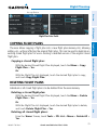
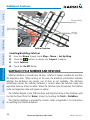
MANUALLY SETTING A COURSE
GPS Navigation
Manually setting a course to the destination waypoint:
1) From the ‘Home’ Screen, touch the HSI/Panel or the Active FPL Icon.
2) Touch the Menu Icon
3) Touch the ' Set OBS and Hold' menu option (only available when
navigating a Direct To or Flight Plan).
4) Touch the '+' or '-' Buttons to increase/decrease the value
Or:
Touch the Radial Button to enter the desired radial using the keypad and
touch the OK Icon.
Overview
Use the ‘Set OBS and Hold’ menu option to manually set your course to the
destination.
Flight Planning
Hazard Avoidance
Set OBS
Radial Button
Appendices
Returning to automatic sequencing of route waypoints:
1) From the ‘Home’ Screen, touch the HSI/Panel or the Active FPL Icon.
2) Touch the Menu Icon
3) Touch the 'Release Hold' menu option (only available when navigating a
Direct To or Flight Plan).
Additional Features
HSI/Panel Option Menu
Index
190-01117-02 Rev. C
Garmin aera 500 Series Pilot’s Guide
39
GPS Navigation
The VNAV function provides settings for the vertical navigation. These settings create
a three-dimensional profile from the present location and altitude to a final (target)
altitude at a specified location.
When the VNAV profile is defined, the pilot is informed of the progress by message
alerts. The teal bar on the HSI (when displayed) shows the VNAV profile.
The Vertical Navigation feature is only available when navigating a Direct To or flight
plan, and the ground speed is greater than 35 knots.
The “Approaching VNAV Profile” message appears one minute prior to the initial
descent point. The descent angle locks to prevent changes in speed from altering the
profile. The VNAV feature does not take into account any changes in groundspeed that
occur during the transition from level flight to descent or climb.
At 500 ft above the target altitude, the “Approaching Target Altitude” message
appears, the ‘Estimated Time To VNAV’ goes blank, and the VNAV indicator disappears
from the HSI.
CAUTION: The aera is a VFR navigation tool and should not be used to perform
instrument approaches.
CAUTION: VNAV is only a VFR navigation aid and is not intended for
instrument approaches.
AV
VN
Appendices
Additional Features
Hazard Avoidance
Flight Planning
GPS Navigation
Overview
2.3 VERTICAL NAVIGATION (VNAV)
Pr
ile
of
Distance to Profile
Glid
eR
to T
arg
et
Index
atio
Target Altitude
Distance to Target
Airport
Visual Representation of VNAV
40
Garmin aera 500 Series Pilot’s Guide
190-01117-02 Rev. C
GPS Navigation
USING THE VNAV FEATURE
Overview
Enabling/disabling the VNAV indicator:
1) From the ‘Home’ Screen, touch the HSI/Panel Icon.
2) Touch the Menu Icon
3) Touch the 'Enable VNAV Indicator' or 'Disable VNAV Indicator' menu
option (only available when navigating a Direct To or Flight Plan).
GPS Navigation
Hazard Avoidance
Capturing/cancelling VNAV profile:
1) Enter a valid VNAV profile (see 'Configuring a VNAV Profile' below) and
begin navigation.
2) From the ‘Home’ Screen, touch the HSI/Panel Icon.
3) Touch the 'Capture VNAV Profile' or 'Cancel Capture' menu option
(only available when navigating a Direct To or Flight Plan).
Flight Planning
Use the VNAV (Vertical Navigation) feature to ensure the aircraft is at the proper
altitude. The VNAV Indicator appears on the HSI (when displayed) as a horizontal teal
bar. A message appears when approaching the VNAV Profile. When the bar is in the
vertical center of the HSI, the aircraft is at the proper altitude for the VNAV Profile.
VNAV Indicator
Additional Features
Appendices
VNAV Indicator (Panel)
Index
190-01117-02 Rev. C
Garmin aera 500 Series Pilot’s Guide
41
GPS Navigation
Flight Planning
GPS Navigation
Overview
Configuring a VNAV profile:
1) From the 'Home' Screen, touch Tools > VNAV
2) Touch the desired fields ('Profile', 'Altitude', etc) to enter the VNAV
profile.
3) Touch and hold the Back Icon to return to the ‘Home’ Screen.
Vertical Navigation
Hazard Avoidance
• Waypoint—Enter any waypoint along the currently active route as the
reference waypoint. The reference waypoint defines the target location.
• Profile—Enter the descent rate.
• Altitude—Enter the desired reference waypoint altitude. Select ‘Above
Additional Features
Waypoint’ to use field elevation for airports in the Jeppesen database or ‘MSL’
to specify an exact MSL altitude target.
• By—Enter the target location with settings of distance ‘Before’ or ‘After’ a
reference waypoint. To set a target location at a reference waypoint, enter a
distance of zero.
Index
Appendices
• VNAV Messages—Select ‘On’ or ‘Off’ to enable/disable VNAV alert messages.
42
Garmin aera 500 Series Pilot’s Guide
190-01117-02 Rev. C
GPS Navigation
2.4 MAP DISPLAY SETUP
•Map Pointer information (distance and bearing to pointer, location of pointer,
name, and other pertinent information)
•Map range
Flight Planning
•Aircraft icon (representing present position)
GPS Navigation
•Airports, NAVAIDs, airspaces, airways, land data (highways, cities, lakes, rivers,
borders, etc.) with names
Overview
Map displays are used extensively in the aera to provide situational awareness in
flight. Most aera maps can display the following information:
•Flight plan legs
•User waypoints
•Topography data
MAP ORIENTATION
•North Up aligns the top of the map display to north (default setting).
Additional Features
Maps are shown in one of three different orientation options, allowing flexibility
in determining aircraft position relative to other items on the map (North Up) or for
determining where map items are relative to where the aircraft is going (Track Up), or
desired track up (DTK UP)).
Hazard Avoidance
•Track vector
•Track Up aligns the top of the map display to the current ground track.
Appendices
•Desired Track (DTK) Up aligns the top of the map display to the desired course.
Index
190-01117-02 Rev. C
Garmin aera 500 Series Pilot’s Guide
43
GPS Navigation
Overview
NOTE: Map orientation can only be changed from the Navigation Map Option
Menu. All other maps (except weather maps) that show navigation data
reflect the orientation selected for the Navigation Map.
GPS Navigation
Changing the Navigation Map orientation:
1) From the 'Home' Screen, touch Map > Menu > Set Up Map
2) Touch the
buttons to select the 'General' Category (if necessary).
3) Touch Orientation.
4) Touch the
buttons to select 'North Up', 'Track Up', or 'DTK Up'.
Flight Planning
AIRPORTS, NAVAIDS, CITIES & ROADS
Appendices
Additional Features
Hazard Avoidance
Setting up and customizing airports, NAVAIDs, cities & roads for
the navigation map:
1) From the 'Home' Screen, touch Map > Menu > Set Up Map
2) Touch the
buttons to select the 'Airport', 'Navaid', 'City', or 'Road'
Category.
3) Touch the
buttons to select the desired settings, or touch the Data
Option Button to toggle the option On/Off.
Map Setup (Airport Category Example)
Data Option Button
Index
Runway
Extension
Runway
Number
Runway Extensions and Numbers
44
Garmin aera 500 Series Pilot’s Guide
190-01117-02 Rev. C
GPS Navigation
AIRWAYS
Additional Features
Displaying/removing airways:
1) From the 'Home' Screen, touch Map > Menu > Set Up Map
2) Touch the
buttons to select the 'Navaid' Category.
3) Touch Airways.
4) Touch the
buttons to select the desired setting ('Off', 'Low', 'High',
or 'Both').
Hazard Avoidance
When airways are selected for display on the map, the airway waypoints (VORs,
NDBs and Intersections) are also displayed.
Flight Planning
Low Altitude Airways are drawn in gray. High Altitude Airways are drawn in green.
When both types of airways are displayed, high altitude airways are drawn on top of
Low Altitude Airways.
GPS Navigation
High Altitude Airways (or Jet Routes) primarily serve airliners, jets, turboprops, and
turbocharged piston aircraft operating above 18,000 feet MSL. Jet Routes start at
18,000 feet MSL and extend upward to 45,000 feet MSL (altitudes above 18,000 feet
are called “flight levels” and are described as FL450 for 45,000 feet MSL). Jet Routes
are designated with a “J” before the route number.
Overview
Low Altitude Airways (or Victor Airways) primarily serve smaller piston-engine,
propeller-driven airplanes on shorter routes and at lower altitudes. Airways are eight
nautical miles wide and start 1,200 feet above ground level (AGL) and extend up
to but not including 18,000 feet mean sea level (MSL). Low Altitude Airways are
designated with a “V” before the airway number (hence the name “Victor Airways”)
since they run primarily between VORs.
Appendices
Index
Airways
190-01117-02 Rev. C
Garmin aera 500 Series Pilot’s Guide
45
GPS Navigation
The WPT INFO (Waypoint Information) function provides airport and waypoint
information.
Waypoints are predetermined geographical positions (internal database) or pilotentered positions, and are used for all phases of flight planning and navigation.
Waypoints can be selected by entering the ICAO identifier, entering the name of
the facility, or by entering the city name. As a waypoint identifier, facility name, or
location is entered, the aera’s Spell’N’Find™ feature scrolls through the database,
displaying those waypoints matching the characters which have been entered up to
that point. A direct-to navigation leg to the selected waypoint can be initiated by
pressing the Menu/ Icon.
The waypoint function allows the pilot to review airport information, runway
information, frequencies, AOPA information (if available), and weather information
(if available) by touching the desired tab. The pilot can manually enter the identifier
or the aera will choose the most appropriate identifier based on the current position
and phase of flight.
-Waypoint Identifier/Symbol/Type
-Facility Name
-City/State
-Fuel Available
-Elevation
Time Zone (UTC Offset)
-Region
Additional Features
Hazard Avoidance
Flight Planning
GPS Navigation
Overview
2.5 WAYPOINTS
Appendices
Waypoint
Identifier
Button
Option
Menu
Bearing/
Distance
Info Tab
Index
Waypoint Information (Info Tab)
46
Garmin aera 500 Series Pilot’s Guide
Lat/Long
190-01117-02 Rev. C
GPS Navigation
The following descriptions and abbreviations are used:
Overview
•Usage type: Public, Military, or Private
•Runway surface type: Hard, Turf, Sealed, Gravel, Dirt, Soft, Unknown, or Water
•COM Availability: TX (transmit only), RX (receive only), PT (part time), * (additional
information available)
Appendices
Index
Garmin aera 500 Series Pilot’s Guide
Additional Features
190-01117-02 Rev. C
Hazard Avoidance
Selecting a runway:
1) From the 'Home' Screen, touch WPT Info > Runway Tab.
2) Touch the Waypoint Identifier Button.
3) Enter the desired waypoint:
a) Touch the
buttons to 'Search by Identifier', 'Search by
Facility Name', or 'Search by City' using the keypad.
b) Enter the desired waypoint.
c) Touch the OK Icon.
Or:
Flight Planning
Selecting an airport for review by identifier, facility name, or city:
1) From the 'Home' Screen, touch WPT Info > Info Tab (if necessary).
2) Touch the Waypoint Identifier Button.
3) Enter the desired waypoint:
a) Touch the
buttons to 'Search by Identifier', 'Search by
Facility Name', or 'Search by City' using the keypad.
b) Enter the desired waypoint.
c) Touch the OK Icon.
Or:
a) Touch the
buttons to cycle through the waypoint categories
('Flight Plan Waypoints', 'Nearest Airports', or 'Recent
Waypoints'.)
b) Touch the desired waypoint from the list.
4) If duplicate entries exist for the entered facility name or location, duplicate
waypoints are displayed. Touch the desired waypoint from the list.
GPS Navigation
•Runway lighting type: No Lights, Part Time, Full Time, Unknown, or PCL Freq (for
pilot-controlled lighting)
47
GPS Navigation
Overview
a) Touch the
buttons to cycle through the waypoint categories
('Flight Plan Waypoints', 'Nearest Airports', or 'Recent
Waypoints'.)
b) Touch the desired waypoint from the list.
GPS Navigation
4) If duplicate entries exist for the entered facility name or location, duplicate
waypoints are displayed. Touch the desired waypoint from the list.
5) If multiple runways exist, touch the Runway Button, and touch the desired
runway from the vertical list.
Or:
Touch the
buttons to cycle through the runways.
Flight Planning
Waypoint
Identifier
Button
Hazard Avoidance
-Length/Width
-Surface
-Lighting
-Traffic Pattern
-Wind
Option
Menu
Runway
Button
Additional Features
Runway Tab
Waypoint Information (Runway Tab)
Index
Appendices
Selecting additional information for a frequency:
1) From the 'Home' Screen, touch WPT Info > Freq Tab.
2) Touch the frequency denoted with an *.
Waypoint Information (Freq Tab)
48
Garmin aera 500 Series Pilot’s Guide
190-01117-02 Rev. C
GPS Navigation
Communication Frequencies
Pre-Taxi ILS
Radar
LOC
Ramp
Terminal*
TMA *
Tower
TRSA *
Unicom
Flight Planning
Control
CTA *
Departure *
Gate
Ground
Helicopter
Multicom
Other
GPS Navigation
Approach *
Arrival *
ASOS
ATIS
AWOS
Center
Class B *
Class C *
Clearance
Navigation
Frequencies
NEAREST INFORMATION
The Nearest functions contain the following information.
• Airport—identifier, bearing, distance, length of the longest runway, and common
traffic advisory (CTAF) or tower frequency.
• VOR (VHF Omnidirectional Radio Beacon)—identifier, facility type (symbol), bearing,
distance, and frequency.
• Intersection—identifier, bearing, and distance.
• VRP (Visual Reporting Point) (Atlantic Unit Only)—identifier, bearing, and distance.
Garmin aera 500 Series Pilot’s Guide
49
Index
• NDB (Non Directional Beacons)—identifier, facility, type (symbol), bearing, distance,
and frequency.
Appendices
• Airport WX (Airport Weather)—identifier, bearing, distance, METAR text (aera 510 &
560 only), and ATIS, AWOS, or ASOS frequency.
Additional Features
The aera provides a Nearest function which gives the pilot quick access to nearest
airport, weather, VOR, NDB, intersection, user waypoint, city, ARTCC, FSS, and airspace
information. If there are none available, “None Within 200 NM” is displayed.
Hazard Avoidance
* May include Additional Information
Frequency Abbreviations
190-01117-02 Rev. C
Overview
The Frequencies Box uses the descriptions and abbreviations listed in the following table:
GPS Navigation
• USR WPT (User Waypoints)—name, bearing, and distance.
Overview
• City—name, bearing, and distance.
• ARTCC (Air Route Traffic Control Center)—bearing, distance, and frequency.
GPS Navigation
• FSS (Flight Service Station)—name, bearing, distance, frequency, and VOR (if
applicable).
• Airspace—name, time to entry (when applicable), and status.
Appendices
Additional Features
Hazard Avoidance
Flight Planning
Viewing nearest information:
1) From the ‘Home’ Screen, touch the Nearest Icon to display the second
level Nearest Icons.
2) Touch the desired Nearest Icon (Airport, Airport WX, VOR, NDB,
Intersection, User WPT, City, ARTCC, FSS, or Airspace).
3) Touch the desired nearest option from the list for additional information.
Or:
If viewing Nearest ARTCCs or FSSs, touch the
buttons to cycle through
the list.
4) If desired, touch Menu > Show Map (except for ARTCC, FSS, or Airspace).
5) Touch the Back Icon to return to the second level Nearest Icons.
Or:
Touch the Direct Icon (if applicable), then the Activate Button to navigate
Direct-to the selected waypoint.
Additional VOR Information
Index
Nearest VORs List
50
Garmin aera 500 Series Pilot’s Guide
190-01117-02 Rev. C
GPS Navigation
NEAREST AIRPORT CRITERIA
Flight Planning
Setting nearest airport criteria:
Refer to Section 1.4 'Airport Criteria Settings'.
GPS Navigation
The Nearest Airports Option Menu also allows the pilot to choose between displaying
the facility names, city names, bearing, or direction arrows.
Overview
The pilot can define the minimum runway length and surface type used when
determining the 15 nearest airports to display. A minimum runway length and/or
surface type can be entered to prevent airports with small runways or runways that
are not appropriately surfaced from being displayed. Default settings are 0 feet (or
meters) for runway length and "Any" for runway surface type. Private airports and
Heliports can also be included.
WEATHER AND NOTAM INFORMATION (OPTIONAL)
Textual weather and NOTAM information can be viewed several different ways.
Hazard Avoidance
Additional Features
Appendices
Viewing airport weather/NOTAM information:
1) From the ‘Home’ Screen, touch the WPT Info Icon.
2) Enter the desired waypoint identifier.
3) Touch the WX/NOTAM Tab.
Or:
1) From the ‘Home’ Screen, touch the Nearest > Airport WX.
2) Touch the desired Nearest Airport Weather from the list.
Or:
1) From the ‘Home’ Screen, touch the Weather > METAR.
2) Touch the desired METAR flag.
3) Touch the Map Feature Button with the desired identifier displayed (refer to
'Map Panning' in the Overview Section for more information). The weather
information is displayed.
Or:
Index
190-01117-02 Rev. C
Garmin aera 500 Series Pilot’s Guide
51
GPS Navigation
1) From the ‘Home’ Screen, touch the Map Icon.
Overview
2) Touch the desired METAR Flag (If the METAR flags are not displayed, adjust
the settings from the 'Set Up Map' menu option).
GPS Navigation
3) Touch the Map Feature Button with the desired identifier displayed (refer to
'Map Panning' in the Overview Section for more information). The weather
information is displayed.
Map
Feature
Button
Weather Information
ACCESSING ADDITIONAL INFORMATION
In addition to airport and weather information, additional information for VORs,
NDBs, Intersections, User Waypoints, Cities, ARTCCs, FSSs, and Airspace can be viewed
using the Waypoint Information function, the Nearest function, or the Map Panning
function.
Index
Appendices
Additional Features
Hazard Avoidance
Flight Planning
METAR Selected
52
Garmin aera 500 Series Pilot’s Guide
190-01117-02 Rev. C
GPS Navigation
+
Frequency
+
+
+
Name
+
+
+
City
+
+
+
+
State
+
+
+
+
Type
+
+
+
+
Radial
+
+
+
+
+
+
+
Flight Planning
+
Morse Code
+
Airspace
User Wpt
+
FSS
Intersection
+
ARTCC
NDB
+
City
VOR
+
GPS Navigation
Identifier
Overview
Airport
Additional Information
+
+
+
+
+
Bearing
+
+
+
+
+
+
+
+
Distance
+
+
+
+
+
+
+
+
Lat/Long
+
+
+
+
+
+
Elevation (MSL)
+
Fuel Available
+
Time Zone (UTC Offset)
+
Runway Information
+
AOPA
+
Weather
+
Hazard Avoidance
Region
+
+
Additional Features
+
Vertical Boundaries
+
Class
+
Appendices
Controlling Agency
Index
190-01117-02 Rev. C
Garmin aera 500 Series Pilot’s Guide
53
GPS Navigation
Intersection information can be viewed using the Waypoint Information function, the
Nearest function, or the Map Panning function.
The Nearest Intersection function can be used to quickly find an intersection close to
the flight path. The list only includes Intersections that are within 200nm. If there are
no Intersections within the range, text indicating that there are no nearest intersections
is displayed.
Select an intersection:
1) From the ‘Home’ Screen, touch the WPT Info Icon.
2) Touch the Waypoint Identifier Field to begin entering the desired
intersection. Refer to the Overview Section on 'Data Entry' for more
information.
Or:
1) From the ‘Home’ Screen, touch Nearest > Intersection.
2) Touch the desired Nearest Intersection from the list.
3) If desired, touch Menu > Show Map.
Or:
1) From the ‘Home’ Screen, touch the Map Icon.
2) Touch the desired Intersection on the map.
3) Touch the Map Feature Button with the desired intersection displayed (refer
to the Overview Section on 'Map Panning' for more information). The
intersection information is displayed.
Additional Features
Hazard Avoidance
Flight Planning
GPS Navigation
Overview
INTERSECTIONS
Appendices
NDBS
NDB information can be viewed using the Waypoint Information function, the
Nearest function, or the Map Panning function.
Index
The Nearest NDB function can be used to quickly find a NDB close to the flight path.
The list only includes NDBs that are within 200nm. If there are no NDBs in the list, text
indicating that there are no nearest NDBs is displayed.
54
Garmin aera 500 Series Pilot’s Guide
190-01117-02 Rev. C
GPS Navigation
Overview
Select an NDB:
1) From the ‘Home’ Screen, touch the WPT Info Icon.
2) Touch the Waypoint Identifier Field to begin entering the desired NDB.
Refer to the Overview Section on 'Data Entry' for more information.
Or:
1) From the ‘Home’ Screen, Nearest > NDB.
2) Touch the desired Nearest Intersection from the list.
3) If desired, touch Menu > Show Map.
Or:
1) From the ‘Home’ Screen, touch the Map Icon.
2) Touch the desired NDB on the map.
3) Touch the Map Feature Button with the desired NDB displayed (refer to
the Overview Section on 'Map Panning' for more information). The NDB
information is displayed.
GPS Navigation
Flight Planning
VOR information can be viewed using the Waypoint Information function, the
Nearest function, or the Map Panning function.
Localizer information cannot be viewed for the VOR. If a VOR station is combined
with a TACAN station it is listed as a VORTAC, and if it includes only DME it is displayed
as VOR-DME.
Additional Features
The Nearest VOR function can be used to quickly find a VOR close to the flight path.
The list only includes VORs that are within 200nm. If there are no VORs in the list, text
indicating that there are no nearest VORs is displayed.
Hazard Avoidance
VORS
Appendices
Select an VOR:
1) From the ‘Home’ Screen, touch the WPT Info Icon.
2) Touch the Waypoint Identifier Field to begin entering the desired VOR.
Refer to the Overview Section on 'Data Entry' for more information.
Or:
Index
190-01117-02 Rev. C
Garmin aera 500 Series Pilot’s Guide
55
GPS Navigation
1) From the ‘Home’ Screen, touch Nearest > VOR.
Overview
2) Touch the desired Nearest VOR from the list.
3) If desired, touch Menu > Show Map.
Or:
1) From the ‘Home’ Screen, touch the Map Icon.
3) Touch the Map Feature Button with the desired VOR displayed (refer to
the Overview Section on 'Map Panning' for more information). The VOR
information is displayed.
USER WAYPOINTS
The aera can create and store up to 3,000 user-defined waypoints. Once a waypoint
has been created, it can be renamed, deleted, or moved.
Additional Features
Hazard Avoidance
Flight Planning
GPS Navigation
2) Touch the desired VOR on the map.
User Waypoints
Appendices
Creating user waypoints:
1) To create a new user waypoint at the current location or using the Map
Pointer:
a) From the ‘Home’ Screen, touch Tools > User WPT > Menu.
b) Touch 'Create Waypoint'.
Or:
a) With a map displayed, touch an empty area without any map features.
Index
b) Touch the Map Feature Button.
c) Touch 'Save'.
Or:
56
Garmin aera 500 Series Pilot’s Guide
190-01117-02 Rev. C
GPS Navigation
a) With a map displayed, touch a map feature.
Overview
b) Touch the Menu Icon.
c) Touch 'Create Waypoint'.
Or:
a) From the ‘Home’ Screen, touch the Position Icon.
GPS Navigation
b) Touch the Mark Waypoint Button.
2) Enter the desired user waypoint name (up to 10 characters). Refer to the
Overview Section on 'Data Entry' for more information.
3) Touch the OK Icon. If changing the User Waypoint settings (symbol,
altitude, location, or reference waypoints) continue with Step 4.
Flight Planning
4) If desired, touch the Symbol Field to change the symbol that will appear
on the map.
a) Touch the desired symbol.
b) Touch the OK Icon.
Hazard Avoidance
Additional Features
User Waypoint Symbols
5) If desired, touch the Altitude Field
b) Touch the OK Icon.
6) If desired, touch the Location Field.
Index
a) Enter the desired latitude and longitude by touching the left/right
arrows to move the cursor, and the up/down arrows to change the
value.
b) Touch the OK Icon.
190-01117-02 Rev. C
Garmin aera 500 Series Pilot’s Guide
Appendices
a) Enter the desired altitude using the keypad or the +/- buttons. Refer to
the Overview Section on 'Data Entry' for more information.
57
GPS Navigation
Overview
GPS Navigation
User Waypoint Location
Flight Planning
7) If desired, touch the Menu Icon and touch 'Reference Waypoints' to enter a
bearing and distance from another waypoint or the bearing from two other
waypoint to define a new waypoint location.
a) Touch the Waypoint Field(s) to enter the desired waypoint.
b) Touch the Bearing and/or Distance Fields to enter the desired values.
c) Touch the OK Icon.
Additional Features
Hazard Avoidance
8) Touch and hold the Back Icon to return to the 'Home' Screen.
Appendices
Selecting and viewing nearest user waypoints:
1) From the 'Home' Screen, touch Nearest > User WPT.
2) Touch the desired User Waypoint. The User Waypoint information is
displayed.
3) If desired, touch the Menu Icon and the 'Show Map' menu option to view
the User Waypoint on the map.
Index
Reference Waypoints
Editing or renaming a user waypoint:
1) From the 'Home' Screen, touch Tools > User WPT.
2) Touch the desired User Waypoint. The option menu automatically displays.
58
Garmin aera 500 Series Pilot’s Guide
190-01117-02 Rev. C
GPS Navigation
3) Touch the 'Edit Waypoint' menu option.
Overview
4) Touch the desired field to edit:
a) Touch the Name Button.
b) Enter the desired user waypoint name (up to 10 characters). Refer to
the Overview Section on 'Data Entry' for more information.
GPS Navigation
Or:
a) Touch the Symbol Button.
b) Touch the desired symbol.
Or:
Flight Planning
a) Touch the Altitude Button.
b) Enter the desired altitude. Refer to the Overview Section on 'Data
Entry' for more information.
Or:
a) Touch the Location Button.
Hazard Avoidance
b) Enter the desired latitude and longitude by touching the left/right
arrows to move the cursor, and the up/down arrows to change the
value.
5) Touch the OK Icon.
59
Index
Garmin aera 500 Series Pilot’s Guide
Appendices
190-01117-02 Rev. C
Additional Features
Deleting user waypoints:
1) From the 'Home' Screen, touch Tools > User WPT.
2) Delete a single waypoint, delete all waypoints, delete by symbol or delete
by distance:
a) Touch the desired User Waypoint. The option menu automatically
displays
b) Touch the 'Delete Waypoint' menu option. The confirmation window
will appear.
Or:
a) Touch the Menu Icon.
b) Touch the 'Delete All' menu option. The confirmation window will
appear.
Or:
GPS Navigation
a) Touch the Menu Icon.
Overview
b) Touch the 'Delete by Symbol' menu option.
c) Touch the desired symbol to delete. The symbol will be highlighted
blue.
d) Touch the OK icon. The confirmation window will appear.
GPS Navigation
Or:
a) Touch the Menu Icon.
b) Touch the 'Delete by Distance' menu option.
d) If desired, touch the 'Less Than/More Than' Button, and touch the
Distance Field to enter the desired distance.
e) Touch the OK icon. The confirmation window will appear.
3) Touch Yes.
CITIES
City information can be viewed using the Waypoint Information function, the Nearest
function, or the Map Panning function.
The Nearest City function can be used to quickly find a city close to the flight path.
The list only includes cities that are within 200nm. If there are no cities in the list, text
indicating that there are no nearest cities is displayed.
Select a city:
1) From the 'Home' Screen, touch WPT Info > Info Tab.
2) Touch the Waypoint Identifier Field.
3) Touch the
buttons until the 'Search by City' option is displayed, and
touch the button.
4) Enter the desired city using the keypad and touch OK. Refer to the
Overview Section on 'Data Entry' for more information.
Or:
1) From the 'Home' Screen, touch Nearest > City.
2) Touch the desired Nearest City from the list.
3) If desired, touch Menu > Show Map.
Index
Appendices
Additional Features
Hazard Avoidance
Flight Planning
c) If desired, touch the From Field and touch 'Current Location'
(default), 'Use Identifier', or 'Use Map' from the option menu.
60
Garmin aera 500 Series Pilot’s Guide
190-01117-02 Rev. C
GPS Navigation
Or:
Overview
1) From the ‘Home’ Screen, touch the Map Icon.
2) Touch the desired city symbol on the map.
GPS Navigation
3) Touch the Map Feature Button with the desired city displayed (refer to
the Overview Section on 'Map Panning' for more information). The city
information is displayed.
ARTCC
ARTCC information can be viewed using the Nearest function.
Select an ARTCC:
1) From the 'Home' Screen, touch Nearest > ARTCC.
Hazard Avoidance
2) Touch the
buttons to cycle through the list. The associated bearing,
distance, and frequencies are displayed.
Flight Planning
The Nearest ARTCC function can be used to quickly find a ARTCC close to the flight
path. The list only includes ARTCC that are within 200nm. If there are no ARTCCs in
the list, text indicating that there are no nearest ARTCCs is displayed.
FSS
FSS information can be viewed using the Nearest function.
Select an FSS:
1) From the 'Home' Screen, touch Nearest > FSS.
Appendices
FSS frequencies and phone numbers can also be found using the AOPA Tab when
reviewing information for an airport. Refer to the Additional Features Section on
'AOPA' for more information.
Additional Features
The Nearest FSS function can be used to quickly find a FSS close to the flight path.
The list only includes FSS that are within 200nm. If there are no FSSs in the list, text
indicating that there are no nearest FSSs is displayed.
2) Touch the
buttons to cycle through the list. The associated bearing,
distance, and frequencies are displayed.
Index
190-01117-02 Rev. C
Garmin aera 500 Series Pilot’s Guide
61
GPS Navigation
The Nearest Airspace function and Airspace Alerts provide information about
airspaces and the location of the aircraft in relationship to them. The Nearest Airspace
function can be used to quickly find airspaces close to the flight path.
The Nearest Airspace function displays the class of airspace, controlling agency,
vertical boundaries, and status.
Selecting and viewing nearest airspaces:
1) From the 'Home' Screen, touch Nearest > Airspace.
2) Touch the desired airspace from the list. The airspace information is
displayed.
3) If desired, touch 'Frequencies' to view frequencies associated with that
airspace.
Appendices
Additional Features
Hazard Avoidance
Flight Planning
GPS Navigation
Overview
AIRSPACE
Nearest Airspace
Airspace Alert Messages
If airspace alarms are set to 'On' (default is 'Off'), the aera will display a message
which includes the airspace name, time to entry (if applicable), and status. Touch the
message to acknowledge it.
There are four types of status information:
•Ahead—Projected to enter the airspace within the next 10 minutes or less
•Near—Within two nautical miles of an airspace but not projected to enter it.
Index
•Near & Ahead—Project to enter the airspace within two nautical miles.
•Inside Airspace—Within the boundaries of the airspace.
62
Garmin aera 500 Series Pilot’s Guide
190-01117-02 Rev. C
GPS Navigation
Overview
Airspace alert setup:
1) From the 'Home' Screen, touch Tools > Setup > SUA Alarms.
2) Touch the desired On/Off Button(s).
GPS Navigation
Flight Planning
Airspace Alert Message
Smart Airspace™
Additional Features
Bold Airspace
De-emphasized
Airspace
Appendices
Smart Airspace™
Garmin aera 500 Series Pilot’s Guide
Index
Smart Airspace setup:
1) From the ‘Home’ Screen, touch Map > Menu > Set Up Map.
2) Touch the
buttons to select the Airspace Category.
3) Touch the Smart Airspace.
4) Touch the On/Off Button.
190-01117-02 Rev. C
Hazard Avoidance
Smart Airspace shows airspace at and immediately surrounding the aircraft’s current
altitude in bold. Airspaces at all other altitudes are de-emphasized.
63
GPS Navigation
The Direct-to method of navigation, initiated by pressing the Direct To Icon is
quicker to use than a flight plan when the desire is to navigate to a single point such
as a nearby airport.
The Direct To Icon is available from the 'Home' Screen, or 'touch and hold' the
Menu/ Icon when available.
Once a direct-to is activated, the aera establishes a point-to-point course line from
the present position to the selected direct-to destination. Course guidance is provided
until the direct-to is replaced with a new direct-to or flight plan, or cancelled.
Hazard Avoidance
Flight Planning
GPS Navigation
Overview
2.6 DIRECT-TO NAVIGATION
Additional Features
Direct To
Index
Appendices
Entering a waypoint identifier, facility name, or city as a direct-to
destination:
1) From the ‘Home’ Screen, touch the Direct To
Icon.
Or:
Touch and hold the Menu/ Icon (when available).
2) Touch Menu > Resume Navigation.
Or:
a) Touch the 'Search by Identifier', 'Search by Facility Name', or
'Search by City' fields.'.
b) Enter the desired Identifier, Facility Name, or City using the keypad.
Refer to the Overview Section on 'Data Entry' for more information.
c) Touch the OK Icon.
64
Garmin aera 500 Series Pilot’s Guide
190-01117-02 Rev. C
GPS Navigation
Or:
Overview
a) Touch 'More...'.
b) Touch the
buttons to view 'Flight Plan Waypoints', 'Nearest
Airports', or 'Recent Waypoints'.
c) Touch the desired waypoint from the list.
GPS Navigation
3) Touch the Activate Icon (if necessary).
Flight Planning
Selecting a nearby airport as a direct-to destination:
1) From the 'Home' Screen, touch Nearest > Airport.
2) Touch the desired nearest airport.
3) Touch and hold the Menu/ Icon.
4) Touch the Activate Icon.
Hazard Avoidance
Appendices
Selecting a waypoint as a direct-to destination using the pointer:
1) With a map displayed, activate the map pointer by touching the desired
waypoint. If no airport, NAVAID, or User Waypoint exists at the desired
location, a temporary waypoint named 'MAP' is automatically created at
the location of the map pointer.
2) Touch and hold the Direct
Icon.
3) Touch the Activate Icon.
Additional Features
Direct To Shortcut
Index
190-01117-02 Rev. C
Garmin aera 500 Series Pilot’s Guide
65
GPS Navigation
Index
Appendices
Additional Features
Hazard Avoidance
Flight Planning
GPS Navigation
Overview
Cancelling a direct-to:
1) From the ‘Home’ Screen, touch the Direct To
Icon.
Or:
From the ‘Home’ Screen, touch the Active FPL Icon.
Or:
Touch and hold the Menu/ Icon (when available).
2) Touch the Menu Icon.
3) Touch 'Stop Navigation'.
66
Garmin aera 500 Series Pilot’s Guide
190-01117-02 Rev. C
Flight Planning
Overview
SECTION 3 FLIGHT PLANNING
3.1 INTRODUCTION
190-01117-02 Rev. C
Garmin aera 500 Series Pilot’s Guide
Index
Changing the information shown in the flight plan data fields:
1) From the ‘Home’ Screen, touch the Active FPL Icon.
Or:
a) From the ‘Home’ Screen, touch Tools > FPL List.
b) Touch the desired Saved Flight Plan from the list. An option menu
appears.
c) Touch the 'Review Flight Plan' menu option.
Appendices
The Active and Saved Flight Plan Data Fields can be changed by touching the Data
Field Buttons at the top of the flight plan.
Additional Features
DATA FIELDS
Hazard Avoidance
Whenever an approach is loaded into the active flight plan it replaces the destination
airport with a sequence of waypoints for the selected approach. The airport must have
a published instrument approach and only the final course segment (usually from final
approach fix to missed approach point) of the published approach is available in the
aera.
Flight Planning
Up to 50 flight plans with up to 300 waypoints each can be created and stored
in memory. One flight plan can be activated at a time and becomes the active flight
plan. The active flight plan is erased when the destination is reached and the system
is turned off. When storing flight plans with an approach, the aera uses the waypoint
information from the current database to define the waypoints. If the database is
changed or updated, the aera automatically updates the information if the procedure
has not been modified. If an approach is no longer available, the procedure is deleted
from the affected stored flight plan(s), and an alert is displayed.
GPS Navigation
Flight planning on the aera consists of building a flight plan by entering waypoints
one at a time and inserting approaches as needed. The flight plan is displayed on
maps using different line widths, colors, and types, based on the type of leg and the
segment of the flight plan currently being flown.
67
Flight Planning
Overview
2) Touch the desired Data Field Button at the top of the Flight Plan.
3) Touch the desired Data Field. The currently selected Data Field is outlined
blue.
4) Touch the OK Icon.
GPS Navigation
5) If desired, repeat Steps 2-4 for the remaining Data Field.
Flight Plan Data Fields
3.2 FLIGHT PLAN CREATION
The active flight plan is the flight plan to which the aera is currently providing
guidance, and is shown on the navigation maps. Stored flight plans are flight plans
available for activation (becomes the active flight plan).
Data Fields
Active
Leg
Appendices
Additional Features
Hazard Avoidance
Flight Planning
Data Field Button
Index
Option
Menu
Active Flight Plan
68
Garmin aera 500 Series Pilot’s Guide
190-01117-02 Rev. C
Flight Planning
Additional Features
Appendices
Index
69
Hazard Avoidance
Garmin aera 500 Series Pilot’s Guide
Flight Planning
190-01117-02 Rev. C
GPS Navigation
Creating a stored flight plan:
1) From the ‘Home’ Screen, touch Tools > FPL List > Menu > New Flight
Plan.
2) Touch the 'Touch to add Waypoint' Button.
3) Enter the desired waypoint:
a) Touch the
buttons to 'Search by Identifier', 'Search by
Facility Name', or 'Search by City' using the keypad.
b) Enter the desired waypoint.
c) Touch the OK Icon.
Or:
a) Touch the
buttons to cycle through the waypoint categories
('Flight Plan Waypoints', 'Nearest Airports', or 'Recent
Waypoints'.)
b) Touch the desired waypoint from the list.
4) If duplicate entries exist for the entered facility name or location, duplicate
waypoints are displayed. Touch the desired waypoint from the list.
5) Repeat Steps 2-5 to enter each additional waypoint.
Overview
Creating an active flight plan:
1) From the ‘Home’ Screen, touch the Active FPL Icon.
2) Touch the 'Touch to add Waypoint' Button.
3) Enter the desired waypoint:
a) Touch the
buttons to 'Search by Identifier', 'Search by
Facility Name', or 'Search by City' using the keypad.
b) Enter the desired waypoint.
c) Touch the OK Icon.
Or:
a) Touch the
buttons to cycle through the waypoint categories
('Flight Plan Waypoints', 'Nearest Airports', or 'Recent
Waypoints'.)
b) Touch the desired waypoint from the list.
4) If duplicate entries exist for the entered facility name or location, duplicate
waypoints are displayed. Touch the desired waypoint from the list.
5) Repeat Steps 2-5 to enter each additional waypoint.
ADDING WAYPOINTS TO AN EXISTING FLIGHT PLAN
Waypoints can be added to the active flight plan or any stored flight plan. Choose
the flight plan, select the desired point of insertion, enter the waypoint, and it is added
in front of the selected waypoint. Flight plans are limited to 300 waypoints (including
approach waypoints).
Adding a waypoint to an active or stored flight plan:
1) With an active or saved flight plan displayed, touch the desired point
of insertion. The new waypoint will be added in front of the selected
waypoint. An option menu will appear.
2) Touch the 'Insert Waypoint' menu option.
3) Enter the desired waypoint:
a) Touch the
buttons to 'Search by Identifier', 'Search by
Facility Name', or 'Search by City' using the keypad.
b) Enter the desired waypoint.
c) Touch the OK Icon.
Or:
a) Touch the
buttons to cycle through the waypoint categories
('Flight Plan Waypoints', 'Nearest Airports', or 'Recent
Waypoints'.)
b) Touch the desired waypoint from the list.
4) If duplicate entries exist for the entered facility name or location, duplicate
waypoints are displayed. Touch the desired waypoint from the list.
Additional Features
Hazard Avoidance
Flight Planning
GPS Navigation
Overview
Flight Planning
Appendices
Loading an approach procedure into a stored flight plan:
An Approach Procedure can be loaded at any airport that has an approach available.
Only one approach can be loaded at a time in a flight plan. The route for a selected
approach is defined by designating transition waypoints.
1) With an active or saved flight plan displayed, touch the Menu Icon
Index
2) Touch the 'Select Approach' menu option. A vertical list of available
approaches is displayed.
3) Touch the desired approach. The designated transition waypoints are
added to the flight plan.
70
Garmin aera 500 Series Pilot’s Guide
190-01117-02 Rev. C
Flight Planning
The aera can store up to 50 flight plans. The active flight plan is erased when
another flight plan is activated. Details about each stored flight plan can be viewed
using the Flight Plan List function.
Overview
3.3 FLIGHT PLAN STORAGE
GPS Navigation
Viewing information about a stored flight plan:
1) From the ‘Home’ Screen, touch Tools > FPL List
2) Touch the desired saved flight plan. An option menu is displayed.
3) Touch the 'Review Flight Plan' menu option.
Flight Planning
Hazard Avoidance
Flight Plan List
Additional Features
Appendices
Storing an active flight plan:
1) With the Active Flight Plan displayed, touch the Menu Icon.
2) Touch the 'Save Flight Plan' menu option. A confirmation window
appears.
3) Touch Yes. A copy of the flight plan is stored in the next available position
in the Flight Plan List.
Index
190-01117-02 Rev. C
Garmin aera 500 Series Pilot’s Guide
71
3.4 FLIGHT PLAN ACTIVATION
Activating a stored flight plan erases the active flight plan and replaces it with a copy
of the flight plan being activated. Inverting a stored flight plan reverses the waypoint
order, erases the active flight plan, and replaces it with the flight plan being activated
(the stored flight plan is not changed).
Activating a stored flight plan:
1) From the ‘Home’ Screen, touch Tools > FPL List
2) Touch the desired saved flight plan. An option menu is displayed.
3) Touch the 'Activate Flight Plan' menu option. A confirmation window
appears.
4) Touch Yes.
Flight Planning
GPS Navigation
Overview
Flight Planning
Additional Features
Hazard Avoidance
Activating a Flight Plan Leg:
1) From the ‘Home’ Screen, touch the Active FPL Icon.
2) While navigating an active flight plan, touch the desired leg to be activated.
An option menu automatically appears.
3) Touch the 'Activate Leg' menu option.
4) Touch Yes.
EDITING SPEED AND FUEL FLOW
Index
Appendices
Adjusting the Flight Plan cruise speed and fuel flow:
1) From the ‘Home’ Screen, touch Tools > Profile.
2) If necessary, touch the Aircraft Button, and touch the desired aircraft from
the vertical list.
3) Touch the Cruise Speed and/or Fuel Flow Fields to enter the desired
value using the keypad or by touching the '+' or '-' Buttons.
72
Garmin aera 500 Series Pilot’s Guide
190-01117-02 Rev. C
Flight Planning
Aircraft Button
Overview
GPS Navigation
Flight Plan Data Fields
Additional Features
Copying a stored flight plan:
With the desired Stored Flight Plan displayed, touch the Menu > Copy
Flight Plan > Yes.
Or:
With the Flight Plan List displayed, touch the desired flight plan to copy,
and touch Copy Flight Plan.
DELETING FLIGHT PLANS
Individual or all stored flight plans can be deleted from the aera memory.
Appendices
Deleting a stored flight plan:
With the desired Stored Flight Plan displayed, touch the Menu > Delete
Flight Plan > Yes
Or:
With the Flight Plan List displayed, touch the desired flight plan to delete,
and touch Delete Flight Plan > Yes.
Garmin aera 500 Series Pilot’s Guide
73
Index
Deleting all stored flight plans:
From the ‘Home’ Screen, touch Tools > FPL List > Menu > Delete All >
Yes.
190-01117-02 Rev. C
Hazard Avoidance
The aera allows copying a flight plan into a new flight plan memory slot, allowing
editing, etc., without affecting the original flight plan. This can be used to duplicate an
existing stored flight plan for use in creating a modified version of the original stored
flight plan.
Flight Planning
COPYING FLIGHT PLANS
Overview
NOTE: The changes made to the active flight plan affect navigation as soon as
they are entered. Editing the active flight plan does not affect any saved flight
plans. Waypoints in the final approach segment (such as the FAF or MAP) can
not be deleted individually.
GPS Navigation
Flight Planning
Deleting the Active Flight Plan:
From the ‘Home’ Screen, touch Active FPL > Menu > Stop Navigation.
Hazard Avoidance
Flight Planning
Deleting an individual waypoint from the active flight plan:
1) From the ‘Home’ Screen, touch the Active FPL Icon.
2) While navigating an active flight plan, touch the waypoint to be deleted.
An option menu appears.
3) Touch the 'Remove Waypoint' menu option. A confirmation window
appears.
4) Touch Yes.
INVERTING A FLIGHT PLAN
Any flight plan may be inverted (reversed) for navigation back to the original
departure point.
Inverting the active flight plan:
From the ‘Home’ Screen, touch Active FPL > Menu > Invert Flight
Plan > Yes.
Index
Appendices
Additional Features
Deleting an individual waypoint from a saved flight plan:
1) From the ‘Home’ Screen, touch Tools > FPL List.
2) Touch the desired saved flight plan. An option menu is displayed.
3) Touch the 'Review Flight Plan' menu option.
4) Touch the desired waypoint to be deleted. An option menu appears.
5) Touch the 'Remove Waypoint' menu option.
6) Touch the desired waypoint to be deleted. A confirmation window appears.
7) Touch Yes.
Inverting a saved flight plan:
1) From the ‘Home’ Screen, touch Tools > FPL List
2) Touch the desired saved flight plan. An option menu is displayed.
74
Garmin aera 500 Series Pilot’s Guide
190-01117-02 Rev. C
Flight Planning
3) Touch the 'Review Flight Plan' menu option.
Overview
4) Touch the Menu Icon
5) Touch the 'Invert Flight Plan' menu option. A confirmation window
appears.
6) Touch Yes.
GPS Navigation
3.5 APPROACHES
Additional Features
Whenever an approach is selected the aera automatically activates the approach.
The procedure is added to the end of the flight plan and immediately begins to provide
guidance to the first waypoint in the approach.
Hazard Avoidance
An approach can be loaded at any airport that has one available, and provides
guidance for non-precision and precision approaches to airports with published
instrument approach procedures. Only one approach can be loaded at a time in a
flight plan. If an approach is loaded when another approach is already in the active
flight plan, the new approach replaces the previous approach. Only the final course
segment (Final Approach Fix (FAF) to Missed Approach Point (MAP)) of the published
approach is available for monitoring.
Flight Planning
WARNING: The aera is not designed to be independently used for flight
into instrument meteorological conditions (IMC) or other conditions in which
aircraft control is based solely upon flight instruments. The approaches
provided are for monitoring purposes only. Only the final course segment
(final approach fix (FAF) to missed approach point (MAP)) of the published
approach is available for monitoring.
Appendices
Index
Select Approach
190-01117-02 Rev. C
Garmin aera 500 Series Pilot’s Guide
75
SELECTING AN APPROACH
When selecting an approach, it replaces the destination airport with the sequence
of waypoints for the selected approach. Keep in mind that the airport must have a
published approach (GPS, RNAV, VOR, NDB, localizer, or ILS) and only the final course
segment (final approach fix to missed approach point) of the published approach is
available in the aera. If the airport does not have a published approach, the 'Select
Approach' menu option is not available.
An approach can be selected using the Direct-to, Active Flight Plan, and the Saved
Flight Plan functions.
Selecting an approach from the active or saved flight plan:
1) From the ‘Home’ Screen, touch the Active FPL Icon.
Or:
a) From the ‘Home’ Screen, touch the Tools Icon.
b) Touch the FPL List Icon.
c) Touch the desired Saved Flight Plan from the list. An option menu
appears.
d) Touch the 'Review Flight Plan' menu option.
2) With the flight plan displayed, touch the Menu Icon.
3) Touch the 'Select Approach' menu option (only available if the
destination airport has a published approach). A vertical list of available
approaches is displayed.
4) Touch the desired approach. The 'Vectors to Final?' window appears.
5) Touch 'Yes' or 'No'. The procedure is added to the end of the flight plan.
If activating an approach from the Active Flight Plan, the aera immediately
begins to provide guidance to the first waypoint in the approach.
Appendices
Additional Features
Hazard Avoidance
Flight Planning
GPS Navigation
Overview
Flight Planning
Index
Selecting an approach using the Direct To function:
1) From the ‘Home’ Screen, touch the Direct To Icon.
2) Touch the Menu Icon.
3) Touch the 'Select Approach' menu option (only available when
navigating a flight plan. A vertical list of available approaches is displayed.
76
Garmin aera 500 Series Pilot’s Guide
190-01117-02 Rev. C
Flight Planning
4) Touch the desired approach. The 'Vectors to Final?' window appears.
Overview
5) Touch 'Yes' or 'No'. The procedure is added to the end of the Active Flight
Plan and the aera immediately begins to provide guidance to the first
waypoint in the approach.
Resuming the Flight Plan after selecting an approach:
Flight Planning
1) From the ‘Home’ Screen, touch the Active FPL Icon.
Or:
From the 'Home' Screen, touch the Direct To Icon.
Or:
Touch and hold the Menu/
Icon (when available).
Hazard Avoidance
GPS Navigation
Whenever an approach is selected the aera automatically activates the approach.
The procedure is added to the end of the flight plan and immediately begins to provide
guidance to the first waypoint in the approach. Follow the steps below to resume the
flight plan after activating the approach.
2) With a flight plan and an approach loaded, touch the Menu Icon.
3) Touch the 'Resume Flight Plan' menu option.
Additional Features
Removing an approach:
1) From the ‘Home’ Screen, touch the Active FPL Icon.
Or:
a) From the ‘Home’ Screen, touch the Tools Icon.
b) Touch the FPL List Icon.
c) Touch the desired Saved Flight Plan from the list. An option menu
appears.
d) Touch the 'Review Flight Plan' menu option.
2) Press the Menu Icon.
3) Touch the 'Remove Approach' menu option (only available if an
approach is loaded).
Appendices
Index
190-01117-02 Rev. C
Garmin aera 500 Series Pilot’s Guide
77
ACTIVATING VECTORS-TO-FINAL
After an approach has been activated, the 'Activate Vectors-to-Final' menu option is
used when being vectored to the final approach course by Air Traffic Control (ATC).
When Vectors-to-Final are activated, the aera creates an extension of the final
course, beyond the final approach waypoint in the database (final approach fix [FAF]).
A Vector to Final symbol appears beside the first approach waypoint in the Active Flight
Plan.
Activating/Cancelling Vectors-to-Final:
1) From the ‘Home’ Screen, touch the Active FPL Icon.
2) While navigating an Active Flight Plan (with an approach activated), touch
the Menu Icon.
3) Touch the 'Activate Vectors-to-Final' or 'Cancel Vectors-to-Final'
menu option.
Flight Planning
GPS Navigation
Overview
Flight Planning
Final Course
Extension
Vectors-to-Final (Active Flight Plan)
Vectors-to-Final (Map)
The aera provides no guidance to the inbound course. The course deviation needle
on the graphic HSI remains off-center until established on the final approach course.
The map shows an extension of the final approach course using a bold magenta line.
If Vectors-to-Final are not activated, the aera creates a straight-line course directly to
the first waypoint in the approach.
Loading the approach cancels the Direct-to and initiates a route to the FAF.
Index
Appendices
Additional Features
Hazard Avoidance
Vectors-toFinal Symbol
78
Garmin aera 500 Series Pilot’s Guide
190-01117-02 Rev. C
Hazard Avoidance
Overview
SECTION 4 HAZARD AVOIDANCE
4.1 WEATHER
Hazard Avoidance
Additional Features
Switching Weather Sources:
1) Touch the Weather > Menu > Set Up Weather.
2) Use the
buttons to cycle through the available weather sources
(AUTO, XM, or GDL FIS-B).
Flight Planning
With a SiriusXM subscription and FIS-B weather information (through GDL 39),
there are three options available for selection through the Main Menu or Weather
Page; AUTO, XM (SiriusXM), and GDL FIS-B. The default selection is ‘AUTO.’ With AUTO
selected, and a SiriusXM subscription, SiriusXM weather information is displayed. If
SiriusXM service is unavailable with AUTO selected, FIS-B weather information is
displayed, if available. If either SiriusXM or FIS-B source is selected, only the selected
source is used to display weather information and no automatic source-switching will
occur. Data from the selected weather source will apply to all weather shown on the
Map Page, Waypoint Page, Weather Page, Nearest Page, and configurable data fields.
The weather source can also be changed manually through the Main Menu or on the
Weather Page (WX)
GPS Navigation
WEATHER SOURCE (aera 510 & 560 ONLY)
XM® WEATHER (aera 510 & 560)
Appendices
NOTE: You MUST have a GXM 40 smart antenna connected to your aera 510
or aera 560 and a subscription to XM Weather to use XM Weather features.
NOTE: The weather products displayed on the aera are dependant on the XM
Weather Data Service Package (Aviator LT, Aviator, Aviator Pro) purchased.
Index
190-01117-02 Rev. C
Garmin aera 500 Series Pilot’s Guide
79
ACTIVATING SERVICES
Before XM Satellite Weather can be used, the service must be activated. Service
is activated by providing XM Satellite Radio with a Radio ID unique to the GXM 40
antenna.
XM Satellite Radio uses the Radio ID to send an activation signal that allows the
aera to display weather data and/or entertainment programming provided through the
GXM 40 antenna.
Refer to the GXM 40 Owner’s Manual for more information on activating XM
Satellite Radio.
Flight Planning
GPS Navigation
Overview
Hazard Avoidance
XM WEATHER INFORMATION
•Radio ID—Eight-digit ID number used for activation.
Hazard Avoidance
•Service Level—XM Weather subscription plan purchased.
•Weather Products—List of weather features and age of weather data in
minutes.
Additional Features
Accessing the Radio ID:
From the ‘Home’ Screen, touch Weather > Menu > Information.
Appendices
Radio ID
Index
Accessing the XM Radio ID
80
Garmin aera 500 Series Pilot’s Guide
190-01117-02 Rev. C
Hazard Avoidance
Overview
XM SATELLITE WEATHER PRODUCTS
NEXRAD
NEXRAD Abnormalities
•Ground clutter
•Strobes and spurious radar data
Appendices
There are possible abnormalities regarding displayed NEXRAD images. Some, but
not all, of those include:
Additional Features
The display of radar coverage is always active when NEXRAD is selected. Areas
where NEXRAD radar coverage is not currently available or is not being collected are
indicated in grayish-purple on the NEXRAD weather page. Radar capability exists in
these areas, but it is not active or is off-line.
Hazard Avoidance
Composite data from all the NEXRAD radar sites in the United States is shown. This
data is composed of the maximum reflectivity from the individual radar sweeps. The
display of the information is color-coded to indicate the weather severity level.
Flight Planning
NEXRAD data is not real-time. The lapsed time between collection, processing, and
dissemination of NEXRAD images can be significant and may not reflect the current
radar synopsis. Due to the inherent delays and the relative age of the data, it should
be used for long-range planning purposes only. Never use NEXRAD data or any radar
data to penetrate hazardous weather.
GPS Navigation
NEXRAD (NEXt-generation RADar), is a network of multiple high-resolution Doppler
radar sites that are operated by the National Weather Service (NWS). NEXRAD data
provides centralized meteorological information for the continental United States and
selected overseas locations. The maximum range of a single NEXRAD radar site is 250
nm. In addition to a wide array of services, the NEXRAD network provides important
information about severe weather and air traffic safety.
•Sun strobes, when the radar antenna points directly at the sun
•Interference from buildings or mountains, which may cause shadows
190-01117-02 Rev. C
Garmin aera 500 Series Pilot’s Guide
81
Index
•Military aircraft deploy metallic dust (chaff) which can cause alterations in radar
scans
NEXRAD Limitations
Certain limitations exist regarding the NEXRAD radar displays. Some, but not all, are
listed for the user’s awareness:
•NEXRAD base reflectivity does not provide sufficient information to determine
cloud layers or precipitation characteristics (hail vs. rain). For example, it is not
possible to distinguish between wet snow, wet hail, and rain.
GPS Navigation
Overview
Hazard Avoidance
•Radar coverage only extends to 55°N.
•Any precipitation displayed between 52°N and 55°N is unknown.
NEXRAD Intensity
Colors are used to identify the different NEXRAD echo intensities (reflectivity)
measured in dBZ (decibels of Z). “Reflectivity” (designated by the letter Z) is the
amount of transmitted power returned to the radar receiver. The dBZ values increase
as returned signal strength increases. Precipitation intensity is displayed using colors
corresponding to the dBZ values.
Appendices
Additional Features
Hazard Avoidance
Flight Planning
•NEXRAD base reflectivity is sampled at the minimum antenna elevation angle. An
individual NEXRAD site cannot depict high altitude storms at close ranges, and
has no information about storms directly over the site.
RADAR Legend
NEXRAD Data
Index
SATELLITE MOSAIC
Satellite Mosaic displays infrared composite images of cloud cover taken by
geostationary weather satellites. The Satellite Mosaic provides up to seven levels of
cloud cover.
82
Garmin aera 500 Series Pilot’s Guide
190-01117-02 Rev. C
Hazard Avoidance
Overview
GPS Navigation
RADAR Legend
Satellite Mosaic/Cloud Tops Data
ECHO TOPS
Flight Planning
Echo Tops are derived from NEXRAD radar and indicate the highest altitude at which
precipitation is falling. Echo Tops at or above the altitude you select are displayed, in
5,000 foot increments up to 70,000 ft. Echo Tops can be helpful in determining the
severity of thunderstorms.
Hazard Avoidance
Echo Tops Altitudes
WINDS ALOFT
Winds Aloft are displayed using wind barbs or a wind streamline depending on
the selected range. The wind barbs indicate wind speed and direction. The wind
streamline indicates wind direction with arrows.
190-01117-02 Rev. C
Garmin aera 500 Series Pilot’s Guide
83
Index
The wind barbs always point in the direction that the wind is coming from. The wind
speed is depicted using flags at the end of the wind barb. A short wind flag is 5 knots,
a long wind flag is 10 knots, and a triangle flag is 50 knots.
Appendices
Winds Aloft data shows the forecasted wind speed and direction at the surface
and at selected altitudes. Altitudes can be displayed in 3,000-foot increments up to
42,000 feet MSL.
Additional Features
Echo Tops Data
GPS Navigation
Overview
Hazard Avoidance
Winds Aloft Data
Hazard Avoidance
Flight Planning
Wind Direction
Calm
15 Knots
5 Knots
20 Knots
Wind Flag
10 Knots
50 Knots
Winds Barbs
XM LIGHTNING
Lightning data shows the approximate location of cloud-to-ground lightning strikes.
A strike icon represents a strike that has occurred within a two-kilometer region
and within the last seven minutes. The exact location of the lightning strike is not
displayed.
Appendices
Additional Features
Winds Aloft Altitudes
Lightning Data
Index
STORM CELLS
The Storm Cells feature displays storms as well as the storm’s projected path in the
immediate future.
84
Garmin aera 500 Series Pilot’s Guide
190-01117-02 Rev. C
Hazard Avoidance
Overview
The direction of the storm is displayed by an arrow. The map range at which the
arrow is displayed depends on the storm cell's speed. The tip of the arrow indicates
where the storm should be in 15 minutes. Critical information about the storm cell
(tops and intensity) can be viewed by selecting the storm cell with the map pointer.
Touching the Map Feature Button will display additional information.
GPS Navigation
Storm Cell Data (Map)
Flight Planning
Map Feature
Button
Additional Storm Cell Information
NOTE: METAR information is only displayed within the installed aviation
database service area.
190-01117-02 Rev. C
Garmin aera 500 Series Pilot’s Guide
85
Index
An abbreviated version can be viewed by selecting the METAR flag with the map
pointer. Touching the Map Feature Button will display additional information. METAR
and TAF data can be displayed as raw or decoded text.
Appendices
TAF (Terminal Area Forecast) is the standard format for 24-hour weather forecasts.
TAFs may contain some of the same code as METAR data. It typically forecasts
significant weather changes, temporary changes, probable changes, and expected
changes in weather conditions.
Additional Features
METAR (METeorological Aerodrome Report) is an international code used for
reporting weather observations. METARs are updated hourly or as needed. METARs
typically contain information about the temperature, dewpoint, wind, precipitation,
cloud cover, cloud heights, visibility, and barometric pressure. They can also contain
information on precipitation amounts, lightning, and other critical data. If METAR data
is available for an airport, a color-coded flag is shown next to the airport.
Hazard Avoidance
METARS AND TAFS
GPS Navigation
Overview
Hazard Avoidance
Map
Feature
Button
METAR Data (Map)
Additional METAR Data
Flight Planning
The METAR flag color is determined by the information in the METAR text.
VFR (ceiling greater than 3000 feet AGL and visibility greater than 5
miles)
Hazard Avoidance
METAR text does not contain adequate information to determine
flight conditions
Appendices
IFR (ceiling 500 to below 1000 feet AGL and/or visibility 1 mile to less
than 3 miles)
Additional Features
Marginal VFR (ceiling 1000-3000 feet AGL and/or visibility 3-5 miles)
Low IFR (ceiling below 500 feet AGL or visibility less than 1 mile)
AIRMETS
An AIRMET (AIRmen’s METeorological Information) can be especially helpful for
pilots of light aircraft that have limited flight capability or instrumentation. An AIRMET
must affect or be forecast to affect an area of at least 3,000 square miles at any one
time. AIRMETs are routinely issued for six-hour periods and are amended as necessary
due to changing weather conditions. AIRMETs are displayed as colored, dashed lines.
Index
SIGMETS
A SIGMET (SIGnificant METeorological Information) advises of weather that is
potentially hazardous to all aircraft. In the contiguous United States, the following
86
Garmin aera 500 Series Pilot’s Guide
190-01117-02 Rev. C
Hazard Avoidance
A Convective SIGMET is issued for the following conditions: thunderstorms, isolated
severe thunderstorms, embedded thunderstorms, hail at the surface, and tornadoes.
Flight Planning
AIRMET Selected
Additional AIRMET Data
TEMPORARY FLIGHT RESTRICTIONS (TFRS)
Additional Features
Temporary Flight Restrictions or TFRs temporarily restrict all aircraft from entering
the selected airspace unless a waiver has been issued. TFRs are routinely issued for
activities such as sporting events, dignitary visits, military depots and forest fires. TFRs
are represented as an area highlighted by red (active) or yellow (not yet active).
Hazard Avoidance
Map
Feature
Button
GPS Navigation
A SIGMET is widespread and must affect or be forecast to affect an area of at least
3,000 square miles. SIGMETs are displayed as a yellow-dashed line.
Overview
items are covered: severe icing, severe or extreme turbulence, volcanic ash, dust storms,
and sandstorms that lower visibility to less than three statute miles.
Appendices
Map Feature
Button
TFR Data Selected
Additional TRF Information
Index
190-01117-02 Rev. C
Garmin aera 500 Series Pilot’s Guide
87
PIREPS
Pilot Weather Reports (PIREPs) provide timely weather information for a particular
route of flight. When significant weather conditions are reported or forecast, Air Traffic
Control (ATC) facilities are required to solicit PIREPs. A PIREP may contain unforecast
adverse weather conditions, such as low in-flight visibility, icing conditions, wind shear,
and turbulence. PIREPs are issued as either Routine (UA) (blue) or Urgent (UUA)
(yellow).
Map
Feature
Button
PIREP Selected
Additional PIREP Data
FREEZING LEVELS
Freezing Level shows contours for the lowest forecast altitude where icing conditions
are likely to occur.
Appendices
Additional Features
Hazard Avoidance
Flight Planning
GPS Navigation
Overview
Hazard Avoidance
Index
Freezing Level Data
88
Garmin aera 500 Series Pilot’s Guide
190-01117-02 Rev. C
Hazard Avoidance
Turbulence data identifies the potential for erratic movement of high-altitude air
mass associated winds. Turbulence is classified as light, moderate, severe, or extreme.
Turbulence data is intended to supplement AIRMETs and SIGMETs.
Overview
TURBULENCE FORECAST
GPS Navigation
Flight Planning
Turbulence Forecast Legend
Light Turbulence Selected
ICING FORECAST (CIP & SLD)
Additional Features
Supercooled Large Droplet (SLD) icing conditions are characterized by the presence
of relatively large, super cooled water droplets indicative of freezing drizzle and freezing
rain aloft. SLD threat areas are depicted as magenta dots over the CIP colors.
Hazard Avoidance
Current Icing Product (CIP) data shows a graphical view of the current icing
environment. Icing severity is displayed in four categories: light, moderate, severe,
and extreme (not specific to aircraft type). The CIP product is not a forecast, but a
representation of the current conditions at the time of the analysis.
Appendices
Icing Forecast Legend
Extreme Icing Selected With Map Pointer
Index
190-01117-02 Rev. C
Garmin aera 500 Series Pilot’s Guide
89
FORECAST
Forecast information is available for current and forecast weather conditions.
Forecasts are available for intervals of 12, 24, 36, and 48 hours.
Map
Feature
Button
Additional Features
Hazard Avoidance
Flight Planning
GPS Navigation
Overview
Hazard Avoidance
Forecast Data Selected
Additional Forecast Information
Sunny
Thunderstorms
Windy
Partly Cloudy
Rain
Haze
Mostly Cloudy
Freezing Rain
Foggy
Cloudy
Snow
Very Cold
Very Hot
Appendices
Forecast Legend
Index
Fronts Legend
90
Garmin aera 500 Series Pilot’s Guide
190-01117-02 Rev. C
Hazard Avoidance
GPS Navigation
This feature displays pressure isobars and pressure centers. The isobars connect
points of equal pressure. Pressure readings can help determine weather and wind
conditions. High pressure areas are generally associated with fair weather. Low
pressure areas are generally associated with clouds and the chance of precipitation.
Isobars that are packed closely together show a strong pressure gradient. Strong
gradients are associated with areas of stronger winds. Pressure units can be displayed
in Millibars (mb) and Inches of Mercury (in).
Overview
SURFACE PRESSURE
Flight Planning
USING XM SATELLITE WEATHER PRODUCTS
190-01117-02 Rev. C
Garmin aera 500 Series Pilot’s Guide
91
Index
Additional information about the following can be displayed by panning over the
display on map:
Appendices
The setup menu for the Navigation Map controls the map range settings above which
weather products are decluttered from the display. If a map range larger than the
weather product map range setting is selected, the weather product data is removed
from the map. For weather products such as Lightning, and Storm Cells, the weather
product is displayed when a map range “smaller” than the weather product map range
setting is selected (Satellite Mosaic works inversely). The menu also provides a means
for enabling/disabling display of ‘Airmets’, ‘Sigmets’, ‘Weather Data’, ‘NEXRAD’, and/
or ‘Fronts’ on the Navigation Map.
Additional Features
XM Weather Products can be displayed on the Navigation Map and individually on
the Weather Maps.
Hazard Avoidance
Surface Pressure Data
•Storm Cells
•METARs
•SIGMETs
•TFRs
•AIRMETs
Additional information is also available for the following weather products on the
Weather Map (not displayed on the Navigation Map):
•Forecast
•PIREPs
Viewing XM Weather products on the Navigation Map:
1) From the ‘Home’ Screen touch the Map Icon.
2) Touch the Menu Icon.
3) Touch the 'Show/Hide...' menu option.
4) Touch the Weather 'Show/Hide' Button.
Flight Planning
GPS Navigation
Overview
Hazard Avoidance
Additional Features
Hazard Avoidance
Viewing XM Weather products on the Weather Map:
1) From the ‘Home’ Screen touch the Weather Icon.
2) Touch the desired second-level Weather Icon.
3) If necessary, touch the
buttons to scroll through the list of available
altitudes, AIRMET types, or forecast times.
4) Touch the desired weather product to get abbreviated information about
the selected weather product (if available).
5) With the desired weather product highlighted, touch the Map Feature
Button to get detailed information (if available).
Index
Appendices
METAR Selected
Map
Feature
Button
92
METAR Information
Garmin aera 500 Series Pilot’s Guide
190-01117-02 Rev. C
Hazard Avoidance
Setting up and customizing weather data for the Navigation Map:
Overview
1) From the ‘Home’ Screen touch the Map Icon.
2) Touch the Menu Icon.
3) Touch the 'Set Up Map' menu option.
buttons to select the 'Wx, FIS-B Wx, or XM Wx' Category.
5) Touch the desired setting to change.
6) Touch the
buttons (if available) to select the desired settings or touch
the On/Off Button (if available).
GPS Navigation
4) Touch the
Category
Flight Planning
Hazard Avoidance
Map Setup (Weather Category)
Additional Features
Restoring default weather data for the Navigation Map:
1) From the ‘Home’ Screen, touch Map > Menu > Set Up Map.
2) Touch the
buttons until the 'Wx, FIS-B Wx, or XM Wx' Category is
displayed.
3) Touch the Menu Icon.
4) Touch the 'Restore Weather Defaults' menu option.
Appendices
190-01117-02 Rev. C
Garmin aera 500 Series Pilot’s Guide
Index
Viewing legends for displayed weather products:
1) From the ‘Home’ Screen, touch the Map Icon.
Or:
a) From the ‘Home’ Screen, touch the Weather Icon.
b) Touch the desired second-level weather icon.
2) Press the Menu Icon.
3) Touch the 'Weather Legend' menu option.
4) If desired, touch the
buttons until the desired legend is displayed.
93
Hazard Avoidance
Overview
Or: Touch the Back Icon to return to the map.
DATA LINK WEATHER (FIS-B) (ALL MODELS)
The aera is compatible with the GDL 39 data link radio. The GDL 39 is a receiveonly data link radio with on-board GPS, 978 MHz (the Universal Access Transceiver
frequency band), and 1090 MHz Extended Squitter (1090 ES) receivers. It is designed
to receive, process, and output traffic (ADS-B air-to-air, and TIS-B traffic information),
and weather (Flight Information Service-Broadcast (FIS-B)) information to the aera
through a power/data cable. As a UAT receiver, the GDL 39 can receive and, when
connected to the aera, display Flight Information Service-Broadcast (FIS-B) weather
products as well as traffic.
FIS-B is a subscription-free weather service that is broadcast by Ground Based
Transceivers (GBTs) over the 978 MHz UAT frequency band as part of the FAA’s Next
Generation Air Transportation System (NextGen). To receive FIS-B weather information,
the GDL 39 must be within range and line-of-sight of an operating GBT. Reception
may be affected by altitude, terrain, and other factors. GDL 39-supported FIS-B
weather products include METARs, TAFs, NEXRAD (Regional and CONUS (Combined)),
AIRMETs, SIGMETs, PIREPs, and Winds and Temperatures Aloft. Other products include
NOTAMs and TFRs.
Viewing FIS-B Weather product Status:
1) From the Main Menu touch the Tools Icon.
2) Touch Data Link > Menu > FIS-B Weather.
Or:
1) From the Main Menu touch the Weather Icon.
2) Touch Menu > Information.
Index
Appendices
Additional Features
Hazard Avoidance
Flight Planning
GPS Navigation
Animating XM weather:
1) From the ‘Home’ Screen, touch the Map Icon (weather must be enabled).
Or:
a) From the ‘Home’ Screen, touch the Weather Icon.
b) Touch the NEXRAD Icon or the Satellite Icon.
2) Touch the Menu Icon.
3) Touch the 'Animate Weather' menu option.
94
Garmin aera 500 Series Pilot’s Guide
190-01117-02 Rev. C
Hazard Avoidance
NOTE: The Weather Status Information shown on the Weather Information
Page will depend on the current configured weather source.
GPS Navigation
Viewing Ground Station Status:
1) From the Main Menu touch the Tools Icon.
2) Touch Data Link Menu > Ground Stations.
Or:
1) From the Main Menu touch the Weather Icon.
2) Touch Menu > Information.
3) Touch Menu > Ground Stations.
Garmin aera 500 Series Pilot’s Guide
95
Index
The table below shows the FIS-B weather expiration time and the broadcast interval.
The broadcast interval represents the interval at which FIS-B GBTs broadcast new
signals that may or may not contain new weather data. It does not represent the rate
at which weather data is updated or new content is received by the GDL 39.
Appendices
If, for any reason, a weather product is not refreshed within the Expiration Time
intervals (see table), the data is considered expired and is removed from the display.
This ensures that only data that is consistent with FIS-B broadcast data is displayed.
If more than half of the expiration time has elapsed, the color of the product age
displayed changes to yellow. The system displays dashes instead of a product age
when a product has expired. If a weather product is not available or has not been
received, the system displays ‘N/A’ instead of a product age.
Additional Features
When a FIS-B weather product is active on a map, the age of the data is displayed
on the screen in the lower left corner. The age of the product is based on the time
difference between when the data was assembled on the ground and the current GPS
time. Weather products are broadcast at specific intervals (see broadcast interval in
the table below).
Hazard Avoidance
FIS-B weather broadcasts are updated regularly and may take approximately
ten minutes to transmit all available weather data. Therefore, weather data is not
immediately available. No pilot action is required to receive FIS-B weather information.
Weather product status can be viewed on the dedicated Weather Page,or the Data Link
Page from the Tools menu.
Flight Planning
FIS-B WEATHER PRODUCTS
190-01117-02 Rev. C
Overview
Overview
Hazard Avoidance
Hazard Avoidance
Flight Planning
GPS Navigation
FIS-B Products
Update Interval
(Minutes)
Broadcast
Interval
(Minutes)
NEXRAD Composite
Reflectivity (CONUS)
60 minutes
~5 minutes precipitation
mode
10 minutes for clear air
15
NEXRAD Composite
Reflectivity (Regional)
60 minutes
As Available
2.5
METAR
8 hours
1 minute (where available),
As Available otherwise
5
TAF
12 hours
8 hours
10
AIRMET
12 hours
As Available
5
SIGMET
12 hours
As Available, then at 15
minute intervals for 1 hour
5
PIREP
8 hours
As Available
10
12 hours
12 hours
10
12 hours
As Available
10
Winds and
Temperatures Aloft
NOTAM (D)/FDC
(Including TFRs)
Additional Features
Expiration
Time
Weather Product Timing
Index
Appendices
NEXRAD
NEXRAD (NEXt-generation RADar), is a network of multiple high-resolution Doppler
radar sites that are operated by the National Weather Service (NWS). NEXRAD data
provides centralized meteorological information for the continental United States and
selected overseas locations. The maximum range of a single NEXRAD radar site is 250
nm. In addition to a wide array of services, the NEXRAD network provides important
information about severe weather and air traffic safety.
NEXRAD data is not real-time. The lapsed time between collection, processing, and
dissemination of NEXRAD images can be significant and may not reflect the current
96
Garmin aera 500 Series Pilot’s Guide
190-01117-02 Rev. C
Hazard Avoidance
NEXRAD Abnormalities
There are possible abnormalities regarding displayed NEXRAD images. Some, but
not all, of those include:
•Strobes and spurious radar data
•Sun strobes, when the radar antenna points directly at the sun
•Interference from buildings or mountains, which may cause shadows
•Poor reception from Ground Based Transceivers (GBTs) can cause portions of the
received radar imagery to not be displayed
Certain limitations exist regarding the NEXRAD radar displays. Some, but not all, are
listed for the user’s awareness:
•NEXRAD base reflectivity is sampled at the minimum antenna elevation angle. An
individual NEXRAD site cannot depict high altitude storms at close ranges, and
has no information about storms directly over the site.
190-01117-02 Rev. C
Garmin aera 500 Series Pilot’s Guide
97
Index
•NEXRAD base reflectivity does not provide sufficient information to determine
cloud layers or precipitation characteristics (hail vs. rain). For example, it is not
possible to distinguish between wet snow, wet hail, and rain.
Appendices
NEXRAD Limitations
Additional Features
•Military aircraft deploy metallic dust (chaff) which can cause alterations in radar
scans
Hazard Avoidance
•Ground clutter
Flight Planning
The display of radar coverage is always active when NEXRAD is selected. Areas
where NEXRAD radar coverage is not currently available or is not being collected are
indicated in grayish-purple on the NEXRAD weather page. Radar capability exists in
these areas, but it is not active or is off-line.
GPS Navigation
Composite data from all the NEXRAD radar sites in the United States is shown. This
data is composed of the maximum reflectivity from the individual radar sweeps. The
display of the information is color-coded to indicate the weather severity level.
Overview
radar synopsis. Due to the inherent delays and the relative age of the data, it should
be used for long-range planning purposes only. Never use NEXRAD data or any radar
data to maneuver in or near areas of hazardous weather.
NEXRAD Intensity
Colors are used to identify the different NEXRAD echo intensities (reflectivity)
measured in dBZ (decibels of Z). “Reflectivity” (designated by the letter Z) is the
amount of transmitted power returned to the radar receiver. The dBZ values increase
as returned signal strength increases. Precipitation intensity is displayed using colors
corresponding to the dBZ values.
Flight Planning
GPS Navigation
Overview
Hazard Avoidance
NEXRAD Data
FIS-B Radar Products
FIS-B weather provides two different Radar products, CONUS and Regional. The
system can display each individually or a composite (COMBINED). When Regional
Radar is displayed, only precipitation for your current region is displayed. The subdued
(grayish-purple colored) area represents the area not covered by the regional radar
product. When Combined radar data is viewed, Regional Radar data is displayed on
top of CONUS data and the time shown in the lower left corner is associated with
Regional Radar data only.
Appendices
Additional Features
Hazard Avoidance
RADAR Legend
Index
FIS-B Radar CONUS
98
Garmin aera 500 Series Pilot’s Guide
FIS-B Radar Regional
190-01117-02 Rev. C
Hazard Avoidance
Overview
GPS Navigation
FIS-B Radar Combined
WINDS ALOFT
Winds Aloft are displayed using wind barbs. The wind barbs indicate wind speed
and direction.
Additional Features
Winds Aloft Data
Winds Aloft Altitudes
Appendices
Wind Direction
Calm
15 Knots
5 Knots
20 Knots
10 Knots
50 Knots
Hazard Avoidance
The wind barbs always point in the direction that the wind is coming from. The wind
speed is depicted using flags at the end of the wind barb. A short wind flag is 5 knots,
a long wind flag is 10 knots, and a triangle flag is 50 knots.
Flight Planning
Winds Aloft data shows the forecasted wind speed and direction in 3,000-foot
increments up to 39,000 feet MSL.
Wind Flag
Index
Winds Barbs
190-01117-02 Rev. C
Garmin aera 500 Series Pilot’s Guide
99
TEMPERATURES ALOFT
Temperature Aloft data shows the forecasted temperatures aloft in 3,000-foot
increments up to 39,000 feet MSL. For altitudes 18,000 feet and above the relative
ISA temperature is shown. Temperatures are color coded with temperatures near
and below freezing are shown as shades of blue, green for temperatures just above
freezing and shades of orange are used for warmer temperatures.
Flight Planning
GPS Navigation
Overview
Hazard Avoidance
Index
Appendices
Additional Features
Hazard Avoidance
Temperatures Aloft Data
Temperatures Aloft Altitudes
METARS AND TAFS
NOTE: METAR information is only displayed within the installed aviation
database service area.
METAR (METeorological Aerodrome Report) is an international code used for
reporting weather observations. METARs are updated hourly or as needed. METARs
typically contain information about the temperature, dewpoint, wind, precipitation,
cloud cover, cloud heights, visibility, and barometric pressure. They can also contain
information on precipitation amounts, lightning, and other critical data. If METAR data
is available for an airport, a color-coded flag is shown next to the airport.
TAF (Terminal Area Forecast) is the standard format for 24-hour weather forecasts.
TAFs may contain some of the same code as METAR data. It typically forecasts
significant weather changes, temporary changes, probable changes, and expected
changes in weather conditions.
An abbreviated version can be viewed by selecting the METAR flag with the map
pointer. Touching the Map Feature Button will display additional information. METAR
and TAF data can be displayed as raw or decoded text.
100
Garmin aera 500 Series Pilot’s Guide
190-01117-02 Rev. C
Hazard Avoidance
Overview
METAR Data (Map)
GPS Navigation
Map
Feature
Button
Additional METAR Data
The METAR flag color is determined by the information in the METAR text.
Flight Planning
VFR (ceiling greater than 3000 feet AGL and visibility greater than 5
miles)
Marginal VFR (ceiling 1000-3000 feet AGL and/or visibility 3-5 miles)
Hazard Avoidance
IFR (ceiling 500 to below 1000 feet AGL and/or visibility 1 mile to less
than 3 miles)
Low IFR (ceiling below 500 feet AGL or visibility less than 1 mile)
Additional Features
METAR text does not contain adequate information to determine
flight conditions
AIRMETS
Appendices
An AIRMET (AIRmen’s METeorological Information) can be especially helpful for
pilots of light aircraft that have limited flight capability or instrumentation. An AIRMET
must affect or be forecast to affect an area of at least 3,000 square miles at any one
time. AIRMETs are routinely issued for six-hour periods and are amended as necessary
due to changing weather conditions. AIRMETs are displayed as colored, dashed lines.
SIGMETS
190-01117-02 Rev. C
Garmin aera 500 Series Pilot’s Guide
101
Index
A SIGMET (SIGnificant METeorological Information) advises of weather that is
potentially hazardous to all aircraft. In the contiguous United States, the following
items are covered: severe icing, severe or extreme turbulence, volcanic ash, dust storms,
and sandstorms that lower visibility to less than three statute miles.
A Convective SIGMET is issued for the following conditions: thunderstorms, isolated
severe thunderstorms, embedded thunderstorms, hail at the surface, and tornadoes.
A SIGMET is widespread and must affect or be forecast to affect an area of at least
3,000 square miles. SIGMETs are displayed as a yellow-dashed line.
Map
Feature
Button
Additional AIRMET Data
NOTE: Do not rely solely upon data link services to provide Temporary Flight
Restriction TFR information. Always confirm TFR information through official
sources such as Flight Service Stations of Air Traffic Control.
Temporary Flight Restrictions, or TFRs, temporarily restrict all aircraft from entering
the selected airspace unless a waiver has been issued. TFRs are routinely issued for
activities such as sporting events, dignitary visits, military depots, and forest fires. TFRs
are represented as an area highlighted by red (active) or yellow (not yet active).
Index
Appendices
Additional Features
AIRMET Selected
TEMPORARY FLIGHT RESTRICTIONS (TFR)
Hazard Avoidance
Flight Planning
GPS Navigation
Overview
Hazard Avoidance
Map Feature
Button
102
TFR Data Selected
Garmin aera 500 Series Pilot’s Guide
Additional TRF Information
190-01117-02 Rev. C
Hazard Avoidance
GPS Navigation
Pilot Weather Reports (PIREPs) provide timely weather information for a particular
route of flight. When significant weather conditions are reported or forecast, Air Traffic
Control (ATC) facilities are required to solicit PIREPs. A PIREP may contain unforecast
adverse weather conditions, such as low in-flight visibility, icing conditions, wind shear,
and turbulence. PIREPs are issued as either Routine (UA) (blue) or Urgent (UUA)
(yellow).
Overview
PIREPS
Flight Planning
PIREP Selected
Additional PIREP Data
Hazard Avoidance
Map
Feature
Button
USING FIS-B WEATHER PRODUCTS
190-01117-02 Rev. C
Garmin aera 500 Series Pilot’s Guide
103
Index
FIS-B Weather Products can be displayed on the Map Page and individually on the
Weather (WX) Page.
Appendices
WARNING: Do not use the indicated data link weather product age to
determine the age of the weather information shown by the datalink weather
product. Due to time delays inherent in gathering and processing weather
data for data link transmission, the weather information shown by the data
link weather product may be significantly older than the indicated weather
product age.
Additional Features
WARNING: Do not use data link weather information for maneuvering in,
near, or around areas of hazardous weather. Information contained within
data link weather products may not accurately depict current weather
conditions.
Hazard Avoidance
The setup menu for the Map Page controls the map range settings above which
weather products are decluttered from the display. If a map range larger than the
weather product map range setting is selected, the weather product data is removed
from the map. The menu also provides a means for enabling/disabling display of
‘Airmets’, ‘Sigmets’, ‘Weather Data’, and/or ‘NEXRAD’ on the Map Page.
Additional information about the following can be displayed by panning over the
display on the Weather Page or the Map Page:
•SIGMETs
•METARs
•AIRMETs
•TFRs
Additional information is also available for PIREPs on the Weather Page (not
displayed on the Map Page):
Viewing FIS-B Weather products on the Navigation Map:
1) From the Main Menu touch the Map Icon.
2) Touch the Menu Icon.
3) Touch the 'Show/Hide...' menu option.
4) Touch the Weather 'Show/Hide' Button.
Additional Features
Hazard Avoidance
Flight Planning
GPS Navigation
Overview
Switching Weather Sources:
1) From the Main Menu touch the Map Icon.
2) Touch the Weather > Menu > Set Up Weather.
3) Use the
buttons to cycle through the available weather sources
(AUTO, XM, or GDL FIS-B).
Index
Appendices
Viewing FIS-B Weather products on the Weather Map:
1) From the Main Menu touch the Weather Icon.
2) Touch the desired second-level Weather Icon.
3) If necessary, touch the
buttons to scroll through the list of available
altitudes, or AIRMET types.
4) Touch the desired weather product to get abbreviated information about
the selected weather product (if available).
5) With the desired weather product highlighted, touch the Map Feature
Button to get detailed information (if available).
104
Garmin aera 500 Series Pilot’s Guide
190-01117-02 Rev. C
Hazard Avoidance
Hazard Avoidance
Additional Features
Viewing legends for displayed weather products:
1) From the Main Menu, touch the Map Icon.
Or:
a) From the ‘Home’ Screen, touch the Weather Icon.
b) Touch the desired second-level weather icon.
2) Press the Menu Icon.
3) Touch the 'Weather Legend' menu option.
4) If desired, touch the
buttons until the desired legend is displayed.
Or:
Appendices
Touch the Back Icon to return to the map.
Garmin aera 500 Series Pilot’s Guide
Index
Animating FIS-B weather:
1) From the Main Menu, touch the Map Icon (weather must be enabled).
Or:
a) From the Main Menu, touch the Weather Icon.
b) Touch the NEXRAD Icon.
2) Touch the Menu Icon.
3) Touch the 'Animate Weather' menu option.
190-01117-02 Rev. C
Flight Planning
4) Touch the 'Restore Weather Defaults' menu option.
GPS Navigation
Restoring default weather data for the Navigation Map:
1) From the Main Menu, touch Map > Menu > Set Up Map.
2) Touch the
buttons until the 'Wx, FIS-B Wx, or XM Wx' Category is
displayed.
3) Touch the Menu Icon.
Overview
Setting up and customizing weather data for the Navigation Map:
1) From the ‘Home’ Screen touch the Map Icon.
2) Touch the Menu Icon.
3) Touch the 'Set Up Map' menu option.
4) Touch the
buttons to select the 'Wx, FIS-B Wx, or XM Wx' Category.
5) Touch the desired setting to change.
6) Touch the
buttons (if available) to select the desired settings or touch
the On/Off Button (if available).
105
4.2 TERRAIN
WARNING: Do not use Terrain information for primary terrain avoidance.
Terrain information is intended only to enhance situational awareness.
Index
Appendices
Additional Features
Hazard Avoidance
Flight Planning
GPS Navigation
Overview
Hazard Avoidance
NOTE: Terrain data is not displayed when the aircraft latitude is greater than
75° North or 60° South.
NOTE: Terrain depicted in the Profile View is always “ahead” of the aircraft,
and will change as ground track changes.
The Terrain function displays altitudes of terrain and obstructions relative to
the aircraft position and altitude with reference to a database that may contain
inaccuracies. Terrain and obstructions are shown only if they are in the database.
Terrain and obstacle information should be used as an aid to situational awareness.
They should never be used to navigate or maneuver around terrain.
Note that all obstructions may not be available in the terrain and obstacle database.
No terrain and obstacle information is shown without a valid 3-D GPS position.
The aera GPS receiver provides the horizontal position and altitude of the aircraft.
Aircraft GPS altitude is derived from satellite position. GPS altitude is then converted
to a mean sea level (MSL)-based altitude (GPS-MSL altitude) and is used to determine
terrain and obstacle proximity. GPS-MSL altitude accuracy is affected by satellite
geometry, but is not subject to variations in pressure and temperature that normally
affect pressure altitude sensors. GPS-MSL altitude does not require local altimeter
settings to determine MSL altitude. It is a widely-used MSL altitude source.
Terrain and obstacle databases are referenced to MSL. Using the GPS position
and altitude, the Terrain feature portrays a 2-D picture of the surrounding terrain and
obstacles relative to the position and altitude of the aircraft. GPS position and GPSMSL altitude are used to calculate and predict the aircraft’s flight path in relation to the
surrounding terrain and obstacles. In this way, the pilot can view predicted dangerous
terrain and obstacle conditions.
Alert windows appear to inform the pilot of proximity to the terrain and obstacles,
as well as an unsafe descent rate. These alerts depend on user-defined parameters in
the Terrain Setup.
106
Garmin aera 500 Series Pilot’s Guide
190-01117-02 Rev. C
Hazard Avoidance
GPS Navigation
Two views are displayed by the Terrain function: the Map View, and the Profile View.
The areas of the terrain shaded red are predicted to be within 100 feet below or
above the aircraft. The yellow terrain areas are between the user-defined Caution
Elevation and 100 feet below the aircraft. By default, the Caution Elevation is 1,000
feet; therefore, the areas in yellow are between 1,000 feet and 100 feet below the
aircraft. The black areas are further than the Caution Elevation. A projected point of
impact is marked with an “X” symbol.
Overview
TERRAIN INFORMATION
OBSTACLE INFORMATION
Unlighted Obstacle Lighted Obstacle
< 1000’ > 1000’ < 1000’ > 1000’
AGL
AGL
AGL
AGL
Potential
Impact
Points
Obstacle Location
190-01117-02 Rev. C
Garmin aera 500 Series Pilot’s Guide
107
Index
Terrain Obstacle Colors and Symbology
Appendices
WARNING: Red
obstacle is above or
within 100’ below
current aircraft altitude
CAUTION: Yellow
obstacle is between
100’ and 1000’ below
current aircraft altitude
Additional Features
When selecting an obstacle with the Map Pointer, each obstacle displays the altitude
at the top of the obstacle, or Mean Sea Level (MSL). Each obstacle also lists the actual
height of the obstacle, or Above Ground Level (AGL).
Hazard Avoidance
Standard aeronautical chart symbols are used for lighted or unlighted obstacles
taller than 200 feet Above Ground Level (AGL). Refer to the Obstacle Icons legend
below.
Flight Planning
Obstacles are shown on the Terrain Map View, at or below the map range of 12 nm.
Obstacles are also shown on the Navigation Map when the map range is set to 5 nm
or below.
TERRAIN AND OBSTACLE COLOR CODE
Red—terrain or obstacle is above or within 100 feet below the aircraft.
Yellow—terrain or obstacle is between the user-defined Caution Elevation and 100
feet below the aircraft.
GPS Navigation
Overview
Hazard Avoidance
TERRAIN VIEWS
Three views can be displayed: 'Map with Profile', 'Map Only', and 'Profile Only'.
Changing the terrain view:
1) From the ‘Home’ Screen touch the Terrain Icon.
2) Touch the Menu Icon.
3) Touch the 'Select Page Layout' menu option. An option menu is
displayed.
4) Touch the desired menu option ('Map with Profile', 'Map Only', 'Profile
Only'.
Index
Appendices
Additional Features
Hazard Avoidance
Flight Planning
Enabling/Disabling Terrain Shading on the Navigation Map:
1) From the ‘Home’ Screen touch the Map Icon.
2) Touch the Menu Icon.
a) Touch the 'Show/Hide...' menu option.
b) Touch the Terrain 'Show/Hide' Button to toggle the terrain overlay
on/off.
Or:
a) Touch the 'Set Up Map' menu option.
b) Touch the
buttons until the 'Map' Category is displayed.
c) Touch the Terrain Shading Field.
d) Touch the On/Off Button.
108
Garmin aera 500 Series Pilot’s Guide
190-01117-02 Rev. C
Hazard Avoidance
Overview
Potential Impact
Point
Obstacle
Terrain Profile
View
Terrain 'Map with Profile' View
Red Terrain is
above or within
100 ft below the
aircraft.
Flight Planning
Yellow Terrain is
Between the Userdefined Caution
Elevation and
100 ft Below the
Aircraft
GPS Navigation
Terrain
Legend
Hazard Avoidance
Additional Features
Terrain 'Map Only' View
Appendices
Index
Terrain 'Profile Only' View
190-01117-02 Rev. C
Garmin aera 500 Series Pilot’s Guide
109
TERRAIN ALERTS & SETUP
Enabling/Disabling terrain alerts:
1) From the ‘Home’ Screen touch the Terrain Icon.
2) Touch the Menu Icon.
3) Touch the 'Enable Alerts' or 'Disable Alerts' menu option.
Use the Terrain Setup Menu to set levels for terrain alerts as well as obstacles in
or near your flight path.
•Caution Elevation—The aera will provide an alert if the terrain or obstacle is
within the default Caution Elevation or user-defined Caution Elevation
•Look Ahead Time—Determines the maximum time when an alert annunciation
occurs. For example, if 120 seconds is selected, the aera provides an alert up to
120 seconds before you reach the terrain or obstacle
•Alert Sensitivity—The three Alert Sensitivity settings (Terrain, Obstacle, and
Descent Rate) determine what level of alerts are annunciated. The aera defaults
to ‘High’ sensitivity, which annunciates all red and yellow alerts at the time set in
Look Ahead Time. ‘Medium’ sensitivity annunciates all of the red and the highest
priority of yellow alerts. ‘Low’ only annunciates red alerts. ‘Off’ disables the alert.
Accessing terrain/obstacle settings:
1) From the ‘Home’ Screen touch the Terrain Icon.
2) Touch the Menu Icon.
3) Touch the 'Set Up Terrain' menu option.
4) Touch the
buttons to cycle through the list of available settings.
Index
Appendices
Additional Features
Hazard Avoidance
Flight Planning
GPS Navigation
Overview
Hazard Avoidance
Terrain, Obstacle, and Descent Rate Alerts are issued when flight conditions meet
parameters that are set within the software algorithms. Terrain alerts typically employ
a CAUTION or a WARNING alert severity level, or both. When an alert is issued, visual
annunciations are displayed and aural alerts are simultaneously issued. When the
aircraft descends through 500 feet above the destination airport an audible “Five
Hundred” altitude reminder occurs.
The Terrain Alert Annunciation is shown to the lower left corner of the screen. If the
Terrain Map is not displayed, a pop-up alert appears. The Range Rings on the popup alert are spaced every whole mile/kilometer/nautical mile. Touch the Terrain Alert
Annunciation to acknowledge the pop-up and/or aural alert.
110
Garmin aera 500 Series Pilot’s Guide
190-01117-02 Rev. C
Hazard Avoidance
Overview
GPS Navigation
Pop-up
Alert
Range
Rings
Pop-up Alert (Navigation Map With Terrain Shading)
• “Five Hundred”—when the aircraft descends through 500 feet above the destination airport.
Obstacle
Descent Rate
Caution
“caution, terrain”
“caution, terrain
ahead”
“caution, obstacle”
“caution, obstacle
ahead”
“caution, sink
rate”
Warning
“terrain ahead! pull
up!”
“terrain! terrain! pull
up! pull up!”
“obstacle ahead! pull
up!”
“obstacle! obstacle!
pull up! pull up!”
“sink rate, pull
up!”
“pull up!”
Appendices
Terrain
Aural Alerts Summary
Garmin aera 500 Series Pilot’s Guide
111
Index
Adjusting terrain alert audio:
1) From the ‘Home’ Screen, touch Tools > Setup > Sound.
2) Touch the Terrain Audio On/Off Button to toggle the terrain audio on/off,
or touch the Alerts
Icon to mute both Terrain and TIS alerts.
Or:
Touch the Alerts
buttons to select an alert volume (0-10).
190-01117-02 Rev. C
Additional Features
Alert Severity
Hazard Avoidance
The following aural terrain alerts are issued when flight conditions meet
parameters that are set within the software algorithms, and are dependant on
the sensitivity level set in the Terrain Setup Menu.
Flight Planning
AURAL ALERTS
4.3 TRAFFIC
TRAFFIC INFORMATION SERVICE (TIS-A)
NOTE: Refer to Appendix F for general information regarding TIS-A. Refer to
Appendix D for configuration information.
The aera supports TIS-A input from a Garmin Mode S transponder, such as the GTX
330.
TIS-A SYMBOLOGY
TIS-A traffic is shown according to TCAS symbology, graphically shown on the
Navigation Map, and in the Traffic Warning Window. A Traffic Advisory (TA) symbol
appears as a solid yellow circle. All other traffic is shown as a hollow white diamond.
Altitude deviation from own aircraft altitude is shown above the target symbol if traffic
is above own aircraft altitude, and below the symbol if they are below own aircraft
altitude. Altitude trend is shown as an up arrow (>+500 ft/min), down arrow (<-500
ft/min), or no symbol if less than 500 ft/min rate in either direction.
TIS-A Symbol
Additional Features
Hazard Avoidance
Flight Planning
GPS Navigation
Overview
Hazard Avoidance
Traffic Advisory (TA)
Other Traffic
Appendices
Index
Description
TIS-A Traffic Symbols
TIS-A ALERTS
A TIS-A audio alert is generated whenever the number of Traffic Advisories on
the aera screen increases from one scan to the next. Limiting Traffic Advisories only
reduces the “nuisance” alerting due to proximate aircraft. For example, when the
first Traffic Advisories appear on the TIS-A display, the user is alerted audibly. So long
as a single aircraft remains on the TIS-A display, no further audio alert is generated.
If a second (or more) aircraft appears on the screen, a new audio alert is sounded.
112
Garmin aera 500 Series Pilot’s Guide
190-01117-02 Rev. C
Hazard Avoidance
Overview
If the number of Traffic Advisories on the TIS-A display decreases and then
increases, a new audio alert is sounded. The TIS-A audio alert is also generated
whenever TIS-A service becomes available. The following TIS-A audio alerts are available:
• “Traffic”—TIS-A traffic alert received.
NOTE: The Traffic Warning Window is disabled when the aircraft ground speed
is less than 30 knots or when on the approach leg of a route.
TRAFFIC GROUND TRACK
DISPLAYING TRAFFIC DATA
Appendices
Traffic ground track is indicated on the aera screen by a “target track vector,”a short
line shown in 45-degree increments, extending in the direction of target movement.
Additional Features
When a traffic threat is imminent, the Traffic Warning Window is shown. The Traffic
Warning Window shows a small pop-up map in the lower left corner. The Range Rings
on the pop-up alert are spaced every whole mile/kilometer/nautical mile. Touch the
Traffic Warning Window to acknowledge and remove it.
Hazard Avoidance
TRAFFIC WARNING WINDOW
Flight Planning
Adjusting TIS-A audio:
1) From the ‘Home’ Screen, touch Tools > Setup > Sound.
2) Touch the TIS Audio On/Off Button to toggle the terrain audio on/off, or
touch the Alerts
Icon to mute both TIS and Terrain alerts.
Or:
Touch the Alerts
buttons to select an alert volume (0-10).
GPS Navigation
• “Traffic Not Available”—TIS-A service is not available or out of range.
TIS-A traffic can be displayed on the Navigation Map.
190-01117-02 Rev. C
Garmin aera 500 Series Pilot’s Guide
Index
Adjusting TIS-A settings on the navigation map:
1) From the ‘Home’ Screen, touch Map > Menu > Set Up Map.
2) Touch the
buttons to select the Map Category.
113
Hazard Avoidance
Overview
3) Touch TIS-A Traffic.
4) Touch the
buttons to select the desired settings ('Off', 'Auto', or
range settings).
GPS Navigation
Displaying TIS-A information using the map pointer:
With traffic displayed on the Navigation Map, touch the desired TIS-A
symbol on the map. The traffic range and altitude separation is displayed.
Traffic Ground
Track
Flight Planning
Traffic Range
and Altitude
Separation using
Map Pointer
Hazard Avoidance
Traffic
Warning
Window
Range
Rings
Index
Appendices
Additional Features
TIS-A (Navigation Map)
114
Garmin aera 500 Series Pilot’s Guide
190-01117-02 Rev. C
Hazard Avoidance
Hazard Avoidance
1090 ES
UAT
RADAR
Composite
GPS
Additional Features
1090 ES
18,000 FT
10,000 FT
ATC
UAT
UAT
UAT
Appendices
RADAR
Mode A/C
Flight Planning
ADS-B (Automatic Dependent Surveillance-Broadcast) is a surveillance technology
deployed across the United States as the cornerstone of the FAA’s Next Generation Air
Transportation System (NextGen). ADS-B enables improved surveillance services, both
air-to-air and air-to-ground, especially in areas where radar is ineffective due to terrain
or where it is impractical or cost prohibitive. Initial applications of air-to-air ADS-B are
for “advisory” use only, enhancing a pilot’s visual acquisition of other nearby ADS-B
equipped aircraft either when airborne or on the airport surface.
GPS Navigation
The GDL 39 is a receive-only data link radio with on-board GPS, 978 MHz (Universal
Access Transceiver frequency band), and 1090 MHz Extended Squitter (1090 ES)
receivers. It is designed to receive, process, and output traffic (ADS-B air-to-air, and
TIS-B traffic information), and weather (Flight Information Service-Broadcast (FIS-B))
information to the aera through a power/data cable.
Overview
DATA LINK TRAFFIC (GDL 39)
1090 ES
ADS-B
Ground
Station
ADS-B System
190-01117-02 Rev. C
Garmin aera 500 Series Pilot’s Guide
115
Index
For the purpose of distinguishing between levels of ADS-B service, there are three
classifications of aircraft or system capability; ADS-B In, ADS-B Out, and ADS-B
participating. ADS-B In refers to the capability to receive ADS-B information. ADS-B
Overview
Currently, rule-compliant ADS-B Out capability in the United States requires a
TSO’ed SBAS-enabled GPS, such as a Garmin GPS 400W or similar, and one of two
possible data links: 1090 ES transponder or a 978 MHz UAT. Either data link system
is capable of transmitting the aircraft’s position, velocity, identification, and other
information every second to compatible aircraft and ground stations called Ground
Based Transceivers (GBTs).
Index
Appendices
Additional Features
Hazard Avoidance
Flight Planning
Out refers to the capability to transmit ADS-B information. ADS-B participating refers
to the capability to both send and receive ADS-B information. Aircraft lacking either
ADS-In, ADS-B Out, or both ADS-B capabilities may also be referred to as ADS-B nonparticipating aircraft.
GPS Navigation
Hazard Avoidance
Because 1090 ES transponders and UATs operate on different frequencies, aircraft
not similarly equipped cannot transmit/receive data link information directly to/from
each other. Instead, operation within range of a GBT is required to receive data link
information on both frequencies. The GDL 39 is unique in its ADS-B In capability since
it can receive data link information from both 1090 ES transponders and UATs.
Thus, the GDL 39 receives traffic information directly from any ADS-B Out aircraft
within range as well as the rebroadcast of ADS-B information from any nearby GBT.
This rebroadcast is called Automatic Dependent Surveillance-Rebroadcast (ADS-R) and
is automatically triggered by the detection of an ADS-B participating aircraft within the
service volume of the GBT. As a 978 MHz (UAT frequency) receiver, the GDL 39 can
receive both the Traffic Information Service-Broadcast (TIS-B) and Flight Information
Service-Broadcast (FIS-B) provided in conjunction with ADS-R services when in range
of a GBT.
FIS-B service is provided continuously, but ADS-R including TIS-B will only be
broadcast by a GBT when an ADS-B participating aircraft is within the GBT’s defined
service volume. In this case, a GBT will only rebroadcast TIS-B information relative
to the ADS-B participating aircraft. Only traffic that is within 15 nm lateral
and 3,500’ vertical of the ADS-B participating aircraft is provided in the
broadcast. Non-participating traffic aircraft located farther than 15 nm laterally and
3,500’ vertically from the participating aircraft is are excluded from the information
transmitted by the GBT.
TIS-B traffic information includes non-participating aircraft detected by ATC
surveillance radar. As TIS-B data is derived from ATC surveillance radar data, TIS-B
116
Garmin aera 500 Series Pilot’s Guide
190-01117-02 Rev. C
Hazard Avoidance
GPS Navigation
Since the GDL 39 is a receive-only device, even when used onboard an aircraft
equipped with a qualifying GPS and 1090 ES transponder, a GBT may not identify it as
an ADS-B participating aircraft. The squitter of some 1090 ES transponders, including
the Garmin GTX 23ES, must be configured to communicate that the aircraft has 978
MHz receive capability in order to be identified as an ADS-B participating aircraft.
Overview
traffic position updates typically occur every three to thirteen seconds. Therefore,
TIS-B traffic may be displayed with degraded positional accuracy. Aircraft
without operating transponders are invisible to TIS-B. Aircraft operating
outside of the ATC radar coverage area are also not displayed.
WARNING: Do not rely solely upon the display of traffic information for collision
Flight Planning
WARNING: Do not rely solely upon the display of traffic information to accurately
Hazard Avoidance
avoidance maneuvering. The traffic display does not provide collision avoidance
resolution advisories and does not under any circumstances or conditions relieve the
pilot’s responsibility to see and avoid other aircraft.
depict all of the traffic within range of the aircraft. Due to lack of equipment, poor signal
reception, and/or inaccurate information from aircraft or ground stations, traffic may be
present that is not represented on the display.
Additional Features
Viewing GDL 39 Traffic and Weather Status:
1) From the Main Menu touch the Tools Icon.
2) Touch Data Link > Menu > FIS-B Weather.
Or
1) From the Main Menu touch the Weather Icon.
2) Touch Menu > Information.
Or
1) From the Main Menu touch the Traffic Icon.
2) Touch Menu > Info.
Appendices
Index
190-01117-02 Rev. C
Garmin aera 500 Series Pilot’s Guide
117
SYSTEM STATUS
The traffic system status is annunciated in the upper right corner of the Map Page,
as well as the bottom of the dedicated Traffic Page.
System Status
Full traffic services available for an
ADS-B participating aircraft (ground
linked TIS-B, FIS-B and ADS-R, and
Air-to-Air ADS-B). If you are using
the GDL 39 on a non-participating
aircraft you may still see this when
you are within the service area of
any participating aircraft. As a nonparticipating aircraft you are only
receiving TIS-B traffic information for
traffic within 15 nm and 3,500’ of the
participating aircraft.
Traffic Icon
Limited traffic services available (may
be limited to Air-to-Air ADS-B)
No Traffic Data Available
Traffic Modes
The GDL 39 also has a pressure altitude sensor to aid in displaying the relative
altitude of received traffic information. If the GDL 39 is used onboard a pressurized
aircraft, the pressure altitude sensor should be turned off.
Configuring the GDL 39 for a Pressurized or Non-Pressurized
Aircraft:
1) From the Main Menu touch the Tools Icon.
2) From the Tools menu touch Data Link.
Index
Appendices
Additional Features
Hazard Avoidance
Flight Planning
GPS Navigation
Overview
Hazard Avoidance
118
Garmin aera 500 Series Pilot’s Guide
190-01117-02 Rev. C
Hazard Avoidance
3) Touch Menu > Set Up Data Link.
Overview
4) Touch Aircraft Type (Pressurized or Not Pressurized)
Or:
1) From the Main Menu touch the Traffic Icon.
3) Touch Aircraft Type (Pressurized or Not Pressurized)
TRAFFIC DESCRIPTION
Description
Non-threat, non-directional airborne traffic
Hazard Avoidance
Symbol
Flight Planning
ADS-B traffic operation is similar to TIS-A discussed previously, but ADS-B adds
additional symbology and capabilities. The symbols used to display ADS-B traffic are
shown in the table below. The traffic label and altitude are displayed below the traffic
symbol. A small up or down arrow next to the traffic symbol indicates that the traffic
is climbing or descending at a rate of at least 500 feet per minute. The vector line
that extends from the traffic symbol is just further indication of the intruder aircraft
track. For directional traffic symbols, the arrow head points in the direction of aircraft's
ground track.
GPS Navigation
2) Touch Menu > Info > Menu > Set Up Data Link.
Additional Features
Non-threat directional airborne Traffic with absolute vector. Points in the
direction of the aircraft track.
Non-directional airborne Proximity Advisory (PA). Proximity Advisories are
issued for any traffic within 6 nautical miles and +/- 1,200’.
Non-directional airborne Traffic Advisory (TA)
Appendices
Directional airborne Proximity Advisory (PA) with absolute vector. Points in the
direction of the aircraft track. Proximity Advisories are issued for any traffic
within 6 nautical miles and +/- 1,200’.
Non-directional off-scale airborne Traffic Advisory (TA). Displayed at outer
range ring at proper bearing.
Index
Directional airborne Traffic Advisory (TA) with absolute vector. Points in the
direction of the aircraft track.
190-01117-02 Rev. C
Garmin aera 500 Series Pilot’s Guide
119
Hazard Avoidance
Overview
Directional off-scale airborne Traffic Advisory (TA). Points in the direction of
the aircraft track.
*Ground traffic without directional information. Ground traffic is only
displayed when own aircraft is below 1,500 feet AGL or on the ground.
Index
Appendices
Additional Features
Hazard Avoidance
Flight Planning
GPS Navigation
*Directional surface traffic. Ground traffic is only displayed when own
aircraft is below 1,500 feet AGL or on the ground.
*Non-directional non-aircraft ground traffic. Ground traffic is only displayed
when own aircraft is below 1,500 feet AGL or on the ground.
*Directional non-aircraft ground traffic. Ground traffic is only displayed when
own aircraft is below 1,500 feet AGL or on the ground.
*Ground traffic is only displayed on the Map Page when the aircraft is on the ground or below 1,500 feet
AGL. Ground traffic is always displayed on the dedicated traffic page.
ADS-B Traffic Symbology
Traffic Advisories (TA)
The GDL 39 automatically adjusts its Traffic Advisory (TA) sensitivity level to reduce
the likelihood of nuisance TA alerts during various phases of flight. TAs are issued for
traffic when they are predicted to be within a specified volume of airspace around your
aircraft in a specified amount of time. The protected volume and time interval varies
based on the current geodetic altitude and groundspeed. Thus, the protected volume
of airspace increases with altitude and ground speed. Refer to the following table for
details.
Altitude
(Geodetic)
Below 5,000
5,000-10,000
10,000-20,000
20,000-42,000
Above 42,000
Look Ahead
Time (sec.)
30
40
45
48
48
Vertical
Separation (ft.)
+/-850
+/-850
+/-850
+/-850
+/-1,200
Horizontal
Separation (nm.)
.35
.55
.80
1.10
1.10
Traffic Advisories
120
Garmin aera 500 Series Pilot’s Guide
190-01117-02 Rev. C
Hazard Avoidance
• “Traffic”—TIS-B/ADS-B traffic alert received.
• “Traffic Not Available”—TIS-B/ADS-B service is not available or out of range.
Hazard Avoidance
Disabling/Enabling the traffic alerts:
NOTE: Traffic alerts are reset to ‘enabled’ on the next power cycle.
1) From the Main Menu, touch Traffic.
TRAFFIC WARNING WINDOW
Garmin aera 500 Series Pilot’s Guide
121
Index
The Traffic Warning Window is shown when the GDL 39 issues a traffic advisory (TA).
The Traffic Warning Window shows a small pop-up map in the lower left corner. The
Range Rings on the pop-up alert are spaced every whole mile/kilometer/nautical mile.
Touch the Traffic Warning Window to acknowledge and remove it.
Appendices
Adjusting alert volume:
1) From the Main Menu, touch Tools > Setup > Sound.
2) Touch the TIS Audio On/Off Button to toggle the Traffic audio on/off, or
touch the Alerts
Icon to mute both TIS and Terrain alerts.
Or:
Touch the Alerts
buttons to select an alert volume (0-10).
Additional Features
2) Touch Menu > Disable/Enable Alerts.
190-01117-02 Rev. C
Flight Planning
If the number of Traffic Advisories on the traffic display decreases and then increases,
a new audio alert is sounded. The traffic audio alert is also generated whenever TIS-B
service becomes available. The following traffic audio alerts are available:
GPS Navigation
A traffic audio alert is generated whenever the number of Traffic Advisories on the
aera display increases. Limiting Traffic Advisories only reduces the “nuisance” alerting
due to proximate aircraft. For example, when the first Traffic Advisories appear on the
display, the user is alerted audibly. So long as a single aircraft remains on the display,
no further audio alert is generated. If a second (or more) aircraft appears on the
screen, a new audio alert is sounded. Traffic Advisories can only be issued when the
GDL 39 knows its own altitude and the altitude of the intruder aircraft.
Overview
TRAFFIC ALERTS (ADS-B TIS-B)
DISPLAYING TRAFFIC DATA
Traffic is displayed by default on the Map Page and in the Traffic Warning Window.
Traffic Symbol and Traffic Label (i.e., relative altitude, altitude trend and absolute
motion vectors) settings selects the maximum range at which traffic labels or symbols
are shown. Traffic Labels can also be turned off.
GPS Navigation
Overview
Hazard Avoidance
Hazard Avoidance
Flight Planning
Enabling/disabling traffic data on the Map Page:
1) From the Main Menu touch the Map Icon.
2) Touch the Menu Icon.
3) Touch the 'Show/Hide...' menu option.
4) Touch the Traffic 'Show/Hide' Button.
Or:
1) From the Main Menu touch the Map Icon.
2) Touch the Menu Icon.
3) Touch the 'Set Up Map' menu option.
4) Touch the
buttons to select the Traffic Category.
5) Touch Traffic Data, touch
buttons to select the desired settings 'On/
Off'.
Appendices
Additional Features
Customizing the traffic data on the Map Page:
1) From the Main Menu touch the Map Icon.
2) Touch the Menu Icon.
3) Touch the 'Set Up Map' menu option.
4) Touch the
buttons to select the Traffic Category.
5) Touch Traffic Symbol or Traffic Label, touch the
buttons to select the
desired settings ('Off', 'Auto', or range settings).
Index
Displaying Traffic information using the map pointer:
With traffic displayed on the Navigation Map, touch the desired Traffic
symbol on the map to view identification, altitude and altitude trend
information.
122
Garmin aera 500 Series Pilot’s Guide
190-01117-02 Rev. C
Hazard Avoidance
Overview
Traffic
Identification
and Altitude
GPS Navigation
Traffic Data (Navigation Map)
Flight Planning
DEDICATED TRAFFIC PAGE (TRF)
Altitude filter settings from the Traffic Page are carried to the Map Page.
Additional Features
Appendices
Changing the Altitude Filter:
1) On the Traffic Page, select the Menu > Altitude Filter.
2) Select one of the following:
• Unrestricted: All traffic is displayed.
• Normal: Displays non-threat and proximity traffic from 2700 feet
above the aircraft to 2700 feet below the aircraft. Typically used during
enroute phase of flight.
• Above: Displays non-threat and proximity traffic from 9000 feet
above the aircraft to 2700 feet below the aircraft. Typically used during
climb phase of flight. • Below: Displays non-threat and proximity traffic from 2700 feet
above the aircraft to 9000 feet below the aircraft. Typically used during
descent phase of flight.
Hazard Avoidance
Viewing the Traffic Page:
1) From the Main Menu touch the Traffic Icon.
Index
190-01117-02 Rev. C
Garmin aera 500 Series Pilot’s Guide
123
Overview
Hazard Avoidance
Traffic
Advisory
Directional
Airborne Traffic
w/Flight ID
Proximity
Advisory (PA),
100' Above,
Descending
GPS Navigation
Traffic Page (GDL 39)
FLIGHT ID DISPLAY
The Flight IDs of other aircraft (when available) can be displayed on the Traffic Page.
When a Flight ID or call sign is received, it will appear below the corresponding traffic
symbol when enabled.
Relative Altitude (in
this case 500 feet
above own aircraft)
Aircraft
Identification (tail
number or Flight
ID number)
Additional Features
Hazard Avoidance
Flight Planning
Traffic Display
Range Rings
Traffic System
Status Receiving
Air-to-Air and
TIS-B Traffic
Altitude Trend (up
arrow indicates
climbing, down
arrow indicates
descending)
Traffic Absolute
Motion Vector
Example ADS-B Traffic Symbol
Enabling/Disabling Flight ID Display:
On the Traffic Page, select Menu > Enable/Disable Target Identifiers.
Appendices
Index
Altitude/
Operating
Mode
MOTION VECTORS
There are two pilot-selectable and mutually exclusive types of motion vectors, Absolute
and TargetTrend, which are differentiated by color and function. Absolute vectors are
white and indicate ground track as reported by the traffic. TargetTrend vectors are green
and indicate the flight path and position, relative to your aircraft, at which the traffic
will be after the passing of one of four predetermined time intervals. The end of the
TargetTrend vector indicates the traffic's predicted location relative to your predicted
124
Garmin aera 500 Series Pilot’s Guide
190-01117-02 Rev. C
Hazard Avoidance
Traffic Display
Range
GPS Navigation
Traffic's
Predicated
Relative Location
in 5 minutes
TargetTrend (GDL 39)
TargetTrend Look-ahead
30 seconds
60 seconds
2 minutes
5 minutes
Additional Features
Traffic Page Range Ring Settings
.5nm to 2nm
2nm to 6nm
6nm to 12nm
12nm to 40nm
TragetTrend Look-ahead
Index
Enabling/Disabling TargetTrend:
On the Traffic Page, select Menu > Enable/Disable Target Trend.
Appendices
Motion vector selection is made from the Traffic Page Menu by enabling/disabling
TargetTrend. Absolute vectors are selected by default and are replaced when TargetTrend
is enabled.
Garmin aera 500 Series Pilot’s Guide
Hazard Avoidance
The TargetTrend look-ahead time interval is automatically adjusted from 30 seconds to
five minutes and corresponds to the traffic display range setting. The greater the range
setting, the longer the time interval and vise versa. Refer to the table below for more
details.
Flight Planning
TargetTrend
Look-ahead
Time
Traffic's
Predicated
Relative Location
in 5 minutes
Traffic's
Predicated
Relative Location
in 5 minutes
190-01117-02 Rev. C
Overview
location at the end of the look-ahead time. For example, if traffic is ahead of you and
traveling along the same track but at a slower rate. The motion vector would point
opposite of its indicated direction of flight showing that you are overtaking the traffic.
125
Index
Appendices
Additional Features
Hazard Avoidance
Flight Planning
GPS Navigation
Overview
Hazard Avoidance
Blank Page
126
Garmin aera 500 Series Pilot’s Guide
190-01117-02 Rev. C
Additional Features
NOTE: With the availability of SafeTaxi in electronic form, it is still advisable to
carry another source of charts on board the aircraft.
aera
Americas
560
Pacific
Atlantic
550
Americas
Americas
510
Pacific
Atlantic
Americas
500
+
+
SafeTaxi®
+
+
XM®
+
+
aera 500/510/550/560 Additional Features
During ground operations the aircraft’s position is displayed in reference to taxiways,
runways, and airport features. When panning over the airport, features such as runway
holding lines and taxiways are shown at the cursor.
190-01117-02 Rev. C
Garmin aera 500 Series Pilot’s Guide
127
Index
Designated Hot Spots are recognized at airports with many intersecting taxiways
and runways, and/or complex ramp areas. Airport Hot Spots are outlined to caution
pilots of areas on an airport surface where positional awareness confusion or runway
incursions happen most often. Hot Spots are defined by a red shaded area.
Appendices
SafeTaxi is an enhanced feature that gives greater map detail when viewing airports
at close range. When viewing at ranges close enough to show the airport detail, the
map reveals taxiways with identifying letters/numbers, runway incursion “Hot Spot”,
and airport landmarks including ramps, buildings, control towers, and other prominent
features. Resolution is greater at lower map ranges. The SafeTaxi feature can be seen
on the Navigation Map or from the Waypoint Information Runway Tab.
Additional Features
5.1 SAFETAXI
Hazard Avoidance
AOPA Airport Directory
Flight Planning
Additional Features
GPS Navigation
The following additional features are included with the aera depending on the unit.
Overview
SECTION 5 ADDITIONAL FEATURES
Overview
Additional Features
Airport Hot
Spot Outline
Aircraft
Position
Flight Planning
GPS Navigation
Taxiway Identification
SafeTaxi Depiction
Appendices
Additional Features
Hazard Avoidance
Enabling/disabling SafeTaxi:
1) From the ‘Home’ Screen, touch Map > Menu > Set Up Map.
2) Touch the
buttons to display the 'Airport' Category.
3) Touch Safetaxi.
4) Touch the On/Off Button.
SAFETAXI CYCLE NUMBER AND REVISION
SafeTaxi database is revised every 56 days. SafeTaxi is always available for use after
the expiration date. When turning on the aera, the database initialization indicates
whether the databases are current, out of date, or not available. The database
initialization shows the SafeTaxi database is current when the SafeTaxi name and
expiration date are shown in white. When the SafeTaxi cycle has expired, the SafeTaxi
name and expiration date will appear in yellow.
Index
The SafeTaxi Region, Cycle, Effective date and Expiration date of the database cycle
can also be found from the 'Home' Screen, by touching the Tools > Database.
The SafeTaxi database is provided by Garmin. Refer to Appendix C for instructions
on updating the SafeTaxi database.
128
Garmin aera 500 Series Pilot’s Guide
190-01117-02 Rev. C
Additional Features
The Airport Directory contains airport statistics such as pattern altitudes, noise
abatement information, FBO phone numbers, hours of operation, local attractions,
ground transportation, lodging, and services.
Overview
5.2 AIRPORT DIRECTORY DATA
The AOPA Airport Directory (Aera 510 & 560 0nly) provides data on airports and
heliports throughout the U.S. and it is updated on a 56-day cycle. Detailed information
for over 5,300 U.S. airports, along with the names and phone numbers of thousands
of FBOs can be viewed. This service allows the pilot to plan an overnight, choose fuel
stops, find ground transportation, etc.
GPS Navigation
Optional airport directory databases such as AC-U-KWIK are also supported. ACU-KWIK provides complete listings of FBOs, charter companies, fuel suppliers, ground
transportation, maintenance and catering services at public airports across the world.
Flight Planning
129
Index
Garmin aera 500 Series Pilot’s Guide
Appendices
190-01117-02 Rev. C
Additional Features
Viewing AOPA Airport Directory information:
1) From the ‘Home’ Screen, touch WPT Info > AOPA/DIRECTORY Tab.
2) Touch the Waypoint Identifier Button.
3) Enter the desired waypoint:
a) Touch the
buttons to 'Search by Identifier', 'Search by
Facility Name', or 'Search by City' using the keypad.
b) Enter the desired waypoint.
c) Touch the OK Icon.
Or:
a) Touch the
buttons to cycle through the waypoint categories
('Flight Plan Waypoints', 'Nearest Airports', or 'Recent
Waypoints'.)
b) Touch the desired waypoint from the list.
4) If duplicate entries exist for the entered facility name or location, duplicate
waypoints are displayed. Touch the desired waypoint from the list.
Or:
Hazard Avoidance
If the AOPA database is in use, the AOPA Tab is displayed on the Waypoint
(WPT) Page. If another airport directory database is in use, such as AC-U-KWIK, the
DIRECTORY Tab is displayed on the Waypoint (WPT) Page.
Additional Features
Overview
1) From any map highlight an airport using the Map Pointer.
2) Touch the Map Feature Button.
3) Touch the AOPA/DIRECTORY Tab (if necessary).
Flight Planning
GPS Navigation
Airport
Identifier
Field
Service Icon
Airport Directory Data
Hazard Avoidance
Icon
Description
Restaurant on Field
Self Serve Fuel
Additional Features
Courtesy Car
Index
Appendices
Airport Directory Service Icons
130
Garmin aera 500 Series Pilot’s Guide
190-01117-02 Rev. C
Additional Features
Overview
5.3 XM® RADIO (aera 510 & 560)
NOTE: XM Satellite Radio is only available with the aera 510 and 560.
NOTE: Audio interference can occur while using some audio panels. Use of a
Ground Loop Isolator can eliminate this interference.
Additional Features
Accessing XM Radio:
From the ‘Home’ Screen, touch the XM Radio Icon.
Hazard Avoidance
XM Satellite Radio offers a variety of radio programming over long distances without
having to constantly search for new stations. Based on signals from satellites, coverage
far exceeds land-based transmissions. XM Satellite Radio services are subscriptionbased.
Flight Planning
NOTE: You MUST have a GXM 40 smart antenna connected to your aera 510
or aera 560 and a subscription to XM Radio to use XM Radio features.
GPS Navigation
NOTE: Refer to the Hazard Avoidance Section for information about XM
Weather products.
Appendices
XM Radio Icon
190-01117-02 Rev. C
Garmin aera 500 Series Pilot’s Guide
Index
Accessing XM Radio
131
GPS Navigation
Overview
Additional Features
ACTIVATING XM SATELLITE RADIO SERVICES
The service is activated by providing XM Satellite Radio with a coded ID (Radio ID).
XM Satellite Radio uses the Radio ID to send an activation signal that, when received
by the GXM 40, allows it to play entertainment programming.
Refer to the GXM 40 Owner’s Manual for more information on activating XM
Satellite Radio.
Accessing the Radio ID:
From the ‘Home’ Screen, touch XM Radio > Menu > Information. The
Flight Planning
Radio ID is also available from the XM Weather Option Menu.
Additional Features
Hazard Avoidance
Radio ID
Accessing the XM Radio ID
Or:
Appendices
The Radio ID is also displayed on channel ‘0’. Channel ‘0’ is the first
channel listed in the ‘All Channels’ Category.
Radio ID
Index
Accessing the XM Radio ID (Channel ‘0’)
132
Garmin aera 500 Series Pilot’s Guide
190-01117-02 Rev. C
Additional Features
The XM Radio function provides information and control of the audio entertainment
features of the XM Satellite Radio.
Overview
USING XM RADIO
Active Channel
Channel List
Active Channel
Category
Navigation
Category Field/
Button
Flight Planning
Option
Menu
GPS Navigation
Channel
Navigation
XM Radio Overview
The Category Field cycles through a horizontal list of categories such as jazz, rock,
or news.
Additional Features
Selecting a category:
1) From the ‘Home’ Screen touch the XM Radio Icon.
2) Touch the
buttons to cycle through the horizontal category list. The
list automatically refreshes with the selected category.
Hazard Avoidance
CATEGORY
Appendices
Category Navigation
‘Favorites’ category shortcut:
Touch and hold the Category Button to view the ‘Favorites’ Category.
Index
‘Favorites’ Category Shortcut
190-01117-02 Rev. C
Garmin aera 500 Series Pilot’s Guide
133
ACTIVE CHANNEL AND CHANNEL LIST
The Channel List shows a list of the available channels for the selected category. The
active channel is outlined blue (in the Channel List) and displayed below the Channel
List.
GPS Navigation
Overview
Additional Features
Flight Planning
Active Channel
Active Channel
Hazard Avoidance
Active Channel
Additional Features
Selecting a channel from the channel list:
1) Scroll through the Channel List by touching and dragging the list up/down
or using the Up/Down Icons.
2) Touch the desired channel. The channel is outlined blue to show it is the
active channel.
Entering a channel number:
Appendices
1) From the ‘Home’ Screen, touch XM Radio > Menu > Enter Channel.
Index
XM Radio Option Menu
2) Touch the ‘+’ or ‘-’.
134
Garmin aera 500 Series Pilot’s Guide
190-01117-02 Rev. C
Additional Features
Overview
Increase/Decrease Channel Number
Or:
GPS Navigation
a) Touch the Number Field to activate the keypad function.
Activate Keypad
b) Touch the desired numbers on the keypad and touch the OK Icon.
Flight Planning
Hazard Avoidance
Keypad Function
USING FAVORITES
Favorites is a customized category of up to 30 of your XM Radio favorites.
Appendices
To add a channel to Favorites:
1) From the ‘Home’ Screen touch the XM Radio Icon.
2) Touch and hold the desired channel. A confirmation window is displayed.
3) Touch Yes.
Additional Features
3) Touch the OK Icon or the Cancel Icon to return to the Channel List. If the
selected channel is unavailable or off air, the OK Icon is subdued.
Index
190-01117-02 Rev. C
Garmin aera 500 Series Pilot’s Guide
135
GPS Navigation
Overview
Additional Features
Channel Selected
Flight Planning
Or:
With the desired channel selected, touch the Menu Icon and touch the
‘Add To Favorites’ Menu Option. A confirmation window is displayed.
Additional Features
Hazard Avoidance
XM Radio Option Menu
Index
Appendices
4) Touch Yes. The channel is added to the ‘Favorites’ Category.
Add Favorites Window
136
Channel Added to ‘Favorites’ Category
Garmin aera 500 Series Pilot’s Guide
190-01117-02 Rev. C
Additional Features
GPS Navigation
Flight Planning
To delete channel(s) from Favorites:
1) With the Favorites channel selected, touch the Menu Key.
2) Touch the ‘Remove Favorites’ Menu Option.
Overview
Selecting Favorites:
1) From the ‘Home’ Screen touch the XM Radio Icon.
2) Touch the
buttons to cycle through the horizontal category list until
the ‘Favorites’ Category is displayed.
Or:
Touch and hold the Category Button.
3) Scroll through the Channel List by touching and dragging the list up/down
or using the Up/Down Icons.
4) Touch the desired channel.
Hazard Avoidance
Additional Features
Favorites Category Option Menu
Or:
Touch the ‘Remove All Favorites’ Menu Option and skip to step 5. The
‘Remove all favorites?’ Window is displayed.
3) Touch the check box next to the channel to be deleted. A red x will appear
in the box.
Index
Delete Channel Checkbox
4) Touch Remove. The ‘Remove selected favorites?’ Window is displayed.
190-01117-02 Rev. C
Garmin aera 500 Series Pilot’s Guide
Appendices
137
Flight Planning
GPS Navigation
Overview
Additional Features
Remove Favorites Window
5) Touch Yes. The channels are removed from the ‘Favorites’ Category.
VOLUME
Volume is broken down into ‘Master’, ‘Alerts’, and ‘Media’. The ‘Master’ volume
controls all sound. The ‘Alerts’ volume refers to system alerts (TIS, Terrain), and the
‘Media’ volume refers to XM radio volume.
Hazard Avoidance
Adjusting the volume:
1) From the ‘Home’ Screen touch the XM Radio Icon.
2) Touch the Menu Icon.
Appendices
Additional Features
3) Touch the ‘Volume’ Menu Option.
XM Radio Option Menu
buttons to increase/decrease the volume.
Index
4) Touch the
Increase/Decrease Volume
138
Garmin aera 500 Series Pilot’s Guide
190-01117-02 Rev. C
Additional Features
Or:
Overview
Touch the Volume Number Field and touch the desired number in the
vertical list. The current volume will have a green checkmark next to it.
GPS Navigation
Volume Number Field Selected
Flight Planning
Hazard Avoidance
Volume Number List
2) Touch the
Additional Features
Muting XM Audio:
1) From the ‘Home’ Screen, touch the XM Radio Icon.
Icon.
Or:
a) Touch the Menu Icon.
b) Touch the 'Volume' menu option. 'Sound Setup' is displayed.
Icon.
Appendices
c) Touch the Media
Index
190-01117-02 Rev. C
Garmin aera 500 Series Pilot’s Guide
139
Hazard Avoidance
Flight Planning
GPS Navigation
Overview
Additional Features
Index
Appendices
Additional Features
Blank Page
140
Garmin aera 500 Series Pilot’s Guide
190-01117-02 Rev. C
Appendix A
Overview
SECTION 6 APPENDICES
GPS Navigation
APPENDIX A: MESSAGES, ALERTS & DATA FIELD
OPTIONS
MISCELLANEOUS MESSAGE ADVISORIES
Check XM Antenna
Fuel Tank
190-01117-02 Rev. C
Garmin aera 500 Series Pilot’s Guide
141
Index
Next DTK XXX
Proximity Memory Full
Proximity Radius Overlaps
Route Already Exists
Appendices
Lost Satellite Reception
Memory Full
Near Proximity Point
Additional Features
Database Error
Hazard Avoidance
Arriving at XXX
Battery Low
Can’t Unlock Maps
Comments
Within 200 feet of final VNAV target altitude.
The aircraft is within one minute of reaching the
initial VNAV decent point.
The aircraft is nearing the destination.
The battery needs to be recharged.
No applicable unlock code for one or more maps
was found. All MapSource maps are not accessible.
Internal problem with the GXM antenna. Contact
Garmin Product Support.
Internal problem with the system. Contact your
dealer or Garmin Product Support to have the unit
repaired.
A reminder for switching fuel tanks. The reminder
message repeats at the specified interval after the
beginning of each trip.
The system is unable to receive satellite signals.
System memory is full, no further data can be saved.
You have reached the distance set for a proximity
waypoint.
The aircraft is nearing a turn in a route.
No additional proximity waypoints can be saved.
The radius of two proximity waypoints overlap.
A route name that already exists has been entered.
Flight Planning
Message
Approaching Target Altitude
Approaching VNAV Profile
MISCELLANEOUS MESSAGE ADVISORIES (CONT.)
Message
Comments
Route Memory Full
No additional routes can be saved.
Route Truncated
Uploaded route from another device has more
than 300 waypoints.
Route Waypoint Memory Full
No additional route waypoints can be saved.
Steep Turn Ahead
Approaching a turn that requires a bank angle
in excess of 25 degrees to stay on course.
Track Already Exists
A saved track with the same name already
exists.
Track Log Full
The track log is full and track recording was
turned off. To record more track points, you
need to clear the track log and turn track
recording on.
Track Memory Full
No more track data can be stored. Delete the
old track data to store the new data.
Track Truncated
A complete uploaded track will not fit in
memory. The oldest track log points have been
deleted.
VNAV Cancelled
VNAV function has been cancelled due to a
change in the active route.
Waypoint Already Exists
A waypoint with the same name already exists.
Waypoint Memory Full
The unit has stored the maximum number of
waypoints.
Index
Appendices
Additional Features
Hazard Avoidance
Flight Planning
GPS Navigation
Overview
Appendix A
142
Garmin aera 500 Series Pilot’s Guide
190-01117-02 Rev. C
Appendix A
Message
Inside Airspace
Airspace Near and Ahead
Altitude
Course to Steer
Crosstrack Error
Distance (Destination)
En Route Safe Altitude
190-01117-02 Rev. C
Garmin aera 500 Series Pilot’s Guide
143
Index
Distance (Next)
Appendices
Desired Track
Additional Features
Bearing
Definition
The current accuracy of the GPS determined
location.
The current altitude in geometric height above
Mean Sea Level (MSL).
The compass direction from the present position
to a destination waypoint.
The recommended direction to steer in order
to reduce cross-track error and return to the
course line.
The distance the aircraft is off a desired course
in either direction, left or right.
The desired course between the active “from”
and “to” waypoints.
The distance to the destination waypoint in the
Active Flight Plan
The distance to the next waypoint in the Active
Flight Plan.
The recommended minimum altitude within ten
miles left or right of the desired course on a
active flight plan or direct-to.
Hazard Avoidance
Data Field/Numeric Data
Accuracy
Flight Planning
DATA FIELD & NUMERIC DATA OPTIONS
GPS Navigation
Airspace Ahead, Within 10
Minutes
Airspace Near, Within 2 nm
Comments
Inside the boundaries of the airspace.
Within two nautical miles of an airspace
and your current course takes you inside the
airspace.
The projected course takes you inside an
airspace within the next 10 minutes or less.
Within two nautical miles of an airspace but not
projected to enter it.
Overview
AIRSPACE MESSAGES
Index
Appendices
Additional Features
Hazard Avoidance
Flight Planning
GPS Navigation
Overview
Appendix A
DATA FIELD & NUMERIC DATA OPTIONS (CONT.)
Data Field/Numeric Data
Definition
Flight Timer
Total time in-flight (HH:MM).
Fuel Timer
Elapsed time since the Fuel Tank Reminder Alarm
was last issued (HH:MM).
Glide Ratio
The estimated distance an aircraft will move
forward for any given amount of lost altitude.
Ground Speed
The velocity that the aircraft is traveling relative to
a ground position.
Ground Track
The direction of aircraft movement relative to a
ground position.
Minimum Safe Altitude
Uses Grid MORAs to determine a safe altitude
within ten miles of the aircraft’s present position.
Next Waypoint
The next waypoint in the flight plan or direct-to
route.
Sunrise
The time at which the sun rises on this day (current
location).
Sunset
The time at which the sun sets on this day (current
location).
Estimated Time En Route
The estimated time it takes to reach the destination
(Destination)
waypoint from the present position, based upon
current ground speed.
Estimated Time En Route
The estimated time it takes to reach the next
(Next)
waypoint form the present position, based upon
current ground speed.
Estimated Time of Arrival
The estimated time at which the aircraft should
(Destination)
reach the destination waypoint, based upon current
speed and track.
Estimated Time of Arrival
The estimated time at which the aircraft should
(Next)
reach the next waypoint, based upon current speed
and track.
Estimated Time to VNAV
The estimated time it takes to reach the VNAV
waypoint form the present position, based upon
current ground speed.
144
Garmin aera 500 Series Pilot’s Guide
190-01117-02 Rev. C
Appendix A
GPS Navigation
Flight Planning
Hazard Avoidance
Additional Features
AURAL ALERTS
Overview
DATA FIELD & NUMERIC DATA OPTIONS (CONT.)
Data Field/Numeric Data
Definition
Time of Day (Local)
The current time and date in 12-hour or 24hour format.
Time (UTC)
The current time and date in Universal (UTC)
time.
Vertical Speed
The rate of climb or descent (GPS-derived).
Vertical Speed Required
The vertical speed necessary to decend/climb
from a current position and altitude to the
previously selected VNAV position and altitude,
based upon current groundspeed.
Weather (Altimeter)
The altimeter setting at the nearest METAR
reporting station.
Weather (Dew Point)
The dew point at the nearest weather reporting
station.
Weather (Rel. Humidity)
The relative humidity at the nearest weather
reporting station.
Weather (Temperature)
The temperature at the nearest weather
reporting station.
Weather (Wind)
The wind speed and direction at the nearest
weather reporting station.
TRAFFIC
Appendices
• “Traffic”—TIS-A traffic alert received.
• “Traffic Not Available”—TIS-A service is not available or out of range.
TERRAIN
190-01117-02 Rev. C
Garmin aera 500 Series Pilot’s Guide
145
Index
• “Five Hundred”—when the aircraft descends through 500 feet above the destination airport.
Flight Planning
GPS Navigation
Overview
Appendix A
The following aural terrain alerts are issued when flight conditions meet
parameters that are set within the software algorithms, and are dependant on
the sensitivity level set in the Terrain Setup Menu.
Alert
Severity
Caution
Terrain
Obstacle
“caution, terrain”
“caution, terrain ahead”
“terrain ahead! pull up!”
Warning “terrain! terrain! pull up!
pull up!”
“caution, obstacle”
“caution, obstacle
ahead”
“obstacle ahead! pull
up!”
“obstacle! obstacle!
pull up! pull up!”
Descent Rate
“caution, sink rate”
“sink rate, pull up!”
“pull up!”
Index
Appendices
Additional Features
Hazard Avoidance
Aural Alerts
146
Garmin aera 500 Series Pilot’s Guide
190-01117-02 Rev. C
Appendix B
Overview
APPENDIX B: ABNORMAL OPERATION
LOSS OF GPS POSITION
When the aera loses the GPS signal for any reason, the following will occur:
GPS Navigation
•A blinking red question mark will appear over the airplane icon on the map.
•The ‘Lost Satellite Reception’ message will display.
•Any GPS dependent data fields will not be available.
Flight Planning
Hazard Avoidance
GPS Signal Lost
If the Terrain function doesn’t have at least a 3D fix (i.e. altitude unknown),
a Red X will be displayed.
Additional Features
HAZARD DISPLAY WITH LOSS OF GPS POSITION
Appendices
Index
Terrain Red X
190-01117-02 Rev. C
Garmin aera 500 Series Pilot’s Guide
147
Index
Appendices
Additional Features
Hazard Avoidance
Flight Planning
GPS Navigation
Overview
Appendix B
Blank Page
148
Garmin aera 500 Series Pilot’s Guide
190-01117-02 Rev. C
Appendix C
CONNECTING TO A COMPUTER
Mini-USB Connector
GPS Navigation
The aera can be connected to a computer using the included USB-PC Interface Cable
to connect to a USB data port.
Overview
APPENDIX C: MANAGING FILES AND DATABASES
Flight Planning
Additional Features
Appendices
Connecting the aera to a computer:
1) (Optional Step) Insert a memory card into the memory card slot in the
battery compartment. Press it in until it clicks.
2) Turn the aera on in the desired mode (aviation or automotive). In order for
data to be copied to the correct mode, the user must connect the aera to
the computer while it is in the desired usage mode (aviation or automotive).
3) Connect the small end of the USB cable to the connector under the battery
cover.
4) Connect the larger end of the USB cable to a USB port on the computer.
The Mass Storage Icon appears on the screen, along with an icon indicating
the usage mode. The aera and memory card appear as removable drives in
My Computer in Windows and as mounted volumes on Mac computers.
Hazard Avoidance
Mini-USB Connection
Index
190-01117-02 Rev. C
Garmin aera 500 Series Pilot’s Guide
149
Appendix C
Mass Storage Icon
Mass Storage Mode
MANAGING FILES
NOTE: The aera is not compatible with Windows95®, 98, Me, Windows NT®,
and Mac® OS 10.3 and earlier.
Files can be stored in the aera internal memory or the optional memory card.
Appendices
Supported File Types
MP3 music files
+
M3U and M3U8 music playlist files
+
AA audio book files
+
JPEG and JPG image files
+
GPX route files
+
GPI custom POI files from the POI Loader Application
+
Maps, routes, trip logs, and waypoints from MapSource
®
Index
Aviation
Automotive
Mode
Additional Features
Hazard Avoidance
Flight Planning
GPS Navigation
Overview
Usage Mode
+
+
aera 500/510/550/560 File Types
150
Garmin aera 500 Series Pilot’s Guide
190-01117-02 Rev. C
Appendix C
The included USB Interface Cable is used to transfer MapSource® CD-ROM data to
the aera internal memory or optional MicroSD Card.
TRANSFERRING FILES
Appendices
5) When finished transferring files, click
in the toolbar (system tray), or
drag the volume icon to the
trash can on Mac computers.
Additional Features
To transfer files:
1) Browse the computer for the file to copy.
2) Highlight the file, and select Edit > Copy.
3) Open the "Garmin" or memory card drive/volume.
4) Select Edit > Paste. The file appears in the list of files in the aera memory
or on the memory card.
Hazard Avoidance
NOTE: In order for data to be copied to the correct mode, the user must connect
the aera to the computer while it is in the desired usage mode (aviation or
automotive).
Flight Planning
NOTE: If you have serveral network drives mapped on your computer. Windows
may have trouble assigning drive letters to your aera drives. See the aera
500 Series Automotive Owner's Manual to learn how to map and assign drive
letters.
GPS Navigation
For compatible MapSource® products, refer to the Garmin web site at www.garmin.
com/cartography.
Overview
MAPSOURCE DETAILED MAPS
6) Unplug the aera from the computer
Index
190-01117-02 Rev. C
Garmin aera 500 Series Pilot’s Guide
151
GPS Navigation
Overview
Appendix C
MicroSD™ CARD USE (OPTIONAL)
The aera uses an optional MicroSD™ Card for storing data.
INSTALLING AND REMOVING MircoSD™ CARDS
Install the MicroSD Card in the slot located under the battery. Install or remove the
MicroSD Card at any time, whether the unit is on or off.
You can load a variety of information to the aera internal memory or MicroSD Card,
such as MapSource detailed maps in a MapSource program.
Additional Features
Hazard Avoidance
Flight Planning
MicroSD™ Slot
Release Key: Slide and
Release to Open the Battery
Cover
aera MicroSD Card Slot
Index
Appendices
Installing an MicroSD Card:
1) Slide the 'Release Key' to the right to release the battery cover. The
'Release Key' is located on the bottom right side of the unit.
2) Remove the battery to access the MicroSD card slot.
3) Firmly push the card into the unit. It is not necessary to force the card. The
handle is still exposed when it is properly inserted.
4) The unit takes a few seconds to read the card. When the data card has
been properly installed and accepted, a summary screen noting the card
details appears. Touch to acknowledge.
152
Garmin aera 500 Series Pilot’s Guide
190-01117-02 Rev. C
Appendix C
GPS Navigation
Removing an MicroSD Card:
1) Push the card into the unit until it stops.
2) Release the card. The card should eject for easy removal.
3) With the card ejected, pull the card out of the slot.
DATABASES
Pacific
Americas
Americas
Atlantic
Pacific
Americas
+
+
+
+
+
+
+
+
AOPA Airport Directory
+
Air Sport Sites
+
+
Jeppesen® Navigation Database
+
+
+
+
+
+
+
Obstacle
+
+
Terrain (arc-second)
30
30
30
+
+
+
+
30
9
9
+
+
+
9
9
+
Index
aera 500/510/550/560 Features & Databases
190-01117-02 Rev. C
Garmin aera 500 Series Pilot’s Guide
Appendices
+
SafeTaxi
®
XM®
560
Atlantic
550
Americas
510
Additional Features
Worldwide Basemap
500
Hazard Avoidance
aera
Flight Planning
The following databases are included with the aera depending on the unit
(Americas, Atlantic, or Pacific). See the Additional Features section for information on
AOPA Airport Directory, AC-U-KWICK Airport Directory, and SafeTaxi®. See the Hazard
Avoidance section for information on Obstacles and Terrain.
Feature/Database
Overview
If you insert an MicroSD Card and get a card format not recognized message, try
removing the card and reinserting it. If the card is still not recognized, contact Garmin
Product Support or your Garmin dealer.
153
Appendices
Additional Features
Hazard Avoidance
Flight Planning
GPS Navigation
Overview
Appendix C
GARMIN DATABASE INFORMATION
The following databases are provided by Garmin:
•
Worldwide Basemap
•
Terrain
•
SafeTaxi
•
Obstacle
The basemap database contains data for the topography and land features, such as
rivers, lakes, and towns. It is updated only periodically, with no set schedule. There is
no expiration date.
The terrain database contains the terrain mapping data. The database is updated
periodically and has no expiration date.
The obstacle database contains data for obstacles, such as towers, that pose a
potential hazard to aircraft. Obstacles 200 feet and higher are included in the obstacle
database. It is very important to note that not all obstacles are necessarily charted and
therefore may not be contained in the obstacle database. This database is updated on
a 56-day cycle and does not expire.
NOTE: The data contained in the terrain and obstacle databases comes from
government agencies. Garmin accurately processes and cross-validates the
data, but cannot guarantee the accuracy and completeness of the data.
The Safe Taxi database contains detailed airport diagrams for selected airports.
These diagrams aid in following ground control instructions by accurately displaying
the aircraft position on the map in relation to taxiways, ramps, runways, terminals, and
services. This database is updated on a 56-day cycle and does not expire.
Garmin Aviation Database Updates
Index
NOTE: For automotive map updates refer to http://my.garmin.com.
The Garmin aviation database updates can be obtained by visiting the ‘flyGarmin’
website (www.fly.garmin.com).
After the databases have been updated, check that the appropriate databases are
initialized and displayed on the splash screen during power-up.
154
Garmin aera 500 Series Pilot’s Guide
190-01117-02 Rev. C
Appendix C
Optional airport directory databases such as AC-U-KWIK are also supported. ACU-KWIK provides complete listings of FBOs, charter companies, fuel suppliers, ground
transportation, maintenance and catering services at public airports across the world.
Index
•Weather—frequencies associated with an airport (ASOS, ATIS, and AWOS).
190-01117-02 Rev. C
Garmin aera 500 Series Pilot’s Guide
Appendices
•*Airport—identifier, facility name, city/state/country, latitude/longitude, field
elevation, available fuel types, runway designations and layout, runway surface,
runway length, runway width, runway lighting, communication frequencies, and
published approaches (Jeppesen Navigation Database only).
Additional Features
NOTE: Although the Jeppesen Navigation Database and the US VFR Navigation
Database contain much of the same information, pilots may notice differences
in behavior, nearest list functionality, direct-to functionality, and map page
display due to data content variations. The US VFR Navigation Database, by
AeroNav Products, does not contain any approach data.
Hazard Avoidance
The includes an internal navigation database that provides location and facility
information for thousands of airports, VORs, NDBs, and more. Updates to the
navigation database are available every 28 days online (www.fly.garmin.com). There
are two navigation database products available: the Jeppesen Navigation Database,
which is sourced by Jeppesen, and the US VFR Navigation Database sourced by
AeroNav Products, a division of the FAA. The update program is designed to operate
on Windows®-compatible PCs and requires the included USB cable to connect your
aera to the PC’s USB port. The following information is provided from the internal
navigation database:
Flight Planning
Navigation Database
GPS Navigation
The AOPA Airport Directory provides data on airports and heliports throughout the
U.S. and it is updated on a 56-day cycle. Detailed information for over 5,300 U.S.
airports, along with the names and phone numbers of thousands of FBOs can be
viewed. This service allows the pilot to plan an overnight, choose fuel stops, find
ground transportation, etc.
Overview
Airport Directory Databases
155
Overview
Appendix C
•*VORs—identifier, facility name, city/state/country, location (latitude/longitude),
frequency, service volume (high, low, terminal), and type (such as VOR-DME,
TACAN, and VORTAC).
•Intersections—identifier, nearest VOR, radial and distance from nearest VOR,
location (latitude/longitude), and region/country.
•ARTCC—Air Route Traffic Control Centers.
•Airspace—boundaries (Class B, Class C, Control Zones, SUAs, and MOAs),
controlling agency, and vertical boundaries.
•FSS—Flight Service Stations.
* Symbology used for NDBs, VORs, and airports is consistent with those used on a
sectional chart.
Hazard Avoidance
Flight Planning
GPS Navigation
•*NDBs—identifier, facility name, city/state/country, location (latitude/longitude),
and frequency.
Index
Appendices
Additional Features
NOTE: After performing a navigation database update, verify all flight plan(s)
(routes) are current. If there is an obsolete aviation point in a saved route, the
route is locked and unusable. A new route with current navigation database
points will need to be created.
156
Garmin aera 500 Series Pilot’s Guide
190-01117-02 Rev. C
Appendix D
Overview
APPENDIX D: INSTALLATION AND INTERFACING
MOUNTING THE aera IN THE AIRCRAFT
GPS Navigation
The aera yoke mount comes fully assembled as shown below. The yoke mount is
designed to fit the majority of conventional aircraft yokes and center column controls.
Flight Planning
Hazard Avoidance
aera Cradle
NOTE: After installation, verify flight controls are free and clear per the flight
manual of the applicable aircraft and that the aera yoke mount and wiring
do not cause any interference with the flight controls.
NOTE: Readjust the position of the aera to provide the best view of the display
screen as lighting conditions change.
190-01117-02 Rev. C
Garmin aera 500 Series Pilot’s Guide
157
Index
Appendices
WARNING: It is the sole responsibility of the owner/operator of the aera
to place this mount and secure the unit so that it will not interfere with the
aircraft's operating controls and safety devices, or cause damage or personal
injury in the event of an accident or turbulence. Do no mount the aera where
the pilot or passengers are likely to impact it in an accident, collision, or
turbulence. The mounting hardware provided by Garmin is not warranted
against turbulence, collision damage, or related consequences.
Additional Features
Clamp Adjustment Knob
Appendix D
GPS Navigation
Overview
Attaching the yoke mount to the yoke shaft or control arm:
1) Open the clamp by turning the Clamp Adjustment Knob until it can be
easily placed over the yoke shaft or control arm. Install the yoke mount as
far from the panel as is practical.
2) When in place, tighten the Clamp Adjustment Knob to secure the yoke
mount to the yoke shaft or control arm.
3) Loosen the Cradle Adjustment Knob, then orient the aera as desired.
4) Tighten the Cradle Adjustment Knob to hold the aera in place.
5) Connect power/data cables.
Flight Planning
Attaching the aera to the yoke mount:
1) Fit the bottom of the aera into the cradle.
2) Tilt the aera back until it snaps into place.
Hazard Avoidance
Removing the aera from the yoke mount:
1) Press the Release Button on the side of the mount to release the aera.
2) Lift out the aera.
Release Button aera Cradle
Appendices
Additional Features
aera
Cradle Adjustment Knob
Index
Yoke Mount Assembly
158
Garmin aera 500 Series Pilot’s Guide
190-01117-02 Rev. C
Appendix D
Overview
Connecting the cables:
Make all applicable cable connections.
Cradle
GPS Navigation
3.5mm Headphone/Audio Jack
Power Plug (3A Fuse)
Flight Planning
Mini-USB Connector to the XM
Receiver (aera 510 & 560 only)
Hazard Avoidance
Additional Features
Reconfiguring the yoke mount for center column yokes:
1) Loosen and remove the Cradle Adjustment Knob, spacer, and rubber
washer.
2) Rotate the clamp assembly 90o so that the clamp opening faces away from
you.
3) Secure the clamp assembly to the rest of the yoke mount using the Cradle
Adjustment Knob, spacer, and rubber washer. Adjust the clamp angle
before fully tightening the Cradle Adjustment Knob.
Appendices
Index
190-01117-02 Rev. C
Garmin aera 500 Series Pilot’s Guide
159
Appendix D
Overview
Yoke Mount in Conventional Configuration
GPS Navigation
Rubber Washer
Cradle
Adjustment
Knob
Hazard Avoidance
Flight Planning
Spacer
Appendices
Additional Features
Clamp
Assembly
Yoke Mount in Forward-Facing Configuration
Securing the cable on the top of the yoke mount:
Index
1) Remove the screws securing the cable clamp.
2) Orient the cable and secure the clamp with the screws.
160
Garmin aera 500 Series Pilot’s Guide
190-01117-02 Rev. C
Appendix D
Overview
Cable Clamp
GPS Navigation
The aera can also output frequency data to a Garmin aviation radio. Currently the
two models supported are the SL30 nav/comm and the SL40 comm.
Output frequency data to an SL40/SL30 nav/comm radio:
1) Connect the aera to an SL30/SL40 using the Aviation Bare Wire Connector
(optional accessory).
Appendices
CAUTION: This interface does not have an FAA installation airworthiness
approval. If any abnormalities with SL 30/40 tuning or operation are
encountered, disconnect the aera from the SL 30/40 tuning interface.
Additional Features
NOTE: For additional information refer to the SL30 nav/comm or the SL40
comm installation manual.
Hazard Avoidance
CONNECTING TO A GARMIN VHF COMM RADIO
Flight Planning
Removing the yoke mount from the yoke shaft (or control arm):
1) Disconnect the cable connectors from the aircraft.
2) Loosen the clamp by turning the Clamp Adjustment Knob until the clamp
assembly can be easily removed from the yoke shaft or control arm.
Index
190-01117-02 Rev. C
Garmin aera 500 Series Pilot’s Guide
161
Flight Planning
GPS Navigation
Overview
Appendix D
Hazard Avoidance
aera Aviation Bare Wire Connector
Appendices
Additional Features
Connection
Wire Color
Power
Red
Ground
Black
TX (Data Out)
Blue
RX (Data In)
Yellow
Audio Right
White
Audio Common
Green
Audio Left
Brown
aera Aviation Bare Wire Connections
2) From the 'Home' Screen, touch Tools > Setup > Interface.
3) Touch the Serial Data Format Button. A vertical list is displayed.
Index
4) Touch ' Aviation In/NMEA & VHF Out' or 'GTX TIS-A In/NMEA &
VHF Out'. These comm modes send both NMEA data and VHF frequency
information.
162
Garmin aera 500 Series Pilot’s Guide
190-01117-02 Rev. C
Appendix D
Overview
The following features are now available on the radio:
•Remote frequency lists for departure, enroute, and arrival airports.
•Nearest VOR frequencies (SL30 only).
The aera can also directly tune a standby frequency.
The following are the Approved Sentences for NMEA 0183, version 3.01 output:
GPRMC, GPGGA, GPGSA, GPGSV, GPGLL, GPBOD, GPRTE, and GPWPL. The following
are the Proprietary Sentences for NMEA 0183, version 3.01 output: PGRME, PGRMZ,
PGRMM, and PGRMH.
190-01117-02 Rev. C
Garmin aera 500 Series Pilot’s Guide
163
Index
Garmin’s proprietary communication protocol is available from the Web site (www.
garmin.com).
Appendices
The following formats are supported for connection of external devices: NMEA 0180,
0182, 0183 (versions 1.5, 2.0, 2.3, 3.01), ASCII Text Output, and Garmin proprietary
formats for connecting to a Mode S transponder for TIS-A data, and to a Garmin
aviation NAV/COM radio.
Additional Features
INTERFACING
Hazard Avoidance
When connecting the aera to a USB port, the computer prompts you to locate the
destination of the drivers for the device (a USB drivers CD is included). Only install the
drivers once. After the drivers are installed, your computer always detects your aera
when it is connected. USB driver updates can be found at www.garmin.com.
Flight Planning
INFORMATION ABOUT USB DRIVERS
GPS Navigation
Selecting a standby comm frequency:
1) From the 'Home' Screen, touch WPT Info > Freq Tab
2) Touch the desired frequency from the list. The frequency is now tuned in
standby.
Or:
a) If the frequency has additional information (denoted with an *). Touch
the desired frequency from the list.
b) Touch the 'Tune' Button.
GENERAL INTERFACE SETUP
The Interface Setup controls the input/output format used when connecting the unit
to external devices.
Selecting an interface:
1) From the 'Home' Screen, touch Tools > Setup > Interface.
2) Touch Serial Data Format. A vertical list is displayed.
3) Touch the desired data format ('Garmin Data Transfer', 'NMEA Out',
'Aviation In', 'Aviation In/NMEA & VHF Out', 'GTX TIS-A In', 'GTX
TIS-A In/NMEA & VHF Out', or 'None'.
4) If desired, touch Menu > Description.
Index
Appendices
Additional Features
Hazard Avoidance
Flight Planning
GPS Navigation
Overview
Appendix D
Restoring interface defaults:
From the 'Home' Screen, touch Tools > Setup > Interface > Menu >
Restore Default.
Serial Data Formats
• None—provides no interfacing capabilities.
• NMEA Out—transmits NMEA position, velocity, and navigation data.
• Aviation In—the proprietary format used for connection to a Garmin panelmounted GPS receiver. This eliminates the need to enter the destination on both
units.
• Aviation In/NMEA & VHF Out—receives aviation data and transmits out both
NMEA data, at 9600 baud, and VHF frequency tuning information to a Garmin
Nav/Comm radio.
• GTX TIS-A In—receives TIS-A data from a Garmin Mode S transponder or other
compatible device.
• GTX TIS-A In/NMEA & VHF Out—receives TIS data and transmits out both NMEA
data, at 9600 baud, and VHF frequency tuning information to a Garmin Nav/
Comm radio.
• Garmin Data Transfer—the proprietary format used to exchange data with a PC,
GDL 39, or another Garmin aera.
164
Garmin aera 500 Series Pilot’s Guide
190-01117-02 Rev. C
Appendix D
Flight Planning
Setting NMEA output mode:
1) From the 'Home' Screen, touch Tools > Setup > Interface.
2) Touch Serial Data Format. A vertical list is displayed.
3) Touch 'NMEA Out'.
4) Touch NMEA Output Mode to toggle between 'Normal' or 'Fast'.
NMEA Sentence Output:
•Fast Mode: GPRMB, GPRMC, PGRMZ, and PGRMH.
Garmin aera 500 Series Pilot’s Guide
165
Index
Configuring TIS-A input:
1) Connect the aera to the GTX 330 using the Aviation Bare Wire Connector
(optional accessory).
2) From the 'Home' Screen, touch Tools > Setup > Interface.
3) Touch the Serial Data Format Button. A vertical list is displayed.
4) Touch 'GTX TIS-A In' or 'GTX TIS-A In/NMEA & VHF Out'.
Appendices
To receive Mode S TIS-A traffic data from a GTX 330 transponder on your aera,
connect an available RS-232 OUT wire on the transponder to the Data In wire on the
aera. (You do not need to connect the transponder to the aera’s Data Out wire.) Then,
set the corresponding RS-232 output configuration on the transponder to REMOTE +
TIS-A and set the aera’s Serial Data Format to GTX TIS-A In or GTX TIS-A In/NMEA &
VHF Out. For more information see the GTX 330 Transponder Installation Manual.
Additional Features
CONNECTING TO A GTX 330 MODE S TRANSPONDER
Hazard Avoidance
•Normal Mode: GPRMB, GPRMC, GPGGA, GPGSA, GPGSV, GPGLL, GPBWC,
GPVTG, GPXTE, GPBOD, GPRTE, GPWPL, GPAPB, PGRME, PGRMZ, PGRMM,
and PGRMH.
190-01117-02 Rev. C
GPS Navigation
If interfacing the aera with another piece of equipment (such as an autopilot), the
unit needs to be set to output NMEA data. If the NMEA output mode is set to ‘Fast’,
the unit will output a minimum number of NMEA sentences at 1-second intervals. If
the NMEA output is set to ‘Normal’, the unit will output a greater number NMEA
sentences as 2-second intervals.
Overview
Advanced NMEA Output Setup
The TIS-A Status field indicates one of the following messages:
• Waiting For Data—searching for a valid TIS-A data stream.
• Data Available—receiving TIS-A data from the transponder.
• Data Unavailable—connection to transponder established, but TIS-A service is
unavailable.
GPS Navigation
Overview
Appendix D
• Lost Connection—an error occurred or the connection to the transponder was
lost.
White: Audio Right
Brown: Audio Left
Green: Audio Common
Black: Power Ground/
Data Ground
Red: Power
aera Aviation Bare Wire Connector (P/N 010-11385-03)
CONNECTING TO A GDL 39
To receive weather and traffic information from the GDL 39, the GDL 39 must be
connected to the aera using the ‘GDL 39 Power/Data Cable to Aera 500 Series’ (P/N
010-11686-30) or through a GDL 39 bare wire cable (P/N 010-11686-40) installation.
The aera must also be configured correctly to receive traffic and weather information
from the GDL 39 as described below.
Configuring aera for GDL 39:
1) Connect the aera to the GDL 39 through the Power/Data Cable or bare wire
cable.
2) From the Main Menu, touch Tools > Setup > Interface.
3) Touch the 'Serial Data Format' data field button. A vertical list is displayed.
4) Touch 'Garmin Data Transfer'. When recognized, the GDL 39 device and
connections information is shown.
5) To view GDL 39 detailed connection/update status, from the Main Menu,
touch Tools > Data Link.
Index
Appendices
Additional Features
Hazard Avoidance
Flight Planning
Blue: TX (Data Out)
Yellow: RX (Data In)
166
Garmin aera 500 Series Pilot’s Guide
190-01117-02 Rev. C
Appendix D
GPS Navigation
Flight Planning
Touch to View
and Configure
the Serial Data
Format
Overview
CAUTION: Never remove power from the aera or GDL 39 during a software
update. Anytime the aera software is updated it may also contain firmware
updates for products such as the GDL 39. The aera software will update first,
after the unit reboots it will update the firmware of a connected GDL 39. You
can view the GDL 39 update progress on the Data Link Information Page.
Touch to View and
Configure the GDL
39 Pass-Through
Serial Data Format
Hazard Avoidance
GDL 39 Interface Setup
Additional Features
To GDL 39
Power/Data Port
Appendices
Mini-USB Connector
to the XM Receiver
GDL 39 Power/Data Cable to Aera 500 Series
Index
190-01117-02 Rev. C
Garmin aera 500 Series Pilot’s Guide
167
Appendix D
NOTE: Serial Pass-Through is only available on a bare wire installation.
The GDL 39 is capable of passing serial data from the aera to an additional serial
device. The aera should be connected to channel A (Green, White/Green wires) on
the GDL 39. To utilize the serial pass-through capability of the GDL 39, connect
an additional serial device to GDL 39 channel B (Orange, White/Orange wires) and
configure the serial pass-through format on the aera. On the Interface Setup Page, the
following serial formats are available for GDL 39 Pass-Through:
• None
• NMEA Out
• Aviation In
• Aviation In/NMEA & VHF Out
• GTX TIS-A In
• GTX TIS-A In/NMEA & VHF Out
Scroll down on the Interface Setup Page to view additional settings for the NMEA
Output Mode (Normal/Fast) and/or the pass-through connection status.
Configuring aera and GDL 39 for Serial Pass-Through:
1) Connect the aera to the GDL 39 using a bare wire installation.
2) From the Main Menu, touch Tools > Setup > Interface.
3) Touch the 'Serial Data Format' data field button. A vertical list is displayed.
4) Touch 'Garmin Data Transfer'. When recognized, the GDL 39 device and
connections information is shown.
5) Touch the 'GDL 39 Pass-Through Serial Format' data field button. A vertical
list is displayed.
6) Touch the desired data format ('NMEA Out', 'Aviation In', 'Aviation In/
NMEA & VHF Out', 'GTX TIS-A In', 'GTX TIS-A In/NMEA & VHF Out',
or 'None').
7) Scroll down to view additional settings for the NMEA Output Mode
(Normal/Fast) and/or the pass-through connection status.
Index
Appendices
Additional Features
Hazard Avoidance
Flight Planning
GPS Navigation
Overview
GDL 39 SERIAL PASS-THROUGH
168
Garmin aera 500 Series Pilot’s Guide
190-01117-02 Rev. C
Appendix D
Red
Black
aera Tx
GDL 39 RxA
aera Rx
GDL 39 TxA
Blue
(P/N 010-11686-40)
White/Green
GPS Navigation
Yellow
Overview
GDL 39 Bare
Wire Cable
Gray
Green
White
Brown
Green
Black
(P/N 010-11385-03)
Red
GDL 39 TxB
GDL 39 RxB
Additional
Serial
Device Rx
Additional
Serial
Device Tx
Orange
Flight Planning
aera Bare
Wire Cable
White/Orange
PIN #
Direction
Description
Wire Color
1
IN
Voltage Supply Input
Red
GND
Black
6
Serial RxA (GDL39 IN)
White/Green
11
OUT
Serial TxA (GDL39 OUT)
Green
12
IN
Discrete Input
Gray
13
IN
Serial RxB (GDL39 IN)
White/Orange
14
OUT
Serial TxB (GDL39 OUT)
Orange
Index
IN
Appendices
10
GDL 39 Bare Wire Cable Pinout (18Pin)
190-01117-02 Rev. C
Garmin aera 500 Series Pilot’s Guide
Additional Features
NOTE: If the GDL 39 RxB (white/orange wire) is not needed in a serial-pass
through installation, it should be grounded.
Hazard Avoidance
aera/GDL 39 Bare Wire Installation
169
CONNECTING THE GXM 40 ANTENNA (aera 510 & 560)
Connect the GXM 40 antenna to the aera to access XM Satellite Weather and XM
Radio. For more information about the GXM 40 antenna, see the GXM 40 Owner’s
Manual.
NOTE: You must subscribe to XM Radio and/or XM WX Satellite Weather to
use the XM Radio and/or XM Weather features on your aera 510 or 560.
GPS Navigation
Overview
Appendix D
Appendices
Additional Features
Hazard Avoidance
Flight Planning
Connecting the GXM 40 antenna:
1) Position the antenna where it has a clear view of the sky. This can be on
the outside of the vehicle or behind the windscreen.
2) Plug the GXM 40 cable into the Mini-USB Connector on the appropriate
Aviation Mount.
Mini-USB Connector to
the XM Receiver (aera
510 & 560 only)
Mini-USB Connector
to the XM Receiver
(aera 510 & 560
only)
Mini-USB Connector to GXM 40 Antenna (XM Aviation Mounts)
USING AN EXTERNAL GPS ANTENNA (OPTIONAL)
The optional GA27C or GA25 external antenna can be used. Connect the antenna
to the connector located on the left side of the unit.
Index
External Antenna Connector (Under Weather Cap)
External Antenna Connector
170
Garmin aera 500 Series Pilot’s Guide
190-01117-02 Rev. C
Appendix E
BATTERY INFORMATION
MAXIMIZING THE BATTERY LIFE
•Turn down the backlight (refer to the 'System Settings' chapter of this section).
Flight Planning
The
battery icon in the top right of the ‘Home’ screen indicates the status
of the aera battery. To increase the accuracy of the battery gauge, fully discharge the
battery and fully charge it. Do not unplug the aera until it is fully charged.
GPS Navigation
The aera contains a user-replaceable, lithium-ion battery. To maximize the lifetime
of the battery, do not leave the aera in direct sunlight, and avoid prolonged exposure
to excessive heat.
Overview
APPENDIX E: BATTERY AND CARE INFORMATION
•Unplug the XM antenna (if applicable).
•Avoid prolonged exposure to excessive heat.
REPLACING THE BATTERY IN THE AERA
CHANGING THE FUSE
Appendices
To replace the battery, use a Garmin lithium-ion battery 010-11143-00. Purchase
a replacement battery at http://buy.garmin.com. Contact you local waste disposal
department for information about properly disposing of the battery.
Additional Features
•Do not operate the unit outside of the following temperature range: -4° to 140°F
(-20° to 60°C).
Hazard Avoidance
•Do not leave the unit in direct sunlight, in a cool (not freezing) place. When
storing the unit, store within the following temperature range: -32° to 122°F (-0°
to 50°C).
If the unit does not charge, the fuse may need to be replaced.
2) Remove the fuse (glass and silver cylinder), and replace with a 3A fast-blow
fuse.
3) Ensure that the silver tip is placed in the end piece. Screw on the end piece.
190-01117-02 Rev. C
Garmin aera 500 Series Pilot’s Guide
171
Index
1) Unscrew the round end piece, and remove it.
Appendix E
Overview
End Piece
Silver Tip
CLEANING THE CASING
The aera is constructed of high-quality materials and does not require user
maintenance other than cleaning. Clean the outer casing (not the touchscreen) using
a cloth dampened with a mild detergent solution, and then wipe dry. Avoid chemical
cleaners and solvents that can damage plastic components.
CLEANING THE TOUCHSCREEN
Clean the touchscreen with a soft, clean, lint-free cloth. Use water, isopropyl alcohol,
or eyeglass cleaner, if needed. Apply the liquid to the cloth, and then gently wipe the
touchscreen.
PROTECTING THE UNIT
•Do not store the aera where prolonged exposure to extreme temperature can
occur.
•Though a PDA stylus can be used to operate the touchscreen, never attempt this
while operating an aircraft or vehicle. Never use a hard or sharp object to operate
the touchscreen.
Index
Appendices
Additional Features
Hazard Avoidance
Flight Planning
GPS Navigation
Fuse
172
Garmin aera 500 Series Pilot’s Guide
190-01117-02 Rev. C
Appendix E
Overview
AVOIDING THEFT
•Remove the unit from sight when not in use.
•Do not keep the unit in the glove compartment.
•Register the product at http://my.garmin.com.
GPS Navigation
REGISTERING THE UNIT
See the aera 500 Series Automotive Owner's Manual for more information.
Flight Planning
Hazard Avoidance
Additional Features
Appendices
Index
190-01117-02 Rev. C
Garmin aera 500 Series Pilot’s Guide
173
Index
Appendices
Additional Features
Hazard Avoidance
Flight Planning
GPS Navigation
Overview
Appendix E
Blank Page
174
Garmin aera 500 Series Pilot’s Guide
190-01117-02 Rev. C
Appendix F
Overview
APPENDIX F: GENERAL TIS-A INFORMATION
NOTE: Aircraft without an operational transponder are invisible to TIS-A.
avoidance maneuvering. The traffic display does not provide collision avoidance
resolution advisories and does not, under any circumstances or conditions, relieve the
pilot’s responsibility to see and avoid other aircraft.
depict all of the traffic within range of the aircraft. Due to lack of equipment, poor signal
reception, and/or inaccurate information from aircraft or ground stations, traffic may be
present that is not represented on the display.
TIS-A relies on surveillance of the Mode-S radar system, which is a “secondary
surveillance” radar system similar to that used by ATCRBS. Many limitations are
inherent in secondary radar surveillance. Information provided by TIS-A is neither
190-01117-02 Rev. C
Garmin aera 500 Series Pilot’s Guide
175
Index
TIS-A LIMITATIONS
Appendices
The main difference between the Traffic Information System (TIS-A) and Traffic
Advisory (TAS) or Traffic Collision Avoidance Systems (TCAS) is the source of surveillance
data. TAS/TCAS uses an airborne interrogator with a half-second update rate, while
TIS-A utilizes the terminal Mode-S ground interrogator and accompanying data link to
provide a five-second update rate. TIS-A and TAS/TCAS have similar ranges.
Additional Features
TIS-A VS. TAS/TCAS
Hazard Avoidance
The Traffic Information Service (TIS-A) provides traffic advisory information to nonTAS/TCAS-equipped aircraft. TIS-A is a ground-based service providing the relative
locations of all ATCRBS (Air Traffic Control Radar Beacon System) Mode-A and Mode-C
transponder equipped aircraft within a specified service volume. The TIS-A ground
sensor uses real-time track reports to generate traffic notification. The aera displays
TIS-A traffic information on the Navigation Map. Surveillance data includes all
transponder-equipped aircraft within the coverage volume. The aera displays up to
eight traffic targets within a 7.5-nm radius, from 3,000 feet below, to 3,500 feet above
the requesting aircraft.
Flight Planning
WARNING: Do not rely solely upon the display of traffic information to accurately
GPS Navigation
WARNING: Do not rely solely upon the display of traffic information for collision
better nor more accurate than the information used by ATC. TIS-A is intended only to
assist in visual acquisition of other aircraft in visual meteorological conditions (VMC).
While TIS-A is a useful aid for visual traffic avoidance, system limitations must be
considered to ensure proper use. No recommended avoidance maneuvers are given,
nor authorized, as a direct result of a TIS-A intruder display or TIS-A advisory.
•TIS-A operation may be intermittent during turns or other maneuvering.
•TIS-A is dependent on two-way, line-of-sight communications between the aircraft
and the Mode-S radar antenna. Whenever the structure of the aircraft comes
between the transponder antenna and the ground-based radar antenna, the signal
may be temporarily interrupted.
NOTE: Refer to the TIS-A Limitations section of the Aeronautical Information
Manual (AIM) for a more comprehensive explanation of limitations and
anomalies associated with TIS-A.
Index
Appendices
Additional Features
Hazard Avoidance
Flight Planning
GPS Navigation
Overview
Appendix F
NOTE: TIS-A is unavailable at low altitudes in many areas of the United States.
This is often the case in mountainous regions.
NOTE: Garmin is not responsible for Mode S geographical coverage. Operation
of the ground stations is the responsibility of the FAA. Refer to the AIM for a
Terminal Mode S radar site map.
TIS-A information is collected during a single radar sweep. Collected information
is then sent through the Mode S uplink on the next radar sweep. Because of this,
the surveillance information is approximately five seconds old. TIS-A ground station
tracking software uses prediction algorithms to compensate for this delay. These
algorithms use track history data to calculate expected intruder positions consistent
with the time of display. Occasionally, aircraft maneuvering may cause variations in
this calculation and create slight errors on the Navigation Map which affect relative
bearing information and the target track vector and may delay display of the intruder
information. However, intruder distance and altitude typically remain relatively
accurate and may be used to assist in spotting traffic. The following errors are common
examples:
176
Garmin aera 500 Series Pilot’s Guide
190-01117-02 Rev. C
Appendix F
These are rare occurrences and are typically resolved within a few radar sweeps once
the client/intruder aircraft course stabilizes.
Additional Features
•By FAA Form 8000-7, Safety Improvement Report (postage-paid card can be obtained
at FAA FSSs, General Aviation District Offices, Flight Standards District Offices, and
General Aviation Fixed Base Operators)
Hazard Avoidance
•By telephone to the nearest Flight Service Station (FSS) facility
Flight Planning
Pilots using TIS-A can provide valuable assistance in the correction of malfunctions
by reporting observations of undesirable performance. Reports should identify the time
of observation, location, type and identity of the aircraft, and describe the condition
observed. Reports should also include the type of transponder and transponder
software version. Since TIS-A performance is monitored by maintenance personnel,
not ATC, malfunctions should be reported in the following ways:
GPS Navigation
•When a rapidly closing intruder is on a course that intercepts the client aircraft
course at a shallow angle (either overtaking or head-on) and either aircraft abruptly
changes course within 0.25 nm, TIS-A may display the intruder aircraft on the
incorrect side of the client aircraft.
Overview
•When the client or intruder aircraft maneuvers excessively or abruptly, the tracking
algorithm may report incorrect horizontal position until the maneuvering aircraft
stabilizes.
Appendices
Index
190-01117-02 Rev. C
Garmin aera 500 Series Pilot’s Guide
177
Index
Appendices
Additional Features
Hazard Avoidance
Flight Planning
GPS Navigation
Overview
Appendix F
Blank Page
178
Garmin aera 500 Series Pilot’s Guide
190-01117-02 Rev. C
Appendix G
Overview
APPENDIX G: UTILITIES
FLIGHT LOG
VIEWING THE FLIGHT LOG
Additional Features
Viewing details for a flight:
1) From the 'Home' Screen, touch Tools > Flight Log.
2) Touch the desired flight log. Route, date, hours, distance, and the flight
path are displayed.
Hazard Avoidance
Select any listed entry in the log to view additional information, including a map
displaying the actual path flown.
Flight Planning
Recording begins when your speed exceeds 30 knots and you gain 250 feet of
altitude. If you land and groundspeed drops below 30 knots, the flight entry is saved
and a new entry is recorded when you depart the airport. A touch-and-go or brief
stop of less than 10 minutes appends to the current flight record, rather than starting
a new entry.
GPS Navigation
The Flight Log shows a list of any recorded flights, including date, route of flight,
and flight time. The aera saves up to 50 recorded flights. Entries on this list are
automatically created for each flight.
Appendices
Flight Log
Index
190-01117-02 Rev. C
Garmin aera 500 Series Pilot’s Guide
179
DELETING FLIGHT RECORDS
You can delete the highlighted flight record or delete all flight records from the Flight
Log.
Deleting flight records:
1) From the 'Home' Screen, touch Tools > Flight Log.
2) Touch the desired flight log (if applicable).
3) Touch Menu.
4) Touch 'Delete Flight' or 'Delete All'.
5) Touch Yes.
TRACK LOG
The aera draws an electronic breadcrumb trail or “track log” on the Navigation
Map. The track log contains points along its path, including time, and location for
each point.
Track Log
Additional Features
Hazard Avoidance
Flight Planning
GPS Navigation
Overview
Appendix G
Index
Appendices
Track Log (Navigation Map)
Track Log
180
Garmin aera 500 Series Pilot’s Guide
190-01117-02 Rev. C
Appendix G
The Save feature allows storage of up to 15 track logs.
Flight Planning
Showing/hiding the track log on the Navigation Map:
1) From the 'Home' Screen, touch Map > Menu > Set Up Map.
2) Touch the
buttons to display the 'Line' Category.
3) Touch Track Log.
4) Touch the Show/Hide Button.
Hazard Avoidance
Track Log settings are also available from the Track Log Option Menu
• Track Log—Select ‘Show’ or 'Hide' to display/remove the track log on the map.
• Track Interval—’Distance’ records track points after a specified distance has
been traveled. ‘Time’ creates track points after a specified time has elapsed.
'Automatic' saves points that occur after changes in navigation.
Garmin aera 500 Series Pilot’s Guide
Index
• Track Color—Select a color for the track when it appears on the map.
Appendices
• Track Record Mode—'Off' disables track log recording. ‘Fill’ records a track log
until the track log is full (100%). ’Wrap’ records over the oldest tracks when the
track log reaches 100%.
Additional Features
Changing track log settings:
1) From the 'Home' Screen, touch Map > Menu > Set Up Map.
2) Touch the
buttons to display the 'Line' Category.
3) Touch Track Record Mode, Track Interval, or Track Color.
4) Touch the
buttons to select the desired setting.
190-01117-02 Rev. C
GPS Navigation
The percentage of memory used by the current track log appears at the top of the
Track Log Window. After the track log is cleared, it shows zero percent. When the
screen reaches 100%, the most recent track points start to overwrite the least recent
track points (if ‘Wrap’ is selected in the Record Mode Field). To avoid losing track
points, save the track log when it approaches the 99% mark.
Overview
The track log starts recording as soon as the aera gets a location fix. For the best
results, clear the track log before each flight.
181
Appendix G
GPS Navigation
Overview
Clearing the track log:
1) From the 'Home' Screen, touch Tools > Track Log.
2) Touch the desired track log (if applicable).
3) Touch Menu.
4) Touch 'Delete Saved Track' or 'Delete All Saved Tracks'.
5) Touch Yes.
Additional Features
Hazard Avoidance
Flight Planning
Saving a track log:
1) From the 'Home' Screen, touch Tools > Track Log > Menu > Save
Active Track.
2) Touch the
buttons to select 'Entire Active Track', 'Past 24 Hours',
'Past 7 Days', 'Selected Flight', or 'Specific Dates'.
3) Enter the Selected Flight or Specified Dates (if applicable) and touch OK.
Save Active Track Log
Index
Appendices
Editing a track log:
1) From the 'Home' Screen, touch Tools > Track Log.
2) Touch the desired track log.
3) Touch desired field to edit (Track Name, Show On Map, or Color).
182
Garmin aera 500 Series Pilot’s Guide
190-01117-02 Rev. C
Appendix G
The aera draws an electronic “heading line” on the Navigation Map. The heading
line can be set to time or distance.
Overview
HEADING LINE
Heading Line
GPS Navigation
Hazard Avoidance
Additional Features
Changing the heading line settings on the Navigation Map:
1) From the 'Home' Screen, touch Map > Menu > Set Up Map.
2) Touch the
buttons to display the 'Line' Category.
3) Touch Heading Line.
4) Touch the
buttons to select ('Off', 'Time', or 'Distance').
5) Touch the +/- buttons to select the desired distance or time (if applicable).
Flight Planning
Heading Line Setup
Appendices
Index
190-01117-02 Rev. C
Garmin aera 500 Series Pilot’s Guide
183
E6B CALCULATOR
The E6B Calculator calculates Density Altitude, True Airspeed, Tail Wind, Wind From,
and Wind Speed, based on information you enter.
Accessing the E6B calculator:
From the 'Home' Screen, touch Tools > E6B Calc.
GPS Navigation
Overview
Appendix G
Index
Appendices
Additional Features
Hazard Avoidance
Flight Planning
Barometric Pressure
from the Nearest
METAR
Calculated
Figures
E6B Calculator
• Indicated Altitude—required entry for density altitude/true airspeed calculation.
Enter the aircraft’s altimeter reading.
• Baro Pressure—when the unit is receiving XM weather information, the field automatically updates to the barometric pressure of the nearest METAR. If XM weather
information is not available you need to enter the current barometric pressure.
• Calibrated Airspeed— required entry for density altitude/true airspeed calculation.
Enter the aircraft’s airspeed indicator value.
• Total Air Temp— required entry for density altitude/true airspeed calculation. Total
Air Temperature (TAT) is the temperature of the air including the heating effect caused
by speed. The temperature reading on a standard outside air temperature gauge found
on most piston aircraft is TAT.
• Heading— required entry for winds aloft calculation. Use heading from the aircraft’s
heading indicator or directional gyro.
184
Garmin aera 500 Series Pilot’s Guide
190-01117-02 Rev. C
Appendix G
Overview
• True Airspeed— (calculated or user-entered figure) determined from entry of
calibrated airspeed, barometric pressure, and total air temperature. This can also be
entered directly for winds aloft calculations.
• Tail Wind— (calculated figure) determined from entry of heading and true airspeed.
• Wind Speed—(calculated figure) determined from entry of heading and true airspeed.
Additional Features
Appendices
Calculating winds aloft:
1) From the 'Home' Screen, touch Tools > E6B Calc, calculate or enter the
true airspeed into the ‘True Airspeed’ field.
2) Enter the aircraft heading shown on the directional gyro or compass into
the ‘Heading’ field. Tail Wind, Wind From, and Wind Speed are calculated.
Hazard Avoidance
Calculating true airspeed and density altitude:
1) From the 'Home' Screen, touch Tools > E6B Calc, enter the altitude
shown on the altimeter into the ‘Indicated Altitude’ field.
2) Repeat for ‘Calibrated Airspeed’, ‘Baro Pressure’, and ‘Total Air
Temperature’ fields. (For Calibrated Airspeed, use the speed shown on
the airspeed indicator. Use the current altimeter setting for Baro Pressure.
Total Air Temperature is the temperature of the outside air including the
heating effect caused by speed. For most aircraft, this is the temperature
reading on a standard outside air temperature gauge.) The calculated
figures for True Airspeed and Density Altitude are shown in the designated
fields.
Flight Planning
• Density Altitude— (calculated figure) determined from entry of indicated altitude,
barometric pressure and total air temperature.
GPS Navigation
• Wind From—(calculated figure) determined from entry of heading and true airspeed.
NOTE: If True North is selected as the heading reference, a heading referenced
to True North must be used to calculate winds accurately.
190-01117-02 Rev. C
Garmin aera 500 Series Pilot’s Guide
Index
Restoring E6B calculator defaults:
From the 'Home' Screen, touch Tools > E6B Calc > Menu > Restore
Default.
185
AIRCRAFT PROFILE
The Aircraft Profile allows the pilot to select cruising speed, maximum speed, fuel
flow, and map symbol. The unit can save up to 10 aircraft profiles.
The maximum speed is used to define the range for airspeed on the Panel and is
automatically updated if you exceed this figure.
Accessing the aircraft profile:
From the 'Home' Screen, touch Tools > Profile
Hazard Avoidance
Flight Planning
GPS Navigation
Overview
Appendix G
Aircraft Profile
Appendices
Additional Features
Entering an aircraft profile:
1) From the 'Home' Screen, touch Tools > Profile > Menu > New
2) Enter the Aircraft Name using the keypad, and touch OK.
3) Enter the Cruise Speed, Maximum Speed, or Fuel Flow using the +/buttons or the keypad.
4) Touch Map Symbol.
a) Touch the
buttons to cycle through the available symbols.
b) Touch OK.
Index
Selecting a saved aircraft profile:
1) From the 'Home' Screen, touch Tools > Profile
2) Touch the Aircraft Name Button to access a vertical list of saved profiles.
3) Touch the desired profile from the list.
186
Garmin aera 500 Series Pilot’s Guide
190-01117-02 Rev. C
Appendix G
Overview
Renaming a saved aircraft profile:
1) From the 'Home' Screen, touch Tools > Profile
2) Touch the Aircraft Name Button to access a vertical list of saved profiles.
3) Touch the desired profile from the list.
4) Touch Menu > Rename
5) Enter the new Aircraft Name using the keypad, and touch OK.
GPS Navigation
Flight Planning
Deleting a saved aircraft profile:
1) From the 'Home' Screen, touch Tools > Profile
2) Touch the Aircraft Name Button to access a vertical list of saved profiles.
3) Touch the desired profile from the list.
4) Touch Menu > Delete
5) Touch Yes.
Weight & Balance may be used during pre-flight preparations to verify the weight
and balance conditions of the aircraft. By entering the weight and arm values, the aera
can calculate the total weight, moment, and center of gravity (CG).
Hazard Avoidance
Before entering the various figures, the empty weight of the airplane and the arm (or
“station”) for each weight should be determined. These figures should be determined
using the pilot’s operating handbook for the airplane, which also notes the weight
limitations and fore/aft CG limits. Compare those figures to the values calculated by
the aera.
Additional Features
WEIGHT & BALANCE
Appendices
To perform weight and balance calculations:
1) From the 'Home' Screen, touch Tools > Weight/Bal
2) Touch the fields to enter the desired weights and arms (or “stations”). The
calculated moment, weight, and CG figures appear at the bottom of the
screen. Keep in mind that the “Aircraft” (empty weight/arm) figures must
be entered as a reference to calculate a valid moment, weight, and CG.
3) To empty the aircraft, touch Menu > Empty Aircraft.
Index
190-01117-02 Rev. C
Garmin aera 500 Series Pilot’s Guide
187
Appendix G
Flight Planning
GPS Navigation
Overview
NOTE: This information is only for flight planning purposes. Consult the
aircraft’s pilot operating handbook for the official weight and balance data.
Weight & Balance
Estimated Position Error (EPE) indicates the accuracy of the position fix. EPE uses
Dilution of Precision (DOP) and other factors to calculate a horizontal position error.
DOP measures satellite geometry quality (i.e., number of satellites received and where
they are relative to each other).
Additional Features
Hazard Avoidance
EPE CIRCLE
Index
Appendices
Setting up and customizing the EPE circle for the navigation map:
1) From the 'Home' Screen, touch Map > Menu > Set Up Map.
2) Touch the
buttons to display the 'Misc' Category.
3) Touch EPE Circle.
4) Touch the On/Off Button.
188
Garmin aera 500 Series Pilot’s Guide
190-01117-02 Rev. C
Appendix G
The Proximity Waypoints allows the pilot to define an alarm circle around a waypoint
location.
Proximity
Circle
Overview
PROXIMITY WAYPOINTS
Proximity
Alarm
GPS Navigation
189
Index
Garmin aera 500 Series Pilot’s Guide
Appendices
190-01117-02 Rev. C
Additional Features
Setting up and customizing proximity waypoints for the navigation map:
From the 'Home' Screen, touch Tools > User WPT > Proximity > Menu
> Enable/Disable Proximity Alarms.
Or:
1) From the 'Home' Screen, touch Map > Menu > Set Up Map.
2) Touch the
buttons to display the 'Point' Category.
3) Touch Proximity Circle.
4) Touch the
buttons to select the desired settings ('Off', 'Auto', or
Range Settings).
Hazard Avoidance
Defining proximity waypoints:
1) From the 'Home' Screen, touch Tools > User WPT > Proximity > Menu
> New Proximity Waypoint.
2) Touch 'Use Identifier' or 'Use Map'.
3) Enter the desired identifier or pan the map.
4) Touch the newly created Proximity Waypoint, and touch 'Edit Radius'.
5) Enter the desired Radius and touch OK.
Flight Planning
Proximity Waypoints
Appendix G
Overview
Deleting proximity waypoints:
1) From the 'Home' Screen, touch Tools > User WPT > Proximity.
a) Touch the desired proximity waypoint.
b) Touch the 'Delete Proximity Waypoint' menu option.
GPS Navigation
Or:
a) Touch the Menu Icon
b) Touch the 'Delete All' menu option.
Index
Appendices
Additional Features
Hazard Avoidance
Flight Planning
2) Touch Yes.
190
Garmin aera 500 Series Pilot’s Guide
190-01117-02 Rev. C
Appendix H
Overview
APPENDIX H: DISPLAY SYMBOLS
VFR SYMBOLS
Symbol
Item
Non-towered, Non-serviced
Military, Non-serviced
Towered, Non-serviced
Civilian, Serviced
Non-towered, Serviced
Military, Serviced
Towered, Serviced
Civilian, Soft/Unknown
Surface, Non-serviced
Soft Surface, Non-serviced
Civilian, Soft/Unknown
Surface, Serviced
Soft Surface, Serviced
Hazard Avoidance
Civilian, Non-serviced
Flight Planning
Unknown
Symbol
GPS Navigation
Item
Additional Features
Atlantic Database Airports
Soft Surface, Private
Paved, Private
Appendices
Seaplane Base
Heliport
Americas/Pacific Database Airports
Index
190-01117-02 Rev. C
Garmin aera 500 Series Pilot’s Guide
191
Appendix H
Hazard Avoidance
Flight Planning
GPS Navigation
Overview
Item
Item
Intersection
Interstate Highway
Visual Reporting Point
US Highway
LOM (compass locator at
outer marker)
State Highway
NDB (non-directional radio
beacon)
National Highway
VOR
Small City
VOR/DME
Medium City
ILS/DME or DME only
Large City
VORTAC
Symbol
Miscellaneous
Additional Features
TACAN
Navaids
IFR SYMBOLS
Item
Index
Appendices
Symbol
Symbol
Item
VFR, Soft/unknown Surface,
Non-serviced
Low-Altitude
VFR, Soft/unknown Surface,
Serviced
High- Altitude
Atlantic Database Airports
192
Garmin aera 500 Series Pilot’s Guide
Symbol
Airways
190-01117-02 Rev. C
Appendix H
Symbol
Item
LOM (compass locator at
outer marker)
IFR Airport, Non-serviced
NDB (non-directional radio
beacon)
VFR Airport, Serviced
VOR
IFR Airport, Serviced
VOR/DME
VFR, Soft Surface, Nonserviced
ILS/DME or DME Only
VFR, Soft Surface, Serviced
VORTAC
VFR, Soft Surface, Private
TACAN
VFR, Paved, Private
Hazard Avoidance
VFR Airport, Non-serviced
Flight Planning
Intersection
GPS Navigation
Unknown
Symbol
Overview
Item
Additional Features
Navaids
VFR Seaplane Base
VFR Heliport
Appendices
Americas/Pacific Database Airports
Index
190-01117-02 Rev. C
Garmin aera 500 Series Pilot’s Guide
193
AIRSPACE SYMBOLS
Symbol
Class B, Class E,
CTA
Class B, Class E,
CTA
GPS Navigation
Item
Class A, Class C,
TMA
Class A, Class C,
TMA, TRSA
Class D
Class D
Flight Planning
Item
Mode C Veil
MOA
Hazard Avoidance
Overview
Appendix H
MOA
Danger, Alert, or
Training Area
Restricted,
Prohibited, or
Warning Area
TRSA
Additional Features
Danger, Alert, or
Training Area
Restricted,
Prohibited, or
Warning Area
Radar Area
ATZ, TIZ
Radar Area
Misc/Unknown
ATZ, TIZ
Appendices
Symbol
IFR Americas/Pacific Database
MATZ
ADIZ
Index
Misc/Unknown
VFR Americas/Pacific Database
194
Garmin aera 500 Series Pilot’s Guide
190-01117-02 Rev. C
Appendix H
Symbol
Danger or Alert
Area
Restricted,
Prohibited, or
Warning Area
Item
Symbol
Overview
Item
Training Area
IFR Atlantic Database Exceptions
GPS Navigation
Training Area
VFR Atlantic Database Exceptions
Flight Planning
Hazard Avoidance
Additional Features
Appendices
Index
190-01117-02 Rev. C
Garmin aera 500 Series Pilot’s Guide
195
Index
Appendices
Additional Features
Hazard Avoidance
Flight Planning
GPS Navigation
Overview
Appendix H
Blank Page
196
Garmin aera 500 Series Pilot’s Guide
190-01117-02 Rev. C
Appendix I
Overview
APPENDIX I: MAP DATUM AND LOCATION
FORMATS
MAP DATUMS
Hazard Avoidance
Additional Features
Your current location can be viewed on the GPS in the form of coordinates. Since
different charts use different location formats, Garmin GPS units allow you to choose
the correct coordinate system for the type of chart you are using. The most common
format is latitude and longitude, which is used by all Garmin units. You can change the
location format to use with other coordinate systems. Several other grids, including a
user-definable grid (for the advanced user), are available.
Flight Planning
LOCATION FORMATS
GPS Navigation
A datum is a mathematical model of the Earth that approximates the shape of the
Earth and enables calculations to be carried out in a consistent and accurate manner.
The datum is physically represented by a framework of ground monuments (such as
trig. stations) whose locations have been accurately measured and calculated on this
reference surface. Lines of latitude and longitude on a chart are referenced to a specific
map datum. Every chart has a map datum reference and the aera can be set to match
most of those commonly used.
Appendices
Index
190-01117-02 Rev. C
Garmin aera 500 Series Pilot’s Guide
197
Index
Appendices
Additional Features
Hazard Avoidance
Flight Planning
GPS Navigation
Overview
Appendix I
Blank Page
198
Garmin aera 500 Series Pilot’s Guide
190-01117-02 Rev. C
Appendix J
ADIZ
ADS-B
ADS-B In
Flight Planning
Hazard Avoidance
Automatic Dependent Surveillance-Rebroadcast
Above Ground Level
Airman’s Meteorological Information
Air Route Traffic Control Center
Automated Surface Observing System
Air Traffic Control
Automatic Terminal Information Service
Automated Weather Observing System
degrees Celsius
Indicated airspeed corrected for installation and instrument
errors.
centimeter
communication radio
The line between two points to be followed by the aircraft.
The recommended direction to steer in order to reduce
course error or stay on course. Provides the most efficient
heading to get back to the desired course and proceed along
the flight plan.
Garmin aera 500 Series Pilot’s Guide
199
Index
ºC
Calibrated
Airspeed
cm
COM
Course
Course to Steer
Appendices
The compass direction from the present position to a
destination waypoint.
Additional Features
Bearing
190-01117-02 Rev. C
GPS Navigation
ADS-B Out
ADS-B
Participating
Aircraft
ADS-R
AGL
AIRMET
ARTCC
ASOS
ATC
ATIS
AWOS
Air Defense Identification Zone
Automatic Dependant Surveillance -Broadcast
Ability to receive ADS-B information from other aircraft and
Ground Based Transceivers (GBTs)
Ability to transmit ADS-B data on 1090 ES or 978 MHz
An aircraft that has both ADS-B In and ADS-B Out
capabilities.
Overview
APPENDIX J: GLOSSARY
Index
Appendices
Additional Features
Hazard Avoidance
Flight Planning
GPS Navigation
Overview
Appendix J
Crosstrack Error
The distance the aircraft is off a desired course in either
direction, left or right.
dBZ
deg
Desired Track
decibels ‘Z’ (radar return)
degree
The desired course between the active “from” and “to”
waypoints.
distance
The ‘great circle’ distance from the present position to a
destination waypoint.
Distance Measuring Equipment
Desired Track
DIS
Distance
DME
DTK
Enroute Safe
Altitude
The recommended minimum altitude within ten miles left or
right of the desired course on an active flight plan or directto.
ESA
Enroute Safe Altitude
Estimated Time of The estimated time at which the aircraft should reach the
Arrival
destination waypoint, based upon current speed and track.
Estimated Time
The estimated time it takes to reach the destination waypoint
Enroute
from the present position, based upon current ground speed.
ETA
Estimated Time of Arrival
ETE
Estimated Time Enroute
ºF
FAA
FAF
FCC
FIS-B
fpm
200
degrees Fahrenheit
Federal Aviation Administration
Final Approach Fix
Federal Communication Commission
Flight Information Service-Broadcast
feet per minute
Garmin aera 500 Series Pilot’s Guide
190-01117-02 Rev. C
Appendix J
Flight Service Station
foot/feet
gal
Glide Ratio, G/R
gallon(s)
The estimated distance an aircraft will move forward for any
given amount of lost altitude.
gallons per hour
Global Positioning System
Grid Minimum Off-Route Altitude; one degree latitude by
one degree longitude in size and clears the highest elevation
reference point in the grid by 1000 feet for all areas of the
grid
Provides ADS-R, TIS-B and FIS-B broadcasts to ADS-B
participating aircraft.
The velocity that the aircraft is travelling relative to a ground
position.
see Track
Ground speed
Initial Approach Fix
Indicated Air Temperature
International Civil Aviation Organization
Instrument Flight Rules
190-01117-02 Rev. C
Garmin aera 500 Series Pilot’s Guide
Index
IAF
IAT
ICAO
IFR
Appendices
Hg
hPa
hr
HSI
Hz
The direction an aircraft is pointed, based upon indications
from a magnetic compass or a properly set directional gyro.
mercury
hectopascal
hour
Horizontal Situation Indicator
Hertz
Additional Features
Heading
Hazard Avoidance
Ground Track
GS
Flight Planning
Ground-Based
Transceiver
Groundspeed
GPS Navigation
gph
GPS
Grid MORA
Overview
FSS
ft
201
Index
Appendices
Additional Features
Hazard Avoidance
Flight Planning
GPS Navigation
Overview
Appendix J
ILS
IMC
in
Indicated
in HG
Instrument Landing System
Instrument Meteorological Conditions
inch
Information provided by properly calibrated and set
instrumentation on the aircraft panel.
inches of mercury
kg
kHz
km
kt
kilogram
kilohertz
kilometer
knot
LAT
lb
Leg
LOC
LON
latitude
pound
The portion of a flight plan between two waypoints.
localizer
longitude
m
MAP
METAR
MHz
Minimum Safe
Altitude
MOA
MSA
MSL
meter
Missed Approach Point
Meteorological Aviation Routine
megahertz
Uses Grid MORAs to determine a safe altitude within ten
miles of the aircraft present position.
Military Operations Area
Minimum Safe Altitude
Mean Sea Level
NAVAID
NDB
NAVigation AID
Non-directional Beacon
202
Garmin aera 500 Series Pilot’s Guide
190-01117-02 Rev. C
Appendix J
Next Generation Radar
nautical mile(s)
OAT
OBS
Outside Air Temperature
Omni Bearing Selector
psi
pounds per square inch
QTY
quantity
rpm
revolutions per minute
SBAS
SD
sec
SIGMET
Satellite-Based Augmentation System
Secure Digital
second(s)
Significant Meteorological Information
TA
TACAN
TAF
TAS
TCAS
TFR
TIS-A
TIS-B
Track
Traffic Advisory
Tactical Air Navigation System
Terminal Aerodrome Forecast
True Airspeed
Traffic Collision Avoidance System
Temporary Flight Restriction
Traffic Information Service
Traffic Information Service-Broadcast
Direction of aircraft movement relative to a ground position;
also ‘Ground Track’
Terminal Radar Service Area
Hazard Avoidance
Appendices
Index
203
Additional Features
Garmin aera 500 Series Pilot’s Guide
Flight Planning
190-01117-02 Rev. C
GPS Navigation
TRSA
Overview
NEXRAD
nm
UTC
Coordinated Universal Time
VFR
VHF
VNAV
VOR
VORTAC
VSI
VSR
VTF
Visual Flight Rules
Very High Frequency
vertical navigation
VHF Omni-directional Range
very high frequency omnidirectional range station and
tactical air navigation
Vertical Speed Indicator
Vertical Speed Required
vector to final
WAAS
WX
Wide Area Augmentation System
weather
Index
Appendices
Additional Features
Hazard Avoidance
Flight Planning
GPS Navigation
Overview
Appendix J
204
Garmin aera 500 Series Pilot’s Guide
190-01117-02 Rev. C
Appendix K
Overview
APPENDIX K: LICENSE AGREEMENT AND
WARRANTY
CONTACT GARMIN
In Europe, contact Garmin (Europe) Ltd. at +44 (0) 870.8501241 (outside the UK) or 0808 2380000 (within
the UK).
BY USING THE aera, YOU AGREE TO BE BOUND BY THE TERMS AND CONDITIONS OF THE FOLLOWING
SOFTWARE LICENSE AGREEMENT. PLEASE READ THIS AGREEMENT CAREFULLY.
LIMITED WARRANTY
Appendices
This Garmin product is warranted to be free from defects in materials or workmanship for one year from the
date of purchase. Within this period, Garmin will, at its sole option, repair or replace any components that fail in
normal use. Such repairs or replacement will be made at no charge to the customer for parts or labor, provided
that the customer shall be responsible for any transportation cost. This warranty does not cover failures due to
abuse, misuse, accident, or unauthorized alteration or repairs. In addition, Garmin reserves the right to refuse
warranty claims against products or services that are obtained and/or used in contravention of the laws of any
country.
Additional Features
You acknowledge that the Software is the property of Garmin and is protected under the United States of America
copyright laws and international copyright treaties. You further acknowledge that the structure, organization, and
code of the Software are valuable trade secrets of Garmin and that the Software in source code form remains
a valuable trade secret of Garmin. You agree not to decompile, disassemble, modify, reverse assemble, reverse
engineer, or reduce to human readable form the Software or any part thereof or create any derivative works
based on the Software. You agree not to export or re-export the Software to any country in violation of the export
control laws of the United States of America.
Hazard Avoidance
Garmin grants you a limited license to use the software embedded in this device (the “Software”) in binary
executable form in the normal operation of the product. Title, ownership rights, and intellectual property rights in
and to the Software remain with Garmin.
Flight Planning
SOFTWARE LICENSE AGREEMENT
GPS Navigation
Contact Garmin if you have any questions while using your aera. In the USA contact Garmin Product Support
by phone: (913) 397-8200 or (800) 800-1020, Monday–Friday, 8 AM–5 PM Central Time; or go to www.garmin.
com/support.
This product is intended to be used only as a travel aid and must not be used for any purpose requiring precise
measurement of direction, distance, location, or topography. Garmin makes no warranty as to the accuracy or
completeness of map data in this product.
190-01117-02 Rev. C
Garmin aera 500 Series Pilot’s Guide
205
Index
THE WARRANTIES AND REMEDIES CONTAINED HEREIN ARE EXCLUSIVE AND IN LIEU OF ALL OTHER
WARRANTIES EXPRESS, IMPLIED, OR STATUTORY, INCLUDING ANY LIABILITY ARISING UNDER ANY WARRANTY
OF MERCHANTABILITY OR FITNESS FOR A PARTICULAR PURPOSE, STATUTORY OR OTHERWISE. THIS WARRANTY
GIVES YOU SPECIFIC LEGAL RIGHTS, WHICH MAY VARY FROM STATE TO STATE.
Appendices
Additional Features
Hazard Avoidance
Flight Planning
GPS Navigation
Overview
Appendix K
IN NO EVENT SHALL GARMIN BE LIABLE FOR ANY INCIDENTAL, SPECIAL, INDIRECT, OR CONSEQUENTIAL
DAMAGES, WHETHER RESULTING FROM THE USE, MISUSE, OR INABILITY TO USE THIS PRODUCT OR
FROM DEFECTS IN THE PRODUCT. SOME STATES DO NOT ALLOW THE EXCLUSION OF INCIDENTAL OR
CONSEQUENTIAL DAMAGES, SO THE ABOVE LIMITATIONS MAY NOT APPLY TO YOU.
Garmin retains the exclusive right to repair or replace the unit or software or offer a full refund of the purchase
price at its sole discretion. SUCH REMEDY SHALL BE YOUR SOLE AND EXCLUSIVE REMEDY FOR ANY BREACH OF
WARRANTY.
To obtain warranty service, contact your local Garmin authorized dealer or call Garmin Product Support for
shipping instructions and an RMA tracking number. Securely pack the unit and a copy of the original sales
receipt, which is required as the proof of purchase for warranty repairs. Write the tracking number clearly on the
outside of the package. Send the unit, freight charges prepaid, to any Garmin warranty service station.
Online Auction Purchases: Products sold through online auctions are not eligible for rebates or other special
offers from Garmin. Online auction confirmations are not accepted for warranty verification. To obtain warranty
service, an original or copy of the sales receipt from the original retailer is required. Garmin will not replace
missing components from any package purchased through an online auction.
International Purchases: A separate warranty is provided by international distributors for units purchased outside
the United States. This warranty is provided by the local in-country distributor and this distributor provides local
service for your unit. Distributor warranties are only valid in the area of intended distribution. Units purchased in
the United States or Canada must be returned to the Garmin service center in the United Kingdom, the United
States, Canada, or Taiwan for service.
AOPA AIRPORT DIRECTORY NOTICE
AOPA MEMBERSHIP PUBLICATIONS, INC. AND ITS RELATED ORGANIZATIONS (HEREINAFTER COLLECTIVELY
“AOPA”) EXPRESSLY DISCLAIM ALL WARRANTIES, WITH RESPECT TO THE AOPA INFORMATION INCLUDED
IN THIS DATA, EXPRESS OR IMPLIED, INCLUDING, BUT NOT LIMITED TO, THE IMPLIED WARRANTIES OF
MERCHANTABILITY AND FITNESS FOR A PARTICULAR PURPOSE. THE INFORMATION IS PROVIDED “AS IS”
AND AOPA DOES NOT WARRANT OR MAKE ANY REPRESENTATIONS REGARDING ITS ACCURACY, RELIABILITY,
OR OTHERWISE. UNDER NO CIRCUMSTANCES INCLUDING NEGLIGENCE, SHALL AOPA BE LIABLE FOR ANY
INCIDENTAL, SPECIAL OR CONSEQUENTIAL DAMAGES THAT RESULT FROM THE USE OR INABILITY TO USE
THE SOFTWARE OR RELATED DOCUMENTATION, EVEN IF AOPA OR AN AOPA AUTHORIZED REPRESENTATIVE
HAS BEEN ADVISED OF THE POSSIBILITY OF SUCH DAMAGES. USER AGREES NOT TO SUE AOPA AND, TO THE
MAXIMUM EXTENT ALLOWED BY LAW, TO RELEASE AND HOLD HARMLESS AOPA FROM ANY CAUSES OF
ACTION, CLAIMS OR LOSSES RELATED TO ANY ACTUAL OR ALLEGED INACCURACIES IN THE INFORMATION
ARISING OUT OF GARMIN’S USE OF THE INFORMATION IN THE DATASETS. SOME JURISDICTIONS DO NOT
ALLOW THE LIMITATION OR EXCLUSION OF IMPLIED WARRANTIES OR LIABILITY FOR INCIDENTAL OR
CONSEQUENTIAL DAMAGES SO THE ABOVE LIMITATIONS OR EXCLUSIONS MAY NOT APPLY TO YOU.
Index
AC-U-KWIK LICENSE AGREEMENT
AC-U-KWIK AND ITS RELATED ORGANIZATIONS (HEREINAFTER COLLECTIVELY “AC-U-KWIK ORGANIZATIONS”)
EXPRESSLY DISCLAIM ALL WARRANTIES WITH RESPECT TO THE AC-U-KWIK INFORMATION INCLUDED IN THIS DATA,
EXPRESS OR IMPLIED, INCLUDING, BUT NOT LIMITED TO, THE IMPLIED WARRANTIES OF MERCHANTABILITY AND
FITNESS FOR A PARTICULAR PURPOSE. THE INFORMATION IS PROVIDED “AS IS” AND AC-U-KWIK ORGANIZATIONS
DO NOT WARRANT OR MAKE ANY REPRESENTATIONS REGARDING ITS ACCURACY, RELIABILITY, OR OTHERWISE.
LICENSEE AGREES NOT TO SUE AC-U-KWIK ORGANIZATIONS AND, TO THE MAXIMUM EXTENT ALLOWED BY LAW, TO
RELEASE AND HOLD HARMLESS AC-U-KWIK ORGANIZATIONS FROM ANY CAUSES OF ACTION, CLAIMS OR LOSSES
206
Garmin aera 500 Series Pilot’s Guide
190-01117-02 Rev. C
Appendix K
Overview
RELATED TO ANY ACTUAL OR ALLEGED INACCURACIES IN THE INFORMATION ARISING OUT OF GARMIN’S USE OF
THE INFORMATION IN THE DATASETS. SOME JURISDICTIONS DO NOT ALLOW THE LIMITATION OR EXCLUSION OF
IMPLIED WARRANTIES OR LIABILITY FOR INCIDENTAL OR CONSEQUENTIAL DAMAGES SO THE ABOVE LIMITATIONS OR
EXCLUSIONS MAY NOT APPLY TO LICENSEE.
XM SATELLITE RADIO SERVICE AGREEMENT
Contact XM Satellite Radio by phone at 800.985.9200 to subscribe to XM WX Weather and/or XM Radio.
WEATHER DATA WARRANTY
USER SAFETY
b) LIMITATIONS OF LIABILITY.
WE ARE NOT RESPONSIBLE FOR ANY SPECIAL, INCIDENTAL, OR CONSEQUENTIAL DAMAGES OR LOSSES
RELATING TO THE USE OF THE RADIO SERVICE, WHETHER BASED ON NEGLIGENCE OR OTHERWISE. OUR TOTAL
LIABILITY TO YOU AND ANY OTHER PERSONS RECEIVING OUR SERVICES, REGARDLESS OF THE CAUSE, WILL IN
190-01117-02 Rev. C
Garmin aera 500 Series Pilot’s Guide
207
Index
a) DISCLAIMERS.
EXCEPT AS EXPRESSLY PROVIDED HEREIN, WE MAKE NO WARRANTY OR REPRESENTATION, EITHER EXPRESS
OR IMPLIED, REGARDING THE RADIO SERVICE. YOUR USE OF THE SERVICE IS AT YOUR SOLE RISK. THE CONTENT
AND FUNCTIONALITY OF THE SERVICE IS PROVIDED “AS IS” WITHOUT ANY WARRANTY OF ANY KIND, EXPRESS
OR IMPLIED. ALL SUCH WARRANTIES OR REPRESENTATIONS (INCLUDING, WITHOUT LIMITATION, THE IMPLIED
WARRANTIES OF MERCHANTABILITY, FITNESS FOR A PARTICULAR PURPOSE, TITLE AND NON-INFRINGEMENT)
ARE HEREBY DISCLAIMED.
Appendices
LIMITS ON OUR RESPONSIBILITY
Additional Features
If you use XM Services it is your responsibility to exercise prudent discretion and observe all safety measures
required by law and your own common sense. You assume the entire risk related to your use of the Services.
XM and Garmin assume no responsibility for accidents resulting from or associated with use of the Services.
Your Radio Service includes traffic and weather information, and you acknowledge that such information is not
for “safety for life”, but is merely supplemental and advisory in nature, and therefore cannot be relied upon as
safety-critical in connection with any aircraft, sea craft or automobile usage. This information is provided “as is”
and XM and Garmin disclaim any and all warranties, express and implied, with respect thereto or the transmission
or reception thereof. XM and Garmin further do not warrant the accuracy, reliability, completeness or timeliness
of the traffic and weather information disclosed on the Radio Service. In no event will XM and Garmin, their data
suppliers, service providers, marketing/distribution, software or Internet partners or hardware manufacturers be
liable to you or to any third party for any direct, indirect, incidental, consequential, special, exemplary or punitive
damages or lost profits resulting from use of or interruptions in the transmission or reception of the Services.
Hazard Avoidance
THE WEATHER DATA SOFTWARE PRODUCT IS PROVIDED “AS IS.” ALL OTHER WARRANTIES, EXPRESSED OR
IMPLIED, INCLUDING ANY WARRANTY OF MERCHANTABILITY OR FITNESS FOR A PARTICULAR PURPOSE OR OF
NON-INFRINGEMENT ARE HEREBY EXCLUDED.
Flight Planning
Hardware and required monthly subscription sold separately. Subscription fee is consumer only. Other fees and
taxes, including a one-time activation fee may apply. All programming fees and weather data subject to change.
XM WX weather data displays and individual product availability vary by hardware equipment. Reception of
the XM signal may vary depending on location. Subscriptions subject to Customer Agreement included with the
XM Welcome Kit and available at xmradio.com. Available only in the 48 contiguous United States. XM WX is a
trademark of XM Satellite Radio Inc.
GPS Navigation
XM Satellite Radio Inc.
Appendices
Additional Features
Hazard Avoidance
Flight Planning
GPS Navigation
Overview
Appendix K
NO EVENT EXCEED THE AMOUNTS THAT YOU HAVE PAID TO US FOR THE SERVICE THAT YOU RECEIVED DURING
THE SIX (6) MONTH PERIOD IMMEDIATELY PRIOR TO THE SPECIFIC EVENT THAT GAVE RISE TO THE APPLICABLE
DAMAGE OR LOSS. THIS ALLOCATION OF RISK IS REFLECTED IN OUR PRICES. YOU MAY HAVE GREATER RIGHTS
THAN DESCRIBED ABOVE UNDER YOUR STATE’S LAWS
This product was developed using DAFIF™, a product of the National Geospatial-Intelligence Agency.
This product has not been endorsed or otherwise approved by the National Geospatial-Intelligence Agency, or the
United States Department of Defense (10 U.S.C. 425)
a. Under 10 U.S.C. 456, no civil action may be brought against the United States on the basis of the content
of a navigational aid prepared or disseminated by either the former Defense Mapping Agency (DMA), National
Imagery and Mapping Agency (NIMA), or the National Geospatial-Intelligence Agency (NGA).
b. The DAFIF™ product is provided “as is,” and no warranty, express or implied, including, but not limited to the
implied warranties of merchantability and fitness for particular purpose or arising by statute or otherwise in law or
from a course of dealing or usage in trade, is made by NGA as to the accuracy and functioning of the product.
c. Neither NGA nor its personnel will be liable for any claims, losses, or damages arising from or connected with
the use of this product. The user agrees to hold harmless the United States National Geospatial-Intelligence
Agency. The user’s sole and exclusive remedy is to stop using the DAFIF product.
FCC COMPLIANCE
This device complies with part 15 of the FCC Rules. Operation is subject to the following two conditions: (1) this
device may not cause harmful interference, and (2) this device must accept any interference received, including
interference that may cause undesired operation.
This equipment has been tested and found to comply with the limits for a Class B digital device, pursuant to
part 15 of the FCC rules. These limits are designed to provide reasonable protection against harmful interference
in a residential installation. This equipment generates, uses, and can radiate radio frequency energy and may
cause harmful interference to radio communications if not installed and used in accordance with the instructions.
However, there is no guarantee that interference will not occur in a particular installation. If this equipment does
cause harmful interference to radio or television reception, which can be determined by turning the equipment off
and on, the user is encouraged to try to correct the interference by one of the following measures:
• Reorient or relocate the receiving antenna.
• Increase the separation between the equipment and the receiver.
• Connect the equipment into an outlet that is on a different circuit from the GPS unit.
• Consult the dealer or an experienced radio/TV technician for help.
This product does not contain any user-serviceable parts. Repairs should only be made by an authorized Garmin
service center. Unauthorized repairs or modifications could result in permanent damage to the equipment, and
void your warranty and your authority to operate this device under Part 15 regulations.
Index
INDUSTRY CANADA COMPLIANCE
Category I radio communication devices comply with Industry Canada Standard RSS-210.
208
Garmin aera 500 Series Pilot’s Guide
190-01117-02 Rev. C
Index
A
Appendices
E
Echo Tops 83
Estimated Position Error (EPE) 188
external GPS Antenna 170
Garmin aera 500 Series Pilot’s Guide
Index-1
Index
190-01117-02 Rev. C
Database
Updates 154
Databases 149
Data Entry 16
Alphanumeric Data 17
Predetermined Data Option 17
Data Field
Options 34
Data Field Options 141
Data Fields 32
Declutter 23
Direct-to 7, 64
Cancelling 66
Display
Backlight Intensity 25
Backlight Timeout 25
Calibrate 25
Additional Features
Calibrate 25
Calibrated Airspeed 184
D
Hazard Avoidance
C
Flight Planning
Backlight 25
Baro Pressure 184
Battery
Charging 3
Information 171
Installation 2
Life 171
Replacement 171
BKSP 7
Bug Indicator 36, 38
GPS Navigation
B
Overview
Abnormal Operation 147
Acquiring Satellites 5
AC-U-KWIK 129, 155
Additional Features 127
ADS-B 124
Aircraft Profile 186
AIRMETs 86, 101
Airspace 62
Alert Messages 62
Smart 63
Airways 45
Alerts 141
Terrain 110
AOPA 129, 155
AOPA Data 129
Approach
Selecting 76
ARTCC 61
Aural Alerts 111, 145
Autolocate 5
Autozoom 19
Category 133
CDI Scale 38
Channel List 134
Charge Mode 3
Charging, the battery 3
Cities 60
Compass Arc 36
Bug Indicator 36
Computer, connecting to 149
Connecting, cables 159
Copying, Flight Plans 73
Course, setting 39
Current Icing Product (CIP) 89
Index
Interfacing 170
Intersections 54
Inverting, flight plans 74
Favorites 135
Files, managing 150
Flight Log 179
Flight Plan
Activation 72
Active 69
Copying 73
Creation 68
Data Fields 67
Deleting 73
Fuel Flow 72
Inverting 74
Fllight Plan
Storage 69
Forecast 90
Freezing Levels 88
FSS 61
Fuel Flow 72
Fuse, changing 171
L
Lightning 84
Location Formats 197
Loss of GPS Position 147
Lost Satellite Reception 5
M
G
Appendices
GDL 39 94, 95, 115, 124, 125
GPS Navigation 31
GPS Receiver Status 5
GTX 330 165
GXM 40 Antenna 170
H
Index
Additional Features
Hazard Avoidance
Flight Planning
GPS Navigation
Overview
F
I
Hazard Display 147
Heading Line 183, 184
‘Home’ Screen 8
HSI/Panel 37
Icing Forecast 89
Indicated Altitude 184
Index-2
Managing Files 150
Map
Autozoom 19
Declutter 23
Detail 23
Display Setup 43
Orientation 43
Overlays 22
Panning 20
Range 19
Symbols 23, 191
Map Datum 197
Map Feature
Button 20
Information 21
Messages 141
METARs 85, 100
MicroSD Card 152
Installing 152
Modes
Changing 4
Mounting, in aircraft 157
N
Navigation Controls 7
NDBs 54
Nearest 9, 49
Garmin aera 500 Series Pilot’s Guide
190-01117-02 Rev. C
Index
190-01117-02 Rev. C
Garmin aera 500 Series Pilot’s Guide
Index-3
Index
Red X 147
Runways 47
Appendices
R
Additional Features
Panel 37
PIREPs 88, 103
POWER Button 4
Present Position 29
Proximity Waypoints 189
Tabs 18
TAFs 85, 100
Temperatures Aloft 100
Temporary Flight Restrictions (TFRS) 87
Terrain 106
Alerts 110
Audio 111
Aural Alerts 111
Views 108
Tools 12
Touchscreen 25
Touchscreen, cleaning 172
Track Log 180
Traffic Data 113
Traffic Ground Track 113
Traffic Information Service (TIS-A)
Hazard Avoidance
P
T
Flight Planning
Obstacle
Color Code 108
Obstacles 107
Option Menu 16
Orientation, map 43
Overlay
Satellite Imagery 22
Terrain 22
Topography 22
Weather 22
Overlays
Displaying/removing 22
SafeTaxi 127
Satellite Information 6
Satellite Mosaic 82
Scrolling 15
SD Card 149
Searching the Sky 5
Settings 24
SIGMETs 86, 101
Simulator Mode 30
Smart Airspace 63
Sound
Adjusting 25
Muting 26
Storm Cells 84
Supercooled Large Droplet (SLD) 89
Surface Pressure 91
System Settings
Display 24
GPS Navigation
O
S
Overview
Airport Criteria 51
Nearest Airport Criteria 28
Entering 28
Restoring 28
Nearest Type, Changing 29
New Location 29
NEXRAD 81, 98
NMEA 165
Numeric Data Options 143
Numeric Flight Data 35
Alerts 112
Configuring 165, 166, 168
traffic warning window 122
Transferring Files 151
Transponder 165
Turbulence Forecast 89
U
Universal Access Transceiver 115
Updates, database 154
USB Drivers 163
User Waypoints 56
Creating 56
Deleting 59
Utilities 179
X
XM
Activating 80
Animating 94, 105
Legends 93, 105
Radio 131
Radio ID 80
Weather 79
Weather Products 81
Y
Yoke Mount 158
V
Vectors-to-Final 78
Vertical Navigation (VNAV) 40
Profile 41
VHF Comm Radio 161
VORs 55
W
Warranty 205
Waypoint Information Tabs 18
Waypoints 46
Proximity 189
User 56
Weather 51
Weather Products 81
Weight & Balance 187
Winds Aloft 83, 99
Index
Appendices
Additional Features
Hazard Avoidance
Flight Planning
GPS Navigation
Overview
Index
Index-4
Garmin aera 500 Series Pilot’s Guide
190-01117-02 Rev. C
Garmin International, Inc.
1200 East 151st Street
Olathe, KS 66062, U.S.A.
Toll free: 800.800.1020 or
866.739.5687
p: 913.397.8200
f: 913.397.8282
Garmin AT, Inc.
2345 Turner Road SE
Salem, OR 97302, U.S.A.
Toll free: 800.525.6726
p: 503.391.3411
f: 503.364.2138
Garmin (Europe) Ltd
Liberty House, Bulls Copse Road
Hounsdown Business Park
Southampton, SO40 9RB, U.K.
Toll free (within U.K.) 0808.2380000
p: 44/0870.8501241
f: 44/0870.8501251
Garmin Corporation
No. 68, Jangshu 2nd Road
Shijr, Taipei County, Taiwan
p: 886/2.2642.9199
f: 886/2.2642.9099
www.garmin.com
© 2009, 2010, 2012 Garmin Ltd. or its subsidiaries
190-01117-02 Rev. C