1
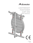
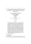
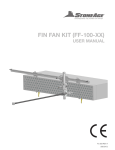
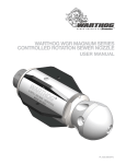
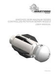
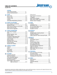
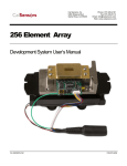
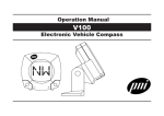
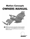
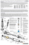
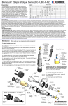
Deck Blaster User Manual
TABLE OF CONTENTS
1.0
2.0
3.0
4.0
5.0
6.0
INTRODUCTION
SAFETY WARNING
DESCRIPTION
PARTS LIST
ASSEMBLY DRAWING
APPENDIX
UH Swivel
UH-40
1.0 INTRODUCTION
This manual was prepared to provide the operator with the basic information needed to operate and
service this equipment. The operating recommendations in the manual will ensure that you receive
satisfactory performance. All operating personnel responsible for the care of this equipment should be
familiar with the information in this manual.
If you have any questions or problems with this equipment, please contact the distributor you obtained the
product from, or the manufacturer:
StoneAge, Inc.
466 S. Skylane Drive
Durango, CO 81303
970-259-2869 Phone 970-259-2868 Fax
www.stoneagetools.com
2.0 SAFETY WARNING
Operations with this equipment can be potentially dangerous if caution is not exercised prior to and during
tool use. Please read and follow all of these instructions, in addition to the guidelines in the WJTA
Recommended Practices handbook.
1.1
1.2
1.3
1.4
1.5
1.6
1.7
1.8
1.9
Only competent and trained persons should operate this equipment.
Do not exceed the maximum operating pressure specified for any component in a system.
This equipment should always be used with an operator controlled dump mechanism to
release the high pressure water.
The immediate work area should be marked off to keep out untrained persons.
All personnel in the area should wear eye and hearing protection, as well as other
protective clothing in accordance with specific conditions.
Jet thrust should be less than the weight of the machine. Care must be used in selecting
flow rate (Nozzle Size).
Inspect the equipment for visible signs of deterioration, damage, or improper assembly.
Do not operate until repaired. Make sure all threaded connections are tight and leak free.
Check to see that all control functions work properly before going to high pressure.
The person operating the equipment should have direct control of the dump system.
© 08/07
3.0 DESCRIPTION
The ultra high pressure Deck Blaster is an air-powered, self-propelled surface preparation machine. The
water exits through the nozzles as high velocity jets which are capable of cutting most paint, scale,
residues, membranes and chemical deposits. The tool is rated for 6 gpm at operating pressures up to
40,000 psi, but more flow may be used if additional weight is added to the dome area to keep it from
becoming tipsy and unstable. Note: During the first half-hour of use, the rotation speed should not
be run at maximum, but should be limited to 300-500 rpm, allowing the swivel seal and shaft to
"break-in."
AIR SUPPLY
The air supply should be capable of producing 50 to 80 cfm at 80 psi. The air line from the compressor to
the machine should be at least 3/4 inch. To operate the machine at full speeds (rotation and feed) the air
supply will need to be 80 cfm. Lower volumes will result in slower maximum speeds.
WATER SUPPLY
A 10-micron water filter upstream from the pump is recommended. Flush all hoses before use. Keep the
ends covered when not connected.
WATER SWIVEL
The UH high pressure water swivel is rated for 40,000 psi maximum operating pressure. When connecting
to the 90 degree inlet, make sure that the threaded port is lined up with the cone port of the inlet. The UH
has a high pressure seal which should be replaced when it begins to leak continuously at operating
pressure. The swivel should be greased after 40 to 80 hours of use. Keep the end nut and all connections
tight. Watch for leaks and shut down to repair. Please refer to the appendix for further detailed
information on the swivel.
NOZZLE HEAD
The bar head used on this assembly has 8 ports. Depending on the application, it may be better to plug
some ports and use fewer, larger nozzles (thick, heavy deposits) or to use more, smaller nozzles in all
ports (thin coatings, less damage to substrate.) The standoff distance can be adjusted by using the dome
height adjustment.
PRESSURE DUMP
The air actuated pressure dump valve is controlled by an air valve mounted on the push handle, and is
closed by lifting up on the dump handle bar. The exhausted flow is routed into the dome. The DB 025
valve is manufactured by Jetstream, of Houston, TX; part number 53620X; the DB 022 valve is
manufactured by Gardner Denver of Houston, TX part number 77-700314-AIR2.
SELF PROPULSION
The self-propulsion drive is actuated by the push-pull knob on the handle. When engaged, both drive
wheels are driven. Disengage the drive for easy turning or transport. The rate of advance can be
controlled by adjusting the needle valve on the exhaust of the drive air motor.
VACUUM
Vacuum connection is made to the 3" aluminum elbow on the dome. The skirt should be in contact with
the ground for best results.
© 08/07
4.0 PARTS LIST
BR 153
BR 155
BR 157
BUD 124
CB 114
CB 116
CST 148
DB 026
DB 045
DB 048
DB 072
DB 076
DB 078
DB 079
DB 080
DB 096
DB 103 H9S6-14
DB 110
DB 111
DB 123
DB 124-12
DB 125
DB 153
DB 154
DB 160-PC
DB 170
DB 077
DB 165
DB 166
DB 167
DB 168
DB 169
DB 251
DB 175
DB 190
DB 211
DB 225-GD
AF 060-H9
AF 062-H9
BR 158
CAT 662
DB 022
DB 045
FCT 147
WBW 148
DB 225-JS
DB 025
DB 026
DB 028
DB 045
DB 049
DB 224
DB 230
DB 233-18
DB 240
DB 242
DB 245
DB 246
DB 250
DB 310
FC 325
FCT 011
FCT 400
Muffler, P4
Muffler, P8
Fitting, P8J8
Valve, 3-Way
Fitting, Inlet
Nipple, P8
Tubing, 3/8 OD Nylon
Muffler, P4
Fitting, P12M HB12
Bracket, Lift
Fitting, P8M PL6
Hub, Axle
Hub, Friction
Key, Drive Axle
Spacer, Air Cylinder
Hose, High Pressure
Bar Head
Wheel, Machined
Bushing, Wheel
Elbow, Vacuum
Nipple, Vacuum
Weldment, Baffle
Rail, RHS
Rail, LHS
Gearbox
Assy, Air Cylinder
Bearing
Body
Piston
Bushing
O-Ring
O-Ring
Fitting, P2PL6
Axle, Drive
Chassis
Bracket, Air Valve
Assy, Dump Valve GD
Fitting, H9-.56 Type M
Fitting, H9-.88 Type M
Bushing, P8P12
Fitting, Elbow P12F
Dump Valve, Gardner Denver
Fitting, P12M-HB12
Fitting, Elbow P2M PL6
Muffler. P2
Assy, Dump Valve JS
Dump Valve, Jetstream
Muffler, P4
Fitting, P4M PL6
Fitting, P12M-HB12
Fitting, Elbow P12MF
Spacer
Weldment, Dome
Assy, Skirt Brush
Screw Jack
Dowel
Fitting, Tee P8MFF
Fitting, Tee P8FMF
Fitting, Elbow P8 PL6
Handle, Dump
Valve, Air Control
Wheel, Swivel Caster
Weldment, Push Handle
1
2
2
1
1
1
2 FT
1
1
1
1
2
1
1
1
1
1
2
2
1
1
1
1
1
1
1
1
1
1
1
1
2
1
1
1
2
1*
1
1
1
1
1
1
1
1
1*
1
1
1
1
1
4
1
1
1
1
2
1
1
1
1
1
1
© 03/07
GH 113
GP 053
GP 053.1
GP 057
GP 058
HRS 446.1
HRS 540
HRS 552
HRS 555
HRS 573
LM 016-4
SG 072
TB 024
TB 025
UH-40
Set Screw
Fitting, Pushlock J8 HB8
Pushlock Hose
Lubricator
Speed Control
Hose Clamp
Ball Valve
Fititng, Elbow P4J8
Hose, Dump
Fitting, Elbow P8J8
Air Motor
Key, Gearbox
Screw Handle
Key, Screw Handle
Air Belt Drive assembly
1
8
10 FT
1
1
2
1
4
1 FT
2
1
1
1
1
1 (see UH-40 manual for parts breakdown)
*Indicates optional choice
© 03/07
DB 110 Wheel, Machined (2)
DB 111 Bushing, Wheel (2)
DB 170 Assy, Air Cylinder
DB 080 Spacer, Air Cylinder
5.0 DB-XX EXPLODED SUB-ASSEMBLIES
DB 310 Dump Handle
FCT 400 Push Handle
BR 153 Muffler
LM 016-4 Air Motor (Gast 4AM)
BR 155 Muffler
HRS 552 Ftg,
Elbow P4J8 (4)
GP 058 Speed Control
BR 157 Ftg, P8J8
DB 245 Ftg, Tee P8 MFF
DB 072 Ftg, Push Connect
BUD 124 Valve
CST 148 Tubing, 3/8 OD
DB 211 Brkt, Air Valve
DB 160-PC Gearbox
DB 077 Bearing
DB 078 Hub, Friction
DB 166 Piston
DB 026 Muffler
FC 325 Valve, Air Control
DB 168 O-Ring
DB 169 O-Ring (2)
DB 165 Body
DB 251 Ftg, P2PL6
DB 167 Bushing
DB 079 Key
SG 072 Key
DB 048 Brkt, Lift
DB 153 Rail, RHS
DB 154 Rail, LHS
DB 123 Vacuum Elbow
DB 045 Ftg, P12M-.75 Hose
DB 124-12 Nipple
DB 230 Dome Weldment
DB 125 Baffle Weldment
DB 175 Axle, Drive
DB 076 Hub, Axle (2)
DB 049 Ftg, Elbow P12MF
DB 025 Dump Valve, 40K
DB 026 Muffler
CAT 662 Ftg, Elbow P12F
BR 158 Bushing, P8P12
AF 062-H9 Ftg, H9 to .88 Type M
DB 022 Dump Valve, 40K
DB 028 Ftg,
Elbow P4PL6
FCT 147 Ftg, Elbow
P2M-PL6
DB 224 Spacer (4)
WBW 148 Muffler
AF 060-H9 Ftg, H9 to .56 Type M
DB 045 Ftg, P12M-.75 Hose
DB 225-GD Dump Valve Assy
DB 045 Ftg, P12M-.75 Hose
DB 225-JS Dump Valve Assy
DB 233-18 Skirt Brush Assy
©04/10
5.1 DB-XX DESCRIPTION & ASSEMBLY VIEWS
Vacuum Elbow
DB 096 Hose Assy, 40K
UH-H9G12-90 Swivel
Rotation Speed Adjust Ball Valve
High Pressure Water Inlet
Dump Handle
Drive On/Off Valve
HRS 573 Ftg, 90° P8J8 (2)
Dump Air Valve
DB 246 Ftg, Tee P8 FMF
GP 053 Ftg, Pushlock (8)
CB 114 Ftg, Air Inlet
GP 057 Lubricator
Hose, Air Supply 20"
CST 148 Tubing, Dump 3/8 OD x 20"
Hose, Air Supply 19.5"
DB 225-JS or DB 225-GD Dump Valve Assy
Hose, Rotation 41.5"
Hose, Dump .75 ID x 12"
FC 311.2 Hose Clamp (2)
Hose, Drive 28.7"
DB 240 Screw Jack
DB 242 Dowel
DB 190 Chassis
TB 024 Screw Handle
TB 025 Key
Drive Speed Adjustment
FCT 011 Wheel, Swivel
Dome Height Adjustment
©03/07
8
7
6
5
4
3
Ite m
0
1
2
3
4
5
6
7
8
9
10
11
12
13
F
8
10
7
5
6
1
E
QTY
0
1
1
1
1
1
1
1
3
1
1
1
4
4
Pa rt No.
77-700314-AIR2
77-700305-AIR
77-700315
77-700304
77-700312
77-513048
77-513050
77-700155
16-15148
77-408705
77-700156
77-700163
77-408707
16-79012
2
1
De scription
FOOT GUN ASSY. 40K DUMP STYLE AIR, NO BASE
BLOCK. 40K AIR OPERATED DUMP TYPE FOOT GUN
CARTRIDGE. 40K HG/FG/DUMP TYPE TUMBLE BOX VALVE
DUMP TUBE ADAPTER. 40K DUMP
DUMP TUBE. FG (40K)
GLAND NUT. 3/8 HP
PLUG. 3/8 HP
ACTUATOR ADAPTER PLATE. 15K FG AIR
SCREW , SHC, SS, 1/4-20 X 3/4
VALVE AIR ACTUATOR
ACTUATOR ROD. 15K/20K FG AIR
SPACER BLOCK. AIR OPERATED FG FOOT GUN
SCREW . 10-24 X 1 1/2 SHCS SS
1/4 -20 SHCS 1-1/8 LONG SS.
F
E
D
D
C
C
9
B
A
2
13
11
3
4
12
Last revision:
ITEM 10, ACTUATOR ROD WAS 77-700651
Default Tolerances:
Proprietary Notice:
This design concept .XXX +/- .005
.XX +/- .010
is the exclusive
+/- .015
property of GDWJSI. .X
Reproduction in part
or whole is prohibited Tolerances and
without prior consent Practices per
Document:
of GDWJSI.
D98-60001
SCALE 1 : 1
8
B
Weight
7
6
5
4
LB
Cage Code
29731
3
GARDNER DENVER WATER JETTING SYSTEMS INC.
12300 N. Houston Rosslyn, Houston, TX. 77086 (281) 448-5800
Design By:
P. GOLDSMITH
Drawn:
AXP1108
Approve:
Date:
2/17/2006
FOOT GUN ASSY
40K DUMP STYLE AIR, NO BASE
P/N:
77-700314-AIR2
Sheet 1
2
of 1
Revision: 2
Rev. Date: 7/24/2006
1
A