1
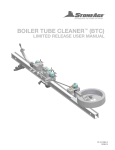
LIGHTWEIGHT
POSITIONER
(LWP-500)
USER MANUAL
PL 610 REV A
(10/2015)
TABLE OF CONTENTS
.MANUFACTURER’S INFORMATION.. . . . . . . . . . . . . . . . . . . . . . . . . . . . . . . . . . . . . . . . . . . . . . . . . . . . . . . . . . . . . . . . 3
SPECIFICATIONS. . . . . . . . . . . . . . . . . . . . . . . . . . . . . . . . . . . . . . . . . . . . . . . . . . . . . . . . . . . . . . . . . . . . . . . . . . . . . . . . . . . . . . . . . 3
DESCRIPTION OF EQUIPMENT AND INTENDED USE. . . . . . . . . . . . . . . . . . . . . . . . . . . . . . . . . . . . 3
KEY FEATURES. . . . . . . . . . . . . . . . . . . . . . . . . . . . . . . . . . . . . . . . . . . . . . . . . . . . . . . . . . . . . . . . . . . . . . . . . . . . . . . . . . . . . . . . . . . . 3
CE DECLARATION OF CONFORMITY. . . . . . . . . . . . . . . . . . . . . . . . . . . . . . . . . . . . . . . . . . . . . . . . . . . . . . . . . . . . 4
WARNING AND SAFETY INSTRUCTIONS. . . . . . . . . . . . . . . . . . . . . . . . . . . . . . . . . . . . . . . . . . . . . . . . . . . . . . . . 5
OPERATOR TRAINING. . . . . . . . . . . . . . . . . . . . . . . . . . . . . . . . . . . . . . . . . . . . . . . . . . . . . . . . . . . . . . . . . . . . . . . . . . . . . . . . . . 5
PERSONAL PROTECTIVE EQUIPMENT REQUIREMENTS.. . . . . . . . . . . . . . . . . . . . . . . . . . . . . . 5
SAFETY LABEL DEFINITIONS. . . . . . . . . . . . . . . . . . . . . . . . . . . . . . . . . . . . . . . . . . . . . . . . . . . . . . . . . . . . . . . . . . . . . . . 5
PRE-RUN SAFETY CHECK. . . . . . . . . . . . . . . . . . . . . . . . . . . . . . . . . . . . . . . . . . . . . . . . . . . . . . . . . . . . . . . . . . . . . . . . . . . 6
SYSTEM ASSEMBLY - OVERVIEW .. . . . . . . . . . . . . . . . . . . . . . . . . . . . . . . . . . . . . . . . . . . . . . . . . . . . . . . . . . . . . . . . . . 7
LIGHTWEIGHT POSITIONER - OVERVIEW . . . . . . . . . . . . . . . . . . . . . . . . . . . . . . . . . . . . . . . . . . . . . . . . . . . . . . 8
LIGHTWEIGHT POSITIONER CLAMP SELECTION.. . . . . . . . . . . . . . . . . . . . . . . . . . . . . . . . . . . . . . . . . 9
LIGHTWEIGHT POSITIONER SET-UP.. . . . . . . . . . . . . . . . . . . . . . . . . . . . . . . . . . . . . . . . . . . . . . . . . . . . . . . . . . . . 10
STORAGE, TRANSPORTATION, AND HANDLING. . . . . . . . . . . . . . . . . . . . . . . . . . . . . . . . . . . . . . . . . . . . 12
MAINTENANCE. . . . . . . . . . . . . . . . . . . . . . . . . . . . . . . . . . . . . . . . . . . . . . . . . . . . . . . . . . . . . . . . . . . . . . . . . . . . . . . . . . . . . . . . . . . . . . . . . 12
PARTS DIAGRAMS. . . . . . . . . . . . . . . . . . . . . . . . . . . . . . . . . . . . . . . . . . . . . . . . . . . . . . . . . . . . . . . . . . . . . . . . . . . . . . . . . . . . . . . . . . . . 13
TERMS AND CONDITIONS. . . . . . . . . . . . . . . . . . . . . . . . . . . . . . . . . . . . . . . . . . . . . . . . . . . . . . . . . . . . . . . . . . . . . . . . . . . . . . . 17
2
866-795-1586 • WWW.STONEAGETOOLS.COM
MANUFACTURER’S INFORMATION
StoneAge Inc.
Andrew Birt Consulting Ltd.
466 S. Skylane Drive
UK
Durango, CO 81303, USA
Phone: 970-259-2869
Toll Free: 866-795-1586
www.stoneagetools.com
This manual must be used in accordance with all applicable national laws. The manual shall be regarded as a part of the machine
and shall be kept for reference until the final dismantling of the machine, as defined by applicable national law(s).
SPECIFICATIONS
Lightweight Positioner Weight:
120 lbs (54.4 kg)
(Includes 6ft rails, horiz., vert., and
idler carriage, and 4 clamps)
DESCRIPTION OF EQUIPMENT AND
INTENDED USE
The Lightweight Positioner can be mounted to a variety of heat exchanger
tube bundles and has pneumatic powered horizontal and vertical drives.
It is intended to be used with AUTOBOX™ (ABX-2L) HOSE TRACTOR
and the AUTOBOX™ (ABX-500-V2).
KEY FEATURES:
• • • • • Modular, lightweight design
Quick install drive carriages
Utilizes 2.5 in. (6.35 cm) box rail
Stainless Steel air motors
Variety of clamp and bolt-on attachment options are available
866-795-1586 • WWW.STONEAGETOOLS.COM
3
CE DECLARATION OF CONFORMITY
In accordance with BS EN ISO/IEC 17050-1:2010
We:
StoneAge, Inc. 466 South Skylane Drive Durango, CO 81303, USA
Declare that:
Equipment: Lightweight Positioner
Model name: LWP-500 Is in accordance with the following Directives:
2006/42/EC Conforms to the Essential Health and Safety Requirements of the Machinery Directive
Has been designed and manufactured to the relevant parts of the following specifications:
EN ISO 12100:2010
Safety of machinery - General principles for design - Risk assessment and risk reduction
I hereby declare that the equipment named above has been tested and found to comply with the relevant sections of the
above referenced specifications and directives.
Signed ______________________________________________________
Date _
08/23/2015__________
Andrew Birt
Independent Dealer Manager
StoneAge, Inc., Worcester, UK
The technical file for the Lightweight Positioner (LWP-500) User Manual is maintained at: StoneAge, Inc. 466 South
Skylane Drive, Durango, CO 81303, USA
4
866-795-1586 • WWW.STONEAGETOOLS.COM
WARNING AND SAFETY INSTRUCTIONS
OPERATOR TRAINING
Managers, Supervisors, and Operators MUST be trained in Health
and Safety Awareness of High-pressure Water Jetting and hold
a copy the Water Jetting Association (WJA) Code of Practice, or
equivalent (see www.waterjetting.org.uk).
Operators MUST be trained to identify and understand all applicable
standards for the equipment supplied. Operators should be trained
in manual handling techniques to prevent bodily injury.
StoneAge has designed and manufactured this equipment
considering all hazards associated with its operation. StoneAge
assessed these risks and incorporated safety features in the design.
StoneAge WILL NOT accept responsibility for the results of misuse.
Operators MUST read, understand, and follow the Operational and
Training Requirements (Section 7.0) of WJTA-IMCA’s Recommended
Practices For The Use Of High-pressure Waterjetting Equipment, or
equivalent.
Operators MUST read, understand and follow the Warnings,
Safety Information, Assembly, Installation, Connection, Operation,
Transport, Handling, Storage, and Maintenance Instructions detailed
in this manual.
The risk assessment MUST consider potential material or substance
hazards including:
• • IT IS THE RESPONSIBILTY OF THE INSTALLER/OPERATOR to
conduct a job specific risk assessment prior to use. Job specific risk
assessment MUST be repeated for each different set up, material,
and location.
• The risk assessment MUST conform to the Health and Safety at
Work Act 1974 and other relevant Health and Safety legislation.
• • • • • • • • • PERSONAL PROTECTIVE EQUIPMENT REQUIREMENTS
Use of Personal Protective Equipment (PPE) is dependent on
the working pressure of water and the cleaning application.
Managers, Supervisors, and Operators MUST carry out a job
specific risk assessment to define the exact requirements for PPE.
See Protective Equipment for Personnel (Section 6) of WJTAIMCA’s Recommended Practices For The Use Of High-pressure
Waterjetting Equipment for additional information.
Hygiene - Operators are advised to wash thoroughly after all
waterjetting operations to remove any waterblast residue which may
contain traces of harmful substances.
First aid provision - users MUST be provided with suitable first aid
facilities at the operation site.
Aerosols
Biological and microbiological (viral or bacterial) agents
Combustible materials
Dusts
Explosion
Fibers
Flammable substances
Fluids
Fumes
Gases
Mists
Oxidizing Agents
PPE may include:
• Eye protection: Full face visor
• Foot protection: Kevlar® brand or steel toe capped,
waterproof, non-slip safety boots
• Hand protection: Waterproof gloves
• Ear protection: Ear protection for a minimum of 85 dBA
• Head protection: Hard hat that accepts a full face visor and
ear protection
• Body protection: Multi-layer waterproof clothing approved for
waterjetting
• Hose protection: Hose shroud
• Respiratory protection: May be required; refer to job specific
risk assessment
SAFETY LABEL DEFINITION
The Lightweight Positioner
(LWP-500) has the potential to
cause serious injury if fingers,
hair, or clothing become
caught between the rollers.
866-795-1586 • WWW.STONEAGETOOLS.COM
5
WARNING AND SAFETY INSTRUCTIONS
WARNING
Operations with this equipment can be potentially hazardous.
Caution MUST be exercised prior to and during machine and water
jet tool use. Please read and follow all of these instructions, in addition
to the guidelines in the WJTA Recommended Practices handbook,
available online at www.wjta.org. Deviating from safety instructions
and recommended practices can lead to severe injury and/or death.
Refer to WJTA-IMCA’s, Recommended Practices For The Use Of
High-pressure Waterjetting Equipment and/or The Water Jetting
Association’s, WJA Code of Practice for additional safety information.
• Complete a job specific risk assessment and act on the resulting
actions.
• Adhere to all site specific safety procedures.
• Ensure the waterblasting zone is properly barricaded and that
warning signs are posted.
• Ensure the work place is free of unnecessary objects (e.g. loose
parts, hoses, tools).
• Ensure all Operators are using the correct Personal Protective
Equipment (PPE).
• Do not exceed the maximum operating pressure specified for
any component in a system.
• The immediate work area MUST be marked off to keep out
untrained persons.
• Inspect the equipment for visible signs of deterioration,
damage, and improper assembly. Do not operate if damaged,
until repaired.
• Make sure all threaded connections are tight and free of leaks.
• Check that the air hoses are properly connected and tight.
• Users of the Lightweight Positioner (LWP-500) MUST be
trained and/or experienced in the use and application of highpressure technology and cleaning, as well as all associated
safety measures, according to the WJTA Recommended
Practices for the use of High-pressure Waterjetting Equipment.
• Check all hoses and accessories for damage prior to use. Do
not use damaged items. Only high quality hoses intended for
waterblast applications should be used as high-pressure hoses.
• Check all high-pressure threaded connections for tightness.
• 6
PRE-RUN SAFETY CHECK
An anti-withdrawal device (back-out preventer) MUST be used
at all times. The back-out prevention device is the Hose Stop
Collet located within the Hose Guide Assembly. StoneAge
offers several different size Hose Stop Collets. The Collet Size
Reference guide is located on the Hose Guide Assembly.
• The Control Box should be located in a safe location where
the Operator has good visibility of the pipe and hose. The
Lightweight Positioner (LWP-500) and Control Box MUST be
supervised at all times and should never be left unattended.
• Always de-energize the system before servicing or replacing any
parts. Failure to do so can result in severe injury and/or death.
• When moving the Lightweight Positioner (LWP-500) lift with
care to prevent bodily injury.
• **Ensure
that a anti-withdrawal device (back-out
preventer), whip checks (hose whips), and all other
applicable safety devices are installed and set-up
properly.**
• Ensure the doors of the Lightweight Positioner (LWP-500) are
closed and securely latched.
• Test the Control Box before operating the Lightweight Positioner
(LWP-500) with high-pressure water to verify the control valves
move the hose in the intended direction, and that the dump valve
and hose clamp are working properly.
• Ensure that Operators never connect, disconnect, or tighten
hoses, adapters, or accessories with the high-pressure water
pump unit running.
• Ensure no personnel are in the hydroblasting zone.
866-795-1586 • WWW.STONEAGETOOLS.COM
SYSTEM ASSEMBLY - OVERVIEW
LIGHTWEIGHT POSITIONER (LWP-500)
ASSEMBLY
RAIL STOP
HORIZONTAL
DRIVE
ASSEMBLY
RAIL STOP
2.5” SLOTTED RAIL
RAIL STOP
2.5” SLOTTED RAIL
CLAMP (3 OPTIONS
FOR DIFFERENT
FLANGE TYPES ARE
AVAILABLE)
VERTICAL
DRIVE
ASSEMBLY
NOTE: Heat exchanger tube
bundle face, shown for
graphic representation only.
Not included in assembly.
2.5” NON-SLOTTED RAIL
RAIL STOP
BLANK
HORIZONTAL
ASSEMBLY
866-795-1586 • WWW.STONEAGETOOLS.COM
7
LIGHTWEIGHT POSITIONER - OVERVIEW
LIGHTWEIGHT POSITIONER
RAIL STOP ASSEMBLIES
RAIL EXTENSIONS
(2,4, OR 6 FT LENGTHS)
(.61 m, 1.2 m, OR 1.8 m)
HORIZONTAL
DRIVE
ASSEMBLY
VERTICAL
SLOTTED
RAIL
POSITIONER
CONTROL LINE
ASSEMBLY
HORIZONTAL
SLOTTED RAIL
25 FT / 7.6 m
STANDARD
LENGTH
CLAMP TYPES
(LWP 625 KIT
INCLUDES ALL KITS
SHOWN HERE)
VERTICAL
DRIVE
ASSEMBLY
NON-SLOTTED RAIL
SLOTTED
QUICK CLAMP
(LWP 620 KIT
CONTAINS 4)
QUICK CLAMP
(LWP 621 KIT
CONTAINS 4)
RAIL STOP
ASSEMBLY
8
BLANK HORIZONTAL
ASSEMBLY
866-795-1586 • WWW.STONEAGETOOLS.COM
PLATE CLAMP
(LWP 622 KIT
CONTAINS 2)
LIGHTWEIGHT POSITIONER CLAMP SELECTION
CLAMP SELECTION
Is dependent upon the heat exchanger geometry, bolt holes, hole spacing,
and flange accessibility.
CLAMP TYPES
(LWP 625 KIT
INCLUDES ALL KITS
SHOWN HERE)
QUICK CLAMPS
Use if heat exchanger flange provides a robust clamping surface or if
flange holes are inaccessible. Align clamps on the surface of the flange to
maximize flange engagement to clamps. (Figure 2)
SLOTTED QUICK AND PLATE CLAMPS
Use if heat exchanger flange has bolt holes that are easily accessible.
Use quick clamps or plate clamps, depending on the spacing of the hole
pattern. (Figures 1 & 3)
SLOTTED
QUICK CLAMP
(LWP 620 KIT
CONTAINS 4)
QUICK CLAMP
(LWP 621 KIT
CONTAINS 4)
FIGURE 1
FIGURE 2
PLATE CLAMP
(LWP 622 KIT
CONTAINS 2)
FIGURE 3
866-795-1586 • WWW.STONEAGETOOLS.COM
9
LIGHTWEIGHT POSITIONER SET-UP
LIGHTWEIGHT POSITIONER STEP BY STEP SET-UP
1. Mount the appropriate frame Positioner Clamps to the tube
bundle as shown on the previous page. (Shown in Figure
1 with Slotted Quick Clamps) Positioner Clamps should be
aligned horizontally with the direction of the tube rows. (Figure
1)
NOTE: Heat exchanger tube bundle face, shown for
graphic representation only. Not included in assembly.
FIGURE 1
2. Insert the Top Rail (slots facing out) into the upper mounting
brackets. If the rail is not closely aligned with the tube rows,
loosen one of the upper mounting brackets and adjust until
the top rail is parallel with the horizontal tube rows. Tighten the
clamps securing the rail to the mounting brackets, and ensure
upper mounting brackets are securely clamped or bolted to
the tube bundle flange. (Figure 2)
FIGURE 2
3. Insert the Lower Rail (non-slotted) into the lower mounting
brackets. It is not critical that this rail is aligned as precisely as
the top rail, but it should be close to parallel with the top rail for
best performance. Tighten the clamps securing the rail to the
mounting brackets, and ensure lower mounting brackets are
securely clamped or bolted to the tube bundle flange. (Figure
3)
FIGURE 3
4. Loosen the Quick Adjust Handle and pull the gearbox away
from the carriage plate. This will allow the Horizontal Drive
Carriage to slide onto the rail without pneumatic power to
rotate the drive. Center the carriage on the top rail and push
the gearbox back toward the carriage plate. This will engage
the gear into the rail slots. Verify the gear is engaging the slots
correctly and retighten the adjustable handle. (Figure 4)
FIGURE 4
10
866-795-1586 • WWW.STONEAGETOOLS.COM
LIGHTWEIGHT POSITIONER SET-UP
5. Slide the Idler Carriage onto the Lower Non-Slotted Rail.
(Figure 5)
FIGURE 5
6. Loosen the Large Adjustable Handle for the Vertical Rail
Clamp. Align the Idler Carriage with the vertical rail clamp on
the horizontal carriage. Install the Vertical Rail with (slots
facing out) down through the horizontal carriage clamp
and between the rollers on the idler carriage. Adjust the
position of the vertical rail as required and secure the clamp
on the horizontal carriage by tightening the large adjustable
handle. (Figure 6)
FIGURE 6
7. Loosen the Quick Adjust Handle and pull the gearbox
away from the carriage plate. This will allow the Vertical
Drive Carriage to slide onto the rail without pneumatic
power to rotate the drive. Center the carriage on the vertical
rail and push the gearbox back toward the carriage plate.
This will engage the gear into the rail slots. Verify the gear
is engaging the slots correctly and retighten the adjustable
handle. (Figure 7)
FIGURE 7
8. Install the four Rail Stops at both ends of the top, slotted,
horizontal rail, and both ends of the vertical slotted rail.
(Figure 8)
NOTE: Verify the mounting brackets and rail clamps
are securely tightened and that the drive carriages
are securely engaged and the adjustable handles are
tightened.
Never loosen the vertical gearbox once the guide
assembly and tractor are installed, as it may result in the
carriage falling vertically down. This may cause damage
and/or injury.
FIGURE 8
866-795-1586 • WWW.STONEAGETOOLS.COM
11
MAINTENANCE
Maintenance Item
Frequency
Maintenance Required
Forward, reverse, and clamp fittings
Before each use
Inspect threads for wear or damage.
Carriage rollers
Every 100 Hours of use Lubricate Zerks on all Carriage Rollers using any multipurpose
NLGI 2 grease.
Vertical and Horizontal Rails
As Needed
Inspect for wear that would allow Carriage Rollers to slip off.
Replace Rail as needed.
All components the hoses pass through
After each use
Most wear parts are made from 17-4 PH stainless steel and
should have a very long life. However, as wear occurs the
rounded edges could become sharp and damage hoses. Any
components showing excessive wear should be replaced.
STORAGE, TRANSPORTATION, AND HANDLING
Use mild soapy water to clean the machine in order to remove corrosive materials. Before storing the unit, use compressed air to blow
off debris and moisture. Apply a small amount of air tool oil directly into the Horizontal and Vertical Drive fittings. Then, briefly operate the
controls at slow speed for a short duration in each direction to coat the interior parts of the motor. Install the dust caps onto all fittings to
keep moisture and dirt out.
The Lightweight POSITIONER (LWP-500), can be broken down into smaller components that should be stored in a clean and dry area.
Contact StoneAge for Safety Data Sheets for material usage, a complete list of spare part numbers, and service instructions for
the Lightweight Positioner.
12
866-795-1586 • WWW.STONEAGETOOLS.COM
PARTS DIAGRAM
LIGHTWEIGHT POSITIONER
(LWP-500)
#
PART NUMBER
QTY
1
BR 002-XX 2.5 BOX RAIL EXTRUSION
1
2
BU 002-XX 2.5 BOX RAIL EXTRUSION, SLOTTED
2
3
LWP-500.1 LIGHTWEIGHT POSITIONER PARTS
1
866-795-1586 • WWW.STONEAGETOOLS.COM
13
PARTS DIAGRAM
LIGHTWEIGHT POSITIONER (LWP 501)
HORIZONTAL POSITIONER
NOTE:
1. BLUE LOCTITE: PN: 243 OR EQUIVALENT
2. BLUE GOOP IS A SWAGELOK BRAND ANTI-SEIZE. AN EQUIVALENT ALTERNATIVE IS ACCEPTABLE.
14
#
PART NUMBER
QTY.
9
SRT 547 MOUNT BLOCK
1
1
2
BR 055-SS ROLLER ASSY
4
10
SRT 548 HORIZONTAL MOUNTING PLATE
1
GS 325-03 SHCS .25-20 X .75 SS (TB 050)
2
11
SRT 549 HORIZONTAL RAIL CLAMP
1
3
GS 325-04 SHCS .25-20 X 1.00 SS (BC 053)
2
12
SRT 551 CLAMP FINGER
1
4
GS 331-20 SHCS .31-18 X 5.00 SS
4
13
SRT 552 ADJUSTABLE RAIL CLAMP
1
5
GSSH 0375-0500-SS SHOULDER SCREW
2
14
SRT 556 ADJUSTABLE HANDLE .38-16 X 1.56 SS
1
6
LP 652-1.38 AXLE-ZERK
4
15
SRT 557 ADJUSTABLE HANDLE .25-20 X 1.19 SS
1
7
SRT 506 HORIZONTAL CARRIAGE PLATE
1
16
LWP 503 MOTOVARIO DRIVE ASSY
1
8
SRT 546 HANDLE MOUNT BLOCK
1
866-795-1586 • WWW.STONEAGETOOLS.COM
PARTS DIAGRAM
LIGHTWEIGHT POSITIONER (LWP 502)
VERTICAL POSITIONER
NOTE:
1. BLUE LOCTITE: PN: 243 OR EQUIVALENT
2. BLUE GOOP IS A SWAGELOK BRAND ANTI-SEIZE. AN EQUIVALENT ALTERNATIVE IS ACCEPTABLE.
#
PART NUMBER
QTY.
12
SRT 579 CLEVIS PIN, SS WITH E-RING
1
1
2
BR 055-SS ROLLER ASSY
4
13
SRT 582 VERTICAL BOTTOM PIPE CLAMP
1
GB 337-08 BOLT, HEX .37-16 X 2.00 SS
2
14
SRT 583 VERTICAL TOP PIPE CLAMP
1
3
GS 325-03 SHCS .25-20 X .75 SS (TB 050)
6
15
SRT 585 CLAMP SPACER
1
4
GS 337-07 SHCS .37-16 X 1.75 SS
2
16
SRT 586 SMALL CLAMP SPRING
1
5
GSS 525-20-75CU SET SCREW
1
17
SRT 592 T-NUT FULL THD .38-16
2
6
GW 337-F FLAT WASHER SS
6
18
LWP 512 VERTICAL CARRIAGE PLATE
1
9
GW 337-L LOCK WASHER SS
6
19
LWP 513 UPPER RAIL CLAMP
1
8
LP 652-1.38 AXLE-ZERK
4
20
LWP 514 LOWER RAIL CLAMP
1
9
SRT 557 ADJUSTABLE HANDLE .25-20 X 1.19 SS
1
21
GB 337-05 BOLT, HEX .37-16 X 1.25 SS
4
10
SRT 571 VERTICAL HANDLE MOUNT BLOCK
1
22
LWP 503 MOTOVARIO DRIVE ASSY
1
11
SRT 573 VERTICAL MOUNT BLOCK
1
866-795-1586 • WWW.STONEAGETOOLS.COM
15
PARTS DIAGRAM
LIGHTWEIGHT POSITIONER (LWP 503)
MOTOVARIO DRIVE ASSEMBLY
NOTE:
1. RED LOCTITE: PN: 262 OR EQUIVALENT
2. BLUE LOCTITE: PN: 242 OR EQUIVALENT
3. BLUE GOOP IS A SWAGELOK BRAND ANTI-SEIZE. AN EQUIVALENT ALTERNATIVE IS ACCEPTABLE.
4. REMOVE MOUNTING FLANGE THAT COMES WITH GEARBOX. KEEP INPUT SHAFT FACING UP TO PREVENT OIL LEAKAGE.
5. ASSURE LANYARD EYELET CAN ROTATE
#
16
PART NUMBER
QTY.
15
LWP 516 WASHER, OVERSIZED
1
1
GB 325-03 BOLT, HEX .25-20 X .75 SS
1
16
LWP 520.1 AIR MOTOR
1
2
GS 316-01 SHCS .16-32 X .25 SS
2
17
LWP 542 NUT PLATE
2
3
GS 319-025 SHCS .19-24 X .62 SS
12
18
LWP 550 MOTOVARIO NMRV030301600_625IN
1
4
GS 319-045 SHCS .19-24 X 1.125 SS
4
19
RJ 008 O-RING
1
5
GS 3M6-30-1.0 SHCS M6X1.0 X 30 SS
4
20
SL 010 SEAL
1
6
LWP 504 TOP MOTOR MOUNT PLATE
1
21
SRT 209.1 LANYARD ASSY (CUT TO LENGTH)
2
7
LWP 505 GEAR COVER
1
22
SRT 457 CHECK VALVE, BSPP2
1
8
LWP 506 HANDLE SIDE MOUNTING PLATE
1
23
SRT 520 SPUR GEAR SS (6 DP, 14.5 PA, 26 T)
1
9
LWP 507 IDLE SIDE MOUNTING PLATE
1
24
SRT 531 FTG, ADAPTER BSPP2 X P2
3
10
LWP 508 REAR COVER
1
25
SRT 537 RETAINING RING, SS EXTERNAL
2
11
LWP 509 MOTOVARIO SHAFT
1
26
SRT 553 FTG, J4 MALE X P2 MALE
2
12
LWP 510-001 STEP SHAFT
1
27
SRT 555 MALE X FEMALE P2 ELBOW 45
2
13
LWP 511 TOP GEARBOX SPACER
1
28
SRT 558 J4 CAP
2
14
LWP 515 SPACER
4
29
WBW 148 MUFFLER
1
866-795-1586 • WWW.STONEAGETOOLS.COM
PARTS DIAGRAM
LIGHTWEIGHT POSITIONER (SRT 560)
BLANK HORIZONTAL ASSEMBLY
#
PART NUMBER
QTY.
4
SRT 561 BLANK HORIZONTAL CARRIAGE PLATE
1
1
BR 052-2.0 AXLE-ZERK
2
5
SRT 562 BLANK ROLLER SPACER
1
2
BR 055-SS ROLLER ASSY
6
6
GS 337-03 SHCS .37-16 X .75 SS
2
3
LP 652-1.38 AXLE-ZERK
4
LIGHTWEIGHT POSITIONER (BU 152)
RAIL STOP ASSEMBLY
#
PART NUMBER
QTY.
1
BU 149 PLATE, RAIL STOP
1
2
BR 060 RAIL CLAMP
1
3
GB 537-05 BOLT, HEX .37-16 X 1.25
1
4
BU 151 HANDLE
1
866-795-1586 • WWW.STONEAGETOOLS.COM
17
PARTS DIAGRAM
LIGHTWEIGHT POSITIONER (LWP 518 )
SLOTTED QUICK CLAMP ASSEMBLY
NOTE:
1.
2.
3.
4.
18
BLUE GOOP IS A SWAGELOK BRAND ANTI-SEIZE. AN EQUIVALENT ALTERNATIVE IS ACCEPTABLE.
BLUE LOCTITE: PN: 242 OR EQUIVALENT
RED LOCTITE: PN: 262 OR EQUIVALENT
IF SHAFT DOES NOT SLIDE THROUGH BUSHING EASILY, REAM BUSHING ID TO SHAFT OD +.005/ +.001.
#
PART NUMBER
QTY.
13
LWP 529 FLANGE CLAMP LEVER
1
1
GS 325-03 SCREW, SHC, STAINLESS, 1|4-20 UNC X 0.750L
2
14
LWP 530 FLANGE CLAMP KNOB
2
2
GS 325-04 SCREW, SHC, STAINLESS, 1|4-20 UNC X 1.000L
2
15
LWP 531 RAIL CLAMP LEVER
1
3
GSSH 0312-0750-SS SHOULDER SCREW
1
16
LWP 532 RAIL CLAMP KNOB
2
4
LWP 517 BALL NOSE SPRING PLUNGER
1
17
LWP 533 NUT, BRASS, 3/4-10
1
5
LWP 521 QUICK CLAMP BASE PLATE
1
18
LWP 534 NUT, SQUARE, 3/4-10
1
6
LWP 522 FLANGE CLAMP PLATE
1
19
LWP 535 THRUST WASHER
1
7
LWP 523 NUT CAP
1
20
LWP 545 FLANGED BUSHING
1
8
LWP 524 RAIL CLAMP PLATE
1
21
LWP 546 RETAINING RING
1
9
LWP 525 STATIC RAIL CLAMP
1
22
LWP 547 SHIM
1
10
LWP 526 QUICK RAIL CLAMP FINGER
1
23
LWP 548 FLANGED NUT
1
11
LWP 527 FLANGE CLAMP SCREW
1
24
LWP 555 BOLT, 3/4-10 X 7.00L, FULLY THREADED
1
12
LWP 528 RAIL CLAMP SHAFT
1
25
SRT 333 NYLOCK HEX JAM NUT SS THIN
1
866-795-1586 • WWW.STONEAGETOOLS.COM
PARTS DIAGRAM
LIGHTWEIGHT POSITIONER (LWP 519)
PLATE CLAMP ASSEMBLY
NOTE:
1. BEFORE INSTALLING KNOB, INSTALL MIDDLE SPRING PIN & ADJACENT FLAT WASHER. APPLY A THIN LAYER OF GENERAL PURPOSE GREASE
TO UNTHREADED SECTION OF SHAFT THEN INSTALL SHAFT UP THROUGH SLIDE CLAMP. THREAD KNOB ON SHAFT AS FAR AS POSSIBLE
WHILE STILL ALLOWING SHAFT TO FREELY ROTATE, THEN BACK OFF TO FIRST SPOT FOR SPRING PIN INSTALLATION.
2. APPLY A THIN LAYER OF GENERAL PURPOSE GREASE TO ALL SURFACES OF PLATE THAT CLAMP WILL SLIDE ON
3. THREAD PLUNGER IN SO BALL ENGAGES DETENTS IN SHAFT.
DO NOT ALLOW BODY OF PLUNGER TO TOUCH SHAFT.
4. BLUE GOOP IS A SWAGELOK BRAND ANTI-SEIZE. AN EQUIVALENT ALTERNATIVE IS ACCEPTABLE.
5. BLUE LOCTITE: PN: 242 OR EQUIVALENT
#
PART NUMBER
1
BR 060 RAIL CLAMP
QTY.
2
2
GB 337-05 BOLT, HEX HEAD, STAINLESS, 3|8-16 UNC X 1.250L
4
3
GW 337-L WASHER, LOCK, 3/8”, STAINLESS
4
4
LWP 536 MODIFIED KNOB
1
5
LWP 537 SLIDE CLAMP
1
6
LWP 539 BALL NOSE SPRING PLUNGER
1
7
LWP 540 PLATE CLAMP BASE PLATE
1
8
LWP 541 FLAT WASHER
2
9
LWP 543 SPRING PIN
3
10
LWP 544 CLAMP SHAFT
1
11
LWP 549 BRONZE THRUST BUSHING
1
866-795-1586 • WWW.STONEAGETOOLS.COM
19
PARTS DIAGRAM
LIGHTWEIGHT POSITIONER (LWP 552)
SLOTTED QUICK CLAMP ASSEMBLY
NOTE:
1. BLUE GOOP IS A SWAGELOK BRAND ANTI-SEIZE. AN EQUIVALENT
ALTERNATIVE IS ACCEPTABLE.
2. BLUE LOCTITE: PN: 242 OR EQUIVALENT
3. RED LOCTITE: PN: 262 OR EQUIVALENT
20
#
PART NUMBER
1
GS 325-03 SCREW, SHC, STAINLESS, 1|4-20 UNC X 0.750L
QTY.
2
2
GSSH 0312-0750-SS SHOULDER SCREW
1
3
LWP 517 BALL NOSE SPRING PLUNGER
1
4
LWP 524 RAIL CLAMP PLATE
1
5
LWP 525 STATIC RAIL CLAMP
1
6
LWP 526 QUICK RAIL CLAMP FINGER
1
7
LWP 528 RAIL CLAMP SHAFT
1
8
LWP 531 RAIL CLAMP LEVER
1
9
LWP 532 RAIL CLAMP KNOB
2
10
LWP 535 THRUST WASHER
1
11
LWP 551 SLOTTED QUICK CLAMP BASE PLATE
1
12
SRT 333 NYLOCK HEX JAM NUT SS THIN
1
866-795-1586 • WWW.STONEAGETOOLS.COM
PARTS DIAGRAM
LIGHTWEIGHT POSITIONER (SRT 115)
POSITIONER CONTROL LINE ASSEMBLY
#
PART NUMBER
QTY
1
SRT 121 POSITIONER AIR LINE COVER 26FT OAL
1
2
SRT 118 CONTROL LINE, RED
2
3
SRT 119 FEMALE J4 SWIVEL X .250 I.D. HOSE BARB
4
866-795-1586 • WWW.STONEAGETOOLS.COM
21
TERMS AND CONDITIONS
1. Acceptance of Terms and Conditions. These Terms and Conditions
shall operate as Seller’s acceptance of Buyer’s purchase order, and such
acceptance is made expressly conditional on assent by Buyer to the
Terms and Conditions. Such assent shall be deemed to have been given
unless written notice of objection to any of such Terms and Conditions
(including inconsistencies between Buyer’s purchase order and this
acceptance) is given by Buyer to Seller promptly on receipt hereof.
Seller desires to provide its Buyer with prompt and efficient service.
However, to negotiate individually the terms of each sales contract
would substantially impair Seller’s ability to provide such service.
Accordingly, products furnished and services rendered by Seller are
sold only on the Terms and Conditions stated herein. Notwithstanding
any Terms or Conditions on Buyer’s order, Seller’s performance of any
contract is expressly made conditional on Buyer’s agreement to Seller’s
Terms and Conditions of sale unless otherwise specifically agreed to in
writing by Seller. In the absence of such agreement, commencement of
performance, shipment and/or delivery shall be for Buyer’s convenience
only and shall not be deemed or construed to be an acceptance of
Buyer’s Terms and Conditions. PRODUCTS SOLD BY SELLER ARE
DESIGNED AND INTENDED TO BE USED AT HIGH PRESSURES AND
SPEEDS, AND MAY BE DANGEROUS IF OPERATED IMPROPERLY OR
WITHOUT THE USE OF APPROPRIATE SAFETY DEVICES AND GUARDS.
BUYER IS CAUTIONED TO CAREFULLY READ AND UNDERSTAND
THESE TERMS AND CONDITIONS, AS THEY HAVE IMPORTANT LEGAL
CONSEQUENCES.
2. Payment/Prices. Unless other arrangements have been made in
writing between Seller and Buyer, payment for product delivered shall be
made upon receipt of invoice. The prices shown on the face hereof are
those currently in effect. Prices invoiced shall be per price list in effect at
the time of shipment. Prices are subject to increase for inclusion of any
and all taxes which are applicable and which arise from the sale, delivery
or use of Seller’s products or services and for the collection of which
Seller is or may be responsible to any governmental authority unless
acceptable exemption certificates are provided by Buyer in accordance
with law. Buyer shall pay all charges for transportation and delivery and
all excise, order, occupation, use or similar taxes, duties, levies, charges
or surcharges applicable to the equipment or services being purchased,
whether now in effect or hereafter imposed by any governmental
authority, foreign or domestic.
3. Warranty. Subject to the limitations and conditions hereinafter set
forth, Seller warrants to the original Buyer that its products are free from
defects in workmanship and material for a period of one (1) year from
shipment date. Seller’s obligation under this warranty shall be limited
to repairing, replacing or issuing a credit for, at Seller’s option, any
products or services it finds to be defective in material or workmanship.
In no event shall Seller be liable for any incidental, consequential or
indirect damages of any kind. THIS WARRANTY SHALL BE IN LIEU
OF ANY OTHER WARRANTY, EXPRESSED OR IMPLIED, INCLUDING
ANY WARRANTY FOR MERCHANTABILITY OR FITNESS FOR ANY
PARTICULAR PURPOSE. No statement or recommendation made by
Seller or its representative to Buyer or User shall constitute a warranty by
Seller or a waiver or modification to any of the provisions hereof or create
any liability for Seller. All warranty claims are subject to the exclusions
and limitations set forth below:
22
a. The warranty shall not apply if the product or service (1) has been
subject to misuse, negligence or accident; (2) has not been installed or
operated in accordance with Seller’s recommendations; (3) has been
operated under more severe conditions than those specified for the
particular product or service; (4) has been operated beyond the rated
capacity of the product; or (5) has been repaired or altered outside
Seller’s facilities or in any way so as, in Seller’s judgment, to affect its
stability or reliability.
b. Products that Seller furnishes, but does not manufacture, carry
only the warranty of the Manufacturer of such products. Where other
Manufacturers’ or Suppliers’ products used in Seller’s products or
services prove defective, Seller’s liability shall exist only to the extent
that Seller is able to recover from such Manufacturers or Suppliers for
such defects.
c. Any warranty granted by Seller to the Buyer shall be deemed void
if any goods covered by such warranty are used for any purpose not
recommended or permitted. In addition, the Buyer shall indemnify
Seller and hold Seller harmless from and against any and all claims,
damages, losses, costs, expenses and other liability of whatever nature
that Seller suffers or incurs by reason of any such unintended use.
d. Notice of defective product or service must be given in writing to
Seller by Buyer or User within fifteen (15) business days following
receipt of goods. Buyer or User shall keep such products or services
in an unaltered condition for examination by Seller’s representative. No
goods may be returned for credit or adjustment without prior written
permission from Seller.
4. Product Liability. Buyer specifically acknowledges that the products
being purchased may be operated at high speeds and/or pressures,
and that as such they may be inherently dangerous if not used correctly.
Buyer shall be solely responsible for the safe operation of the products
at all times and for determining the safety devices and guards that
may be required for the safe operation of the products. Buyer shall
undertake to specify and order all safety devices and guards necessary
for the safe operation of the equipment covered. All safety devices and
guards offered in Seller’s quotations are recommended for purchase.
Seller may provide necessary safety devices and guards not offered in
this quotation at an extra price in accordance with the specifications
of Buyer. Buyer shall at all times use and require its contractors to use
all necessary and appropriate safety devices, guards and proper safe
operating procedures. Buyer shall ensure that proper Operator training
is provided. Buyer shall not remove or modify any such devices, guards
or warning signs and shall insist on safe operating practices on the part
of its personnel. In no event shall Seller be responsible for any injuries to
persons or property caused by defects in any equipment, including by
way of illustration and not limitation, any pumps, compressors, fittings,
connections, components, piping or hoses up to the point that same are
connected to the product. Buyer agrees to indemnify and to save Seller
harmless from any and all liability or obligation incurred by or against
Seller, including costs and attorneys’ fees, to or by any persons injured
directly or indirectly in the operation of the equipment furnished under
the following conditions:
866-795-1586 • WWW.STONEAGETOOLS.COM
TERMS AND CONDITIONS
a. if Buyer fails to purchase and use necessary and appropriate safety
devices and guards as determined and/or recommended by Seller;
b. if Buyer fails to maintain in good working order such safety devices
and guards as are purchased from Seller;
c. if Buyer adds, omits, repairs, modifies, replaces or substitutes any
components on the equipment without permission from Seller;
d. if Buyer exceeds at any time the maximum safe loads, pressures or
speeds recommended by Seller for the equipment furnished hereunder
without the specific written consent of Seller; or
e. if Buyer otherwise fails to operate the product or equipment in
accordance with Seller’s printed instructions or otherwise negligently
operates the equipment.
5. Delivery. Seller is not obligated to make delivery by a specified
date, but will always use its best efforts to make delivery within the
time requested. All deliveries are based on F.O.B. Seller’s factory,
unless specifically agreed otherwise, and Buyer shall pay all shipping
costs and insurance from that point. Seller, in its sole discretion, will
determine and arrange the means and manner of transportation of
the products. Responsibility of Seller shall cease and Buyer assumes
all risk of loss or damages upon Seller’s delivery to and receipt by a
common carrier. Carriers shall be responsible for goods lost or damaged
in transit and Buyer shall immediately notify the carrier in writing of
such loss or damage. At Buyer’s request Seller will offer its assistance.
THE PROPOSED SHIPMENT DATE IS AN ESTIMATE. UNDER NO
CIRCUMSTANCES SHALL SELLER HAVE ANY LIABILITY WHATSOEVER
FOR LOSS OF USE OR FOR ANY DIRECT OR CONSEQUENTIAL
DAMAGES RESULTING FROM DELAY REGARDLESS OF THE
REASON(S). Shortages or errors must be reported within fifteen (15)
business days from receipt of shipment to secure adjustment. No
merchandise may be returned without securing written approval from
Seller. Seller will notify Buyer promptly of any material delay and will
specify the revised delivery date as soon as practicable. Seller shall
not be liable for any delay in delivery or performance, or for any failure
to manufacture, deliver or perform due to (a) any cause beyond its
reasonable control; (b) any act of God, act of Buyer, act of civil or military
authority, governmental priority, strike or other labor disturbance, flood,
epidemic, war, riot, delay in transportation or car shortage; or (c) inability
on account of any cause beyond the reasonable control of Seller to obtain
necessary materials, components, services or facilities. In the event of
any such delay, the date of delivery or of performance shall be extended
for a period equal to the time lost by reason of the delay.
limit or waive Seller’s right thereafter to enforce and compel strict
compliance with every Term and Condition thereof. If any provisions of
these Terms and Conditions are held to be invalid or unenforceable, such
invalidity or unenforceability shall not affect the validity or enforceability
of the other portions hereof.
8. Disputes. Buyer and Seller shall attempt in good faith promptly
to resolve any dispute arising under these Terms and Conditions by
negotiations between representatives who have authority to settle the
controversy. If unsuccessful, Buyer and Seller shall further attempt in
good faith to settle the dispute by nonbinding third-party mediation, with
fees and expenses of such mediation apportioned equally to each side.
Any dispute not so resolved by negotiation or mediation may then be
submitted to a court of competent jurisdiction in accordance with the
terms hereof. These procedures are the exclusive procedures for the
resolution of all such disputes between the parties. All sales, agreements
for sale, offers to sell, proposals, acknowledgments and contracts of
sale, including, but not limited to, purchase orders accepted by Seller,
shall be considered a contract under the laws of the State of Colorado
and the rights and duties of all persons, and the construction and effect
of all provisions hereof shall be governed by and construed according to
the laws of such state. A state or federal court located within the State
of Colorado shall have sole and exclusive jurisdiction over any litigation
concerning any such matters as well as any alleged defects of any
products or equipment covered thereby or damages sustained as a result
of such alleged defects. If any litigation is commenced between Seller
and Buyer, or their personal representatives, concerning any provision
hereof, the party prevailing in the litigation shall be entitled, in addition
to such other relief that is granted, to a reasonable sum as and for their
attorneys’ fees and costs in such litigation or arbitration.
STONEAGE TRADEMARK LIST
View the list of StoneAge’s trademarks and service marks and learn how
the trademarks should be used. Use of StoneAge trademarks may be
prohibited, unless expressly authorized.
http://www.StoneAgetools.com/trademark-list/
STONEAGE PATENT DATA
View the list of StoneAge’s current U.S. patent numbers and descriptions.
http://www.sapatents.com
6. Technical Advice. All technical advice, recommendations and
services of Seller are intended for use by persons having adequate skill,
at their own risk, and Seller assumes no responsibility, and Buyer hereby
waives all claims against Seller, for results obtained or damages incurred
from the use of Seller’s advice, recommendations and services.
7. Modification. These Terms and Conditions are intended by Seller
and Buyer to constitute a final, complete and exclusive expression of
agreement and cannot be supplemented or amended without Seller’s
prior written approval. Seller’s waiver of any breach, or failure to enforce
any of the Terms and Conditions at any time, shall not in any way affect,
866-795-1586 • WWW.STONEAGETOOLS.COM
23
1-866-795-1586 • www.STONEAGETOOLS.com
© 2015 StoneAge, Inc. All Rights Reserved