1
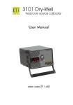
3000 SERIES
DRY-BLOCK HEAT SOURCE
USER MANUAL
Please read this manual before switching the unit on
IMPORTANT safety information inside
1. INTRODUCTION
TABLE OF CONTENTS
1 INTRODUCTION 1
2 SAFETY 2
3 OPERATION 3.1 Parts and Controls
3.1.1 Power Lead
3.1.2 Power Switch
3.1.3 Fan
3.1.4 Stand
3.1.5 Dry-Block
3.1.6 Temperature Controller
3.2 Operation
3.2.1 Dry-Block Set-Up
3.2.2 Temperature Setting
3.2.3 Probe Testing
3.2.4 Display Units
3
3
3
3
3
3
3
3
4
4
4
5
5
4 MAINTENANCE 4.1 Care of the 3000 Series Units 4.2 Warranty 6
6
6
5 SPECIFICATIONS 7
The 3000 Series dry-block heating and cooling sources allow
users to check the accuracy of thermometers and sensors
as a system, on site, without the need for heavy, expensive
equipment. The dry-blocks are high accuracy portable
temperature sources that are extremely easy to use. Simply
plug in, switch on and set the dry-block to the temperature
that you wish to check, insert your probe into the well and
take the reading. Compare the temperature reading of your
thermometer and probe to the displayed temperature of the
dry-block and the difference is the error of your instrument.
For optimum accuracy and NIST traceability use a reference
thermometer to make comparison measurements.
The 3000 Series dry-blocks are controlled by a closed loop
microprocessor based digital PID temperature controller
system incorporating a combination heater/cooler and a
precision platinum RTD sensor housed in the aluminum
block. Fan cooling allows rapid changes in block temperature
upon demand. The required temperature may be adjusted
in 0.1° increments across the range of the instrument using
the buttons on the front panel. These units are ideal for use
in a variety of industrial and process applications. Each
unit is supplied with a traceable certificate of calibration
showing actual test data, which can be used as part of quality
assurance programs.
1
2 SAFETY
Operate dry-blocks in an ambient temperature between
+50°F and 86°F (+10 and +30°C) (+15 to +25°C for optimum
accuracy) and humidity between 5 to 95% (non condensing).
Note: High humidity will cause icing of the well when operated
below zero. The fan runs continuously to moderate the
internal unit temperature. Always ensure the air vents and
fan aperture are clear and have at least 6 inches (150mm) of
space between them and any obstructions. NEVER cover the
unit while in operation or operate if the fan stops.
The calibrator can operate at high and low temperatures.
Precautions MUST be taken to prevent personal injury or
damage to surrounding objects. Probes may be hot or cold
when removed from the unit and should be placed on a heat
resistant surface and handled with care. The unit may remain
hot for several minutes after switching off. DO NOT switch off
at temperatures above +212°F (+100°C). Allow to cool before
storage.
Care must be taken when removing probes and inserts from
the units. If the unit is set at a high temperature the inserts
will be very hot and could cause burns to the hands. Please
use the insert removal tool supplied. After removal place hot
probes and inserts only on a suitable heatproof surface.
Only place temperature probes in dry-block holes. These units
are designed to be operated dry. DO NOT introduce any liquid
into any of the dry-block holes.
These dry-blocks are designed to be rugged and durable
but contain electronics. DO NOT operate in dirty, dusty or
very damp environments or near liquids that could present a
hazard from electric shock.
Connect input power lead to only a 110-115V or 230 V, 50-60
Hz (model dependant) grounded AC power supply. The unit
requires up to 200 watts of power.
3000 Series dry-block heat sources are programmed and
calibrated at the factory for optimum performance and should
not need adjusting. If the unit is out of calibration or is in need
of repair please return to the supplier. The dry-block unit
is equipped with an internal electrical fuse. If a fuse blows,
return to the supplier for inspection and repair. THERE ARE
NO USER SERVICEABLE PARTS INSIDE.
2
3 OPERATION
3.1 Parts and Controls
3.1.1 AC Power
The power cord is clamped through the rear panel of the unit
and is not removable. Plug into a standard 110-115V or 230 V
(model dependant) grounded power outlet socket.
3.1.2 Power Switch
The power switch is located on the rear panel of the unit and
is indicated with a 1 and a 0.
3.1.3 Fan
The internal fan runs continuously when the unit is operating.
This provides cooling for the internal electronic components.
Allow at least 6 inches (150mm) of space in front and behind
the unit and DO NOT obstruct any of the ventilation holes.
3.1.4 Stand
The stand can be folded flat against the under side of the unit
when not in use or if the unit is to be operated in a horizontal
position. It can be swung down and forward until it hits the
stops so that the unit can be used in an inclined position. The
stand was not designed to be a carrying handle and should
NOT be forced past the stops for this purpose.
3.1.5 Dry-Block
The aluminum Dry-Block is located on the right hand side of
the front panel. Dry-Well models have blocks with holes in to
accept temperature probes.
Model3 004: Inserts are available to suit standard probe
diameters. Use the nearest, larger size insert to probe
diameter being checked. The inserts are a close fit in the dryblock to give good thermal conduction. Keep the inserts clean
and avoid damage by storing carefully. The inserts MUST be
regularly removed and cleaned to ensure they do not seize
in the dry-block. DO NOT introduce any liquids or substance
into the dry-block or inserts as this may result in the inserts
sticking in the dry-block.
3.1.6 Temperature Controller
In normal operating mode the numeric LED display shows the
actual block temperature. A Control Output Indicator light is
located in the top left corner of the display. This indicates the
on/off state of the heater element in the block.
3
To show the set point temperature in the display press and
release either the up or down arrow button [up/down ill]. Press
and hold either the up or down arrow button [up/dn ill] to
change the set-point value.
A shift can be entered into the controller by pressing the
scroll (left-hand) button. Press and hold either the up or down
arrow button [up/dn ill] to change the shift value. A factory set
value will be entered at the time of certification. The shift value
should only be adjusted if the unit is being monitored by a
precision reference thermometer.
All other functions of the controller have been factory set and
locked to maintain accuracy and repeatability.
3.2 Operation
3.2.1 Dry-Block Set-Up
Place the dry-block unit on a flat level surface with at least 6
inches (150mm) of space in front and behind. The stand may
be swung out to lift the front of the unit. Plug the power cord
into a suitable grounded AC power outlet socket. Check for
and remove any foreign objects prior to switching on. Turn
the instrument on using the switch located on the rear panel,
below the power cord. The fan will start immediately and the
controller display will illuminate after approximately three
seconds.
3.2.3 Probe Testing
Insert the probe to be tested into one of the holes in the DryBlock. The probe should be a snug fit for good heat transfer
but should not be so tight that it cannot be removed easily.
Best results will be obtained when the probe is inserted to
the full depth of the Dry-Block hole of closest size to the
probe diameter. Allow the reading from the probe to stabilize
and then compare the reading with either the temperature
controller display or an external reference thermometer. For
optimum accuracy use a high precision reference thermometer
and probe. If probes with a large mass are inserted into the
Dry-Block holes the unit will require up to 10 to 15 minutes to
re-stabilize.
3.2.4 Display Units
The dry-block is shipped from the factory with display units
set to °F or °C. This can be reset at the factory. Call for
details.
3.2.2 Temperature Setting
The dry block may be set to any temperature between +91°F
and 572°F (+33 and +300°C) in 0.1° increments (see 3.1.6
Temperature Controller for details). The control will cause the
unit to heat or cool to the set point temperature. A control
indicator light will show in the top left corner of the display
when the heater is active. The dry-Block temperature is
displayed in operation. A small overshoot and undershoot
will occur when the block reaches the set point temperature.
Ten minutes is normally required to reach a higher set point
temperature. It will take longer to reach a lower set point
temperature. Once the set point temperature is reached
a further 10 minutes should be allowed for stability to be
achieved. For optimum accuracy and stability allow the unit to
warm up for 30 minutes after power up. The displayed block
temperature should stay within ±0.9°F (±0.5°C) of the set point
temperature.
4
5
4 MAINTENANCE
4.1 Care of the 3000 Series Units
3000 Series Dry-Block units require very little maintenance.
Avoid operation in dusty, dirty, oily or wet environment. If the
case becomes dirty it may be cleaned using a damp cloth and
mild detergent. Do not allow moisture to enter the case. It is
important to check for and remove any foreign objects in the
Dry-Block holes.
5 SPECIFICATIONS
Range:
+91.4°F to 572°F (+33 to +300°C) (at +68°F (+20°C)
ambient)
Resolution:
0.1° C/F
Accuracy:
±0.9°F:+91.4°F to +391.8°F
(±0.5°C: +33 to +199.9°C)
±1.8°F:+392°F to 572°F
(± 1°C:+200 to +300°C)
±3.6°F (±2.0°C) holes greater than 6.35mm
Resolution:
0.1° C/F
Heating Times:
Ambient to +572°F (+300°C): 10 minutes
Stabilization:
5 minutes
Cooling Times:
+572 to +212°F (+300 to +100°C): 15 minutes
Hole Dimension:
3001
2x 1/8" (3.3mm); 1x 5/32" (4.0mm), 3/16" (4.76mm), 1/4"
(6.35mm)
Hole Dimension:
3002:
1x 1/8" (3.3mm), 3/16" (4.76mm), 1/4" (6.35mm), 3/8"
(9.6mm)
Hole Dimension:
3003:
1x 3/16" (4.76mm), 1/2" (12.7mm)
Hole Dimension:
3004:
1x 1/8" (3.3mm); .51" (13mm) removable brass insert
Brass inserts available: 1/8" (3.3mm), 5/32" (4.1mm), 3/16"
(4.8mm), 1/4" (6.4mm), 3/8" (9.6mm)
Well:
Depth 4" (100mm)
Power:
110-115V or 230 volt AC 50-60 Hz 200 watt
Display:
0.4" (10.0mm) LED
Case
Dimensions:
4.1" x 6" x 7.3" (106 x 152 x 186mm) (HxWxD)
Weight:
3.9lbs. (1800 grams)
WARNING:
Never introduce any fluids or other foreign material into the
Dry-Block. This will damage the Dry-Block and could cause
probes to become stuck. It could also cause a potential
electric shock hazard. In the event that the heat source should
require service or repair, please contact the manufacturer for
assistance. There are no user serviceable parts inside and any
attempted repair will void any warranty.
4.2 Warranty
This instrument carries a twelve-month warranty and
guarantee against defects in either components or
workmanship. During this period, products that prove to
be defective will, at the discretion of ThermoWorks, be
either repaired or replaced without charge. The product
warranty and guarantee does not cover damage caused by
fair wear and tear, abnormal storage conditions, incorrect
use, accidental misuse, abuse, neglect, misapplication
or modification, or use with non-ThermoWorks hardware/
software. No warranty of fitness for a particular purpose is
offered and the user assumes the entire risk of using the
product. Any liability by ThermoWorks is limited only to the
replacement of defective materials or workmanship, and
ThermoWorks accepts no responsibility for consequential
loss. In line with our policy of continuous development, we
reserve the right to amend our product specification without
prior notice.
*Please note: Hole dimensions given are nominal
Certificate: This instrument has been checked or calibrated against reference
instrument(s) calibrated by a UKAS Accredited Calibration Laboratory at 122.2°F
(+50°C), 212°F (+100°C) and 302°F (+150°C).
6
7
Notes
Manufactured for
ThermoWorks, Inc
Phone: (801) 756-7705
Fax: (801) 756-8948
E-mail: [email protected]
Web: www.thermoworks.com
8
9