1
BABUC ABC
OPERATING MANUAL
Version 5.02 Eng/ 5.02/A22
Update March 2008
COD. MW6060
Table of Contents
1. GENERAL DESCRIPTION..............................................................................................7
1.1. OVERVIEW .......................................................................................................................................................... 7
1.1.1. Introduction ...................................................................................................................................................... 7
1.1.2. Models .............................................................................................................................................................. 7
1.1.3. Technical specifications ................................................................................................................................... 8
1.1.4. Panel description .............................................................................................................................................. 9
1.1.5. Power supply, protections, galvanic separation.............................................................................................. 10
1.1.6. Use of keyboard.............................................................................................................................................. 10
1.1.7. Use of the alpha-numeric keyboard................................................................................................................ 10
1.2. DATA ACQUISITION........................................................................................................................................ 11
1.2.1. Input types ...................................................................................................................................................... 11
1.2.2. Data acquisition rate ....................................................................................................................................... 11
1.2.3. Sensor power supply....................................................................................................................................... 11
1.2.4. Sensor error correction and validation of input data ...................................................................................... 11
1.2.5. Primary quantities and derivatives.................................................................................................................. 11
1.2.6. Automatic survey suspension in low energy situations .................................................................................. 11
1.3. STATISTICAL CALCULATIONS ................................................................................................................... 12
1.3.1. Calculation types ............................................................................................................................................ 12
1.3.2. Calculation time interval base ........................................................................................................................ 12
1.4. EVENTS ............................................................................................................................................................... 13
1.4.1. Event types ..................................................................................................................................................... 13
1.4.2. Operator messages.......................................................................................................................................... 13
1.5. RESULT AND EVENT STORAGE .................................................................................................................. 13
1.5.1. The survey file, support and memory structure .............................................................................................. 13
1.5.2. BABUC ABC data memory occupied by calculations (in bytes)................................................................... 14
1.6. ACTUATORS ...................................................................................................................................................... 15
1.6.1. Actuator equipment and their logics............................................................................................................... 15
1.6.2. Programmable logic actuators ........................................................................................................................ 16
1.6.3. Needed operative codes for actuator logics .................................................................................................... 16
1.6.4. Displaying and modifying actuator status ...................................................................................................... 17
2. INSTRUMENT INSTALLATION ....................................................................................18
2.1. MECHANICAL MOUNTING ........................................................................................................................... 18
2.1.1. Mounting on 50 mm diam. pole ..................................................................................................................... 18
2.1.2. Wall mounting ................................................................................................................................................ 18
2.2. ELECTRICAL CONNECTIONS ...................................................................................................................... 19
2.2.1. Input connections............................................................................................................................................ 19
2.2.2. Connection of the inputs of non LSI-LASTEM probes.................................................................................. 20
2.2.3. Power connection ........................................................................................................................................... 20
2.2.4. Serial lines connection.................................................................................................................................... 21
2.2.5. Actuator connections ...................................................................................................................................... 21
CORDLESS COMMUNICATORS INSTALLATION........................................................................................... 22
2.2.6. Site features .................................................................................................................................................... 22
2.2.7. Setup the communication parameters ............................................................................................................. 22
2.2.8. Sensibility calibration ..................................................................................................................................... 22
3. INSTRUMENT PROGRAMMING ..................................................................................24
2
MANUALE BABUC-ABC
3.1. How to start up the instrument and begin to use it rapidly............................................................................. 24
3.2. Factory programming ......................................................................................................................................... 25
3.2.1. Factory configuration for 5 inputs BABUC ABC versions............................................................................ 25
3.2.2. Factory configuration for 10 inputs BABUC ABC versions.......................................................................... 25
3.2.3. Factory configuration for over 10 inputs BABUC ABC versions:................................................................. 26
3.2.4. Alphabetic list of programmable functions .................................................................................................... 26
3.3. PROGRAMMING QUANTITY RELATED FUNCTIONS............................................................................ 28
3.3.1. Acquisition rate modification ......................................................................................................................... 28
3.3.2. Advance powering of sensors with respect to acquisition.............................................................................. 30
3.3.3. Engineering unit modification ........................................................................................................................ 30
3.4. PROGRAMMING PHYSICAL INPUT RELATED FUNCTIONS .......................................................... 31
3.4.1. Input assignment and sensor error corrections ............................................................................................... 31
3.4.2. Actuator assignment ....................................................................................................................................... 31
3.4.3. Derivated quantities set-up ............................................................................................................................. 32
3.4.4. Setup of the derived quantity “Wind Direction” ............................................................................................ 32
3.4.5. Solar radiometers configuration ..................................................................................................................... 33
3.4.6. Atmospheric barometer CX111P (DQA240) configuration.......................................................................... 33
3.5. PROGRAMMING TRANSMISSION PARAMETERS .................................................................................. 34
3.5.1. Tx/Rx status display ....................................................................................................................................... 34
3.5.2. Transmission speed (Bit rate) ......................................................................................................................... 34
3.5.3. Network protocol identifier ............................................................................................................................ 34
3.5.4. Data packet sizes ............................................................................................................................................ 34
3.5.5. Protocol types ................................................................................................................................................. 35
3.5.6. RTS signal advance switch-on ....................................................................................................................... 35
3.5.7. Including two-point or multiple line drivers................................................................................................... 35
3.5.8. Modem start-up............................................................................................................................................... 35
3.5.9. Lastem modem configuration instructions ..................................................................................................... 36
3.6. PROGRAMMING GENERIC PARAMETERS .............................................................................................. 37
3.6.1. System date/hour specification ....................................................................................................................... 37
3.6.2. Check available memory ................................................................................................................................ 37
3.6.3. Check battery power level .............................................................................................................................. 37
3.6.4. Error display ................................................................................................................................................... 37
3.6.5. Display IPC activity........................................................................................................................................ 37
3.6.6. "Beeper" specification .................................................................................................................................... 37
3.6.7. Keyboard security password........................................................................................................................... 37
3.6.8. Display's auto switch-off specification........................................................................................................... 37
3.6.9. Display version and serial number ................................................................................................................. 38
3.7. PROGRAMMING PARAMETERS IN SYSTEM MENU.............................................................................. 39
3.7.1. Displaying and editing operating codes for quantities.................................................................................... 39
3.7.2. Configuration of inputs................................................................................................................................... 39
3.7.3. Configuration of actuators .............................................................................................................................. 39
3.7.4. Circuit calibration ........................................................................................................................................... 39
3.7.5. "Standard quantities" specification................................................................................................................. 39
3.7.6. Linear or circular storage mode specification................................................................................................. 40
3.7.7. Selection of battery type ................................................................................................................................. 40
3.7.8. Formatting E2Prom configuration memory ................................................................................................... 40
3.7.9. Test instrument memories............................................................................................................................... 40
3.7.10. Restore survey .............................................................................................................................................. 40
3.7.11. Test writing in data memory......................................................................................................................... 40
3.7.12. Type of actuation .......................................................................................................................................... 40
3.7.13. Version/serial number................................................................................................................................... 40
3.7.14. Edit user’s serial number for instrument ...................................................................................................... 40
4. PERFORMING A SURVEY ...........................................................................................41
3
MANUALE BABUC-ABC
4.1. SURVEY START AND CLOSURE .................................................................................................................. 41
4.1.1. Survey programming ...................................................................................................................................... 41
4.1.2. Survey start..................................................................................................................................................... 41
4.1.3. Survey termination ......................................................................................................................................... 41
4.2. SCREEN DISPLAYS DURING SURVEY........................................................................................................ 42
4.2.1. Data display and standard quantities .............................................................................................................. 42
4.2.2. Displaying input configuration....................................................................................................................... 42
4.2.3. Actuator management..................................................................................................................................... 42
4.2.4. Communications ............................................................................................................................................. 42
4.2.5. Utilities ........................................................................................................................................................... 42
4.3. OPERATOR MESSAGE INSERTION DURING SURVEY .......................................................................... 42
4.4. USING THE MEMOCARD ............................................................................................................................... 43
4.4.1. Formatting the memocard............................................................................................................................... 43
4.4.2. Substituting the memocard ............................................................................................................................. 43
5. LOCAL FILE MANAGEMENT.......................................................................................44
5.1. FILE DISPLAY ................................................................................................................................................... 44
5.1.1. Display available memory .............................................................................................................................. 44
5.1.2. Display index of stored surveys...................................................................................................................... 44
5.1.3. Display the storage measurements into the memory ...................................................................................... 44
5.2. FILE CANCELLATION .................................................................................................................................... 44
5.2.1. Cancel last survey or all surveys in memory .................................................................................................. 44
5.2.2. Format memory .............................................................................................................................................. 44
6. DATA TRANSFER TO PC ............................................................................................45
7. PRINT OUT ...................................................................................................................45
7.1. Printing types ....................................................................................................................................................... 45
7.1.1. Printout of current input and actuator configuration ...................................................................................... 45
7.1.2. Instantaneous values ....................................................................................................................................... 45
8. PROGRAM MENUS ......................................................................................................46
8.1. SURVEY............................................................................................................................................................... 46
8.1.1. START SURVEY .......................................................................................................................................... 46
8.1.2. SURVEY SETUP .......................................................................................................................................... 49
8.2. FILES MANAGEMENT .................................................................................................................................... 50
8.2.1. Display memory availability........................................................................................................................... 50
8.2.2. Display list of surveys into memory card (pages) .......................................................................................... 50
8.2.3. Display stored elaborations in memory .......................................................................................................... 50
8.2.4. Delete last survey or all survey:...................................................................................................................... 50
8.3. SERIAL LINES ................................................................................................................................................... 51
8.3.1. COM 1 ............................................................................................................................................................ 51
8.3.2. COM 2 ............................................................................................................................................................ 51
8.3.3. Tx/Rx serial lines activity............................................................................................................................... 51
8.3.4. Speed transmission setup................................................................................................................................ 51
8.3.5. Address setup (in case of stations network) ................................................................................................... 51
8.3.6. Communication TX frame size selection:....................................................................................................... 51
8.3.7. Setup of the kind of use for the communication of Com 1:............................................................................ 51
8.3.8. RTS time selection.......................................................................................................................................... 52
4
MANUALE BABUC-ABC
8.3.9. Line driver use................................................................................................................................................ 52
8.3.10. Modem of type.............................................................................................................................................. 52
8.3.11. Setup of the kind of use for the communication of Com 2........................................................................... 52
8.3.12. LOCAL PRINT-OUT................................................................................................................................... 53
8.3.13. Enable Com 2 to print out instantaneous values........................................................................................... 53
8.3.14. Select the number or rows printed for each sheet (form feed)...................................................................... 53
8.4. CHANGE MEMORY CARD ............................................................................................................................. 54
8.4.1. Extraction phase ............................................................................................................................................. 54
8.4.2. Insertion phase................................................................................................................................................ 54
8.5. UTILITIES........................................................................................................................................................... 55
8.5.1. Day/time of the Internal watch modification .................................................................................................. 55
8.5.2. Battery voltage check ..................................................................................................................................... 55
8.5.3. Display of error type (if ERROR message flash) ........................................................................................... 55
8.5.4. Battery probe status ........................................................................................................................................ 55
8.5.5. Sound beeper activation/disactivation ............................................................................................................ 55
8.5.6. Keyboard protection by mean password......................................................................................................... 55
8.5.7. Insertion of display auto switch-off time after last button push ..................................................................... 56
8.5.8. Serial number and program version display ................................................................................................... 56
8.6. SYSTEM............................................................................................................................................................... 57
8.6.1. Operative codes modification ......................................................................................................................... 57
8.6.2. Inputs configuration........................................................................................................................................ 58
8.6.3. Actuator configuration.................................................................................................................................... 61
8.6.4. Setup standard quantities ................................................................................................................................ 63
8.6.5. Storage type setup........................................................................................................................................... 64
8.6.6. Survey recovery.............................................................................................................................................. 64
8.6.7. Selecting actuator operating logic .................................................................................................................. 64
8.6.8. Displaying resident program version and instrument serial number .............................................................. 64
8.6.9. Changing the user’s serial number ................................................................................................................. 64
9. FAULT DETECTION & CHECKING..............................................................................65
9.1. INTRODUCTION ............................................................................................................................................... 65
9.1.1. Battery voltage................................................................................................................................................ 65
9.1.2. Available memory .......................................................................................................................................... 65
9.1.3. External power supply test ............................................................................................................................. 65
9.1.4. Memocard and internal RAM memory test .................................................................................................... 65
10. CALCULATION DESCRIPTION..................................................................................66
11. ERROR MESSAGES...................................................................................................68
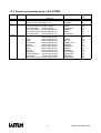
12. OPERATIVE CODES TABLE FOR LSI-LASTEM PROBES.......................................70
12.1. LSI-LASTEM Sensors ...................................................................................................................................... 70
12.2. Sensor not developped by LSI-LASTEM ....................................................................................................... 74
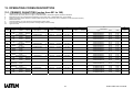
13. OPERATING CODES DESCRIPTION ........................................................................75
13.1. PRIMARY QUANTITIES (codes from 001 to 149) ....................................................................................... 75
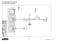
14. Drawings and schemes .............................................................................................85
5
MANUALE BABUC-ABC
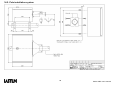
14.1. Installation with plinth...................................................................................................................................... 85
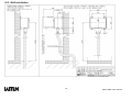
14.2. Pole installation system ..................................................................................................................................... 86
14.3. Wall installation................................................................................................................................................. 87
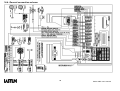
14.4. General connection scheme............................................................................................................................... 88
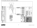
14.5. Connection scheme for combined probe DNA021 .......................................................................................... 89
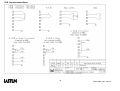
14.6. Input connections............................................................................................................................................... 90
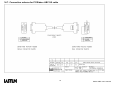
14.7. Connection scheme for PC/Babuc ABC 9/9 cable........................................................................................... 91
14.8. Connection schema with line driver................................................................................................................. 92
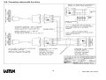
14.9. Connection schema with cordless adapters ..................................................................................................... 93
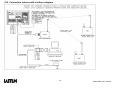
14.10. Connection schema with RS485 devices ........................................................................................................ 94
6
MANUALE BABUC-ABC
1. GENERAL DESCRIPTION
1.1. OVERVIEW
1.1.1. Introduction
BABUC ABC is a line of high technology instruments for the acquisition, processing, registration and
transmission of meteoclimatologic and environmental measurements prevalently for the field environment. Its
specific characteristics allow all data and event acquisition requirements to be met.
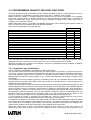
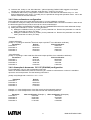
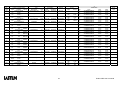
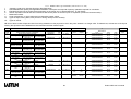
1.1.2. Models
Code
DGB055
DGB058
DGB105
DGB106
DGB108
DGB205
DGB305
DGB109
DGB209
DGB309
DGB409
DGB609
DGB107
DGB207
DGB307
DGC010
Channels N°
N°
Analogue Pulse Tot. Serial Actuators
4
1
5
55
1+1
4
1
5
55
1+1
8
2
10
50
1+1
8
2
10
50
1+1
8
2
10
50
1+1
16
4
20
40
2+2
24
6
30
30
3+3
8
2
10
50
1+1
16
4
20
40
2+2
24
6
30
30
3+3
32
6
38
22
4+2
48
6
54
6
6
8
2
10
50
1+1
16
4
20
40
2+2
24
6
30
30
3+3
Memory card reader, power supply 220 Vac
7
Case
Dimension
300x200x150
radio+add.batt.. 400x420x200
300x200x150
radio+add.batt. 400x400x200
radio+add.batt. 400x420x200
radio+add.batt. 400x400x200
radio+add.batt. 400x400x200
Rack 19”
4 modules
Rack 19”
4 modules
Rack 19”
4 modules
Rack 19”
4 modules
Rack 19”
6 modules
Portable case 520x430x210
Portable case 520x430x210
Portable case 520x430x210
140x45x210
Case for
Construction
Polyurethane
Aluminium
Polyurethane
Polyurethane
Aluminium
Polyurethane
Polyurethane
Polyurethane
Polyurethane
Polyurethane
ABS
MANUALE BABUC-ABC
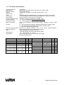
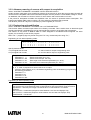
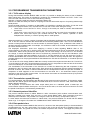
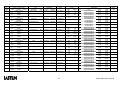
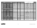
1.1.3. Technical specifications
Temporary Memory:
Mass Memory:
Data transmission:
Display:
A/D converter:
Clock:
Consumption:
Power supply:
Internal rechargeable batt.:
Actuated outputs:
Permanent outputs:
Electrical protection:
64 kB RAM
Models with removable memocard: sizes from 64 kB to 2 MB
RS-232 (RS-485 opt.)
LCD 80 char. (20char.x 4 lines) Min. operative temp. -10°C
15 bit
With dedicated rechargeable battery, 3 months life, accuracy 1 min./month
3.5mA (averaged over acquisition/processing/idle with display switched off)
24Vac (220Vac opt.) and 12Vdc or solar panel.
Standard: 12V Pb 2 Ah (optional: 7.2V NiCd 4 Ah)
10...14 Vdc unstabilized. Unit and total Imax: 0.25 A
10...14 Vdc unstabilized
Filters, gas dischargers, fuses on power supply; “transzorb” on inputs, serial
lines.
Housing:
a) Shock-resistant polyurethane, painted white RAL9003. Protection IP65
b) Die-cast aluminium, painted white RAL9003. Protection IP55
c) Shock-resistant black portable case
Galvanic isolation between Effected by inserting isolation units on the inputs; thermoresistance,
inputs and sensors:
thermocouple and Mv signal versions are available.
EMC
“Residential settings” emission EN 55022
“Industrial settings” immunity EN 50140 and 50204
Working limits:
-10°÷ +60°C (option –25°÷ +60°C)
Input signals:
Serial: acquisition from LSI sensors with serial output
Physical: see table below
Signal
Pt100 resistance
Pt100 resistance
Ni100 resistance
Linear resistance
TC-J
(auto. range change)
TC-K
(auto. range change)
TC-E
(auto. range change)
Range
-50°÷ +70 °C
-50°÷ +500°C
-50°÷ +70 °C
0 ÷ 2500 Ω
-50°÷ +350 °C
+350°÷ +600 °C
-200°÷ +500 °C
+500°÷ +1300 °C
-200°÷ + 280 °C
+280°÷ +1000 °C
Res.
0.02
0,1
0.02
0,5
0.15
2
0.2
3
0.1
2
Acc.
0.1
0,3
0.1
2
0.5
6
0.6
10
0.3
5
8
Signal
TC-T
TC-S
Linear mV
(auto. range change)
S1 thermistor
TTL impulses
Cold junction
Range
-200°÷ +200 °C
0°C÷+1600°C
-19 ÷ +19 mV
-300 ÷ +300 mV
0°÷ +44 °C
0 ÷ 65000
-50°÷ +70 °C
Res.
0.2
2
0.007
0.11
0.01
Acc.
0.6
6
0.02
0.4
0.1
0.05 0.4
MANUALE BABUC-ABC
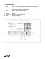
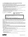
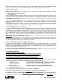
1.1.4. Panel description
1
2
3
Inputs:
Output terminal:
Switch:
4
5
6
7
8
9
10
11
12
13
Ground:
Ac main socket:
Dc socket:
Fuse:
Keyboard:
Power indicator:
Display:
Serial line:
Fastening:
Memocard:
N°1-8 for analogue inputs (7 contacts). N°9-10 for impulse inputs (4 contacts).
a) 12Vdc actuated (2 contacts), b) 12Vdc permanent (2 contacts).
Isolates equipment power feed from the internal battery. When the equipment is
switched off but an external power supply is present (mains ac, external battery, solar
panel), the internal battery remains under charge.
Socket on the instrument’s metal casing.
Socket for main power. Standard 24 Vca, optional 220 Vca.
Socket for solar panel or external 12V battery.
2 A if 24 Vac power supply, 0.5 A if power supply 220 Vca.
20 keys.
Only lit when external power is present.
80 (20x4) character LCD
Unified 9 pin connector.
Fastening screw for fixing instrument to case.
Memory card driver (64 kB ÷ 2 MB).
9
MANUALE BABUC-ABC
1.1.5. Power supply, protections, galvanic separation
BABUC ABC can be powered from the mains, by battery and solar panel. All standard models use
24Vac power supplies and are equipped with an internal 12Vdc 2Ah Pb battery; versions with
rechargeable 7.2V 4Ah NiCd battery is optional. Feeders 220/24Vac 50W (mod.DEA252) and 150W
(mod. DEA253) are available. Protection devices against electrical disturbances are inserted on the
power supply unit and on each input. These devices consist of filters, gas dischargers and zener diodes
and integrate those already present on many LASTEM sensors. Galvanic isolation units are also
available for sensors. Placed between input and sensor, variants are supplied for thermoresistances,
mV signals and thermocouple signals. The power autonomy depends on the data acquisition rate and
activator operations. In cases of external power blackout, the autonomy (without active actuators) is as
follows:
Battery type
Standard 2 Ah Pb battery
4 Ah Ni-Cd battery
Standard battery + external supplementary 15 Ah Pb battery
Standard battery + external supplementary 40 Ah Pb battery
* Continuous sensor acquisition rate, serial line switch-off
**Sensor acquisition rate greater than 1 minute, serial line switch-off
Fast rate*
1 day
2 days
8 days
20 days
Slow rate**
15 days
20 days
90 days
180 days
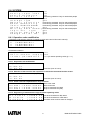
1.1.6. Use of keyboard
The keyboard contains 10 numeric keys and 10 function keys. The normal significance of the keys is as
follows.
Arrows
For data input screens, move the cursor one line at a time over the lines containing
data input fields. For menu screens, move the selection arrow from one option to
another (selection confirmed with "IMMIS"). For data display screens, perform single
line or continuous scrolling when the number of data lines exceeds the screen's
capacity.
Arrows
Move the cursor horizontally, one character at a time, through the data input field.
Within the field, cursor movement is circular and without limits. In certain screens the
format of displayed data changes.
pg
Move forwards and backwards a page in multi-page lists.
immis
Has the usual attributes of enter, confirmation, start-up.
esc
Exits the currently displayed screen and returns to the previously displayed one
(backtracking along the current branch path).
F2/-
Functions as a "PAUSE" key during the "Statistics display"; the display of statistical
data is temporarily blocked, but without affecting eventual registration of data.
Inserts the "-" sign when entering numeric data.
F1/,
Functions as a "RESET STATISTICS” key during the "Statistics display”. Inserts the
decimal point when entering numeric data.
On the display, there are ↑ ↓ when non-visible rows are available.
1.1.7. Use of the alpha-numeric keyboard
When the alphabetic part of the keyboard is needed, use the key where the request character is displayed.
Other symbols are available using the “0” key (0 = < > space +: , % / \ ( ) & ? ! ‘ *) or the “9” key (Y Z " 9 y
z @). Each alpha-numeric key may, if pressed repeatedly, be used to enter the number it represents, the
uppercase letter which appears on it, or the same letter in lowercase.
10
MANUALE BABUC-ABC
1.2. DATA ACQUISITION
1.2.1. Input types
The ABC data acquisition inputs are capable of receiving a wide range of signals, automatically adapting their
electronic circuits to the physical requirements of the signal from the sensor connected. The inputs are
individually configured for signal type and for the significance and processing to be assigned to the quantity.
The specified configuration is memorized until an eventual successive modification.
The instrument is able to acquire data from sensors with serial output; their connections happens through the
RS232 serial port. Babuc ABC manages both the quantities acquired from physical, analogue or pulse
sensors connected on its inputs and those acquired from the sensors connected on the serial port. These
sensors can be programmed through the Setup module of GAP package (see the GAP manual); the factory
configuration of Babuc ABC doesn’t contain any sensor with serial output.
1.2.2. Data acquisition rate
The data acquisition interval is programmable from 1 sec (0.5 sec/input true minimum scan) to 24 hr (for
processing periods in excess of 12 hours, the minimum data acquisition interval is 2 sec)
When feed probes are connected, the data acquisition rate could influences the battery life
(see §1.1.5. Power supply, protections, galvanic separation).
1.2.3. Sensor power supply
An un-stabilized 12Vdc output (unit and total Imax: 0.6 A) is associated with each input. This can be used for
sensors that require a power feed or auxiliary functions. The period for which this output can be activated in
advance of the acquisition is individually programmable for each type of quantity and is an integral part of the
operational functionality for the quantity itself.
1.2.4. Sensor error correction and validation of input data
The acquired data points, apart from specific range checks, are subjected to three categories of
programmable treatment, before being passed for further processing:
1) Sensor error correction: the eventual error of each sensor can be corrected by assignment of the values A
and B in the linear correction equation y = Ax + B.
2) Validation of each single data items before inserting them in the statistical calculations database; acquired
values are only inserted if they satisfy certain conditions:
a) a) The data item is invalid if the difference between it and the previous one acquired exceeds a
certain programmable level.
b) b) The data item is invalid if outside a range defined by two programmable values.
c) c) The data item is invalid if a different data item, for a another measurement of choice acquired in
the same cycle, is absent or invalid.
3) Validation of the data sets acquired in each statistical (processing base) for statistical processing and
successive recording of results:
d) statistical results are only recorded if the difference between the two extreme data points does not
exceed a specific programmed value.
e) statistical results are only recorded if the difference between the two extreme data points exceeds a
specific programmed value.
f) statistical results are only recorded if the number of valid data items acquired exceeds a programmed
percentage.
g) statistical results are recorded even if it is out from the validation parameters.
1.2.5. Primary quantities and derivatives
In addition to the primary quantities directly acquired from the sensors, BABUC ABC can also be programmed
to calculate numerous derived quantities, the factors of which can be based on other primary quantities, as
well as constants and standard quantities taken from a local library.
For example, the relative psychometric humidity is calculated via the acquisition of two temperatures (dry bulb
and damp bulb) and atmospheric pressure (standard quantity). To each primary quantity, five derivatives
quantities could be joint (not more than 80 primary plus derivatives quantities are managed on the system).
1.2.6. Automatic survey suspension in low energy situations
During a survey, should the instrument detect that its energy reserves have reached a critical level, it will
activate an automatic function for saving and suspending the survey. When the energy levels return to
predetermined levels, the programmed survey will be reactivated. (§3.6.3. Check battery power level).
11
MANUALE BABUC-ABC
1.3. STATISTICAL CALCULATIONS
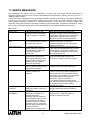
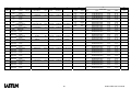
1.3.1. Calculation types
When the programmed time interval expires, the acquired data point sets are processed using the
programmed statistical mode.
A programmable period is associated with each time interval, indicating the terminal part of the interval whose
data is to be used for the calculations.
Up to 5 statistical and event processes can be assigned to each quantity (not more than 120 processes are
managed on the system):
Name
DTMinAveMaxStDvIst
MedDvSt
MinMedMaxDvSt
DTMinMaxTot
MinMaxTot
DTMinMax
MinMax
AveStDv
Ave
Tot
DurationMin
1Ist
10Ist
60Ist
Eolo0/1
Eolo0/16
Eolo0/18
Eolo0/32
Eolo0/36
Eolo1
Eolo2
Eolo3
Eolo4
Description
Average, Dated min, Dated Max, Standard deviation, Inst, Valid data %.
Average, Standard deviation, Valid data %.
Average, Minimum, Maximum, Std. deviation, Valid data % (Anadata Clima32
compatible)
Total, Dated min, Dated Max, Valid data %
Minimum, Maximum, Total.
Dated Min. Dated Max
Minimum, Maximum
Average, Standard deviation
Average
Total
Duration in minutes during the time interval
Instantaneous value at the start of the time interval
N° 10 equally distanced instantaneous values during the time interval.
N° 60 equally distanced instantaneous values during the time interval.
Percentage distribution of direction and speed in "6+calm" wind speed classes (0,3-2;
2-4; 4-6; 6-9; 9-12; >12 ms-1) and "1+calm" wind direction sectors. Average speed for
each direction sector and each speed class. The speed class delimiters and the “calm”
threshold value are programmable (into next version after 1.04).. This processing
produces the aeolian events table on the PC.
As for Eolo0/1 but with distribution over 16 wind direction sectors.
As for Eolo0/1 but with distribution over 18 wind direction sectors.
As for Eolo0/1 but with distribution over 32 wind direction sectors.
As for Eolo0/1 but with distribution over 36 wind direction sectors.
Aeolian analysis of the Prevailing Sector for which the amplitude, bisector, mean
weighted direction, standard deviation of direction and mean velocity are calculated. In
cases where a prevailing sector is absent, the mean velocity and standard deviation of
direction are calculated. The value of the calm threshold is programmable (default 0,3
m/sec.)
Resulting speeds and directions are expressed in modules and angle or sine and
cosine vectors. Direction standard deviation (Sigma Teta).
Hourly aeolian processing, compatible with the program Clima32 from Anadata data
logger on PC.
Daily eolian processing, compatible with the program Clima32 from Anadata data
logger on PC.
1.3.2. Calculation time interval base
The time intervals for the calculations, that is the frequency with which the latter are performed and
memorized can be assigned to groups of statistical calculations for each quantity. The last part (n) of the time
interval that is used in the calculations is also programmable; by default it corresponds to the interval itself, i.e.
all acquisitions made within the interval are processed. The time intervals run from 1 minute to 24 hours.
1
2
min(1)
hrs(n)
2
3
min(n)
hrs(n)
5
4
min(n)
hrs(n)
10
6
min(n)
hrs(n)
12
15
12
min(n)
hrs(n)
30
24
min(n)
hrs(n)
60 min(n)
free choice
MANUALE BABUC-ABC
1.4. EVENTS
1.4.1. Event types
It is possible to memorize events, the definitions of which have previously been programmed (example:
exceeding thresholds or gradients, concurrence of values) and impulsive events (example: rain trip or
passage of an object). Each event is defined by type, assigned value and the date/time of the occurrence and
is memorized in the same fashion.
Name
EvMin
EvMax
Description
Assigned lower threshold exceeded event
Assigned upper threshold exceeded event
Name
Description
EvDelta Assigned offset event
EvImp Impulse event
The choice of the event and calculation types with specification of the corresponding parameters, together
with the association of the chosen types with quantities operation codes can only be programmed on the PC.
The maximum number of programmable event and statistical calculation types for each quantity is five.
1.4.2. Operator messages
During a survey, the operator can specify and store messages of 19 characters, chosen from a menu made
on the PC via a specific function. The first message is empty, allowing it to be written and deleted directly from
the instrument's keyboard, pressing the corrisponding alphanumeric keys (§1.1.7. Use of the alpha-numeric
keyboard).
When a message is specified, it stored with a date/time tag. Example:
07/10/94 18:59:43;Clear sky
07/10/94 19:06:02;Light cloud
1.5. RESULT AND EVENT STORAGE
1.5.1. The survey file, support and memory structure
The Survey file is a temporary file, containing the data and the methods for interpreting it, acquired and
processed with the same method. Each survey file is composed of an identification number, a data
interpretation header and the data records (processed data, events and messages).
BABUC ABC has 64 kB of temporary RAM memory, where data is held if "mass" memory is not available.
The latter is a removable Memocard (in 64 kB to 2 MB formats).
BABUC ABC can use two memory types:
•
•
An internal RAM memory with 64kB size, used when the memocard in not inserted, where can be store
only one survey at a time. Without main power supply, the data in RAM are kept for about one month with
a rechargable internal battery. After this period the data in the RAM may be lost and is necessary to
reopen a new survey.
A removable memory card with size from 64kB to 2MB. On this memory support it’s possible to store more
than one survey. Anyway is advisable to limit the number of surveys to 10. While the memory card is
inserted the internal RAM is not used.
The data storage structure is programmable:
•
•
circular (when all available memory is occupied, newly acquired data is written over the oldest). This will
decrease the effective capacity of the memocard by a number of bytes equal to the size of the
measurement concerned.
linear (when all available BABUC ABC memory is occupied, further data is no longer accepted).
When using a Memocard, its removal does not suspend the storage of data in the temporary RAM memory;
when reinserted, the data accumulated in the meanwhile will be automatically transferred. Storage autonomy
is a function of the number of quantities involved, the number and type of calculations requested and the
specified time intervals.
When the memocard is not in, it is not possible to store more than one survey into the RAM memory and in
case of power supply breakdown or instrument shutdown the data are loose.
13
MANUALE BABUC-ABC
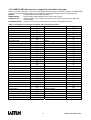
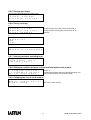
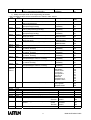
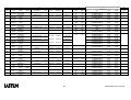
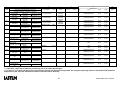
1.5.2. BABUC ABC data memory occupied by calculations (in bytes)
Certain structures, although not part of the calculation data structures, are anyway present in BABUC ABC
memory and must therefore be taken into consideration when determining the amount of free memory.
MemInf:
is always present at the start of memory.
RelMemHeader:
survey header, always present at the start of every survey.
ChMemHeader:
channel header, one for each active channel of the survey plus one; they follow the
survey header.
FinderMemHeader: present on every survey in the ratio of 1 for every 50 calculations stored.
Table of calculations and various structures with corresponding sizes:
Calculation/structure
Size in bytes
Calculation/structure
DTMinAveMaxStDvIstB
EOLO
0/36
21
DTMinAveMaxStDvtIstW
Eolo1
26
DTMinAveMaxStDvIstF
Eolo2
36
MinAveMaxStDvB
Eolo3
12
MinAveMaxStDvW
Eolo4
16
MinAveMaxStDvF
1IstB
24
DTMinMaxTotB
1IstW
19
DTMinMaxTotW
1IstF
22
DTMinMaxTotF
10IstB
28
MinMaxTotB
10IstW
11
MinMaxTotW
10IstF
14
MinMaxTotF
60IstB
20
DTMinMaxB
60IstW
18
DTMinMaxW
60IstF
20
DTMinMaxF
EvMinB
24
MinMaxB
EvMinW
10
MinMaxW
EvMinF
12
MinMaxF
EvMaxB
16
AveStDvB
EvMaxW
10
AveStDvW
EvMaxF
12
AveStDvF
EvDeltaB
16
AveB
EvDeltaW
9
AveW
EvDeltaF
10
AveF
EvPulseB
12
TotB
EvPulseW
9
TotW
EvPulseF
10
TotF
EvMessage
12
DurationMINB
MemInf
9
DurationMINW
RelMemHeader
10
DurationMINF
ChMemHeader
12
EOLO 0/1
FinderMemHeader
36
EOLO 0/16
246
EOLO 0/18
274
EOLO 0/32
470
14
Size in bytes
526
18
14
56
56
8
9
11
17
27
47
67
127
247
8
9
11
8
9
11
8
9
11
8
9
11
27
25
107
135
9
MANUALE BABUC-ABC
Example:
- n. 2 active channels (Temperature, TeGLOBOTERvn).
- calculations for both channels: DTMinAveMaxStDvIstW, AveStDvW.
- processing rate of 1 hour.
The memory requirement is given by summing:
- 1 MemInf (in the case of a first survey)
- 1 RelMemHeader
- 3 ChMemHeader (the two channels + 1)
- 4 calculations every hour (see calculation types for the two channels)
After 2 hour, the survey will have occupied the following memory space:
(MemInf )
(RelMemHeader)
(ChMemHeader x (two channels+1) = 135x3)
(Elaboration DTMinAveMaxStDvIstW x two channels x two hours = 26x2x2)
(Elaborazione AveDvstW x two channels x two hours = 12x2x2)
25
+
107 +
405 +
104 +
48
=
689 bytes.
1.6. ACTUATORS
1.6.1. Actuator equipment and their logics
The actuators (i.e. digital outputs) are useful when it is necessary, by means of BABUC ABC, to enable and
disable external systems according to programmable logic in relation to information available in the
instrument.
The actuators have 8..14 Vdc output, taken directly from the battery if it is the Pb type, or by means of a 12V
voltage booster if it is NiCd type; unit Imax 0.3 A, Itot 0.3 A. There is also an amplifier/contact insulator (code
DGD010) that can be installed in the back door of the instrument. With regard to programmability and
positions, the terminals are divided into two classes:
1) Actuators to feed the sensors.
There are 2 for each board with 8+2 inputs, one electrically common to all analog inputs, and the other to
all the pulse inputs. The latter will, if not used by the impulse probes, automatically become a “true”
actuator.
2) There are two “true” actuators used for various alarms and functions on each 8+2 input card §2.2.
ELECTRICAL CONNECTIONS:
• the first is always available on the panel connector which is marked, depending on the model of
acquisitition devices B1, D1, and F1 with terminals 1 (+) and 2 (-) (programmable from the keyboard
as outputs 1 (= B1), 3 (= D1), and 5 (= F1) respectively);
• the second, when not being used by the impulse inputs, is available on connectors 10 (= B2), 20 (= D2),
and 30 (= F2) on the marked panel, depending on the model of acquisition device, with terminals 4 (+)
and 3 (-) (programmable from the keyboard as outputs 2 (= B2), 4 (= D2), and 6 (= F2) respectively).
“True” actuators have two types of operating logic which may be selected from the appropriate menu in
“SYSTEM->ACTUATOR USE”:
• energy consumption logic: keeps the actuator turned off under regular operating conditions, and turns it
on only when there is an alarm;
• safety logic: keeps the actuator turned on under regular operating conditions, and turns it off when there
is an alarm or when the instrument is not working properly or it is broken.
Once the operating logic has been selected in actuator logic, the “ON” status is used when the output went to
the alarm conditions, and the “OFF” status is used when the output is remain under regular conditions.
The programmable types of actuator operating logic available in the current version are listed below. Actuator
outputs may be controlled by one or more of these types of logic, up to 8 types. If the actuator logics have an
output in common, the actuator output will be “ON” or have alarm status when any of the thresholds that have
been set is passed (and will not change status if any other thresholds belonging to other actuators are passed
thereafter). The actuator output will go “OFF” or be returned to normal status only when all of the values return
within the thresholds that have been set.
For technical reasons connected with the circuit, the response (status) of the actuator alarm when the
threshold is passed, may be delayed by ten to fifteen seconds to the acquisition of the signal. Intervention
times in the actuator logic should be programmed at 10 sec.
15
MANUALE BABUC-ABC
1.6.2. Programmable logic actuators
WIND ALARM: The actuator switches to "on" when the wind, coming from a certain directional arc with axis D
and amplitude L, has exceeded a threshold V1 for time t1; it returns to "off" when the wind speed drops below
a threshold V2 for time t2 or leaves the arc D(L) for time t2.
The values D, L, V1, t1, V2 and t2 are all programmable; it should be noted that when D is set to any value
and L = 360, this creates a condition that is independent from the direction. Physical absence or damage to
the direction sensor limits the parameters only to the speed value, while physical absence or damage to the
speed sensor locks the actuator in the off condition.
EVAPORIMETRIC PAN TOP UP: The electromagnetic valve to introduce water to top up the level in the
evaporimetric pan is opened at time H, only if the level is below LIV2, and is closed when it reaches LIV1; if
the level LIV1 is not reached, it is still closed after time t. The values H, LIV1, LIV2 and t are all programmable.
The physical absence or damage to the level sensor locks the actuator in the off condition.
PRECIPITATION START WARNING: The actuator switches to "on" when at least one of the following
conditions occurs: a) time t has elapsed from the start of precipitation; b) the quantity of rain PREC has fallen
from the beginning of the precipitation. The start of precipitation is identified by the first tilt of the pluviometer.
Resetting is performed after the RESET time from the last tilt. The values t, PREC and RESET are all
programmable. The physical absence or damage to the pulse sensor cannot be detected, while that of the
analog sensor locks the actuator in the off condition.
FLOOD WARNING: The actuator switches to "on" when a “PRECP” quantity of rain has fallen in a time never
interrupted by an absence of precipitation. The absence of precipitation period (Tap) is detected when, in this
time, the fell rain has not exceeded a minumum quantity defined by “precp”. The actuator return to "off”, and
the cycle start again, when an absence of precipitation period (as defined before) is detected, or when the
instrument is switched off, or for a manual reset by the operator.
GREATER THAN: The actuator switches to "on" after exceeding a maximum programmable value of a
parameter that can be selected among those configured. The actuator returns to "off" when the value is again
within its limits.
LESS THAN: The actuator switches to "on" after dropping below a minimum programmable value of a
parameter that can be selected among those configured. The actuator returns to "off" when the value is again
within its limits.
GREATER/LESS THAN: The actuator switches to "on" after exceeding a maximum programmable value (or
after dropping below a minimum programmable value), for one or more configured quantities of the same
programmable opcodee. The actuator returns to "off" when all the values are again in their limits.
TIMER: The actuator will periodically be turned “ON”, with programmable cycle duration and ”ON” duration.
The start of this function may also be programmed to start within 24 hours after the time of programming.
Greater than, Less than and Greater/Less than actuator logic permits selection of a single input or multiple
inputs with the same operating code, which may be selected from among those configured.
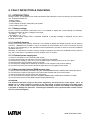
1.6.3. Needed operative codes for actuator logics
For activate the actuator logic is necessary to configurate the inputs with a suitable operative codes for their
algorithm. Following is a list of the needed operative codes for each selected logic.
WIND ALARM
Must be there two configured inputs:
• Angle with operative code selected from 034, 036.
• Wind Speed with operative code selected from 035, 040, 097, 101.
EVAPORIMETRIC PAN TOP UP:
Must be there one configured Level input with operative code selected from 060, 062, 063.
PRECIPITATION START WARNING and FLOOD WARNING
Must be there one configured Rain fall input with operative code selected from 046, 099, 102.
16
MANUALE BABUC-ABC
GREATER THAN, LESS THAN and GREATER/LESS THAN
Must be there one configured input with any operative code.
TIMER:
Can be programmed without reference to any operative code.
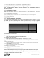
1.6.4. Displaying and modifying actuator status
If “ACTUATOR MANAGEMENT” is selected from the main menu during a survey, it will appears three
choices:
• “DISPLAY ALARMS ”: automatically enables display of a list of all inputs which triggered the alarm. If a
quantity is selected (by positioning the cursor on it and pressing enter), the actuator logic which triggered
the alarm will be displayed.
• “MODIFY CONFIG.”: if the number of the actuator logic to be modified is entered, it will be possible to
modify the parameters configured. When the modification is confirmed, the associated actuator output will
return to “OFF”; if ESC key is selected the actuators remain in the previous condition.
• “DISPLAY CONFIG.”: can be used to display, one by one, all the configured actuator logics.
17
MANUALE BABUC-ABC
2. INSTRUMENT INSTALLATION
2.1. MECHANICAL MOUNTING
2.1.1. Mounting on 50 mm diam. pole
With reference to the drawings at §14.1. Installation with plinth and §14.2. Pole installation system:
1) Create foundation for pole base. The pole can be anchored to the ground in two ways:
- A cement plinth on which a tripod, code DYA020, is fixed via expansion screws.
- A tripod, mod. DYA021, directly anchored to the ground with pickets.
2) Anchor the tripod and insert the pole.
3) Fix the instrument on the pole via two mounting collars.
The sensor cables enter the pole via the fair-leads and exit via the central union. The pole's outgoing cables
are inserted in a protective sheath that connects the central union to the instrument's cable input cone. The
mains power lead enters the pole through a slot near the pole's base or directly through the bottom of the
pole.
2.1.2. Wall mounting
With reference to the drawing at §14.3. Wall installation
1) Drill holes in the wall in correspondence to the 4 holes attached to the rear of the casing.
2) Fix the mounting brackets to the wall with expansion screws.
The cables must be inserted in a protective sheath that enters to the instrument's cable input cone. The mains
power lead must also be inserted in a protective sheath entering the cable input cone; the cable is then
plugged into the recessed female socket.
18
MANUALE BABUC-ABC
2.2. ELECTRICAL CONNECTIONS
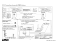
2.2.1. Input connections
Caution: always make electrical connections while the instrument is turned off.
Connect the sensors according to the programmed configuration and the setup table normally present on the
inside of the device lid. The current configuration can be printed (§7.1.1. Printout of current input and actuator
configuration) or displayed on the screen at any time.
With reference to the drawing at §14.6. Input connections:
7 contacts terminal block for analogue inputs (N°1-N°8; N°11-N°18; N°21-N°28):
o
1
+Current generator
o
2
+Analogue signal
o
3
-Analogue signal
o
4
Common current generator/analogue signal
o
5
+Actuated feed (12Vdc)
o
6
-Actuated feed (12Vdc)
o
7
Ground
For mA inputs the user should mount a 15 Ohm 0,1% resistance across terminals 2 and 3.
Three units of this resistance are available into the BABUC ABC fuse case
5 contacts terminal block for impulse inputs (N°9 and N°10 (B2); N°19 and N°20 (D2); N°29 and N°30 (D2)).
o
1
+Eventual 25mA photodiode feed
o
2
+Impulse signal
o
3
Common impulse signal/ photodiode feed/12Vdc actuated feed
o
4
+12Vdc actuated feed
o
5
Ground
2 contacts terminal block for actuators (B, D, F) and (A, C, E) for output power supply.
o
1
+ Actuation power supply (12 Vdc)
o
2
- Actuation power supply (12 Vdc)
ATTENTION:
The maximum and total charge on the power supplied by the terminals 5,6 of the inputs 1-8 is of
250mA. So, it is NOT possible to connect to the same block of inputs (according to the data logger
model: 1-5, 1-8, 11-18, 21-38, 41-48, 51-58) sensors that totally consume over 250mA. If this happens it
is possible to damage the transistor controlling the actuation of the input terminals and the sensors
won’t be powered anymore.
19
MANUALE BABUC-ABC
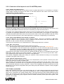
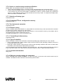
2.2.2. Connection of the inputs of non LSI-LASTEM probes
2.2.2.1. Probes with output tension
When the tension signal coming from any kind of sensor is greater than 300 mV, it is necessary to arrange a
voltage divider reducing the signal to this value. In the below table the ohm values of the most common
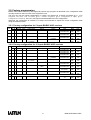
voltage dividers are directly supplied.
Table of the voltage dividers Ohm values for input signals:
Vin signal
0 ÷ 10 V
0÷5V
0 ÷ 2,5 V
0÷2V
0÷1V
0 ÷ 0,5 V
R1
32,3 kΩ
47 kΩ
22 kΩ
35,1 kΩ
23,3 kΩ
16 kΩ
R2
1 kΩ
3 kΩ
3 kΩ
6,2 kΩ
10 kΩ
24 kΩ
Connnect the voltage divider to the terminals of the interested input as per the scheme; if the sensor is not
powered by BabucABC the terminal 3 has to be connected by a jumper with the terminal 4.
The values of the voltage dividers resistors have to be the most possible precise, anyway it will be necessary
to calibrate the engineering parameters: set the value of end scale tension of the signal Vin. Read by the
voltmeter the tension value at the ends of R2; enter into the menu of the chosen operative code and modifiy
the value of the Param2i with the value read expressed in mV (see §3.3.3 Engineering unit modification)
2.2.2.2. Probe model HMP45CF from Vaisala or Campbell
The probe HMP45CF has a thermistor resistive sensitive element and can be connected to a BabucABC
applying a resistor of 3k3 Ω (precision 0,5%) in parallel to the two sensors wires and connected on the
terminals 1-2 and 3-4 of the connector of the desired input.
The sensors line resistance is not compensated for a cable length greater than 10 metres.
2.2.2.3. GILL sonic sensor
Babuc ABC can acquire data from the Gill sonic sensor in two ways:
• Connecting the current outputs of the sensor to the Babuc ABC inputs (see Sensor Manual)
• The connection of the Gill sensors has to take place by a 9 pins connector with the pins 5 and 9
connected by a jumper to the Babuc ABC serial port n.2. Leave the protocol default programming (Gill
format, Polar continuous),transmission 9600 bps, no parity, 8 data bit, 1 stop bit.
The Gill sensor, when there is no wind, does not calculate the direction that, so, is indicated as an error in the
Babuc ABC “Angle” channel. The channel “Direction” , anyway, shows in the correct way the value “Calm”.
The compatibility has been tested with a Gill sensor model WindSonic.
The channel configuration takes place setting the operative codes dedicated according to the acquisition
modalities. (vedi §Not Lastem Sensors).
2.2.2.4. Hydrolab multiparametric sensor
Babuc ABC can acquire instantaneous data from the multiparametric probe Hydrolab connecting the probe
serial to the serial port number 2 of Babuc ABC.
The connection of the Hydrolab sensor takes place through the cable given with the sensor, using a 9 pin
adaptor male/male. The sensor has to be programmed to generate data in spontaneous way in the format
TTY, transmission 9600 bps, no parity, 8 data bit, 1 stop bit. The compatibility has been checked with a model
Minisonde 4a. The channel configuration takes place setting the probe dedicated operative codes (vedi §Not
Lastem Sensors).
2.2.3. Power connection
Babuc ABC standard version has 24 Vac power supply, the “ac” power cable is plugged into the instrument's
socket. The circuit does not have a switch and is protected by a fuse. An additional external battery or solar
panel can be connected to the socket marked 12Vdc. If the instrument has a Nichel-cadmium(NiCd) internal
battery, the connection to the solar panel is direct (the solar panel mod. DYA202 can be used). If the internal
accumulator is a lead battery (Pb), a regulator must be inserted in between (a solar panel with regulator, code
DYA205, can be used).
20
MANUALE BABUC-ABC
2.2.4. Serial lines connection
The instrument has two RS232 serial lines. The RS232-1 (RS485-1) is dedicated to the connection to the PC;
the RS232-2 (RS485-2) is dedicated to the connection with local serial printer or with sensors with serial
output on RS232/RS485/radio line. For more information on the connection of this kind of sensors to the
Babuc ABC, refer to the relative manuals of installation and use or Sensor Manual.
The connector is a standard 9 pin one. For acting serial lines the user should short circuit pins 9 and 5 for
RS232-1 (RS485-1). In case of RS485 option, a 100 Ohm resistance should be mounted between terminals 4
and 7 of the input n.1 terminal
2.2.5. Actuator connections
The equipment to power via the actuator (digital output) is connected to the "B1", "B2", “D1”, “D2”, “F1”, “F2”
terminal pair, from where actuated 12Vdc is available as programmed.
21
MANUALE BABUC-ABC
CORDLESS COMMUNICATORS INSTALLATION
2.2.6.Site features
There are many consumer devices that are using a radio frequency in the same band of the cordless
communicators (433 MHz), and therefore they could cause trouble in the data transmissions. Fortunately
these devices has short transmission time and, usually, makes transmissions rarely. The transmission
protocol inside BABUC ABC adopt some solutions to limit the lost of data and, normally, the consumer’s
devices causes no problems.
To obtain a reliable data transmission it is better to avoid some installation situation, like these:
•
•
•
•
Near buildings with alarm/security devices connected to infrared sensor via radio
Industrial finding-people devices
Metallic obstacles and metallic grids with sweaters smaller than 1 meter causes screen to the
electromagnetic field
Via radio HI-FI audio devices
Warning: before to start any building and electric connection works is opportune audit that the site is suitable
for radio transmission in the 433 MHz band.
2.2.7. Setup the communication parameters
Setup or change in the Serial lines->Com 1 menu these parameters:
•
•
•
•
•
•
Identifier, if more than one station exists in the radio network (choose a different identifier for each station)
TX frame size = 256 byte
Bit rate = 9600 bps
Line driver = No
RTS anticipation = 0.1
Modem type = No modem
Follow the instructions on the GAP user guide for changing the transmission parameters on the PC.
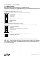
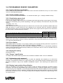
2.2.8. Sensibility calibration
After the setup of the communication parameters, is necessary to calibrate the sensibility of the radio receiver
device. Follow these steps:
1) Connect the cordless communicator DEC211 to the PC as reported in the §14.9. Unscrew and open the
frontal panel of the cordless communicator unit.
2) Start the Remote module of the GAP programs and setup 3 second in Option – Display update interval
menu. Start the communication between PC and BABUC ABC.
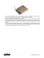
3) Adjust the receiver sensibility on the RTUN module, rotate the trimmer indicated in the next figure. To act
on the trimmer, it is necessary to have a very small screw driver, similar to the clockmakers' ones. The
sensitivity variation takes place rotating slightly and slowly the trimmer. Counterclockwise the sensitivity
raises (the farthest signals are received better), clockwise the sensitivity decreases (the immunity to
disturbs improves). Attention: do not change the position of the other trimmers; otherwise the working
characteristics of the radio module will be compromised. The factory setting is for the maximum sensibility
with the trimmer turned counterclockwise. If the green led (signal for data reception) is fix or it blinks
continuosly in a random way, it means that the receiver is too sensitive to the radio noises, then it is better
to decrease the sensibility turning the trimmer clockwise until the green led stop to blink. The red led
(signal for data transmission) should blink every about 3 seconds, showing the PC transmission.
22
MANUALE BABUC-ABC
4) If more than one BABUC ABC are in the radio network, start with the calibration on the farthest Babuc
ABC or on the instrument in the mostly adverse conditions (presence of obstacles).
5) Connect the cordless communicator DEC211 to the BABUC ABC as reported in the §14.9. Unscrew and
open the frontal panel of the cordless communicator unit.
6) Adjust the transmission increasing or decreasing the sensibility on the receiver until, after the green led
blinks, the red led blinks too. Red led indicates that BABUC ABC has recognized the message from PC
and respond with its data. In this condition the communicator connected to the BABUC ABC is correctly
adjusted.
7) Go back to the communicator connected to the PC and eventually adjust better the receiver sensibility
until the red and green leds blinks alternatively. At the end it will possible to run the BABUC ABC from the
PC by the Remote GAP module. Repeat these operations for all BABUC ABC in the radio network,
leaving unchanged the calibration in the communicator connected to the PC.
23
MANUALE BABUC-ABC
3. INSTRUMENT PROGRAMMING
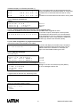
3.1. How to start up the instrument and begin to use it rapidly
These instructions will permit users to begin using the instrument within a short time period.
1. Installing the instrument: Perform mechanical and electrical assembly according to the instructions
provided in chapter 2.
2. Using the keyboard: It is useful to know how to use the various keys to perform the various menu
functions (§1.1.6. Use of keyboard).
3. Turning on the instrument: Press the On/Off switch on the panel underneath the keyboard, and wait until
the introductory screen comes up after the instrument has been initialised; then press ENTER to go to the
main menu. The most important programming features have already been set to default values which will
satisfy the requirements of most users. In this section we take only a brief look at the functions available;
we will later go into greater detail to find out more about the instrument’s potential.
By selecting the various menu functions, it is possible to display and edit initialisation parameters before
beginning a survey. These parameters include:
• Survey: to set up and start a survey.
• Turning off: useful for memorising all data and measurements which have been obtained before
the instrument is turned off with the On/Off switch.
• Archive management: controls availability, display and/or deletion of contents of the archive.
• Serial lines: checking and/or modification of communications parameters using serial transmission.
• Change Memocard: addition or removal of a memocard.
• Utilities: contains a scrolling menu of utility functions which are available and/or modifiable even
during a survey.
• System: contains a scrolling menu of functions which can be programmed before a survey.
4. Input configuration: The instrument is supplied with a factory configuration (§3.2. Factory programming). To
modify it directly on the instrument, go into the “SYSTEM” menu, reset it using “INPUT CONFIG.->RESET
ALL” and then follow the procedure for configuration of inputs and actuators (§3.4. PROGRAMMING
PHYSICAL INPUT RELATED FUNCTIONS). To modify configuration from a Pc, use the Setup program
(see GAP program).
5. Start survey: Select “SURVEY” from the main menu to begin taking measurements. A survey may be
programmed with a start and end date and time and a comment, or it may be started immediately and
ended manually.
6. Data acquisition and processing: When it starts a survey, the instrument begins performing a continuous
measurement cycle. It turns on the power supply to probes with a separate power supply in advance,
acquires the quantities configured with a sampling interval, checks whether these quantities fall within the
acceptable limits that have been set, and linearises and engineers them, depending on which physical
quantities are acquired (§3.3. PROGRAMMING QUANTITY RELATED FUNCTIONS). Instantaneous
values may be displayed using “DISPLAY DATA” and updated in real time each time they are acquired. All
values acquired are used to compile statistics, or records of events, for each of the configured quantities
(§1.3. STATISTICAL CALCULATIONS) and then memorised in the mass memory available (§1.5. RESULT
AND EVENT STORAGE). Processing times and types are programmed separately for each quantity and
may be modified only using the Setup program on the PC.
7. Reading and downloading reports: Reports may be downloaded from the BABUC ABC using the
appropriate Communication program (refer to GAP program), stored in the PC’s memory and displayed in
graphic or table form. The most common reports may be displayed on the BABUC ABC, using the function
in the “DISPLAY DATA->REPORTS” function.
8. Displaying various data: During a survey, it is possible to display and modify the date/time, beeper,
keyboard and display off parameters using the “UTILITIES” menu function.
9. Stop survey: To stop taking measurements, select “END OF SURVEY” and confirm the selection.
10.Turning off the instrument: Before turning off the instrument (On/Off switch), carry out the turning off
procedure by selecting the appropriate item in the menu; if this is not done, all the reports generated
during the measurement session will be lost.
24
MANUALE BABUC-ABC
3.2. Factory programming
BABUC ABC leaves the factory with a general purpose logic program as described in the configuration table
normally located on the inner face of the equipment cover.
The user can use the original configuration or modify it as desired via a specific procedure (§3.4.1. Input
assignment and sensor error corrections, §3.4.2. Actuator assignment, §3.7.2. Configuration of inputs, §3.7.3.
Configuration of actuators). The not in use inputs should be deleted from the configuration.
Whenever the configuration is modified, it is always recommended to reprint the current configuration table
using the relative function.
3.2.1. Factory configuration for 5 inputs BABUC ABC versions
Inp
N°
1
Characteristics
Corr
A B Opcode Rate
1 0
077
1'
Input signal
60÷300mV
Range
-30+70°C
Name
Temperature
2
1
0
031
1'
60÷300mV
0÷100%
Rel. Humidity
3
1
0
033
1'
0÷300mV
800÷1100 hPa
4
1
0
036
5"
Resistive
0..2 kohm
0÷360°<
Atmospheric
pressure
Wind direction
Elaborations
Base
AveMinMaxStDs
1h
AveMinMaxStDs
24h
AveMinMaxStDs
1h
AveMinMaxStDs
24h
AveMinMaxStDs
1h
AveMinMaxStDs
24h
1h
24h
Type
Port.
1h
24h
1h
24h
1h
24h
1h
24h
3.2.2. Factory configuration for 10 inputs BABUC ABC versions
Inp
N°
1
Characteristics
Corr
A B Opcode Rate
1 0
077
1'
Input signal
60÷300mV
Range
-30+70°C
Name
Temperature
2
1
0
031
1'
60÷300mV
0÷100%
Rel. Humidity
3
1
0
033
1'
0÷300mV
800÷1100 kPa
4
1
0
036
5"
0÷360°<
5
1
0
047
10"
Resistive
0÷2 kohm
0÷20mV
Atmospheric
pressure
Angle
0÷1500Wm-2
Global radiation
6
1
0
049
10"
-10+15mV
Net radiation
7
1
0
078
1'
100/200mV
-1000+1500
Wm-2
Yes/No
8
1
0
009
1'
Pt100
-30+70°C
Temperature
9
10
1
0
099
1'
Impulsive
Presence
Not programmed
0,2mm
Rain quantity
25
Elaborations
Base
AveMinMaxStDs
1h
AveMinMaxStDs
24h
AveMinMaxStDs
1h
AveMinMaxStDs
24h
AveMinMaxStDs
1h
AveMinMaxStDs
24h
1h
24h
AveMinMaxStDs
1h
AveMinMaxStDs
24h
AveMinMaxStDs
1h
AveMinMaxStDs
24h
DurationMin
1h
DurationMin
24h
AveMinMaxStDs
1h
AveMinMaxStDs
24h
Type
Tot
Tot
1h
24h
Port.
1h
24h
1h
24h
1h
24h
1h
24h
1h
24h
1h
24h
1h
24h
1h
24h
1h
24h
MANUALE BABUC-ABC
3.2.3. Factory configuration for over 10 inputs BABUC ABC versions:
First 10 inputs as 3.2.2, next not programmed.
Inp N°:
Corr.:
Opcodee:
Rate:
Input signal:
Range:
Name:
Type:
Base:
Port.:
Number of input.
Terms A and B used in the linear equation for sensor error correction (y=Ax+B).
Operation code of quantity in output. This sums all of the process operating modes
necessary to convert the sensor signal to the desired final quantity.
Scanning interval used by BABUC ABC for reading the sensor.
Type of sensor or electrical input signal.
Measurement range.
Name of quantity in output.
Type of calculated and stored results.
Periodic time interval over which data is acquired for calculations and result registration.
Final portion of the periodic interval effectively used.
3.2.4. Alphabetic list of programmable functions
Description
Acquisition unit electrical input signal (type and field)
Actuators (assignment)
Actuators (algorithm and logic of actuation)
Actuators (reset and configuration setup)
Actuation for external users
Battery (selection of Pb or NiCd)
Baud rate
Communications protocol (type)
Data storage format (byte, word, float)
Display (auto switch-off time after last key-press)
Data statistic (resetting)
Events (parameter specification)
Events (types for which registration is requested)
Input signal linearization
Inputs (assignement)
Instrument's user serial number (modifiable)
Keyboard (password access protection)
Keyboard beeper (enable, disable)
Line driver (setup)
Modem (modem type)
Operator messages (entry)
Operator messages (list preparation)
Protocol (network protocol identifier)
Quantity in output (descriptive name)
Quantity in output (number of decimal places)
Raw data acquisition rate
RTS (Request to send) for radio communication
Sensor error (correction)
Sensor power feed (in advance of data acquisition)
Standard quantity (specification)
Standard quantity (specification during the survey)
Statistical calculations
Survey (close)
Survey (programming and comment entry)
Survey (start)
Survey storage structure (linear or circular)
System date/time
Time base (terminal portion used for result calculations)
Time base for preselected processing
26
Executable on
BABUC
PC
*
*
*
*
*
*
*
*
*
*
*
*
*
*
*
*
*
*
*
*
*
*
*
*
*
*
*
*
*
*
*
*
*
*
*
*
*
*
*
*
*
*
*
*
*
*
*
*
*
*
*
See
§
3.3.3.
3.4.2.
1.6.4.
8.1.1.2.
1.6.1.
3.5.2.
3.5.5.
3.6.8.
3.4.1.
3.7.14.
3.6.7.
3.6.6.
3.5.7.
3.5.8.
4.3.
3.5.3.
3.3.1.
3.5.6.
3.4.1.
3.3.2.
3.7.5.
8.1.1.1.
4.1.3.
4.1.1.
4.1.2.
3.6.9.
3.6.1.
MANUALE BABUC-ABC
Transmission packet size (frame)
Validation checks for accepting database in statistical calculations
Validation checks for accepting raw data in the database
Wind calm (assignment of threshold)
Wind speed classes (assignment of class benchmarks)
For PC options see SW GAP User manual
27
*
*
*
*
*
*
3.5.4.
MANUALE BABUC-ABC
3.3. PROGRAMMING QUANTITY RELATED FUNCTIONS
The set of operational functions activated in order to obtain calculated results for a certain quantity from one or
more input signals is synthesized in a specific code, known as the "Operation code" (Codop).
BABUC ABC has a library of opcodes suitable for treating the most varied of quantities. If the operating
instructions contained within a chosen opcodee do not quite correspond to requirements, it is possible to
modify and adapt them. Some instructions are locally modifiable on BABUC ABC, whilst others can be
modified on PC. (See GAP manual).
BABUC ABC holds a library ("SYSTEM->LIST&MODIF.OPCODEE" menu) containing 200 operation codes, of
which 150 are for primary quantities and 50 for derived quantities.
The functions synthesised in the "Opcodee" are:
Executable on
Description
BABUC
PC
Sensor power feed (in advance of data acquisition)
*
*
Time base for pre-selected processing
*
Time base, terminal portion used for result calculations
*
Wind calm (threshold assignment)
*
Wind speed classes (assignment of class benchmarks)
*
Decimal places used for quantity values
*
Description of quantity in output
*
Statistical calculations (type and rate)
*
Events, types for which registration is requested
*
Engineering units for quantity in output
*
*
Validation checks for accepting raw data in the database
*
Validation checks for accepting database in statistical calculations
*
Input signal linearization
*
Raw data acquisition rate
*
*
Electrical/serial input signal to the acquisition unit (type and field)
*
From the initial menu, choose "SYSTEM->LIST&MODIF.OPCODEE". A list of the library's opcodes will be
displayed on the §12. OPERATIVE CODES TABLE FOR LSI-LASTEM PROBES of this manual).
Select the Opcodee of the quantity to be modified; a sub-menu of parameters directly modifiable on BABUC
ABC will be displayed for selection.
3.3.1. Acquisition rate modification
Select "SYSTEM->LIST&MODIF. OPCODEE->ACQUISITION RATE"
The acquisition rate is the interval of time between one data acquisition and another. The interval can be from
1 second to 12 hours. Correct setting of the acquisition rate permits a representative database to be built from
which valid statistical results may be calculated. It is advised however to balance the demand for a large
database against equipment energy savings; in fact, a faster data acquisition rate implies increased energy
consumption.
The instrument's maximum sampling speed is 2 channels per second; the acquisition times for each sensor
should therefore be chosen on the basis of the total number of connected sensors, so that enough time is
available to interrogate all of them.
When acquisition rates are near the maximum permitted values, the system preferentially acquires the first
channels programmed, but this does not preclude the acquisition of those that follow; this possibility depends
upon the system load (user interactions via keyboard or operations, data transmission, large variances in
sensor signals, etc.). When very fast channels (e.g. wind speed and direction) and slow channels (pressure,
air temperature, ground temperature, etc.) are used together, during the “INPUTS CONFIGURATION” it is
advised to insert the quantities with fast acquisition rates in the first channels and then the others; in this
manner, the system gives “preference” to the faster quantities with respect to the slower ones.
To verify whether a quantity is acquired at the specified rate, using the “DATA DISPLAY->STATISTICS”
option, check that the number of acquisitions made in a given period is as expected.
As regards the acquisition of LSI sensors with serial output, it is better to set the acquisition rate of the sensor
that corresponds to the acquisition rate indicated on the sensor. The instant of acquisition of Babuc ABC and
of the sensor are not necessarily synchronized; in this case the instrument could perform the reading of the
quantity with a maximum delay that corresponds to the acquisition time of the sensor.
Babuc ABC doesn’t give an error if the measure acquired from the sensor is wrong, but it uses for its
acquisition the last correct measure received. That happens to three consecutively wrong measures at the
28
MANUALE BABUC-ABC
maximum; so the fourth measure determines the effective message of error from the instrument, that persists
until it receives a new valid measure.
29
MANUALE BABUC-ABC
3.3.2. Advance powering of sensors with respect to acquisition
Select "SYSTEM->LIST&MODIF. OPCODEE->ANTIC.SENSOR SUPPLY"
Certain sensors need power to be supplied in advance of the moment in which they acquire data. Normally all
sensors that are amplified and/or have normalized outputs must be powered. The available voltage is 12Vdc,
un-stabilized, with a maximum current of 0.25 A for each sensor and a total maximum of 0.6 A.
If the power-on anticipation exceeds the acquisition rate, the sensor is powered without interruption. The
instant when BABUC ABC powers a sensor, all of the others are simultaneously powered.
The advance period can vary from 0 seconds (no power supplied) to 12 hours.
3.3.3. Engineering unit modification
Select "SYSTEM->LIST&MODIF. OPCODEE->IN->OUT PARAMETERS".
This function allows converter output values to be linearly converted. This is useful when an electrical signal
(usually normalized) is available that is to be read and directly stored in the quantity that it represents.
This function is only active on BABUC ABC for codes assigned to normalized electrical signals. For other
signals, it is necessary to use the PC program.
Note: The "-" (negative) sign may be set using the "F2/-" key; the decimal point using "F1/,".
Engineering of non-status operating codes:
P
P
P
P
a
a
a
a
r
r
r
r
a
a
a
a
m
m
m
m
1
2
1
2
i
i
o
o
Specify desired values
1i: input signal start of scale
2i: input signal end of scale
Example
Parameter 1i: 0
Parameter 2i: 300
Parameter 1u:-20
Parameter 2u:100
*
*
*
*
0
0
0
0
0
0
0
0
0
0
0
0
0
0
0
0
.
.
.
.
0
0
0
0
0
0
0
0
0
0
0
0
0
0
0
0
0
0
0
0
1u: start of scale for output in engineering units
2u: end of scale for output in engineering units
Electric scale start (es. 0 mV)
Electric scale end (es. 300 mV)
Start range of the measured parameter (es. -20°C)
End scale of the measured parameter (es. 100°C)
Example
2) A °F scale is required for a sensor with 0+70°C output.
Using the GAP software on PC, the desired engineering units are enabled by programming
the following parameters:
Parameter 1i: 0
Parameter 2i:70
Parameter 1u:32
Parameter 2u:158
Engineering of status operating codes:
Modification of limits on operating codes indicating status or presence (73, 78, 79, 80).
The operator may programme the limits on the interval for the logical status signal (maximum
amplitutde 0..+300 mV) and assign a threshold above or below which it is inverted.
Example:
OFF STATUS: + 00000.000 (accepts a value between 0 and 150 and displays NO).
ON STATUS: + 00300.000 (accepts a value between 150 and 300 and displays YES).
THRESHOLD: + 00150.000.
30
MANUALE BABUC-ABC
3.4. PROGRAMMING PHYSICAL INPUT RELATED FUNCTIONS
3.4.1. Input assignment and sensor error corrections
This function is used to assign the operation code or codes to each input for the quantities to acquired from
the sensors; eventual error correction factors for the sensor can be assigned. If all inputs are already
assigned, a warning is issued and it is necessary to free one with the "RESET" functions before continuing.
Select "SYSTEM"CONFIG INPUT CHANS" from the main menu and then:
- Select "CONFIG. VIEW" to display the current configuration.
- Select "SINGLE RESET" and specify number of the input for which the current assignment is to be
cancelled. Or
- Select "TOTAL RESET" to cancel all current input assignments.
- Select "CONFIGURE" to assign free input, or modify the sensor correction factors. Then:
- Insert the Operation Code (Opcodee) of the desired quantity.
- Insert the input number (INP.) to which the sensor is to be connected.
- Insert the factors A and B for the eventual correction of sensor errors, according to the equation y=Ax+B. If
the sensor is error-free, confirm the default values of A=1 and B=0.
Use the following formula to calculate A and B:
A:
Amplification
=(FS-IS)/(fs-is)
B: Offset
=[(ISxfs)-(FSxis)]/(fs-is)
is=
fs=
IS=
FS=
Start of scale value to be corrected
End of scale value to be corrected
Desired start of scale
Desired end of scale
Example 1
A sensor has an error of +2°C over its entire range (-30... +70°C).When the probe
signal 22°, in should in reality indicate 20°C:
A=1
B = -2
Example 2
A temperature sensor has an error of -2° at 0° and +1° at 25°:
A= (25-0)/(26-(-2)) = 0.8929
B= [(26x0)-25x(-2)]/[26-(-2)] = 1.7857
At the end of paste the "primary quantities" (§13.1. PRIMARY QUANTITIES (codes from 001 to 149)) to their
inputs and the probe correction, it is possible to start the setup of "derivated quantities", if required (Refer to
table §13.1.1. DERIVATED QUANTITIES (codes from 151 to 198) for a complete list of available derived quantities)
selecting the numbers of channels where the probe, from which the quantities should be derivates, are
connected.
At the end of the setup, it is possible to check it with the option "INPUTS CONFIGURATION > SEE
CONFIGURATION".
If Opcode. for thermocouple probes is selected (21...30, 115), a “cold connection” acquisition channel is
automatically created and the value of the measurement is displayed in the DISPLAY screens; the value may
be memorised by making the report generated by operating code n. 085 into a parameter using the SETUP in
the GAP software.
3.4.2. Actuator assignment
This function is used to assign a mathematical operator code, the input number of the variable to be used and
the variable's value for each actuator output. If all actuator outputs are already assigned, a warning message
is issued. Select “YES” to continue with common output; to select (“NO”), first free one up using the "RESET
ONE/ALL" function.
Select "SYSTEM->CONFIG.ACTUATORS" from the main menu and then:
- Select "CONFIG.VIEW" to display the current assignments.
- Select "SINGLE RESET" and specify number of the output for which the current assignment is to be
deleted.
- Select "TOTAL RESET" to cancel all current actuator assignments.
- Select "CONFIGURE" to assign free output.
Then:
- Insert the actuator type and output number (1…6) to which the actuator is to be connected (B1=1, B2=2,
D1=3, D2=4, F1=5, F2=6).
- Select the actuator type in the menu.
- Select the functioning parameter values for the selected actuator type.
31
MANUALE BABUC-ABC
3.4.3. Derivated quantities set-up
BABUC ABC measures, from the connected probes, primary quantities and it can calculate and recorder
derivates quantities, starting from others primary or derivates or standard quantities. As other operative codes,
the derivate quantity operative code could be changed to have the name and measure unit texts as the
calculated measurement. Changing the name and the measure unit texts let to well understand what the
channel calculates. For example, it is possible to change the text from “PRODuct” to “Power” of an operative
code that multiply two measurements, current and voltage.
Examples:
• Relative psychrometric humidity: calculated from two acquired temperatures (primary quantities: dry bulb
and wet bulb) and from atmospheric pressure (standard quantity); a psychometric constant 0.000823
which is correct for LSI probes (standard constant 0.00065) is employed in calculation.0
• Derivates from relative humidity (dew point, partial steam pressure, absolute humidity, specific humidity,
mixing factor, heat content of humid air: these are calculated as described above, or using temperature
and relative humidity).
• Wind speed with Pitot tube or Darcy: calculated with the primary quantities Differential pressure (Opcode.
037, 038, 039) and air temperature where the wind speed is taken. If the air temperature probe don’t exist
it is possible to setup a fixed temperature in the standard quantities configuration; this operation is
proposed automatically to the user during the channel setup phase.
• Wind direction: calculated from the primary quantities of angle and wind speed.
• Volumetric air delivery: calculated from a wind speed quantity (Opcode 035, 098, 106, 107, 159).
• Mass air delivery: calculated from a wind speed quantity (Opcode 035, 098, 106, 107, 159) ad an air
temperature quantity (see Wind speed with Pitot tube or Darcy).
• Index WCI (Wind Chill Index) e TCH (Temperature chilling): They are calculated with the primary
quantities environmental temperature and relative wind speed (referred to a standing person)
• Evaporation: calculated from the primary quantity Level (Opcode 060). Before this operating code may be
used, the bottom of the scale in input and output of engineering parameters must be adjusted according to
the level to which water has been topped up in the evaporimetric pan, measured by the level detector.
• Product: is calculated from acquired values of primary or derived quantities between two inputs of same or
different operative codes, but with the same phisical mean. For example W=V*I: the power (W) is a
product between voltage (V) and current (I).
• Average 1-2: this is the average calculated from the acquired primary or derivate quantities included
between 2 assigned inputs with one to three different operating codes (but belonging to the same physical
quantity). Primary quantities are acquired quantities; derivate quantities are horizontal averages, which
may also be calculated for derivate quantities.
• Delta 1-2-3: the difference calculated between acquired values for primary or derivate quantities for two
inputs with different operating codes (but belonging to the same physical quantity). The primary quantities
are the acquired quantities; the derivate quantitiy is the delta, which may also be calculated for derivate
quantities.
• Wind run: Calculated by means of wind speed value (CodOp 035, 040, 097, 098,101, 106, 107) described
in km with the following formula: Instantaneous wind speed (m/s) X acquisition rate (s) /1000.
• Energy: Calculated by mean of radiation value (CodOp 047, 048, 049, 050, 051, 052, 054, 056, 057, 058,
059, 061) described in kj/m2 with the following formula: Instantaneous radiation (W/m2) X acquisition rate
(s) /1000.
• UV index and exposure level: calculated with the primari quantities UVA and UVB.
• Heat Stress index and heat discomfort: calculated using an environmental temperature and an acquired or
calculated relative humidity.
For a list of derivate quantities, refer to table 13.2. A list of primary quantities and standard quantities used in
calculation appears in section ii, and the operating codes which may be used are listed below them.
3.4.4. Setup of the derived quantity “Wind Direction”
Wind direction is a derived quantity calculated by two BABUC ABC acquisition quantities: wind speed
(measured by wind speed sensor) and angle (measured by wind direction sensor). In the factory configuration
the parameters are already in; if the user wish to repeat it, find here below a description.
1) Go to SYSTEM -> CONFIG.INPUT CHANS-> CONFIGURE. Give to the input where the wind direction
probe is connected (normally input n. 004) the Codop n. 36 “wind angle”.
2) Give to the input where the wind speed probe is connected (normally input n. 009) the Codop n. 97 “wind
speed” using the C100S, C101S (or Codop n. 101 using the CombiSD sensor)
32
MANUALE BABUC-ABC
3) Create a new Codop n. 162 “Wind direction ” (derived quantity). BABUC ABC suggest to use inputs
number 004 e 009 in order to calculate “wind direction”. Confirm if it is correct.
4) The BABUC ABC factory configuration is made in order to have EOLO3 elaboration every 1 hr. and
EOLO4 elaboration every 24 Hrs. To modify this, it is possible to change the Operative code n. 162 on the
SETUP module of the GAP software.
3.4.5. Solar radiometers configuration
Each radiometer has it own typical electrical output, it is on the calibration certificate
It is needed to modify the Codop of the radiometer because BABUC ABC need this information in order to trat
the electrical signal from the probe to arrive to the correct measurement.
1) In the SYSTEM->LIST&MODIF.OPCODE->IN->OUT PARAMETERS select the used radiometer Codop.
2) Modify the Parameters n.1 and n. 2 as here described:
a) Multiply the calibration factor (in µV/Wm2) for the parameter n.3. Remove the parameter n.1 with the
result ( insert the mV value: µV/1000).
b) Multiply the calibration factor (in µV/Wm2) for the parameter n.4. Remove the parameter n.2 with the
result ( insert the mV value: µV/1000).
Examples
- Global radiometer
(Codop. n.47) Range 0-1500 Wm2 Electrical output 12µV/Wm2 from calibration certificate).
Parameters
Default
After modification
Parameter 1
+0000.000
+0000.000
Parameter 2
+0020.000
+0018.000
Parameter 3
+0000.000
+0000.000
Parameter 4
+1500.000
+1500.000
- Net radiometer
(Codop. n.49) Range -1000+1500 Wm2 Electrical output 9µV/Wm2 from calibration certificate).
Parameters
Default
After modification
Parameter 1
-0010.000
-0009.0000
Parameter 2
+0015.000
+0013.500
Parameter 3
-1000.000
-1000.000
Parameter 4
+1500.000
+1500.000
3.4.6. Atmospheric barometer CX111P (DQA240) configuration
For its calibration, CX111P has not adjustment trimmers
When it is needed calibrate the pressure conforming to a reference measurement or when it is needed to
report the “see level pressure” see the following instructions:
(Codop. 033) Range 800+1100 hPa. 1 mV = 1 hPa
Parameter
Parameter 1
Parameter 2
Parameter 3
Parameter 4
Default
0000.000
+0300.000
+0800.000
+1100.000
Example 1: in case of adjustment of 20 hPa more than the measured pressure:
Example 2: in case of adjustment of 20 hPa less than the measured pressure:
Parameter
Parameter 1
Parameter 2
Parameter 3
Parameter 4
After modification (Example 1)
0000.000
+0300.000
+0820.000
+1120.000
33
After modification (Example2)
0000.000
+0300.000
+780.000
+1080.000
MANUALE BABUC-ABC
3.5. PROGRAMMING TRANSMISSION PARAMETERS
3.5.1. Tx/Rx status display
During data transfers between BABUC ABC and PC it is possible to display the status of both of BABUC
ABC's serial ports. This option is activated by accessing the "COMMUNICATIONS->ACTIVITY Tx/Rx " submenu from the main menu or the on-line menu during a survey:
Data line 1: Data line serial port used for transferring data to PC.
Data line 2: Data line serial port used for acquiring LSI sensors with serial output or for printing data through
serial printers.
During the data transfer or reception on BabucABC it is possibile to visualize the activity of both the serial
ports. For this purpose select, from the start menu or from the on line menu during the survey:
• “Serial lines->Com1->ACTIVITY Tx/Rx”. Com(1) is the serial port used to transfer data elaborated
from the PC.
• “Serial lines->Com2->ACTIVITY Tx/Rx”. Com (2) is the serial port used for the acquisition of serial
sensors with serial data output (LSI cordless sensors, Gill sonic sensors, Hydrolab or Wivis
multiparametric sensors), or used for printing data on serial printers.
When the serial line 1 is active, a series of numbers with the following significance are continuously displayed:
The Tx and Rx columns indicate data transmitted and received by BABUC ABC. The Frm row indicates the
number of data packets and the Chr row the number of characters (Bytes). Thus, to determine the number of
packets received by BABUC ABC for example, it is sufficient to refer to the number at the intersection of the
Rx column with the Frm row.
The displayed information, apart from supplying a series of data regarding BABUC ABC to PC
communications, can also help in tracking down eventual malfunctions that can be encountered during data
transmission. When the PC performs a data request, Chr-Rx must change, as must Frm-Rx; if Chr-Rx does
not change, it means that BABUC ABC has not received any character from the PC; this indicates a cable
problem, or incorrect serial port selection on the PC. If Chr-Rx changes, but not the same as Frm-Rx, it
indicates that BABUC ABC receives certain characters but is unable to correctly interpret them: this signifies a
probable difference in the programmed Baud Rate between the PC and the instrument, or a network protocol
ID mismatch.
If Chr-Rx and Frm-Rx change, BABUC ABC has correctly received the request and thus also Chr-Tx and FrmTx must change for the reply. Should the data not arrive to the PC, the problem is due to a fault in the receiver
of the PC's serial port, or to a break in the data transmission line.
The visualization of the information of the serial line 2 is useful for determining the real acquisition of data
generated by the LSI sensor with serial output. Each time that the instrument acquires a data transmitted by
this kind of sensor, the number of frames received and the correspondent number of bytes are increased. In
comparison to what happens to the communications on the serial line 1, the instrument doesn’t provide
response to the frame of the received data; for this reason the number of transmitted frames (Frm) and the
number of bytes will remain to zero.
3.5.2. Transmission speed (Bit rate)
For communications, the transmission rate (Bit rate) of both systems must be the same. To change the speed,
select the "BIT RATE" option that displays a scrolled value list; the choices are from 1200, 2400, 4800, 9600,
19200, default is 9600 bps.
The acquisition of LSI sensors with serial output takes place at a standard speed of 9600 bps; the
communication speed between serial port 1 and 2 must be the same, so when this kind of sensors are used
the speed of serial port 1 will necessarily be 9600 bps.
3.5.3. Network protocol identifier
The protocol identifier allows to realize RS485 or radio connections (with cordless communicators mod.
DEC201), between one master (PC) and one or more slaves (Babuc ABC). Each instrument must be a
different protocol identifier. Only number in the range 2 to 255 can be used (1 corresponds to the PC).
In cases where the instrument functions in "stand alone", the protocol identifier can be left with the default
value of (2). To change the ID, select the "COMMUNICATIONS->IDENTIFIER" option.
3.5.4. Data packet sizes
During a connection between BABUC ABC and a PC, the size of the data packet (frame) to be transmitted is
programmable (32, 64, 256, 1024 bytes). The choice of size is tied to the amount of possible noise in the
transmission media. The greater the noise, the smaller the packet size must be. The bigger the packet, the
34
MANUALE BABUC-ABC
quicker the transmission, but the probability of incorrect transmission also increases. The default size is 1024
bytes; to change the size, select the "TX FRAME SIZE" option and then specify the desired value.
3.5.5. Protocol types
BABUC ABC can use two types of protocol for PC communications selectable by “COMMUNICATIONS>TYPE OF PROTOCOLS”::
· LSI-LASTEM protocol (factory default).
· MODBUS protocol.
The LSI-LASTEM proprietary protocol enables the instrument to be handled with the GAP program on PC,
with access to all of the specialized functions developped by LSI-LASTEM (configuration, calculated results
transmission, remote control, etc.).
The MODBUS protocol allows communications requests to be sent to BABUC ABC using a standard protocol;
in this case, the available data is only a part of that controlled with the proprietary protocol. The greater
diffusion of MODBUS facilitates the user implementation of applications capable of communicating with
BABUC ABC.
The computer programmers who want to create their own software on the PC using one of the two protocols,
can find more information in the “Manuale del programmatore” (written in Italian).
3.5.6. RTS signal advance switch-on
It Is used to specify how much time before the beginning of a Tx communication the RTS signal must be sent.
This logical command to the RS232 line is employed particularly in radio communications (by the cordless
communicators mod. DEC201 and mod. DEC211; in this case use a zero value), when the transmission
carrier must be raised in advance to permit the two radios to connect properly, or when using RS485 serial
lines or multiple line drivers. The time may be set at between 0 and 0.9 seconds. The factory setting is 0.0;
when supplied with a radio (other than cordless communicators DEC201/211), it is set at 0.3, and when
supplied with a line driver or RS485, it is set at 0.1.
IMPORTANT: when RTS signal delay is activated, in the GAP setting should be activated Serial line
configuration – Advanced options; radio transmission should be carried out with advance carrier activation =70
and delayed carrier deactivation = 50; with cordless communicators DEC201/211 set 0 ms; these values may
be modified depending on the physical condition of the system.
3.5.7. Including two-point or multiple line drivers
Line drivers are units mounted on the heads of a serial line, the first on BABUC ABC RS232-1, the other on
PC RS232. Line drivers adjusts the signal in order to have longer serial line connections. Normally a standard
serial line could not be longer than 10-15 mt whereas, with line potentiometer, it can be 1500-2000 mt long, in
function of the selected transmission speed.
If a line driver is installed on the BABUC ABC RS232-1 port, select COMMUNICATIONS->LINE DRIVER and
then select YES, and adjust the RTS advice for multiple line drivers.
3.5.8. Modem start-up
Attention: Function for experts users.
The misuse of this function could transfer wrong settings to the modem
All modems supplied by Lastem exit from the factory already settled
The GSM modems are programmed in Non transparent modality
The programming of the GSM modems is valid only for the modems below:
Telephone modems can be used for data communication. Depending on the modem type, a different start-up
command line is used. It may already be configured or may be chosen by the user.
- No modem:
used when direct communication without modem is carry out
- Telephone modem:
used when Remote Port 96 and SMF-36 modems are installed.
- GSM1 cellular modem:
used when GSM for transmission transparent mode.
- GSM2 cellular modem:
used when GSM for transmission no transparent mode.
- Freely defined:
default ATS0=1E0V0 (can be modified from keyboard; §1.1.7. Use
of the alpha-numeric keyboard).
After programming the modem, leave the menu settled as “No Modem”
220 Vca power supply modems are not in the above list. They need to be initialized by PC.
For GSM modems, it is necessary to buy a SIM CARD abilitated for data transmission, and programmed by
the telephone company as follows: 9600 bps, Asynchronous, non transparent . In case the SIM CARD is
programmed in transparent mode, it is necessary to modify the GSM modem start-up into Transparent mode
35
MANUALE BABUC-ABC
3.5.9. Lastem modem configuration instructions
BABUC ABC can be connected to some modems available from Lastem. If a different modem must be used,
BABUC ABC can be learned about the new modem with the help of the Setup module of GAP programs, or
with the BABUC ABC menu “Modem setup - setup”
If a terminal program is used to configure the modem connected to BABUC ABC is necessary to setup the
transmission speed of the terminal serial port to the same speed used by the calling modem connected to the
PC. BABUC ABC must use the same speed also.
Here below are modems available from LSI Lastem. Where not different specified, each modem can be used
with both BABUC ABC and PC:
1) Digicom SNM46 – Modem/fax V.32bis 220 Vac (14400 bps)
2) Sysnet SMF- 81 – Modem/fax V.34 220 Vac (33600 bps)
3) Digicom Donatello 220 Vac – Modem ISDN
Only for PC.
4) Sysnet Remote Port 96 – Pocket modem 9 Vdc V22bis (2400 bps)
5) Sysnet SMF - 36 – Pocket modem 9 Vdc V32bis (14400 bps)
6) Gsm Falcom A1, A2 – Cellular modem 12 Vdc (9600 bps)
Only for BABUC ABC.
7) Gsm WM01, WM02 – Cellular modem 12 Vdc (9600 bps)
Only for BABUC ABC.
8) Gsm Siemens M1 – Cellular modem a 12 Vdc (9600 bps)
Only for BABUC ABC.
9) Gsm Industrial BASE 12 Vcc (9600 bps)
Only for BABUC ABC.
36
MANUALE BABUC-ABC
3.6. PROGRAMMING GENERIC PARAMETERS
3.6.1. System date/hour specification
Permits setting of the systems internal clock. This function cannot be activated if a survey is in course. Select
"UTILITY->SYSTEM DATE/HOUR".
3.6.2. Check available memory
Select “UTILITIES->AVAILABLE MEMORY ”. For further information, §5.1.1. Display available memory
3.6.3. Check battery power level
Select "UTILITIES'->BATTERY LEVEL ".
In this function, BABUC ABC informs you of the battery power level (also giving its percentage of full charge),
acquiring it automatically every minute. Depending on the type of battery in the instrument, the power level
may be:
- Pb battery: 10.5...14V
- NiCd battery: 6.5....8.5V.
When the power level is detected at below the safe level for more than three acquisitions, BABUC ABC first
stops the survey in course, giving an error message (to be removed using the "DISPLAY ERRORS"
procedure) and then goes off. It will automatically start the survey again when the power level is returned to
the correct value. The thresholds are as follows:
Survey is suspended and data is saved when the power level is too low.
The instrument goes off if the power level drops even lower:
The instrument comes back on automatically and resumes the survey at:
Pb battery
10.5V
9V
13V
NiCd battery
6.5V
6V
7.5V
Battery power level may also be displayed in the instantaneous value display screen. It is possible to store
battery power level trends in memory by setting a parameter of the processing generated by operating code n.
111 in the GAP software SETUP.
3.6.4. Error display
While BABUC ABC is in operation, it may display a flashing error message indicating that there is a problem of
some kind. To identify the problem, select "UTILITIES->DISPLAY ERRORS".
The error message will appear only if the instrument is displaying a screen which is automatically updated (a
screen in which information is automatically modified); if the instrument is left on a menu, the operator may not
notice that a problem has arisen.
3.6.5. Display IPC activity
(Protected function)
3.6.6. "Beeper" specification
The "Beep" that indicates valid key-presses can be enabled or disabled. Select "UTILITY->BEEPER".
3.6.7. Keyboard security password
Select "UTILITY->KEYBOARD PROTECTION" to protect the keyboard from tampering or to remove the
protection. The password consists of a 5 digit numeric code. The keyboard remains protected until the valid
password is entered in reply to the "INSERT PASSWORD" request. User should type the password two
times.
3.6.8. Display's auto switch-off specification
When it is necessary to save power, it can be useful to switch the display off between successive operator
interactions. This does not affect BABUC ABC's normal functioning. To switch the display back on, it sufficient
to press any key on the keyboard. To set the keyboard idle time after which the display is to be automatically
switched off, select the "UTILITY->DISPLAY EXTINCTION" option and specify the time in minutes. To disable
this function, set the time to "00". The energy savings when the display is switched off is approximately 2 mA
on a total of 5.5 mA.
37
MANUALE BABUC-ABC
3.6.9. Display version and serial number
Select "UTILITIES->VERSION/SERIAL NUMBER". Each instrument is identified by a series of codes:
- Program version used by data acquisition processor (x.xx)
- Program language (YYY)
- Program version used by data processing processor (z.zz)
- Operating code library version (AAA)
- Instrument’s factory serial number (FFFF)
- User’s serial number for instrument (UUUU), which may be edited in “SYSTEM->EDIT SERIAL
NUMBER” or using the Sw on the PC.
B A B U C
A B
P r o g r a m
v e r s i
x . x x Y Y Y / z . z z
S e r i a l
n o .
F F F
38
C
o n
/ A A A
F / U U UU
MANUALE BABUC-ABC
3.7. PROGRAMMING PARAMETERS IN SYSTEM MENU
3.7.1. Displaying and editing operating codes for quantities
Select “SYSTEM->LIST&EDIT CODOP”. For further information, §3.3. PROGRAMMING QUANTITY
RELATED FUNCTIONS.
3.7.2. Configuration of inputs
Select “SYSTEM->CONFIG. INPUTS”. For further information §3.4.1. Input assignment and sensor error
corrections.
3.7.3. Configuration of actuators
Select “SYSTEM->CONFIG. ACTUATORS”. P For further information §3.4.2. Actuator assignment.
3.7.4. Circuit calibration
Protected function.
3.7.5. "Standard quantities" specification
For calculating certain derived quantities, apart from the primary quantities acquired by instrument, others are
also needed. The values for standard quantities can also be modified; select the "SYSTEM->STANDARD
QUANTITIES" option for this purpose (§8.6.4. Setup standard quantities), or during the running survey (§4.2.1.)
The standard quantities are:
Description
Temperature
K constant for Pitot or Darcy tubes
Atmospheric pressure
Altitude (above sea level)
Latitude
Longitude
Threshold for sunshine duration
Pipes dimension (Factor)
Pipes dimension (Diameter/Side1)
Default
25 °C
1.0
1013.25 hPa
0m
45°00’ N
09°00’ E
120 Wm-2
1.0
1 cm
Range
-50 ÷ +1000 °C
0.1 ÷ 10
300 ÷ 1200 hPa
-200 ÷ 8000 m
-90° S ÷ 90° N
-180 W ÷ 180° E
-200 ÷ 1000 Wm-2
0.1 ÷ 1
1 ÷ 999 cm
Standard quantities are used as follow::
1)Temperature:
- Used in the air speed measurements with Pitot tube when the temperature probe is not connected.
- Used in the temperature compensation in pH measurements.
2) K constant for Pitot or Darcy tubes:
- Used in the air speed measurements with Pitot (∼1.0) and Darcy(∼ 0.7) tube
3) Atmospheric pressure:
- Used in calculation of humidity and its derivates; can be modified together with altitude above sea
level.
4) Altitude (above sea level):
- Used for the adjustment of the standard quantity “Atmospheric pressure” (does not affect pressure
measurement from a pressure probe)
5) Latitude / Longitude
- Used for the day/night calculation used in invalidations
6) Threshold for sunshine duration
- Used in the sunshine duration calculation.
7) Pipes dimension
Calculation of the volumetric and mass air delivery.
When calculating air speed using a Pitot or Darcy tube and when calculating atmospheric pressure using
altitude above sea level (and vice versa), the Gravity quantity is used. It has a default value of 9.806 g, which
cannot be modified directly from the BABUC ABC. To change this value, it is necessary to change the
standard quantities that use gravity (that is, the K factor, for Pitot and Darcy, or pressure, for other quantities),
changing the ratio between the new gravity and 9.806 g.
39
MANUALE BABUC-ABC
3.7.6. Linear or circular storage mode specification
BABUC ABC can store data in linear or circular structures:
• Linear: when all available memory is occupied, further acquisition data can no longer be stored.
• Circular: when all available memory is occupied, newly acquired data is written over the oldest, deleting it;
in this manner only the most recent data is maintained in memory. Circular storage only regards the
survey in course within the memory space left after the last survey made. To change the storage mode,
select "SYSTEM->STORAGE TYPE".
3.7.7. Selection of battery type
Protected function.
3.7.8. Formatting E2Prom configuration memory
Protected function.
3.7.9. Test instrument memories
Protected function.
3.7.10. Restore survey
Select “SYSTEM->RESTORE SURVEY” to restore data from the last survey to the memocard if the extraction
procedure has not been carried out for some reason.
Incorrect extraction may damage the last survey present in the memocard’s memory; this problem will be
recognised when the data is transferred to the PC.
For further information §4.4. USING THE MEMOCARD.
3.7.11. Test writing in data memory
Protected function.
3.7.12. Type of actuation
Select “SYSTEM->TYPE OF ACTUATION” to select the operating logic preferred by the “true” actuator.
• energy conservation logic: keeps actuator output turned off under normal operating conditions and turns it
on only when there is an alarm;
• safety logic: keeps actuator output turned on under normal operating conditions and turns it off when there
is an alarm or the instrument is malfunctioning or broken.
Once the operating logic has been selected, in the actuation logic, “ON” status will be used when the output is
to go to the alarm, while “OFF” status will be used when output is to stay in regular operating condition.
3.7.13. Version/serial number
See §3.6.9.
3.7.14. Edit user’s serial number for instrument
Select “SYSTEM->EDIT SERIAL NUMBER ” to call up a screen in which the user’s serial number may be
modified. The default number is the same as the factory serial number.
40
MANUALE BABUC-ABC
4. PERFORMING A SURVEY
Once the sensors are connected and the various configuration programmed, the acquisition unit is ready for
use. The execution of each measurement cycle, defined by the term "Survey", can also be programmed.
Survey programming includes the following options:
- Start/Duration. - Identification number. - Eventual comment.
If the survey is not programmed, the previously programmed configuration of the last setup is used.
4.1. SURVEY START AND CLOSURE
4.1.1. Survey programming
Survey setup programming is not obligatory if it is desired to use the same setup as the preceding survey; in
this case, select "SURVEY->SURVEY START" directly. Otherwise, first select "SURVEY->SURVEY SETUP",
program the new setup and, finally, select "SURVEY->SURVEY START".
D
d
S t a r t : y
D u r a t i o
D
d
y
n
/ M M / Y
/ m m / y
/ y y / y
:
z z
Y
y
y
z
H
h
y
z
H
h
y
z
:
:
:
:
M
m
y
z
M Current date/time day/month/year hours:minutes
m
y Programmed date/time for start of survey
z Programmed duration in days hours:minutes
Leaving the start and duration values at zero implies that the survey will be started manually and will have an
unlimited duration. A manual start is performed with the "SURVEY START" command, whilst a survey is
closed with the "END OF SURVEY" command. By specifying a survey start date and/or time and duration, the
instrument will start and terminate the survey as requested. The maximum programmable duration is 999 days
23 hours, 59 minutes.
Each survey is identified by a number and an alpha-numerical comment (§1.1.7. Use of the alpha-numeric
keyboard). This is useful for successive handling of the survey by the PC. The instrument proposes the number
of the last survey incremented by one. This number can be accepted or modified.
An alphanumeric comment field can be used to tag each survey. It serves, together with date/time information,
to identify the survey in “FILE MANAGEMENT”. The last inserted comment remains in memory; this comment
can be substituted or modified during the "SURVEY SETUP" phase.
4.1.2. Survey start
When a memocard is inserted, the acquisition unit permanently stores all of the surveys that it can on it. In the
absence of mass memory, data is stored in temporary RAM memory and thus each new "SURVEY START"
automatically cancels the previously performed survey.
During the survey, the instrument supplies a wide range of information as described in §4.2. SCREEN
DISPLAYS DURING SURVEY, including the following default window:
S u r
n n n
I n
p r
d d / m m / a
S T A R T : y y / y y / y
E N D :
y y / y y / y
o g r .
Survey number and status (RUNNING or WAITING)*
a
h h : m m Current date/time
y
y y : y y Programmed start date/time
y
y y : y y Programmed end date/time
*IN PROGRESS: indicates that the survey has started and is in course
*STARTED: indicates that the system is waiting to start the survey at the programmed start time.
The survey proceeds for specified duration (if programmed); in any case, it can be manually closed at any
moment via the "END OF SURVEY" command.
Should the battery voltage drop below a safety threshold during a survey, BABUC ABC closes the survey and
displays the message "BATTERY LOW" until a lower threshold is reached, at which point it switches off
completely; when the voltage returns to normal levels, the survey is automatically re-opened (§3.6.3. Check
battery power level).
4.1.3. Survey termination
To close the survey in course, call up the on-line menu and then select and confirm the "END OF SURVEY"
option.
41
MANUALE BABUC-ABC
4.2. SCREEN DISPLAYS DURING SURVEY
A menu is active during a survey that, apart from displaying data in various formats, supplies information on
the instrument's status and currently programmed functionality. The same menu also holds operating
commands for changing memocards, inserting operator messages and closing the survey.
4.2.1. Data display and standard quantities
Data can be displayed in these formats:
• BRIEF: displays a scrollable list of the last acquired values for all quantities (primary and derivates
quantites).
• STATISTICAL: displays statistical values calculated over the period from the last survey or last reset for
each quantity. Statistical data is reset using a command available on the above mentioned menu.
Statistical results can start to degenerate when the summation of basic acquired values exceeds 224
(16.777.216).
• ELABORATIONS: of each survey stored in the memory it displays the elaboration’s values (average,
minimum, maximum, standard deviation, total, minimum duration, EOLO3, EOLO4) that are eventually
presents into the memory in a hourly, daily and instantaneous form (§1.3. STATISTICAL
CALCULATIONS).
• STANDARD QUANTITIES: it is possibile to check and, eventually, modify each standard quantity value.
4.2.2. Displaying input configuration
Displays current input configuration: Operating codes of quantity, input number, sensor correction factors.
The visualization also includes the LSI sensor with serial output programmed to be acquired from the serial
line 2 of the instrument.
4.2.3. Actuator management
If selected while a survey is underway, this option will call up a menu offering three choices:
• “DISPLAY ALARMS”: displays a scrollable list of the last values acquired for all primary and derivate
quantities which have triggered an alarm. If a quantity is selected by positioning the cursor on it and
pressing enter, the actuator logic which triggered the alarm will be displayed.
• “EDIT CONFIG.”: if the number of the actuation logic to be edited is entered, a screen will be called up
which can be used to edit the configured parameters. When the modification is confirmed, the output of the
associated actuator will go “OFF”.
• “DISPLAY CONFIG.”: can be used to display all configurated actuation logics in order.
4.2.4. Communications
Displays current communications parameters: Tx/Rx activity, transmission speed, packet size, modem
configuration.
4.2.5. Utilities
Displays the current status of the device: System date/time, Memory availability, Battery power level, Error
control, Version and serial number. Can be used to set some system parameters: Activate keyboard beep,
Lock keyboard, Time lapse before display goes off automatically.
4.3. OPERATOR MESSAGE INSERTION DURING SURVEY
During the course of the survey, the operator can enter alphanumeric messages that are saved in the same
database. These can be chosen from a menu of 20 messages, predefined via PC. The first of these messages
can be written directly on BABUC ABC and can be modified during the survey. Each message entered by the
operator is stored in BABUC ABC's memory with a date/time tag.
Go to "MESSAGE" -> "CHOICE MESSAGE" during survey, select the request message and press IMMIS.
It is possible create/erase the first message in the list, by typing the alphanumeric keys (§1.1.7. Use of the
alpha-numeric keyboard)
Select "WRITE TEXT MSG1" if the typing is request.
Select "ERASE TEXT MSG1" if the erasing is request.
42
MANUALE BABUC-ABC
4.4. USING THE MEMOCARD
4.4.1. Formatting the memocard
The memocard format operation must be performed on a new card, after substituting the internal backup
battery, or in cases of "corruption". Its use is also advised whenever the entire contents are to be cancelled.
Reformatting a already formatted memocard cancels its contents. When a memocard is inserted, the
instrument detects whether formatting is necessary and, if so, proposes the relative interactive procedure.
4.4.2. Substituting the memocard
When the instrument is switched off, memocards can be inserted and removed without particular procedures.
BABUC ABC can also function without a memocard, with an autonomy represented by 64 kB of memory, In
fact, while the instrument acquires data when no memocard is present, the new processed data is stored in
RAM memory; when a memocard is inserted, the data present in RAM is automatically transferred to it. Thus,
when a memocard is present no data is stored in RAM.
If the memocard is not deleted and the new data belongs to the last survey still held on the memocard, they
will be "appended" to that survey. If the memocard is not deleted and the new data does not belongs to the
last survey held on the memocard, they will be inserted as part of a new survey together with all the relative
identification information.
Reformatting a memocard gives the maximum amount of free memory and thus the maximum autonomy.
After the “Extraction phase” or “Insertion phase” the instrument displays the RAM availability space, in case of
“insertion phase” after 5 minutes the instrument displays the memocard availability space, if after 5 minutes it
do not happen, it means that the memocard is not accepted by the instrument, repeat the procedure (§5.1.1.
Display available memory for more details about memory availability).
By using the option “SYSTEM->SURVEY RECOVER” it is possible to recover on the memocard the last
survey, in the case the extraction phase is not carry out in the correct way. The incorrect procedure could
damage the last survey into the memocard; this problem can be recognize during the data connection to PC.
43
MANUALE BABUC-ABC
5. LOCAL FILE MANAGEMENT
"FILE MANAGEMENT", accessible from the main menu, provides the following functions:
- Display available memory.
- Display index of stored surveys and their qualifying characteristics.
- Display the elaboration values stored into the memory for each survey.
- Cancel the last stored survey.
- Cancel all stored surveys.
- Format memory.
5.1. FILE DISPLAY
5.1.1. Display available memory
BABUC ABC memory availability is shown as free bytes (b) out of total bytes (in the RAM memory = RAM, or
in the memocard = MC) and as a percentage. This function is useful only if a memocard is included. If this is
not the case, the percentage of available memory will always be 100%, and the number of free bytes will be
65535 out of a total of 65535. In case of memocard it displays also three status levels for the memocard's
backup battery is also indicated: charged, low, discharged.
The position of the writer pointer (P=) of the memory is also displayed, it is useful during “circular storage”
survey type, when the free bytes out of total bytes remain always at the same level, and it should be not clear
if there is a values storage into the memory. This information is also available during the survey via the
"UTILITY" menu and “INSERTION/EXTRACTION PHASE” of the memocard.
5.1.2. Display index of stored surveys
BABUC ABC supplies a paged list of the surveys stored in memory.
The following are indicated for each survey:
- Sur:
Number of survey
- Init/End:
Start and end date/time.
- Size:
Size in bytes.
Use
keys to display other surveys. Use the left/right arrow keys reach the alpha-numeric surveys
comment (§4.1.1. Survey programming, §1.1.7. Use of the alpha-numeric keyboard).
5.1.3. Display the storage measurements into the memory
For each survey stored in the memory, BABUC ABC displays the elaboration’s values (average, minimum,
maximum, standard deviation), that are eventually presents, in a hourly, daily and instantaneous form.
5.2. FILE CANCELLATION
5.2.1. Cancel last survey or all surveys in memory
These two commands are always executed with a confirmation request. It is possible to cancel the entire
contents of memory or the last stored survey.
Select "ERASE LAST SURVEY" or "ERASE ALL SURVEYS" and press the IMMIS key.
5.2.2. Format memory
This command is used for "corrupted" memocards, whatever the reason, that generate error messages when
it is attempted to use them or read their contents. The same option is also present in the memocard
substitution function (§4.4.2. Substituting the memocard).
44
MANUALE BABUC-ABC
6. DATA TRANSFER TO PC
Communications between BABUC ABC and PC are controlled via the GAP software on PC. There is no
special procedure for data transmission to follow whatever on BABUC ABC other than ensuring that the
instrument is switched on, the LSI-LASTEM protocols is proper stetted and Ensure that the transmission
speed (Baud rate) and ID number on BABUC ABC is the same as that used by the PC (normally 9600 Baud,
ID = 002).the Baud rate and ID number are the same of which is stetted on PC (default 9600, 002).
If there is a direct connection the user could set the maximum packets size (2048b) in order to obtain the
speediest data communication. If there is a radio or telephone modem communication the choice of the
packet size should be in function of the line quality; for lines with high interference, small sizes must be used
(64b).
To read the data held in memory, perform the following operations:
a) Connect the serial cable DEB515 to the BABUC ABC port (RS232-1) or (RS485-1).
b) Perform the data transfer (see GAP manual).
7. PRINT OUT
Acquisitions from BABUC ABC can be printed in “on-line” print out by mean a serial printer directly connected
to the RS-232-2 port of the instrument. The printer configuration should be the following:
• Flow control: Xon/Xoff
• Interface:
RS232 - DCE
• Data bits:
8
• Parity:
None
• Stop bits:
1
• Bit rate:
equal to the BABUC ABC one (COMUNICATIONS -> BIT RATE)
Select “Serial Lines->Com 2->LOCAL PRINTOUTS” from the main menu, and three options will appear:
- Print out input configuration.
- Instantaneous values.
- Page length.
Printing function and LSI sensors acquisition with serial output rule out each other.
7.1. Printing types
7.1.1. Printout of current input and actuator configuration
Every time that an assignment or parameter regarding the inputs or actuators is modified, it is recommended
to print the new configuration and fix it to the inside of the acquisition unit's lid. In order to print, select “PRINT>INPUTS CONFIGURATION”.
7.1.2. Instantaneous values
Can be used to print out data acquired by the instrument at a printout interval set using the menu.
The following settings will be displayed in order for assignment to the instrument:
Enable automatic print-out: Enable the RS-232-2 port for the print out.
Automatic print rate hh:mm:ss: it is the time rate in which, each measurement value will be print.
Prints all channels: it is possible to print all the configured channels or a selection of them only; if the user
selects “NO” the list of the available channels, configured during the “INPUTS CONFIGURATION”, is shown;
each channels is listed with an “*” it give the option to print or not that channel; the “*” appears or disappears
when the IMMIS key is pressed, select the ESC key to go out from this selection.
Sheet length: it is the rows number for each sheet of paper, to every new sheet the “legenda” is printed again.
In case of continuous stationery, left the “00” number of rows, the “legenda” will be printed only on the head of
the print out.
When the survey is running the printer will print the selected values with the programmed print rate.
45
MANUALE BABUC-ABC
8. PROGRAM MENUS
This section details all of the program's display screens, in the order in which they are appear.
The main menu, displayed when the instrument is switched on, lists the following options:
> S u r v e y
§8.1.
S h u t d o w n
F i l e
m a n a g e m e n t
§8.2.
S e r i a l
l i n e s
§8.3.11.
C h a n g e
m e m o c a r d
§8.4.
U t i l i t y
§8.5.
S y s t e m
§8.6.
8.1. SURVEY
Menu with options for starting a new survey with the previously programmed setup or of re-programming it:
S u r v e y
> S u r v e y
s t a r t
§8.1.1.
S u r v e y
s e t u p
§8.1.2.
8.1.1. START SURVEY
a-After a brief moment, the details of the activated survey will be displayed
S u r
r r r
i n
p r o g r .
Survey number, "is running" advise
d d / mm / y y
h h : m m System date/time
I n i t
: y y / y y / y y
y y : y y Programmed date/time for start of survey, or “manual”
E n d :
z z / z z / z z
z z : z z Programmed end of survey, or “manual”
b-Menu for displays and functions available during the survey
> D a t a
v i e w
§8.1.1.1.
I n p u t s
c o n f i g
v i e w. §8.6.2.4.
A c t u a t o r
m a n a g e m e n t §8.1.1.2.
E n d
o f
s u r v e y
S e r i a l
l i n e s
§8.3.11.
M e s s a g e s
§8.1.1.3.
C h a n g e
m e m o c a r d
§8.4.
U t i l i t y
§8.5.
8.1.1.1. Data view
a-Menu for data display mode and clear statistics command
Da t a
v i e w
> B r i e f
S t a t i s t i c a l
E l a b o r a t i o n s
§8.2.3.
R e s t a r t
s t a t i s t i c s
Reset the statistical from this moment
S t a n d a r d
q u a n t i t i e s §8.6.4.
b-Brief display (<)
n n A A A A A n n n n n n
u u u u u u Chan.numb./Parameter short description/Value/Unit
46
MANUALE BABUC-ABC
c-Brief display (>)
n n A A A A A A A A A A A A n n n n n n Chan.numb./Parameter long description/Value
d-Statistical display of a generic parameter (<)
n n
A A A A A
u u u u u u
I n
Mi
Ma
A v
S t
D i
s
n
x
e
D
f
N N N N N N
* Chan.number/parameter short description/Unit/warning
light
Last value acquisition
Minimum value acquisition
Maximum value acquisition
Average
Standard deviation calculation
Difference between last two acquisition (Trend)
e-Statistical display of a generic parameter (>)
n n
A A A A A A A A A A A A
* Chan.number/parameter long description/warning light
I n s
n n / n n Numb.of acquisition from last reset statistic or survey
start
Mi n d d / m m / y y
h h : m m : s s Date/time of the minimum value measured
Ma x d d / m m / y y
h h : m m : s s Date/time of the maximum value measured
A v e
d d d
h h : m m : s s Time from reset statistical or survey start (dd/hh/mm/ss)
S t D
Empty row
D i f
h h : m m : s s Current acquisition rate (hh/mm/ss)
f-Statistical display of a impulse parameter (intensity updated every 1 minute) (>)
n n
A A A A A
u u u u u u
* Chan.number/parameter short description/Unit/warning
light
I n s
N N N N N N
Impulses number in the last statistical period time
Mi n
Lessees impulses frequency into statistical periods time
Ma x
Highest impulses frequency into statistical periods time
A v e
Average impulses number into statistical periods time
S t D
Standard deviation
D i f
Tot.impulses difference into last two statistical periods
time
T o t
Tot.impulses from last reset or survey start (reset at
999999)
g-Statistical display of a impulse parameter (intensity updated every 1 minute) (>)
n n
A A A A A A A A A
* Chan.number/parameter long description/Unit/warning
light
I n s
n n / n n Impulses number in the last statistical period time
Ma x d d / m m / y y
h h : m m : s s Date/time of the maximum value measured
T o t
d d d
h h : m m : s s Date/time of last statistical period time
h-Statistical display of a YES/NO parameter (<)
n n
A A A A A
u u u u u u
* Chan.number/parameter short description/Unit/warning
light
I n s
A A A
YES/NO value in the last acquisition
N o Y
N N N N N N
Number of YES values from the last reset or survey start
N o N
N N N N N N
Number of NO values from the last reset or survey start
47
MANUALE BABUC-ABC
i-Statistical display of a YES/NO parameter (>)
n n
A A A A A A A A A A A A
* Chan.number/parameter long description/warning light
I n s
n n / n n Numb.of acquisition from last reset statistic or survey start
N o Y
d d d
h h : m m : s s Summation time of YES state from last reset or survey
start
N o N
d d d
h h : m m : s s Summation time of NO state from last reset or survey start
8.1.1.2. Actuator management
a-Menu
A c t u a t o r
m a n a g e m e n t
> A l a r m
v i e w
C o n f i g .
c h a n g e
C o n f i g .
v i e w
§8.1.1.2.1.
§8.1.1.2.2.
§8.6.3.3.
8.1.1.2.1. Display primary/derivate quantities which triggered alarm
a-Automatic scrollable list of all primary and derivate quantities which triggered an alarm.
A l a r ms
The number of inputs, a description of the opcodee,
> n n A A A A A n n n n n n u u u u u u the instantaneous value and the unit of measurement
will be displayed for each row. Select one of the alarm
quantities with the cursor. Press ENTER to display the
actuation logic linked to the selected quantity.
8.1.1.2.2. Edit configuration of programmed actuators
a-Enter the number of the actuator to be edited
I n s e r t
n u m b e r
The screen will display the actuation logic configured;
o f
a c t u a t o r
: _
actuation parameters and intervention times may be
modified. When the modification is confirmed, the
output of the associated actuator goes “OFF“
8.1.1.3. Operator messages
a-Function menu
M e s s a g e s
> C h o i c e
m e s s a g e
W r i t e
t e x t
MS G 1
E r a s e
t e x t
MS G 1
§8.1.1.3.b
§8.1.1.3.c
§8.1.1.3.d
b-Message selection from the list of 19 messages made on PC
> ? ? ?
Message on the first row selected by local (MSG1)
L OW C L O U D S
List of 19 messages made on PC
C L E A R
S K Y
F OG
e t c
c-Type the text on the first row, selected by local
W r i t e
t e x t
MS G 1
_
d-First row message deletion request
D o
y o u
c o n f i r m
o p e r a t i o n ?
> NO
Y E S
48
MANUALE BABUC-ABC
8.1.2. SURVEY SETUP
a-Start/duration survey setup:
d d / mm/
d d / mm/
St a r t : 0 0 / 0 0 /
Du r a t i o n : d d 9
y
y
0
9
y
y
0
9
h
h
0
0
h
h
0
0
:
:
:
:
m m Current day/time
mm
0 0 Insert survey start day/time
0 0 Insert survey duration
b-Insert survey number:
I n s e r t
n u mb e r
o f
s u r v e y :
n n n
Insert survey number (3 units)
c- Modify old comment or type new comment
Ch a n g e
c o mme n t
> N O
Y E S
Modify old comment or type new comment
d-Setup procedure carry out without errors:
No
e r r o r s
f o u n d
49
MANUALE BABUC-ABC
8.2. FILES MANAGEMENT
> M e
S u
D i
E r
E r
F o
m o r
r v e
s p l
a s e
a s e
r m a
y
y
a y
l
a
t
a v a i l
s u mm a
e l a b
a s t
s
l l
s u
m e m o c
a
r
o
u
r
a
b
y
r
r
v
r
l e
§8.2.1.
§8.2.2.
a t i o n §8.2.3.
v e y
§8.2.4.
e y s
§8.2.4.
d
§8.4.2.c
8.2.1. Display memory availability
a- Memocard memory availability if it is inserted
M e m o r y
a v a i l a b l e
x x x x x x / y y y y y y
( x x x % )
P = y y y y y y y
B a t t . :
a a a a a a
Actual memory availability/Total memory availability
Memory availability percentage, current pointer
Memory card battery level
b- RAM memory availability if memory card is not inserted.
M e m o r y
a v a i l a b l e
x x x x x x / y y y y y y
Actual memory availability/Total memory availability
( x x x % )
P = y y y y y y y
Memory availability percentage
8.2.2. Display list of surveys into memory card (pages)
S
I
E
S
u
n
n
i
r
n n n
Survey number
i t :
d d / mm / y y
h h : m m Survey start (day/time)
d :
d d / mm / y y
h h : m m Survey end (day/time)
z e : N N N N N N N N N N b y t e s Survey dimension (bytes)
8.2.3. Display stored elaborations in memory
Select the survey
S u r
:
0
I n i t :
d
E n d
:
d
S i z e : N N
0
d
d
N
0
Survey number
/ mm / y y
h h / m m Survey start (day/time)
/ mm / y y
h h / m m Survey end (day/time)
N N N N N N N b y t e s Survey dimension (bytes)
a-Select the time base for the visualizations
S e l e c t
t h e
e l a b o r a t i o n
b a s e
> H o u r l y
D a i l y
Display hourly elaboration
Display daily elaboration (24 hours)
b-Select the day/hour from which to display elaboration
S e l e c t
t h e
d a t e
e l a b o r a t i o n
b a s e
d d / mm / y y
h h
0 1 / 0 1 / 2 0
0 1
Select the day or/and hour from which to start
c-Display the selected value
1
T
“ C
H o u r l y
e l 0 1 / 0 1 / 2 0
A v e r .
S t . D e v .
0 1 Day/time of the hourly elaboration
Display average, →: Minimum values
Display Standard deviation, →: Max. values
8.2.4. Delete last survey or all survey:
D o
y o u
c o n f i r m
o p e r a t i o n
> NO
Y E S
50
MANUALE BABUC-ABC
8.3. SERIAL LINES
The menu lists the following choices:
S e r i a l
l i n e s
> C o m
1
C o m
2
§8.3.1.
§8.3.2.
8.3.1. COM 1
It shows the choice of the settings of com 1
> A c t i v i t y
T x / R x
S p e e d
t r a n s mi s s i o n
A d d r e s s
T X
f r a me
s i z e
T y p e
o f
u s e
R T S
a n t i c i p a t i o n
L i n e
d r i v e r
Mo d e m t y p e
§8.3.3.
§8.3.4.
§8.3.5.
§8.3.6.
§8.3.7.
§8.3.8.
§8.3.9.
§8.3.10.
8.3.2. COM 2
It shows the choices of the settings of serial 2
> A c t i v i t y
T x / R x
S p e e d
t r a n s mi s s i o n
A d d r e s s
T y p e
o f
u s e
R T S
a n t i c i p a t i o n
L i n e
d r i v e r
§8.3.3.
§8.3.4.
§8.3.5.
§8.3.11.
§8.3.8.
§8.3.9.
8.3.3. Tx/Rx serial lines activity
Activity display
Ac t i v i t y
F r m
Ch r
T x / R x
T x
0
0
R x
0
0
Tx = Transmitted; Rx = Received
Frm = Frame = Data packet
Chr = Characters
8.3.4. Speed transmission setup
S p
1
2
4
> 9
1
e
2
4
8
6
9
e
0
0
0
0
2
d
t r a n s mi s s i o n
0
0
0
0
0 0
Default 9600 bps
8.3.5. Address setup (in case of stations network)
A d d r e s s
o f
s t a t i o n :
t h e
0 0 2
Modify or confirm address number of the
station inside a network (default if single station=002)
8.3.6. Communication TX frame size selection:
TX
3
6
2
> 1
2
f r a m e
2
4
5 6
0 2 4
0 4 8
s i z e
Default 1024
8.3.7. Setup of the kind of use for the communication of Com 1:
51
MANUALE BABUC-ABC
T y p e
o f
> L a s t e m
M o d b u s
u s e
p r o t o c o l
p r o t o c o l
Used for communication with SW Gap and InfoGap
Used for communication with Modbus
8.3.8. RTS time selection
A c t u a t i o n
t i m e
s i g n a l
R T S :
0 . 0 s e c . Value from 0,0 to 0,9 sec. (default 0,0)
8.3.9. Line driver use
L i n e
d r i v e r
Line driver not connected to BABUC ABC RS232-1
Line driver connected to BABUC ABC RS232-1
> NO
Y E S
8.3.10. Modem of type
a-Setup for modem type
M o d e m
o f
t
> N o
m o d e m
R e m o t eP o r
G SM
t r a n s
G SM
n o
t r
F r e e
d e f i
y p e
No modem in use
t
p
a
n
9 6 / S M F - 3 6 Select for setup Remote Port 96 or SMF_36
Select for setup GSM for transmission transparent mode
a r e n t
Select for setup GSM for transmission non transparent mode
n s p a r e n t
Enter a free configuration for modem setup (see below)
e
8.3.11. Setup of the kind of use for the communication of Com 2
T y p
> L a
M o
C i
G i
H y
W i
L o
e
s
d
s
l
d
v
c
t
b
s
l
r
i
a
o f
e m
u s
p
p
o l
s
l
r
r
a
p
p
u
p
p
o
o
b
r
r
s
r
r
t
t
e
o
o
o
o
p
o t
i n
t
t
c
c
r
o
t
o
o
o
o
o
c
c
c
l
l
t
o
o l
o l
o c o l
l
Used for communication with SW Gap Remote and InfoPanel
Used for communication with Modbus
Used with Cordless receiver
Used to receive data from Gill ultrasonic sensors
Used to receive data from multiparametric sensors Hydrolab
Used to receive data from Wivis sensors
§8.3.12.
52
MANUALE BABUC-ABC
8.3.12. LOCAL PRINT-OUT
Main menu
P r i n t
t y p
> C o n f i g
i
I n s t .
v a
S h e e t
l e
e
n p u t
l u e
n g t h
c h a n .
Start the inputs configuration print-out
§8.3.13.a-b-c-d
§8.3.14.
8.3.13. Enable Com 2 to print out instantaneous values
Do
y o u
e n a b l e
t h e
a u t o m a t i c
p r i n t ?
> NO
Y E S
§8.3.13.
b
b- Select automatic print rate
A u t o m a t i c
p r i n t
r a t e :
h h : mm : s s
0 0 : 0 1 : 0 0
Print rate of the configure channels
(default 1 minute)
c- Request if to print all channel or a selection
P r i n t
a l l
c h a n n e l s ?
NO
>Y E S
§8.3.13.d
When the survey is started the print-out start
d- Select the list of the channels to be printed (example)
> *
I 1
T ( “ C )
Press IMMIS to select or de-select the print-out
*
I 2
H R E L ( %R e l )
of the channel corresponding to the arrow (>).
*
I 3
T ( “ C )
Press ESC wjen finish the selection
*
I 4
H R E L ( %R e l )
When the survey is started the print-out start
8.3.14. Select the number or rows printed for each sheet (form feed)
R o w s
n u m b e r
f o r
e a c h
s h e e t :
0 0
0 = one sheet without interruptions
(continuous stationery)
53
MANUALE BABUC-ABC
8.4. CHANGE MEMORY CARD
Phase selection (insertion or extraction phase)
C h a n g e
m e m o c a r d
> E x t r a c t i o n
p h a se
I n s e r t i o n
p h a s e
P r e s s
i mm i s
§8.4.1.
§8.4.2.
Press IMMIS.
8.4.1. Extraction phase
a-Start extraction phase
R e m o v e
P r e s s
m e m o c a r
im m i s
d
a n d
Remove memocard and then press enter
b-Good message
N o
e r r o r s
f o u n d
c-RAM memory availability
M e m o r y
a v a i l a b l e
R AM = 6 5 5 3 5 / 6 5 5 3 5
( 1 0 0 % )
P = n n n n
RAM memory availability (actual/first availability)
Availability in % and pointer position.
8.4.2. Insertion phase
a-Start insertion phase
I n s e r t
P r e s s
m e m o c a r
Im m i s
d
a n d
b- Format memocard message
Do
y o u
w a n t
t o
f o r ma t
t h e
me mo c a r d
> N O
Y E S
c- Attention message
AT T E N T I ON
Me m o c a r d
w i l l
d e l e t e d
If NO, the data will be still present into the memocard
If YES, all the data will be erased into the memorcard
b e
d-Good message
N o
e r r o r s
f o u n d
e-Memocard memory availability
M e m o r y
a v a i l a b i l i t y
MC = a a a a a / i i i i i i
b
( n n n % ) P = n n n n
B a t t . : c h a r g e d
MEMOCARD mem. availability (actual/first availability)
Availability in % and pointer position.
MEMOCARD battery charge situation
54
MANUALE BABUC-ABC
8.5. UTILITIES
> S
M
B
E
B
A
B
K
D
V
y
e
a
r
a
c
e
e
i
e
s
m
t
r
t
t
e
y
s
r
t
o
t
o
t
i
p
b
p
s
e
r
e
r
.
v
e
o
l
i
m
y
r
s
p
i
r
a
a
o
D a t
a v a
y
v o
v i e
r o b e
t y
I
e / H o
i l a b
l t a g
w
s t a
P C
u r
l e
e
t u
r d
p r o t e c t
y
e x t i n c t i
n / S e r i a l
N
§8.5.1.
§8.2.1.
§8.5.2.
§8.5.3.
s
§8.5.4.
Protected by password. Only for authorized user
§8.5.5.
i o n §8.5.6.
o n
§8.5.7.
o .
§8.5.8.
8.5.1. Day/time of the Internal watch modification
0 0
S y
d d
- -
/
s
/
/
0 0 / 0
t e m
mm / y
- - / -
0
0 0
d a t e
y
h h
- -
: 0 0 :
/ ho u
: mm :
: - - :
0 0
r
s s
- -
System day/time
Field where insert new day/time
8.5.2. Battery voltage check
B a t t e r y
v o l t ag e
n n . n n
n n n . n
Vo l t
%
Battery voltage
% charge state
8.5.3. Display of error type (if ERROR message flash)
N o
e r r o r s
f o u n d
8.5.4. Battery probe status
It shows the address of the serial probe or of the cordless with the battery below limit, the battery change deletes the
error.
A d d r e s s
o f
t h e
l o w
b a t t e r y
I D = 0 0 ?
Id of the probe with the battery below limit.
I D = 0 0 ?
If there are not batteries below limit, go to §8.5.3.
8.5.5. Sound beeper activation/disactivation
Be e p e r
N o t
i n
> I n
u s e
u s e
8.5.6. Keyboard protection by mean password
a-Password insertion
I n s e r t
p a s s w o r d
- - - - -
5car. numeric password (two times)
b-Repeat password insertion
Re p e a t
i n s e r t i o n
p a s s w o r d
- - - - -
55
MANUALE BABUC-ABC
c-Insertion message non correct
p a s s w o r d
i l l e g a l !
d-Good message
Ke y b . p r o t e c t e d
p a s s w o r d
w i t h
8.5.7. Insertion of display auto switch-off time after last button push
D i s p l a y
e x t i nc t i o n
a f t e r
m i n u t e s:
0 0
From 0 to 99 minutes
8.5.8. Serial number and program version display
B A B U C
A B
P r o g r a m
Ve r s
x . x x E n g 2 / x . xx
Se r i a l
N o .
x x x
C
i o n
/ A x x
Acquisition/elaboration program versions/Codop library
x / x x x x Factory and user's serial numbers
56
MANUALE BABUC-ABC
8.6. SYSTEM
> L
C
C
C
S
S
B
R
T
S
W
L
V
C
i
o
o
i
t
t
a
e
e
u
r
o
e
h
s
n
n
r
a
o
t
s
s
r
i
g
r
a
t
f
f
c
n
r
t
e
t
v
t
i
s
n
&
i
i
u
d
a
e
t
s
e
i
c
i
g
M
g
g
i
a
g
r
o
.
.
t
r
e
y
m
R
d i f .
i n p u
a c t u
c a l
d
q u
t y p
s e l
e m o c
AM / E
y
r e c o
n g
d a t
a c t .
o n
S e r
e
s e r i
t
a
i
a
e
e
o
2
v
a
t
i
a
O p
c
t o
b r
n t
C
h
r
.
i
c
n
P
e
i
i
O
t
f
R
r
m
y p
a l
l
e
e
N
o d s
a n .
s
§8.6.1.
§8.6.2.
§8.6.3.
Protected by password. Only for authorized people
t i e s §8.6.4.
§8.6.5.
o n
Protected by password. Only for authorized people
g
Protected by password. Only for authorized people
M
Protected by password. Only for authorized people
§8.6.6.
m o r y Protected by password. Only for authorized people
§8.6.7.
N o .
§8.6.8.
o .
§8.6.9.
8.6.1. Operative codes modification
a-Operative code selection (see list of Operative codes at the end of this user's manual):
> 1
T e D R Y B U L B f v
2
T eWE T B U L B f v
3
T e D R Y B U L B n v
4
T eWE T B U L B n v
e t c .
b-Parameter selection:
> A c q u i s i t i o n
r a t e
§8.6.1.1.
A n t i c . s e n s o r
s u p p l y §8.6.1.2.
I n > O u t
p a r a m e t e r s
§8.6.1.3.(for status operating codes §8.6.1.4.)
8.6.1.1. Acquisition rate modification
A c q u i s i t i o n
r a t e
h h : mm : s s
1 2 : 0 0 : 0 0
hh/mm/sec (max 12 hours).
8.6.1.2. Selection of the time from the acquisition in which the instrument feed the sensor.
A n t i c . s e n s o r
s u p p l y
h h : mm : s s
1 2 : 0 0 : 0 0
hh/mm/sec (max 12 hours).
8.6.1.3. Probe electrical output/measure range selection
P a r a m 1 i : + 0 0 0 0 . 0 0 0 0 0
Electric start scale
P a r a m 2 i : + 0 0 0 0 . 0 0 0 0 0
Electric end scale
P a r a m 1 o : + 0 0 0 0 . 0 0 0 0 0
Range of measurement (start)
P a r a m 2 o : + 0 0 0 0 . 0 0 0 0 0
Range of measurement (end)
8.6.1.4. Engineering of measurement range for status operating codes
Of f
s t a t u s
On
s t a t u s
T h r e s h o l d
= + 0 2 8 0 . 0 0 Limit at the threshold for NO status
= + 0 0 6 0 . 0 0 Limit at the threshold for YES status
= + 0 1 5 0 . 0 0 Threshold value at which status is changed
57
MANUALE BABUC-ABC
8.6.2. Inputs configuration
Selection menu
C o n f i g
i n p u t
c h a n .
> C o n f i g u r e
S i n g l e
r e s e t
T o t a l
r e s e t
C o n f i g
v i e w
§8.6.2.1.(primary quantity) 8.6.2.2.(derivate quantity)
§8.6.2.3.
§8.6.2.3.b
§8.6.2.4.
8.6.2.1. Entering primary quantities and associating them with input numbers
a-Entering the operating code for a primary quantity to be acquired from the sensor
O p C o d : - - -
b1 – Entering the input number to which the sensor is connected
O p C o d : 0 0 1
I n p : 0 0 1
T e D R Y B U L B f v
c1 - "A" and "B" values insertion into the linear correction formula for the probe correction (if necessary)
O p C o d : 0 0 1
I n p : 0 0 1
T D R Y B
A = 1 . 0 0 0 0
B = 0 0 0 0 0 0
Default A=1
Default B=0
d - Confirm request
Co n f i r m c o n f i g
I n p u t s / A c t u a t o r s
N O
> Y E S
b2 - Sensor with serial output
Op C o d : 0 0 9
I n p : 0 2 1 The number of input is defined automatically (*)
S e r i a l
I D : _ _ _
C : _ _ Sensor identifier number; sensor channel number (**)
T e m p e r a t u r e
(*) The number is determined starting from the next number of the last physical input available (for instance for
Babuc ABC mod. DGB205 with 20 inputs, the first sensor with serial output is connected at the fictitious input
number 021) and from the first available number with respect to the sensor with serial output already
programmed.
(**) The mask requires the insertion of the identifier of the sensor programmed by its dip-switch (see the
relative user manual §Programming identifier) and of the channel number of the sensor that acquires the
specified quantity; for instance if the sensor acquires only one quantity, it’s necessary to set always 01; if the
sensor acquires more than one quantity, it’s necessary to set a number from 01 to the number of quantities
acquired from the sensor.
c2 - "A" and "B" values insertion into the linear correction formula of the sensor error (if necessary)
Op C o d : 0 0 9
I n p : 0 2 1
S e r i a l
I D : 0 0 1
C : 0 1
T
A = + 1 . 0 0 0 0
Default A=1
B = 0 0 0 0 0 0
Default B=0
58
MANUALE BABUC-ABC
8.6.2.2. Insertion of the derivate quantity to be associated to a input number
a1-Insertion of the Opcode for the derivate quantity
O p C o d : - - -
b1-Confirm or modify the input numbers of the primary quantity to be computed
O p C o d : 1 5 1
I n p : - - I n p : - - R e l H UM i d i t y
a2-Entering the operating code of a derivate quantity PRODuct
O p C o d : - - Type in Opcode 178
b2- Entering the first operating code of a primary or derivate quantity
O p C o d: 1 7 8
P R OD u c t
Enter the Opcode of the first used input from wich start
O p C o d: - - the calculation and then press IMMISS
c2- Entering the second operating code of a primary or derivate quantity
O p C o d: 1 7 8
P R OD u c t
If the second quantity has the same Opcode as the first
O p C o d: 0 8 7
0 8 8
press Esc and go to e3
SI G1
else insert the Opcode of the second used quantity
and then press IMMIS
d2- Confirm or change the input numbers of the selected quantities
O p C o d: 1 7 8
P R OD u c t
Opcodes used for the calculations
O p C o d: 0 0 1
0 0 3
First physical input of the first Opcode
f r . I n p : 0 0 1
S I G1
Second physical input of the second Opcode. Babuc
ABC
t o I n p : 0 0 2
S I G2
will calculate 1°Input x 2°Input, press IMMIS and go to f3
e2- Confirm or modify the input numbers of the selected quantities
O p C o d: 1 7 8
P R OD u c t
Are showed the Opcode used in the calculationd and the
O p C o d: 0 0 1
two first inputs using the selected Opcode.
f r . I n p : 0 0 1
S I G1
The product will be calculated as 1°Input x 2°Input
t o I n p : 0 0 2
S I G2
e premere IMMIS
a3-Entering the operating code of a derivate quantity Average1-2
O p C o d : - - Type in Opcode 179 or 180
b3-Entering the first operating code of a primary or derivate quantity
O p C o d: 1 7 9
A V E r a g e 1
O p C o d: - - Type in the first Opcode for the primary or derivate
quantity for all probes from which the average is to be
calculated, and then press enter
59
MANUALE BABUC-ABC
c3-Entering the second operating code of a primary or derivate quantity
O p C o d: 1 7 9
A V E r a g e 1
If there is only one code, press Esc to confirm.
O p C o d: 0 0 1
0 0 0
If not, type in the second Opcode for the primary or
T e D R Y B U L B f v
derivate quantity for all probes to be used in calculation
of the average, then press enter
d3-Entering the third operating code for a primary or derivate quantity
O p C o d: 1 7 9
A V E r a g e 1
If there are only two codes, press Esc to confirm.
O p C o d: 0 01
00 3
0 0 0
If not, type in the third Opcode for the primary or derivate
T e D R Y B U L B f v
quantity for all probes to be used in calculation of the
average, then press enter
e3- Confirming or modifying the number of inputs for primary quantities to be calculated
O p C o d: 1 7 9
A V E r a g e 1
All the Opcode’s to be used in calculation of the average
O p C o d: 0 0 1
0 0 3
0 7 7
will appear, along with the first and last physical input for
f r . I n p : 0 0 1
T e D R Y B U L B the quantities, among which you may find the codes
t o I n p : 0 0 5
T e m p e r a t u selected for calculation of the average.
a4-Entering the operating code for the derivate quantity Delta 1-2-3
O p C o d : - - Type in Opcode 181 or 182 or 183
b4-Entering the first operating code for a primary or derivate quantity
O p C o d: 1 8 1
D E L T a 1
O p C o d: - - Type in the first Opcode for the primary or derivate
quantity to be used for calculation of the delta and press
enter.
c4-Entering the second operating code for a primary or derivate quantity
O p C o d: 1 8 1
D E L T a 1
If there is only one code, press Esc to confirm.
O p C o d: 0 0 1
0 0 0
If not, type in the second Opcode for the primary or
T e D R Y B U L B f v
derivate quantity for all probes to be used in calculation
of the delta, then press enter
d4- Confirming or modifying the number of inputs for primary quantities to be calculated
O p C o d: 1 8 1
D E L T a 1
The Opcode’s to be used in calculating the delta appear.
O p C o d: 0 0 1
0 0 3
The first physical input applies to the firstCodOp,
t o
I n p: 0 0 1
T e D R Y B U L B and the second physical input applies to the second.
t o
I n p: 0 0 2
T e D R Y B U L B The delta will be calculated with 1st – 2nd
Request for confirmation of the data entered
Co n f i r m
c o n f i g
o f
I n p u t s / A c t u a t o r s ?
NO
>Y E S
60
MANUALE BABUC-ABC
8.6.2.3. Deleting (resetting) input programming
a-Entering the number of the selected input
S i n g l e
r e s e t
I n p .
: - - -
b-Request for confirmation
Co n f i r m
r e s e t
I n p u t s / A c t u a t o r s ?
> NO
Y E S
8.6.2.4. Display input configuration
If you press ENTER + Down Arrow, the configurations of all the programmed inputs will be displayed in the
order in which they were programmed, as confirmed under point 8.7.2.2.; if you press Up Arrow, all the
configurations will be displayed in inverse order.
8.6.3. Actuator configuration
Co
> C
S
T
C
n
o
i
o
o
f
n
n
t
n
i
f
g
a
f
g
a c
i g u r
l e
r
l
r e
i g
v
t
e
e
s
i
u a t o r s
s e t
e t
e w
§8.6.3.1.
§8.6.3.2.
§8.6.3.2.b
§8.6.3.3.
8.6.3.1. Configure
a-Display or modificaiton fo the actuator number and the numbers of its outputs
Co n f i g u r e
This screen will not appear the first time configuration is
Ac t .
: x
i n
Ou t
x ( B x ) performed.
b-Request for confirmation
Do
y o u
w a n t t o
u s e
i t The actuator output is already being used by another
wi t h
c o mmo n
o u t p u t ?
logic. You are asked to confirm that you want to use
> Y e s
the output in common with the newly entered logic
N o
c-Actuation logic selection menu
>E o l i c
a l a r m
§8.6.3.1.1.
F i l l i ng
e v a p o r .
p a n §8.6.3.1.2.
R a i n
n o t i c e
§8.6.3.1.3.
G r e a t e r
t h a n . . .
§8.6.3.1.4.
L e s s
t h a n . . .
§8.6.3.1.4.
G r e a t e r / L e s s
t h a n . . §8.6.3.1.4.
T i m e r
§8.6.3.1.5.
61
MANUALE BABUC-ABC
8.6.3.1.1. Eolic alarm
aA c t .
: 1 o n
E o l i c
a l a
ON
: V > - - O F F : V < - - bA
E
D
W
c
o
I
I
t
l
R
D
.
: 1
i c
a
E C = 1
T H = 3
o
l
8
6
B 1
r m
-
n B 1
a r m
0
0
I n
(
t >
t >
p
S
0
0
.
p
0
0
:
e
m
m
0
d
0
0
9
)
s
s
Available actuator B1 with availale probe input n.09
Wind speed setup
Switch-on if speed>V(m/s) within time t (mm:ss)
Switch-off if speed< V(m/s) within time t (mm:ss)
I n p
: 0 0 9 Automatic if the angle channel exists
( A n g l e )
Wind direction setup
Bisector of the direction angle setup
Angle setup (360: every direction)
8.6.3.1.2. Top up evaporation pan water
A c t .
: 1 o n B 1
I n p . :
F i l l i n g
e v a p o r .
p
L I V 1 = 2 0 4 mm
H = 0 6 h
L I V 2 = 1 5 0 mm
t <
0 h
8.6.3.1.3. Rain notice
A c t .
: 1 o n B 1
R a i n
n o t i c e
R A I N
= 0 5 mm
R E S E T = 4 8 h
0
e
0
0
0
a
0
1
0 2 Available actuator B1 with available probe input n.02
n
Setup of topping up water in evaporation pan
0 m Switch on at H(hh:mm) only if level is less than LIV2
5 m Switch off when level is LIV1 and anyway after t duration
I n p . : 0 0 9 Available actuator B1 with available probe input n.09
Rain start notice setup
t = 1 5 m i n
Switch on when a certain rain quantity is down and
anyway after a time t from the first tipping. Switch-off
after a time RESET from the first tipping of the rain gauge
8.6.3.1.4. Greater than.. , Less than.. , Greater/Less than....
a-Selecting the inputs to be used
En a b l e
a c t u a t o r
o n :
> On e
A l l
i n p u t
c h a n n e l
i n p u t s
c h a n n e l
b-Entering single input and Opcode for primary / derivate quantity to be used
Ac t .
: 1 o n B 1
I n p : - - - Actuation 1 available on output B1 with sensor
Op C o d : - - available in input.- - Enter input number and sensor Opcode number.
c-Entering Opcode for primary / derivate quantity to be used for all inputs
Ac t .
: 1 o n B 1
I n p : ? ? ? Actuation 1 available on output B1 with all sensors
Op C o d : - - available on inputs.??? with Opcode - - Enter the sensor Opcode number
d-Entering the value of Greater than
Ac t .
: 1 o n B 1
I n p : - - Op C o d : - - x x x
>
- - - - - - - u m
xxx=Quantity name; - - - - - -=Enter limit on quantity;
um=unit of measurement.
62
MANUALE BABUC-ABC
e-Entering the value of Less than
Ac t .
: 1 o n B 1
I n p : - - Op C o d : - - x x x
<
- - - - - - - u m
xxx=Quantity name; - - - - - -=Enter limit on quantity
um=unit of measurement.
f-Entering the value of Greater than / Less than
Ac t .
: 1 o n B 1
I n p : - - xxx=Quantity name;
Op C o d : - - - - - - - -=Enter limit on quanitity
x x x
>
- - - - - - - u m
- - - - - -= Enter limit on quanitity
x x x
<
- - - - - - - u m
8.6.3.1.5. Timer
a-Entering the timing of actuator commands
Ac t .
: 1 o n B 1
T i me r
Cy c l e
T i me
h 2 4 m 0 0 s 0 0 Enter cycle length
ON
t i me
h 0 0 m 0 5 s 0 0 Enter length for which cycle is ON
St a r t C y c l e
h 0 0 m 0 0 s 0 0 Enter time at which cycle begins (must be later than now)
8.6.3.2. Deleting (resetting) programming of an actuator and its outputs
a-Entering the number of the selected actuator and its outputs
Re s e t
s i n g l e
In “RESET ALL” this screen does not appear;
Ac t .
: i n
Ou t
- (
) the request for confirmation will appear immediately
b-Request for confirmation
Co n f i r m
r e s e t
I n p u t s / A c t u a t o r s ?
> NO
Y E S
8.6.3.3. Displaying actuator configuration
a-If you press ENTER + Page Down or Down Arrow, all the configurations of programmed actuators will be
displayed in the order in which they were programmed, as described in §8.6.3.1.1. through §8.6.3.1.5. If you
press Page Up or Up Arrow, the configurations will be displayed in the reverse order.
8.6.4. Setup standard quantities
a-Selection of the quantity to view or modify (see ranges at §3.7.5.)
Te m p e r a t u r e
Co n s t . K
P i t o t / D a r c y
A t h m .
p r e s s u r e
A l t i t u d e
O S L
> La t i t u d e
Lo n g i t u d e
Th r e s h o l d
S u n s h i n e
P i p e s
d i me n s i o n
b-Change the value of the selected quantity (example)
I n s e r t
L a t i t u d e
s t a n d a r d :
4 5 , 0 0 ° N
To change the value from N to S or vice versa, set a negative value (-45.00 N becomes 45.00 S).
This procedure also applies to longitudine.
63
MANUALE BABUC-ABC
8.6.5. Storage type setup
Select type of storage structure during survey
St o r a g e
t y p e
L i n e a r
s t o r a g e
> C i r c u l a r
s t o r a g e
8.6.6. Survey recovery
aT h
r e
me
s u
e
c o
mo
r v
f
v
c
e
u n c t
e r
i
a r d
y
d e
i o
n
t h
ma
n
t r y s
t h e
e
l a s t
g e d
t o
Use this function only if the memocard entered is
actually present. The program will not check for its
presence.
bDo
y o u
c o n f i r m
o p e r a t i o n ?
> N o
Y e s
cOp e r a t i o n
t e r mi n a t e d
8.6.7. Selecting actuator operating logic
T y p e
o f
a c t u a t i o n
> L o w
p ow e r
l o g i c
Sa f e t y
l o g i c
8.6.8. Displaying resident program version and instrument serial number
B A B U C
P r o g r a m
x . x x E n g 2 /
S e r i a l
F F F
A B
V e r s
z . z z
F / U U
C
i o n
/ A x x
U U
Version of:
Acquisition/processing device processor/Opcode lib. ver.
Factory serial number / User’s serial number
8.6.9. Changing the user’s serial number
Mo d i f y
u s e r ‘s
n u m b e r : U U U U
s e r i a l
Enter user’s serial number
64
MANUALE BABUC-ABC
9. FAULT DETECTION & CHECKING
9.1. INTRODUCTION
During a survey, it is possible check certain parameters that indicate the correct functioning of the acquisition
unit. These parameters are:
- Battery voltage
- Available memory
- Correct display of values measured by the probes
- Correct setting of the clock
9.1.1. Battery voltage
Via the "UTILITY->BATTERY VOLTAGE" menu, it is possible to display the current voltage of the battery.
Normally the battery will have a voltage in the range:
- Pb battery: 10... 14 V
- NiCd battery: 6.8... 11 V
If the battery voltage drops below a specified threshold a warning message is displayed via the "Error
handling" procedure.
9.1.2. Available memory
During surveys with linear memory structures, it is possible to display the gradual reduction of free memory
("UTILITY ->MEMORY AVAILABLE"). This is an indicator of the acquisition unit's correct functioning and can
be slow or quick depending on the specified functional parameters (number of sensors connected, statistical
calculation rate, etc.).
Obviously, in cases where "Circular" memory storage is employed, the amount of available memory does not
vary; but, in this case, it is possible to check a variation of the “P” pointer.
9.1.3. External power supply test
1)
2)
3)
4)
5)
6)
Remove connections of any external power supply.
Switch the instrument on and select "UTILITY->BATTERY VOLTAGE".
Check that the voltage is: from 10 to 13V if the battery type is Pb and from 6.8 to 8V if it is NiCd.
Insert the mains plug and wait a couple of minutes.
Check that the voltage has increased by at least 0.5V with respect to the previous reading.
Check the fuse if the red indicator lamp does light when unit is plugged into the mains.
9.1.4. Memocard and internal RAM memory test
1)
2)
3)
4)
5)
Insert a memocard already formatted using the CHANGE MEMOCARD->INSERTION STAGE procedure
Check that the number of free bytes on the memocard is almost that of its nominal value.
Switch the instrument off and remove the memocard.
Turn the instrument on again and select CHANGE MEMOCARD->INSERTION STAGE once again
Check that the amount of free RAM is approximately 65000 bytes.
ATTENTION:
The maximum and total charge on the power supplied by the terminals 5,6 of the inputs 1-8 is of
250mA. So, it is NOT possible to connect to the same block of inputs (according to the data logger
model: 1-5, 1-8, 11-18, 21-38, 41-48, 51-58) sensors that totally consume over 250mA. If this happens it
is possible to damage the transistor controlling the actuation of the input terminals and the sensors
won’t be powered anymore.
65
MANUALE BABUC-ABC
10. CALCULATION DESCRIPTION
A)
Ave CALCULATION (AVERAGE)
BABUC ABC calculates the Average summing the instantaneous values acquired during the processing
period and divides them by the number of acquisitions performed in that period.
B) MIN CALCULATION (MINIMUM)
BABUC ABC stores the minimum values acquired during the processing period.
C) MAX CALCULATION (MAXIMUM)
BABUC ABC stores the maximum values acquired during the processing period.
D) DTMINMAX CALCULATION
BABUC ABC stores the date and time in which the minimum and maximum values occurred during the
processing period and the respective values.
E) DVST CALCULATION (STANDARD DEVIATION)
BABUC ABC calculates the Standard Deviation with the instantaneous values acquired during the
processing period.
F) IST CALCULATION (INSTANTANEOUS)
BABUC ABC stores the last value acquired during the processing period.
G) TOT CALCULATION (TOTAL)
BABUC ABC stores the sum of the values acquired during the processing period.
H) DURATAMIN CALCULATION (DURATION IN MINUTES)
Process used for logic status or presence parameters.
BABUC ABC stores the sum of the times in which the status value is YES.
I)
1IST CALCULATION (INSTANTANEOUS)
BABUC ABC stores the last value acquired during the processing period.
J) 10IST CALCULATION (INSTANTANEOUS)
BABUC ABC stores 10 values taken during the processing period.
K) 60IST CALCULATION (INSTANTANEOUS)
BABUC ABC stores 60 values taken during the processing period.
L) EVMIN EVENT (MINIMUM EVENT)
BABUC ABC stores the value and the date/time in which such a value dropped below the minimum value.
M) EVMAX EVENT (MAXIMUM EVENT)
BABUC ABC stores the value and the date/time in which such a value exceeded the maximum value.
N) EVDELTA EVENT (DEVIATION EVENT)
BABUC ABC stores the value and the date/time in which the value increased or decreased more than a
pre-assigned value. The deviation is defined as the difference with respect to the first value measured
and from the subsequent stored deviations.
O) EVPULSE EVENT (PULSE EVENT)
BABUC ABC stores the value and the date/time in which the pulse occurred.
P) EVMESSAGE EVENT (MESSAGE EVENT)
BABUC ABC stores the date/time and the message inserted by the operator.
WIND PARAMETERS
A) SPEED CLASS VALUES (DEFAULT)
USED TO DOCUMENT: EOLO 0/1, EOLO 0/16 - EOLO 0/18 - EOLO 0/32 - EOLO 0/36.
Calm value: 0.3 m/s
Class 1 (0.3 - 2.0 m/s), Class 2 (2.0 - 4.0 m/s), Class 3 (4.0 - 6.0 m/s),
Class 4 (6.0 - 9.0 m/s), Class 5 (9.0 - 12.0 m/s), Class 6 (12.0 - 50.0 m/s).
The amplitude of each class can be changed by using the GAP Software on a PC.
B) EOLO 0/1 CALCULATION
BABUC ABC stores the values of the percentage distributions of the events on (6 + calm) speed classes
and 1 direction sector + calm. In addition, it stores the average speed out of 360° and in each of the 6
preset speed classes.
66
MANUALE BABUC-ABC
C)
EOLO 0/16 - EOLO 0/18 - EOLO 0/32 - EOLO 0/36 CALCULATION
BABUC ABC stores the values of the percentage distributions of the events on (6 + calm) speed classes
and 16-18-32-36 (depending on the type of EOLO 0 process selected) direction sectors + calm. In
addition, it stores the average wind speed for each sector (16-18-32-36) and for each speed class (6).
The sector is an arc with a variable amplitude (depending on the number of sectors selected) whose
bisector corresponds to its normal value. Example: out or 36 sectors, sector 0° of 10°, begins at 355° and
ends at 5°.
D) EOLO 1 CALCULATION
BABUC ABC stores the characteristics of the main sector:
• amplitude: angle of the main sector
• bisector: angle that divides the main sector into two parts
• weighted average direction: average of all the direction acquisitions in the main
sector
• average speed: average of all the speed acquisitions in the main sector
• standard deviation: of the direction in the main sector
THE MAIN SECTOR EXISTS IF IT COMPLIES WITH THE FOLLOWING REQUIREMENTS
The smallest of the arcs is defined as the one that has the following requirements:
• that its amplitude ranges from 30° to 135°
• that it includes at least 68% of all the acquisitions valid in the period.
If the main sector does not exist, BABUC ABC retains in memory the average speed calculated out of
360°, while the value "VARIABLE" with numeric value = 1000 is attributed for the amplitude, bisector and
average weighted direction of the main sector; the value 0 is attributed to the standard deviation.
E) EOLO 2 CALCULATION
BABUC ABC calculates and stores:
• speed and direction resultant: These are the vectorial sum of the wind speed and direction
components: speed (modules), direction (angle). Example: If the wind blows for one hour from the
NORTH at 5 m/sec and for the next hour from the WEST at 7 m/sec; after two hours the speed
vector of the "wind resultant" will have a NORTH-WEST angle (direction resultant) and modules
(speed resultant) 4.3 m/sec.
• direction standard deviation: out of 360°
From this information it will be possible to obtain:
Path resultant = Speed result. (in m/sec.) x Time (in sec.).
F) EOLO 3 CALCULATION
HOURLY DOCUMENT COMPATIBLE WITH THE ANADATA CLIMA32 PROGRAM
BABUC ABC stores the characteristics of the main sector with the EOLO 1 characteristics:
• main sector bisector
• weighted average direction of the main sector
• average speed of the main sector
• main sector standard deviation
• speed/direction resultant.
• standard deviation of the direction out of 360°
• optional standard deviation of direction (according to Nelson);
• distribution in percentage of the direction frequencies out of 16 sectors
• calm percentage: (default: speed < 0.3 m/sec.)
G) EOLO 4 CALCULATION
DAILY DOCUMENT COMPATIBLE WITH THE ANADATA CLIMA32 PROGRAM
BABUC ABC stores the values of:
• sector bisector with greader distribution in terms of direction frequency percentage, out of 16
sectors;
• weighted average direction of the prevalent sector: NOT CALCULATED;
• average speed in prevalent sector: NOT CALCULATED;
• standard deviation of prevalent sector: NOT CALCULATED;
• speed and direction resultant
• standard deviation of the direction out of 360°
• percentage distribution of direction frequencies over 16 sectors;
• calm percentage: (default: speed < 0.3 m/sec.).
Processes which are not calculated have no place in the daily report. There are included only to
maintain compatibility with Anadata Eolo 3 and Clima32.
67
MANUALE BABUC-ABC
11. ERROR MESSAGES
Error messages can appear whilst the instrument is running; they may signal internal malfunctions or
erroneous operator actions. Errors must be acknowledged and removed from memory with the "UTILITY" ->
"ERROR VIEW" function.
A table of the error messages with the causes and possible remedies is given below. The table is divided into
two sections: minor errors that are easily fixed by the user and system errors that generally imply a more
critical problem requiring the attention of LASTEM technicians; in the latter case, contact LASTEM after
accurately noting the instrument's operating conditions (connected probes, programmed calculations, survey
type and any other information that may aid a rapid diagnosis of the problem and provide a solution).
Minor errors:
Message
Battery down
Description
At the start of a survey, the
instrument checks if the battery
voltage is sufficient to continue.
Acquisition freq. too
high
The acquisition frequency for
the connected sensors exceeds
the instruments capacity.
Insuff. data memory
The dynamic RAM memory
used for temporary storage of
acquired data is insufficient to
cover the programmed
requirements.
The current survey, or the last
one performed, attempted to
store acquired data beyond the
physical limits of memory. This
message can only appear in
cases of linear storage.
The operator is attempting to
perform a survey without having
programmed any inputs.
Use of instrument blocked by
previous insertion of a
password.
Memory full
No probe connected
Password incorrect
Memocard not
connected
Config. memory
unformatted
The system has unsuccessfully
attempted to read or write to the
memocard.
This error can occur when the
instrument is switched on. It
indicates that primary
information has been lost from
the configuration memory area.
The program asks whether to
format the memory or continue.
Formatting memory cancels all
data and renders the instrument
inoperative until it is
subsequently re-programming.
68
Action
Check that mains power reaches the
instrument or that the solar panel is working
and correctly connected; if the instrument is
powered from another source, check for
voltage on the source's output terminals.
The fastest rate allows the acquisition of two
channels per second. Increase the
ACQUISITION RATE for the codes of the
programmed sensors.
Reduce the number of programmed inputs
to the minimum indispensable (only sensors
that are actually connected); program only
the calculations necessary for each sensor
via the GAP SW on PC.
Eliminate the error via the appropriate menu.
Before proceeding with a new survey,
cancel one or more surveys from memory
Use the "SYSTEM-CONFIG. INPUT
CHANS" function to program the inputs.
If the password inserted by the user is not
known, the only way out of this situation is to
remove power from the instrument with the
main switch; this operation may compromise
stored data and thus should only be
performed in cases of necessity.
If no password has been inserted by the
user, then the operator has entered a part of
the program that can only be used by
LASTEM technicians.
Check that the memocard is properly
inserted. Repeat the insertion procedure.
Re-program the instrument via the GAP SW.
Use the factory configuration file or a
derivation created by the user.
MANUALE BABUC-ABC
Memocard battery
discharged
The memocard has lost its data
due to battery failure.
Virgin data memory
The system does not recognize
the contents of the memocard.
This normally occurs on an
unformatted memocard.
The total number of sensors and
calculations defined for the
survey exceed the capacity of
the instrument.
Indicates that information has
not been correctly written to the
configuration or data memory
areas. There is therefore a
misalignment between memory
contents and programmed
information.
Too many log chan.
Write time-out
Read after write
Pointer inconsistency
Data not found
Operation not allowed
See write time-out
See write time-out
See write time-out
See write time-out
Substitute the memocard battery, consulting
the relative manual. Format the memocard
and start a new survey.
Format the memocard.
Reduce the number of connected sensors
or, via the Setup program on PC, reduce the
number of calculations for the connected
sensors.
In such cases, it is necessary to transfer the
file to PC and then cancel it on BABUC ABC
using the "FILE MANAGEMENT-DELETE
LAST SURVEY/ALL SURVEYS" function.
Due to erroneous data in memory, transfer
is not always possible. After this operation, it
is advised to transfer the full LASTEM
configuration from PC to BABUC ABC using
the GAP SW. The basic factory setup
information is thus restored on BABUC ABC.
If the problem repeats itself, it indicates that
the memory or some other related
component is malfunctioning; in this case
BABUC ABC should be returned to the
factory.
See write time-out
See write time-out
See write time-out
See write time-out
System errors:
Errors of this kind require assistance from the manufacturer’s service representatives. The user must report
conditions prior to the error.
Value out of scale
request unavailable
incorrect index
Invalid IPC requested
RAW error on RAM data
Erroneous dim. frame TX
Invalid context
Incorrrect RAW RDP
Overflow IPC in acq.
Invald IPC index
RAW error in RAM data
69
MANUALE BABUC-ABC
12. OPERATIVE CODES TABLE FOR LSI-LASTEM PROBES
12.1. LSI-LASTEM Sensors
Code
Name
Probe description
Quantity description
Operative
code
Temperature
Temperature
Temperature
Temperature
Temperature
Temperature
Temperature
TeSURFACE
TeSURFACE
TeSURFACE
TeSURFACE
Temperature
Temperature
Temperature
Temperature
Temperature
Temperature
Temperature
Temperature
Temperature
Temperature
Temperature
Temperature
Temperature
Temperature
Temperature
TeSURFACE
TeSURFACE
TeSURFACE
TeSURFACE
TeDRYnv
TeDRYnv
TeDRYnv
TeDRYnv
TeDRYnv
TeDRYnv
TeDRYnv
Temperature
Temperature
Temperature
Temperature
Temperature
Temperature
Temperature
TeDRYBULBfv
TeDRYBULBfv
TeDRYBULBfv
TeDRYBULBfv
TeDRYBULBfv
Temperature
023
025
023
025
023
025
023
024
024
024
026
025
023
025
023
025
023
025
009
009
(**)
009
009
009
009
009
013
013
013
013
003
003
(**)
003
003
(**)
003
009
009
009
014
009
(**)
009
001
001
003
001
003
077
a-Temperature & Humidity probes
CLO001
TT130/J
CLO002
TT130/K
CLO021
TT140/J
CLO022
TT140/K
CLO031
TT162/J
CLO032
TT162/K
CLO052
TT165/J
CLO071
TT224/J
CLO091
TT226/J
CLO102
TT260/J
CLO103
TT260/K
CLO109
TT320/K
CLO110
TT320/J
CLO142
TT520/K
CLO145
TT521/J
CLO146
TT521/K
CLO151
TT561/J
CLO152
TT561/K
DLA400
TT150/Pt
DLE003
TT130/Pt
DLE004
TT130/TS1
DLE023
TT140/Pt
DLE033
TT162/Pt
DLE041
TT164/Pt
DLE055
TT171/Pt
DLE058
TT180/Pt
DLE063
TT221/Pt
DLE073
TT224/Pt
DLE083
TT225/Pt
DLE090
TT227/Pt
DLE111
TT320/Pt
DLE115
TT325/Pt
DLE116
TT325ts1
DLE120
TT350/Pt
DLE121
TT350/Pt
DLE122
TT350TS1
DLE130
TT360/Pt
DLE166
TT02/Pt
DLE167
TT03/Pt
DLE168
TT04/Pt
DLE202
Special
DLE203
Special
DLE204
Special
DLI011
TTG10/Pt
DMA018
C311T/Pt
DMA020
C311T/Pt
DMA022
C301T/Pt
DMA028
C312T/Pt
DMA032
C302T/Pt
DMA528
C512T
Immersion temperature probe
Immersion temperature probe
Immersion temperature probe
Immersion temperature probe
Immersion temperature probe
Immersion temperature probe
Immersion temperature probe
Contact temperature probe
Contact temperature probe
Contact temperature probe
Contact temperature probe
Air temperarure probe
Air temperarure probe
Mineral insulted temperature probe
Mineral insulted temperature probe
Mineral insulted temperature probe
Mineral insulted temperature probe
Mineral insulted temperature probe
Geothermometer
Immersion temperature probe
Immersion temperature probe
Immersion temperature probe
Immersion temperature probe
Immersion temperature probe
Immersion temperature probe
Immersion temperature probe
Contact temperature probe
Contact temperature probe
Contact temperature probe
Contact temperature probe
Air temperature probe
Air temperature probe
Air temperature probe
Air temperature probe
Air temperature probe
Air temperature probe
Air temperature probe
Temperature probe
Temperature probe
Temperature probe
Pt100 temperature probe (different forms)
NI100 temperature probe (different forms)
TS-1 temperature probes (different forms)
Sheltered temperature probe
Forced ventilation shielted temperature probe
Forced ventilation shielted temperature probe
Sheltered temperature probe
Forced ventilation sheltered temp. probe
Sheltered temperature probe
Forced ventilation sheltered probe,4..20mA
24Vca (temperature)
70
MANUALE BABUC-ABC
DMA529
C512TH
Forced ventilation sheltered probe, 4..20mA
24Vca (temperature) (humidity)
Temperature
RelHMIdity
077
031
1) Modify the output scale of the engineering parameters
* Use a resistance value 15 ohm to transform 0/4..20mA in 0/60..300mV
Code
Name
Probe description
Quantity description
DMA532
C5102T
DMA533
C502TH
DMA561
C512TH
DMA563
C502TH
DME005
TT305/PT
DME010
TT310/PT
DME020
TT314/PT
DME150
HD300
DME162
HD300
DME164
HD320
DME570
C500
DME579
C500
DME580
C500
DME589
C500
DME801
DME810
DME811
Forced ventilation sheltered probe, 4..20mA
24Vca (temperature)
Sheltered probe, 4..20mA 24Vca
(temperature)(Humidity)
Forced ventilation sheltered probe, 60.300mV
12Vcc (temperature) (humidity)
Sheltered probe, 60.300mV 12Vcc
(temperature)(humidity)
Psychrometric natural ventilation probe (dry
bulb) (wet bulb)
Psychrometric natural ventilation probe (dry
bulb) (wet bulb)
Psychrometric probe (dry bulb) (wet bulb)
Humidity probe UR% 4..20mA
Thermohygrometer, (Pt100 temperature)
(0..20mA humidity)
Thermohygrometer, (Pt100 temperature)
(4..20mA humidity)
Thermohygrometer, (Pt100 temperature)
(4..20mA humidity)
Thermohygrometer, (60..300mV
Temperature)(60..300mV humidity)
Thermohygrometer, (4..20mA temperature)
(4..20mA humidity)
Thermohygrometer, (60..300mV
Temperature)(60..300mV humidity)
Cordless probe
Temperature
Temperature
RelHMIdity
Temperature
RelHMIdity
Temperature
RelHMIdity
TeDRYBULBnv
TeWETBULBnv
TeDRYBULBNv
TeWETBULBnv
TeDRYBULBfv
TeWETBULBfv
RelHMIdity
TeDRYBULBnv
RelHMIdity
TeDRYBULBnv
RelHMIdity
Temperature
RelHMIdity
Temperature
RelHMIdity
Temperature
RelHMIdity
Temperature
RelHMIdity
TeAIRnv
RelHMIdity
TeDew Point
ILLUMINAtion
Temperature
TeSURFACE
RadUVB
PressDIFfer.al
AcqRate 10sec
Cordless sensor for compost heaps
DME831
DNA001
C100S
DNA002
C101S
DNA004
C100S
DNA010
C100D
DNA011
C101D
DNA021
DNA022
DNA022
Temperature
Conc-gasO2
AcqRate10sec
b-Wind speed & direction sensors
Wind speed sensor
VelWIND
Heated wind speed sensor
VelWIND
Wind speed sensor low power consumption
VelWIND
Wind direction sensor (angle)
ANGLE
Heated wind direction sensor (angle)
ANGLE
Direct speed and direction sensor
speed
VelWIND
direction ANGLE
Direct energy conservation speed and direction
sensor
speed
VelWIND
direction ANGLE
Heated speed probe
VelWIND
71
Operative
code
077
077
031
077
031
077
031
003
004
003
004
001
002
031
003
032
003
031
077
031
077
031
077
031
077
031
007
032
108
041
091
092
093
095
096
091
094
096
097
097
097
036
036
101
036
101
036
097
MANUALE BABUC-ABC
Code
Name
DNA501
C500S
DNA502
C501S
DNA510
C500D
DNA511
C501D
DNA521
DNA541
DNA542
DNA61x
Probe description
Quantity description
Wind speed sensor
4..20mA 24Vca
Heated wind speed sensor
4..20mA 24Vca
Wind direction sensor
4..20mA 24Vca
Heated wind direction sensor
4..20mA 24Vca
Speed and direction sensor:Speed 4..20mA 12Vcc
Direction 4..20mA 12Vcc
Speed and direction sensor absolute with compass
and inclinometer
Speed 4..20mA 12Vcc
Direction 4..20mA 12Vcc
Speed and direction sensor absolute with compass
Speed 4..20mA 12Vcc
Direction 4..20mA 12Vcc
Encoder direction sensor
VelWIND
VelWIND
ANGLE
ANGLE
VelWIND
ANGLE
Operative
code
035
035
034
034
040
034
VelWIND
ANGLE
040
034
VelWIND
ANGLE
ANGLE
040
034
034
d- Solar radiation and illumination probes
DPA047
C102R
DPA230
C201R
DPA240
C201R
DPA251
C112R
DPA253
C111R
DPA255
C111R
DPA260
C111R
DPA265
C111R
DPA507
C500
DPA509
C500
DPA512
C500
DPA514
C500
DPA517
C500
DPA519
C500
DPA522
C500
DPA524
C500
DPA554
C511R
DPA564
C500
DPA502
C500
DPA504
C500
DPD501
DPD504
DPE240
DPE260
DQA030
C100A
DQA031
C100A
DQA035
C100A
DQA036
C100A
DQA050
C401A
DQA052
C401A
DQA057
C601A
DQA059
C601A
LSI photovoltaic cell global radiometer
RadGLOBAL
K&Z net radiometer
RadNET
LSI net radiometer
RadNET
K&Z CM11 thermopile global radiometer
RadGLOBAL
K&Z CM6B thermopile global radiometer
RadGLOBAL
K&Z CM3 thermopile global radiometer
RadGLOBAL
K&Z CM21 thermopile global radiometer
RadGLOBAL
K&Z CNR1 thermopile net radiometer
RadGLOBAL
PAR radiation probe, 0..20mA
RadPAR
PAR radiation probe, 0..300mV
RadPAR
VIR radiation probe, 0..20mA
RadVIR
VIR radiation probe, 0..300mV
RadVIR
UVA radiation probe, 0..20mA
RadUVA
UVA radiation probe, 0..300mV
RadUVA
UVB radiation probe, 0..20mA
RadUVB
UVB radiation probe, 0..300mV
RadUVB
K&Z CM6B global radiometer, 0..20mA
RadGLOBAL
Global radiometer, 0..20mA
RadGLOBAL
Luxmeter, 0..20mA
ILLUMINATION
Luxmeter, 0..300mV
ILLUMINATION
Direct radiometer, 4..20mA
RadDIRect
Direct radiometer, 0..300mV
RadDIRect
Thermal flux probe surface
FLUX THermal
Thermal flux probe earth
FLUX THermal
c-Precipitation, rain presence and wetness presence probes
Rain gauge, 333cq , 0,2 mm
QuantPRECIP.ON
Heated rain gauge, 333cq , 0,2 mm
QuantPRECIP.ON
Rain gauge, 1000cq , 0,2 mm
QuantPRECIP.ON
Heated rain gauge, 1000cq , 0,2 mm
QuantPRECIP.ON
Rain presence probe, 220Vca
PresPRECIP.ON
Rain presence probe, 12Vcc
PresPRECIP.ON
Wetness presence probe 12Vcc
PresnWETTING
Wetness presence probe 220Vca
PresnWETTING
72
047
049
049
047
047
047
047
049
056
056
054
054
058
058
059
059
048
048
044
044
050
051
061
061
099
099
099
099
079
079
080
080
MANUALE BABUC-ABC
Code
Name
Probe description
Quantity description
Operative
code
LEVEL
LEVEL
LEVEL
LEVEL(modify param.)
LEVEL ( 12Vcc)
LEVEL ( 24Vca)
062
062
063
063
060
060
PressAtmosphe.
PressDIFfer.le
PressDIFfer.le
PressDIFfer.le
PressDIFfer.le
PressDIFfer.le
033
037 (2)
037
038
039
039 (2)
e-Level probes
DQC004
DQC007
DQC014
DQC021
DQC102
DQC105
Piezometric water level probe, 4.20mA ( 2m)
Piezometric water level probe 4.20mA (10m)
Piezometric water level probe 4.20mA (20m)
Piezometric water level probe 4.20mA (30m)
Piezometric water level probe4.20mA (200mm)
Piezometric water level probe 4.20mA (200mm)
g-Pressure
DQA240
DQA510
DQA511
DQA514
DQA515
DQA516
Atm. pressure probe 800.1100 0..300mV
Pressure diff. probe 0.1.0 hPa 4..20mA 8..15Vcc
Pressure diff. probe 0.2,54hPa 4..20mA 8..15Vcc
Pressure diff. probe 0.12,5hPa 4..20mA 8..15Vcc
Pressure diff. probe 0..70 hPa 4..20mA 8..15Vcc
Pressure diff. probe 0.330 hPa 4..20mA 8..15Vcc
f-Gas concentration probes
DSO091
DSO101
DSO102
DSO104
DSO105
DSO108
DSO109
DSO111
DSO112
DSO115
DSO116
DSO119
DSO120
DSO123
DSO124
DSO126
DSO127
DSO129
DSO130
DSO132
DSO133
DSO140
DSO146
DSO179
DSO180
DSO181
DSO182
DSO400
Gas concentration probe CO 60..300mV 8..15Vcc
Gas concentration probe CO 60..300mV 8..15Vcc
Gas concentration probe CO 4..20mA 8..15Vcc
Gas concentration probe NO 60..300mV 8..15Vcc
Gas concentration probe NO 4..20mA 8..15Vcc
Gas concentrat.probe NO2 60..300mV 8..15Vcc
Gas concentrat.probe NO2
4..20mA 8..15Vcc
Gas concentrat.probe SO2 60..300mV 8..15Vcc
Gas concentrat.probe SO2
4..20mA 8..15Vcc
Gas concentrat.probe NH3 60..300mV 8..15Vcc
Gas concentrat.probe NH3
4..20mA 8..15Vcc
Gas concentrat. Probe H2S 60..300mV 8..15Vcc
Gas concentrat.probe H2S
4..20mA 8..15Vcc
Gas concentrat. Probe HCl
60..300m 8..15Vcc
Gas concentrat. probe HCl 4..20mA 8..15Vcc
Gas concentrat. probe HCN 60..300mV 8..15Vcc
Gas concentrat. probe HCN 4..20mA 8..15Vcc
Gas concentrat. probe Cl2 60..300mV 8..15Vcc
Gas concentrat. probe Cl2
4..20mA 8..15Vcc
Gas concentrat. probe H2 60..300mV 8..15Vcc
Gas concentrat.probe H2
4..20mA 8..15Vcc
Gas concentrat. probe O2 60..300mV 8..15Vcc
Gas concentrat. probe O3 60..300mV 8..15Vcc
Gas concentrat. probe CO2 4..20mA 8..15Vcc
Gas concentrat. probe CO2 60..300mV 8..15Vcc
Gas concentrat. probe CO2 60..300mV 8..15Vcc
Gas concentrat. probe CO2 60..300mV 8..15Vcc
Gas concentrat. probe
8..15Vcc
73
Conc-gasCO
Conc-gasCO
Conc-gasCO
Conc-gasNO
Conc-gasNO
Conc-gasNO2
Conc-gasNO2
Conc-gasSO2
Conc-gasSO2
Conc-gasNH3
Conc-gasNH3
Conc-gasH2S
Conc-gasH2S
Conc-gasHCl
Conc-gasHCl
Conc-gasHCN
Conc-gasHCN
Conc-gasCl2
Conc-gasCl2
Conc-gasH2
Conc-gasH2
Conc-gasO2
Conc-gasO3
Conc-gasCO2
Conc-gasCO2
Conc-gasCO2
Conc-gasCO2
Conc-gas
064 (2)
064
064
065
065
066
066
067
067
068
068
069
069
071
071
074
074
075
075
076
076
072
116
070
070
070
070
???
MANUALE BABUC-ABC
12.2. Sensor not developped by LSI-LASTEM
Probe
Vaisala
GILL
Hydrolab
Name
Probe description
a-Sensor
HMP45CF Temperature with signal resistive
Relative humidity with signal 0..1V
Sonic Wind speed (output 4÷20mA)
Sonic Wind direction (output 4÷20mA)
Sonic temperature (output 4÷20mA)
Sonic Wind speed (serial output ID 001)
Sonic Wind direction (serial output ID 001)
Sonic temperature (serial output ID 001)
Temperature
(serial output ID 001)
pH
(serial output ID 001)
Salinity
(serial output ID 001)
Depth
(serial output ID 001)
Conductance
(serial output ID 001)
Turbidity
(serial output ID 001)
Ammonium
(serial output ID 001)
Nitrate
(serial output ID 001)
Chloride
(serial output ID 001)
Chlorophyll
(serial output ID 001)
Dissolved Oxygen
(serial output ID 001)
ORP Redox
(serial output ID 001)
Total Dissolved Gas (serial output ID 001)
74
Quantity description
Operative
code
Temperature
RelHMIdity
VelWIND
ANGLE
Temperature
VelWIND
ANGLE
Tempearture
Temperature
pH
SALINity
DEPTH
CONDUctance
TURBIdity
AMMONium
NITRaTe
CHLORide
CHLORophyll
DissOXYGen
ORP Redox
TotalDissGas
135
031
040
034
077
107
109
110
136
137
138
139
140
141
142
143
144
145
146
147
148
MANUALE BABUC-ABC
13. OPERATING CODES DESCRIPTION
13.1. PRIMARY QUANTITIES (codes from 001 to 149)
i:
ii:
iii:
iv:
v:
vi:
vii:
viii:
i
Op.
Code
001
002
003
004
005
006
007
008
009
010
011
012
013
014
Operating code which includes the functions described below.
Usual name of the primary sensor or signal, usual abbreviation, linearization applied, reference standards.
Extended text and unit of measurement appearing on the printer and, in abbreviated form, on the display.
Sensor acquisition interval and time in advance that sensor power is turned on prior to acquisition (in hours:minutes:seconds).
Measurement field.
Linear engineering, or input values and corresponding output values.
Types of report, timing basis, final portions of timing used (in hours:minutes).
Types of events.
ii
Probe or signal output
Type
Lineariz.
Stand.
Thermoresistance
TR
Pt100
IEC751
Thermoresistance
TR
Pt100
IEC751
Thermoresistance
TR
Pt100
IEC751
Thermoresistance
TR
Pt100
IEC751
CISS Serial
CISS
Linear
CISS Serial
CISS
Linear
CISS Serial
CISS
Linear
CISS Serial
CISS
Linear
Thermoresistance
TR
Pt100
IEC751
Thermoresistance
TR
Pt100
IEC751
Thermoresistance extended field
TRextend.
Pt100
Thermoresistance extended field
TRextend.
Pt100
Thermoresistance
TR
Pt100
IEC751
Thermoresistance
TR
NI100
IEC751
Iii
Text
Description
TeDRYBULBfv
Iv
Acquisition
Time
Actuation
00:00:10 00:01:30
Unit
°C
TeWETBULBfv
v
Range
-50+70°C
°C
00:00:10
00:01:30
-50+70°C
TeDRYBULBnv
°C
00:01:00
00:00:00
-50+70°C
TeWETBULBnv
°C
00:01:00
00:00:00
-50+70°C
TeDRYBULBfv
°C
00:05:00
00:00:00
-30+70°C
TeWETBULBfv
°C
00:05:00
00:00:00
-30+70°C
TeAIRnv
°C
00:05:00
00:00:00
-30+70°C
TeWETBULBnv
°C
00:05:00
00:00:00
-30+70°C
Temperature
°C
00:01:00
00:00:00
-50+70°C
TeGLOBETH.nv
°C
00:01:00
00:00:00
-50+70°C
Temperature
°C
00:01:00
00:01:00
-50+500°C
TeWETBULBnv
°C
00:01:00
00:00:00
-50+500°C
TeSURFACE.
°C
00:01:00
00:00:00
-50+70°C
Temperature
°C
00:01:00
00:00:00
-50+70°C
75
vi
In-Out
Input
Output
vii
Elaboration
No
I:
II:
I:
II:
I:
II:
I:
II:
I:
II:
I:
II:
I:
II:
I:
II:
I:
II:
I:
II:
I:
II:
I:
II:
I:
II:
I:
II:
Type
AveMinMaxStDvW
AveMinMaxStDvW
AveMinMaxStDvW
AveMinMaxStDvW
AveMinMaxStDvW
AveMinMaxStDvW
AveMinMaxStDvW
AveMinMaxStDvW
AveMinMaxStDvW
AveMinMaxStDvW
AveMinMaxStDvW
AveMinMaxStDvW
AveMinMaxStDvW
AveMinMaxStDvW
AveMinMaxStDvW
AveMinMaxStDvW
AveMinMaxStDvW
AveMinMaxStDvW
AveMinMaxStDvW
AveMinMaxStDvW
AveMinMaxStDvW
AveMinMaxStDvW
AveMinMaxStDvW
AveMinMaxStDvW
AveMinMaxStDvW
AveMinMaxStDvW
AveMinMaxStDvW
AveMinMaxStDvW
Time
01:00
24:00
01:00
24:00
01:00
24:00
01:00
24:00
01:00
24:00
01:00
24:00
01:00
24:00
01:00
24:00
01:00
24:00
01:00
24:00
01:00
24:00
01:00
24:00
01:00
24:00
01:00
24:00
Used
01:00
24:00
01:00
24:00
01:00
24:00
01:00
24:00
01:00
24:00
01:00
24:00
01:00
24:00
01:00
24:00
01:00
24:00
01:00
24:00
01:00
24:00
01:00
24:00
01:00
24:00
01:00
24:00
viii
Event
Type
Babuc-ABC user’s manual
i
Op.
Code
015
016
017
018
019
020
021
022
023
024
025
026
027
028
029
030
031
032
033
034
Ii
Probe or signal output
Type
Lineariz.
Stand.
Analogue signal
mV
Linear
Analogue signal
mV
Linear
Analogue signal
mV
Linear
Analogue signal
mV
Linear
Thermoresistance
TR
Pt100
IEC751
Thermoresistance
TR
Pt100
Thermocouple
TC
TCJ
MC961
Thermocouple
TC
TCJ
MC961
Thermocouple
TC
TCJ
NBS125
Thermocouple
TC
TCJ
NBS125
Thermocouple
TC
TCK
MC961
Thermocouple
TC
TCK
MC961
Thermocouple
TC
TCS
MC961
Thermocouple
TC
TCS
MC961
Thermocouple
TC
TCT
MC961
Thermocouple
TC
TCT
MC961
Analogue signal
mV
Linear
CISS Serial
CISS
Linear
Analogue signal
mV
Linear
Analogue signal
mV
Linear
iii
Text
Description
TePHYSIOLOG
Unit
°C
Iv
Acquisition
Time
Actuation
00:01:00 00:00:00
v
Range
Conc-gasCO
ppm
00:01:00
00:05:00
60+300mV
Conc-gasSO2
ppm
00:01:00
00:05:00
60+300mV
Conc-gasCO2
ppm
00:01:00
00:05:00
60+300mV
TeANKles
°C
00:01:00
00:00:00
-50+70°C
TeFLOor
°C
00:01:00
00:00:00
-50+70°c
Temperature
°C
00:01:00
00:00:00
-50+600°C
TeSURFACE.
°C
00:01:00
00:00:00
-50+600°C
Temperature
°C
00:01:00
00:00:00
-50+600°C
TeSURFACE.
°C
00:01:00
00:00:00
-50+600°C
Temperature
°C
00:01:00
00:00:00
-200/1300°C
TeSURFACE.
°C
00:01:00
00:00:00
-200/1300°C
Temperature
°C
00:01:00
00:00:00
0+1600°C
TeSURFACE.
°C
00:01:00
00:00:00
0+1600°C
Temperature
°C
00:01:00
00:00:00
-200+200C
TeSURFACE.
°C
00:01:00
00:00:00
-200+200C
RelHMIdity
%
00:01:00
00:00:02
60+300mV
RelHMIdity
%
00:05:00
00:00:00
0+100%
PressAtmosphe.
hPa
00:01:00
00:00:02
0+300mV
ANGLE
<
00:00:05
00:00:02
60+300mV
vi
In-Out
Input
Output
0+44°C
76
60
300
60
300
60
300
0
4000
0
1000
0
30000
0
300
60
300
800
1100
0
360
vii
Elaboration
No
I:
II:
I:
II:
I:
II:
I:
II:
I:
II:
I:
II:
I:
II:
I:
II:
I:
II:
I:
II:
I:
II:
I:
II:
I:
II:
I:
II:
I:
II:
I:
II:
I:
II:
I:
II:
I:
II:
I:
II:
Type
AveMinMaxStDvW
AveMinMaxStDvW
AveMinMaxStDvW
AveMinMaxStDvW
AveMinMaxStDvW
AveMinMaxStDvW
AveMinMaxStDvW
AveMinMaxStDvW
AveMinMaxStDvW
AveMinMaxStDvW
AveMinMaxStDvW
AveMinMaxStDvW
AveMinMaxStDvW
AveMinMaxStDvW
AveMinMaxStDvW
AveMinMaxStDvW
AveMinMaxStDvW
AveMinMaxStDvW
AveMinMaxStDvW
AveMinMaxStDvW
AveMinMaxStDvW
AveMinMaxStDvW
AveMinMaxStDvW
AveMinMaxStDvW
AveMinMaxStDvW
AveMinMaxStDvW
AveMinMaxStDvW
AveMinMaxStDvW
AveMinMaxStDvW
AveMinMaxStDvW
AveMinMaxStDvW
AveMinMaxStDvW
AveMinMaxStDvW
AveMinMaxStDvW
AveMinMaxStDvW
AveMinMaxStDvW
AveMinMaxStDvW
AveMinMaxStDvW
Time
01:00
24:00
01:00
24:00
01:00
24:00
01:00
24:00
01:00
24:00
01:00
24:00
01:00
24:00
01:00
24:00
01:00
24:00
01:00
24:00
01:00
24:00
01:00
24:00
01:00
24:00
01:00
24:00
01:00
24:00
01:00
24:00
01:00
24:00
01:00
24:00
01:00
24:00
Used
01:00
24:00
01:00
24:00
01:00
24:00
01:00
24:00
01:00
24:00
01:00
24:00
01:00
24:00
01:00
24:00
01:00
24:00
01:00
24:00
01:00
24:00
01:00
24:00
01:00
24:00
01:00
24:00
01:00
24:00
01:00
24:00
01:00
24:00
01:00
24:00
01:00
24:00
viii
Event
Type
Babuc-ABC user’s manual
i
Op.
Code
035
036
037
038
039
040
041
042
043
044
045
046
047
048
049
050
051
052
053
054
ii
Probe or signal output
Type
Lineariz.
Stand.
Analogue signal
mV
Linear
Resistance Variation
Ohm
Linear
Analogue signal
mV
Linear
Analogue signal
mV
Linear
Analogue signal
mV
Linear
Analogue signal
mV
Linear
CISS Serial
CISS
Linear
Analogue signal
mV
Linear
Analogue signal
mV
Linear
Analogue signal
mV
Linear
Analogue signal
mV
Log10
Analogue signal
mV
Linear
Analogue signal
mV
Linear
Analogue signal
mV
Linear
Analogue signal
mV
Linear
Analogue signal
mV
Linear
Analogue signal
mV
Linear
Analogue signal
mV
Linear
Analogue signal
mV
Linear
Analogue signal
mV
Linear
iii
Text
Description
VelWIND
iv
Acquisition
Time
Actuation
00:00:05 00:00:02
Unit
m/s
ANGLE
<
00:00:05
00:00:00
0+2000 (
PressDIFfer.al
hPa
00:01:00
00:00:02
60+300mV
PressDIFfer.al
hPa
00:01:00
00:00:02
60+300mV
PressDIFfer.al
hPa
00:01:00
00:00:02
60+300mV
VelWIND
m/s
00:00:05
00:00:02
60 +300mV
ILLUMINAtion
Lux
00:05:00
00:00:00
Sensor
ILLUMINAtion
Lux
00:00:10
00:00:02
0+300mV
ILLUMINAtion
kLux
00:00:10
00:00:00
0+100mV
ILLUMINAtion
kLux
00:00:10
00:00:02
0+300mV
SOILResist
kohm
00:01:00
00:10:00
60+300mV
QuantPRECIP.ON
mm
00:00:10
00:00:02
60+300mV
RadGLOBAL
W/m
00:00:10
00:00:00
0+20mV
2
v
Range
60+300mV
RadGLOBAL
W/m
2
00:00:10
00:00:02
0+300mV
RadNET
W/m
2
00:00:10
00:00:00
-10+15mV
RadDIRect
W/m
2
00:00:10
00:00:02
0+300mV
RadDIRect
W/m
2
00:00:10
00:00:00
60+300mV
RadSCATTerd
W/m
2
00:00:10
00:00:00
0+20mV
RadVIR
W/m
2
00:00:10
00:00:00
0+20mV
RadVIR
W/m
2
00:00:10
00:00:02
0+300mV
77
vi
In-Out
Input
Output
0
0
300
50
0
0
2000
360
60
0
300
2,54
60
0
300
12,5
60
0
300
70
60
0
300
60
0
300
0
100
0
300
60
300
60
300
0
20
0
300
-10
15
0
300
60
300
0
20
0
20
0
300
0
25000
0
100
0
100
0.1
1000.0
0
20.0
0
1500
0
1500
-1000
1500
0
1500
0
1500
0
1500
0
200
0
200
vii
Elaboration
No
I:
II:
I:
II:
I:
II:
I:
II:
I:
II:
I:
II:
I:
II:
I:
II:
I:
II:
I:
II:
I:
II:
I:
II:
I:
II:
I:
II:
I:
II:
I:
II:
I:
II:
I:
II:
I:
II:
I:
II:
Type
AveMinMaxStDvW
AveMinMaxStDvW
Time
01:00
24:00
Used
01:00
24:00
AveMinMaxStDvW
AveMinMaxStDvW
AveMinMaxStDvW
AveMinMaxStDvW
AveMinMaxStDvW
AveMinMaxStDvW
AveMinMaxStDvW
AveMinMaxStDvW
AveMinMaxStDvW
AveMinMaxStDvW
AveMinMaxStDvW
AveMinMaxStDvW
AveMinMaxStDvW
AveMinMaxStDvW
AveMinMaxStDvW
AveMinMaxStDvW
AveMinMaxStDvW
AveMinMaxStDvW
TOT
TOT
AveMinMaxStDvW
AveMinMaxStDvW
AveMinMaxStDvW
AveMinMaxStDvW
AveMinMaxStDvW
AveMinMaxStDvW
AveMinMaxStDvW
AveMinMaxStDvW
AveMinMaxStDvW
AveMinMaxStDvW
AveMinMaxStDvW
AveMinMaxStDvW
AveMinMaxStDvW
AveMinMaxStDvW
AveMinMaxStDvW
AveMinMaxStDvW
01:00
24:00
01:00
24:00
01:00
24:00
01:00
24:00
01:00
24:00
01:00
24:00
01:00
24:00
01:00
24:00
01:00
24:00
01:00
24:00
01:00
24:00
01:00
24:00
01:00
24:00
01:00
24:00
01:00
24:00
01:00
24:00
01:00
24:00
01:00
24:00
01:00
24:00
01:00
24:00
01:00
24:00
01:00
24:00
01:00
24:00
01:00
24:00
01:00
24:00
01:00
24:00
01:00
24:00
01:00
24:00
01:00
24:00
01:00
24:00
01:00
24:00
01:00
24:00
01:00
24:00
01:00
24:00
01:00
24:00
01:00
24:00
viii
Event
Type
EVPulse
Babuc-ABC user’s manual
i
Op.
Code
055
056
057
058
059
060
061
062
063
064
065
066
067
068
069
070
071
072
073
074
ii
Probe or signal output
Type
Lineariz.
Stand.
Analogue signal
mV
Linear
Analogue signal
mV
Linear
Analogue signal
mV
Linear
Analogue signal
mV
Linear
Analogue signal
mV
Linear
Analogue signal
mV
Linear
Analogue signal
mV
Linear
Analogue signal
mV
Linear
Analogue signal
mV
Linear
Analogue signal
mV
Linear
Analogue signal
mV
Linear
Analogue signal
mV
Linear
Analogue signal
mV
Linear
Analogue signal
mV
Linear
Analogue signal
mV
Linear
Analogue signal
mV
CO2 LSI
Analogue signal
mV
Linear
Analogue signal
mV
Linear
Analogue signal
mV
YES/NO
Analogue signal
mV
Linear
iii
Text
Description
RadPAR
iv
Acquisition
Time
Actuation
00:00:10 00:00:00
Unit
2
W/m
RadPAR
W/m
RadUVA
0+20mV
2
00:00:10
00:00:02
0+300mV
W/m
2
00:00:10
00:00:00
0+20mV
RadUVA
W/m
2
00:00:10
00:00:02
0 +300mV
RadUVB
W/m
2
00:00:10
00:00:02
0 +300mV
LEVEL
mm
00:01:00
00:00:02
60 +300mV
FLUX THermal
W/m
00:00:10
00:00:00
-10+10mV
LEVEL
m
00:01:00
00:00:02
60 +300mV
LEVEL
m
00:01:00
00:00:02
60 +300mV
Conc-gasCO
ppm
00:01:00
00:05:00
60 +300mV
Conc-gasNO
ppm
00:01:00
00:05:00
60 +300mV
Conc-gasNO2
ppm
00:01:00
00:05:00
60+300mV
Conc-gasSO2
ppm
00:01:00
00:05:00
60+300mV
Conc-gasNH3
ppm
00:01:00
00:05:00
60+300mV
Conc-gasH2S
ppm
00:01:00
00:05:00
60+300mV
Conc-gasCO2
ppm
00:01:00
00:05:00
60+300mV
Conc-gasHCl
ppm
00:01:00
00:05:00
60+300mV
Conc-gasO2
%
00:01:00
00:05:00
60+300mV
00:01:00
00:00:30
100/200mV
00:01:00
00:05:00
60+300mV
2
ASPIRation
Conc-gas CO2
ppm
v
Range
78
vi
In-Out
Input
Output
0
0
20
1500
0
0
300
1500
0
0
20
200
0
0
300
200
0
0
300
5
60
0
300
204,4
-10
-100
10
100
60
0
300
10,22
60
0
300
20,44
60
0
300
1000
60
0
300
100
60
0
300
20
60
0
300
20
60
0
300
50
60
0
300
50
60
0
300
3000
60
0
300
100
60
0
300
25
60
300
0
3000
vii
Elaboration
NO
I:
II:
I:
II:
I:
II:
I:
II:
I:
II:
I:
II:
I:
II:
I:
II:
I:
II:
I:
II:
I:
II:
I:
II:
I:
II:
I:
II:
I:
II:
I:
II:
I:
II:
I:
II:
Type
AveMinMaxStDvW
AveMinMaxStDvW
AveMinMaxStDvW
AveMinMaxStDvW
AveMinMaxStDvW
AveMinMaxStDvW
AveMinMaxStDvW
AveMinMaxStDvW
AveMinMaxStDvW
AveMinMaxStDvW
AveMinMaxStDvW
AveMinMaxStDvW
AveMinMaxStDvW
AveMinMaxStDvW
AveMinMaxStDvW
AveMinMaxStDvW
AveMinMaxStDvW
AveMinMaxStDvW
AveMinMaxStDvW
AveMinMaxStDvW
AveMinMaxStDvW
AveMinMaxStDvW
AveMinMaxStDvW
AveMinMaxStDvW
AveMinMaxStDvW
AveMinMaxStDvW
AveMinMaxStDvW
AveMinMaxStDvW
AveMinMaxStDvW
AveMinMaxStDvW
AveMinMaxStDvW
AveMinMaxStDvW
AveMinMaxStDvW
AveMinMaxStDvW
AveMinMaxStDvW
AveMinMaxStDvW
Time
01:00
24:00
01:00
24:00
01:00
24:00
01:00
24:00
01:00
24:00
01:00
24:00
01:00
24:00
01:00
24:00
01:00
24:00
01:00
24:00
01:00
24:00
01:00
24:00
01:00
24:00
01:00
24:00
01:00
24:00
01:00
24:00
01:00
24:00
01:00
24:00
Used
01:00
24:00
01:00
24:00
01:00
24:00
01:00
24:00
01:00
24:00
01:00
24:00
01:00
24:00
01:00
24:00
01:00
24:00
01:00
24:00
01:00
24:00
01:00
24:00
01:00
24:00
01:00
24:00
01:00
24:00
01:00
24:00
01:00
24:00
01:00
24:00
I:
II:
AveMinMaxStDvW
AveMinMaxStDvW
01:00
24:00
01:00
24:00
viii
Event
Type
Babuc-ABC user’s manual
i
Op.
Code
075
076
077
078
079
080
081
082
083
084
085
086
087
088
089
090
091
092
093
094
095
096
ii
Probe or signal output
Type
Lineariz.
Stand.
Analogue signal
mV
Linear
Analogue signal
mV
Linear
Analogue signal
mV
Linear
Analogue signal
mV
YES/NO
Analogue signal
mV
YES/NO
Analogue signal
mV
YES/NO
Analogue signal
mV
Linear
Analogue signal
mV
Linear
Analogue signal
mV
Linear
Analogue signal
mV
Linear
Internal cold joint
TR
Cold J.
IEC751
Analogue signal
mV
Linear
Analogue signal
mV
Linear
Analogue signal
mV
Linear
Analogue signal
mV
Linear
Analogue signal
mV
Linear
CISS Serial
CISS
Linear
CISS Serial
CISS
Linear
CISS Serial
CISS
Linear
CISS Serial
CISS
Linear
CISS Serial
CISS
Linear
CISS Serial
CISS
Linear
iii
Text
Description
Conc-gasCl2
Unit
ppm
iv
Acquisition
Time
Actuation
00:01:00 00:05:00
v
Range
60+300mV
Conc-gasH2
ppm
00:01:00
00:05:00
60+300mV
Temperature
°C
00:01:00
00:00:02
60+300mV
Presence
00:01:00
00:00:00
100/200mV
PresPRECIP.ON
00:01:00
00:00:00
100/200mV
PresnWETTING
00:01:00
00:01:00
100/200mV
PressDIFfer.al
hPa
00:01:00
00:00:02
60+300mV
PressDIFfer.al
hPa
00:01:00
00:00:02
60+300mV
PressDIFfer.al
hPa
00:01:00
00:00:02
60+300mV
Conc-gas CO2
ppm
00:01:00
00:05:00
60+300mV
Cold Joint
°C
00:01:00
00:00:00
-50 + 70°C
SIGZ:
mV
00:00:05
00:00:00
-300/300mV
00:10:00
00:00:20
60+300mV
DIELPERmet.
SOILTemp
%
00: 10:00
00:00:20
60+300mV
SIG3:
%
00:01:00
00:00:02
0+300mV
SIG4:
%
00:01:00
00:00:02
60+300mV
Temperature
°C
00:05:00
00:00:00
-30+70°C
TeSURFACE
°C
00:05:00
00:00:00
-30+70°C
RadUVB
W/m
00:05:00
00:00:00
0..5 W/m
Conc-gas O2
%
00:15:00
00:00:00
0..100%
PressDIFfer.al
hPa
00:05:00
00:00:00
0..2,54 hPa
RateAcq10sec
--
00:00:10
00:00:00
2
79
2
vi
In-Out
Input
Output
60
0
300
20
60
0
300
200
60
-30
300
70
60
300
60
300
60
300
60
300
0
1,00
0
330,0
0
25,00
0
5000
-300
300
60
300
60
300
0
300
60
300
-300
300
0
40
-10
54
0
100
0
100
vii
Elaboration
NO
I:
II:
I:
II:
I:
II:
I:
II:
I:
II:
I:
II:
I:
II:
I:
II:
I:
II:
I:
II:
I:
II:
I:
II:
I:
II:
I:
II:
I:
II:
I:
II:
I:
II:
I:
II:
I:
II:
I:
II:
I:
II:
I:
II:
Type
AveMinMaxStDvW
AveMinMaxStDvW
AveMinMaxStDvW
AveMinMaxStDvW
AveMinMaxStDvW
AveMinMaxStDvW
DurationMINW
DurationMINW
DurationMINW
DurationMINW
DurationMINW
DurationMINW
AveMinMaxStDvW
AveMinMaxStDvW
AveMinMaxStDvW
AveMinMaxStDvW
AveMinMaxStDvW
AveMinMaxStDvW
AveMinMaxStDvW
AveMinMaxStDvW
AveMinMaxStDvW
AveMinMaxStDvW
AveMinMaxStDvW
AveMinMaxStDvW
AveMinMaxStDvW
AveMinMaxStDvW
AveMinMaxStDvW
AveMinMaxStDvW
AveMinMaxStDvW
AveMinMaxStDvW
AveMinMaxStDvW
AveMinMaxStDvW
AveMinMaxStDvW
AveMinMaxStDvW
AveMinMaxStDvW
AveMinMaxStDvW
AveMinMaxStDvW
AveMinMaxStDvW
AveMinMaxStDvW
AveMinMaxStDvW
AveMinMaxStDvW
AveMinMaxStDvW
AveMinMaxStDvW
AveMinMaxStDvW
Time
01:00
24:00
01:00
24:00
01:00
24:00
01:00
24:00
01:00
24:00
01:00
24:00
01:00
24:00
01:00
24:00
01:00
24:00
01:00
24:00
01:00
24:00
01:00
24:00
01:00
24:00
01:00
24:00
01:00
24:00
01:00
24:00
01:00
24:00
01:00
24:00
01:00
24:00
01:00
24:00
01:00
24:00
01:00
24:00
Used
01:00
24:00
01:00
24:00
01:00
24:00
01:00
24:00
01:00
24:00
01:00
24:00
01:00
24:00
01:00
24:00
01:00
24:00
01:00
24:00
01:00
24:00
01:00
24:00
01:00
24:00
01:00
24:00
01:00
24:00
01:00
24:00
01:00
24:00
01:00
24:00
01:00
24:00
01:00
24:00
01:00
24:00
01:00
24:00
viii
Event
Type
Babuc-ABC user’s manual
i
Op.
Code
097
098
099
100
101
102
103
104
105
106
107
108
109
108
111
112
113
114
115
116
117
Ii
Probe or signal output
Type
Lineariz.
Stand.
Pulse signal
Impulse TacoC100S
Pulse signal
Impulse
Linear
Pulse signal
Impulse
Linear
Pulse signal
Impulse
Linear
Pulse signal
Impulse TacoAnem
Pulse signal
Impulse
Pluviom.
Pulse signal
Impulse LinBsv202
Pulse signal
Impulse LinBsv001
Pulse signal
Impulse Minair40m
Pulse signal
Impulse Minair20m
Gill-Serial
GILL
Linear
CISS Serial
CISS
Linear
Gill-Serial
GILL
Linear
Gill-Serial
GILL
Linear
Internal battery level
mV
Linear
Resistor
Ohm
Linear
Analogue signal
mV
pH
Thermistor
TS1
TS1-LSI
Thermocouple
TC
TCE
MC961
Analogue signal
mV
Linear
Analogue signal
mV
Linear
iii
Text
Description
VelWIND
Unit
m/s
iv
Acquisition
Time
Actuation
00:00:05 00:00:00
v
Range
VelAIRabsolute
m/s
00:00:05
00:00:00
0./ 2560 Hz
QuantPRECIP.ON
mm
00:01:00
00:00:00
0/1000 Hz
FREQuency
kHz
00:00:02
00:00:02
0/100 kHz
VelVENTO
m/s
00:00:05
00:00:00
0..60 m/s
QuantPRECIP.ON
mm
00:01:00
00:00:00
0 / 1000 Hz
VelAIRabsolute
m/s
00:00:05
00:00:00
0./ 25 m/s
VelWIND
m/s
00:00:05
00:00:00
0..60 m/s
VelAIRabsolute
m/s
00:00:02
00:00:02
0 / 40 m/s
VelAIRabsolute
m/s
00:00:02
00:00:02
0 / 20 m/s
VelWIND
m/s
00:00:05
00:00:00
0..60 m/s
TeDewPoint
°C
00:05:00
00:00:00
-30+70°C
ANGLE
°<
00:00:05
00:00:00
0..360°<
Temperature
°C
00:05:00
00:00:00
-40+70°C
BATTlevel
%
00:01:00
00:00:00
0....100 %
RESistance
ohm
00:01:00
00:00:00
0..11 kΩ
PH
pH
00:01:00
00:00:02
0/7 pH
Temperature
°C
00:01:00
00:00:00
-50+50°C
Temperature
°C
00:01:00
00:00:00
-200/1000°C
Conc-gasO3
ppm
00:01:00
00:05:00
60+300mV
DISPLacement
mm
00:01:00
00:00:05
60+300mV
0..50 m/s
80
vi
In-Out
Input
Output
0
0
50
50
0
0
2560
20
0
0
1000
200
0
0
100k
100k
0
0
60
60
0
0
1000
200
0
0
25
25
0
0
60
60
0
11000
0
11000
60
300
60
300
0.0
3.0
-2.0
+2.0
vii
Elaboration
NO
I:
II:
I:
II:
I:
II
I:
II:
I:
II:
I:
II
I:
II:
I:
II:
I:
II:
I:
II:
I:
II:
I:
II:
I:
II:
I:
II:
I:
II:
I:
II:
I:
II:
I:
II:
I:
II:
I:
II:
I:
II:
Type
AveMinMaxStDvW
AveMinMaxStDvW
AveMinMaxStDvW
AveMinMaxStDvW
TotW
TotW
AveMinMaxStDvW
AveMinMaxStDvW
AveMinMaxStDvW
AveMinMaxStDvW
TotW
TotW
AveMinMaxStDvW
AveMinMaxStDvW
AveMinMaxStDvW
AveMinMaxStDvW
AveMinMaxStDvW
AveMinMaxStDvW
AveMinMaxStDvW
AveMinMaxStDvW
AveMinMaxStDvW
AveMinMaxStDvW
AveMinMaxStDvW
AveMinMaxStDvW
Time
01:00
24:00
01:00
24:00
01:00
24:00
01:00
24:00
01:00
24:00
01:00
24:00
01:00
24:00
01:00
24:00
01:00
24:00
01:00
24:00
01:00
24:00
01:00
24:00
Used
01:00
24:00
01:00
24:00
01:00
24:00
01:00
24:00
01:00
24:00
01:00
24:00
01:00
24:00
01:00
24:00
01:00
24:00
01:00
24:00
01:00
24:00
01:00
24:00
AveMinMaxStDvW
AveMinMaxStDvW
AveMinMaxStDvW
AveMinMaxStDvW
AveMinMaxStDvW
AveMinMaxStDvW
AveMinMaxStDvW
AveMinMaxStDvW
AveMinMaxStDvW
AveMinMaxStDvW
AveMinMaxStDvW
AveMinMaxStDvW
AveMinMaxStDvW
AveMinMaxStDvW
AveMinMaxStDvW
AveMinMaxStDvW
01:00
24:00
01:00
24:00
01:00
24:00
01:00
24:00
01:00
24:00
01:00
24:00
01:00
24:00
01:00
24:00
01:00
24:00
01:00
24:00
01:00
24:00
01:00
24:00
01:00
24:00
01:00
24:00
01:00
24:00
01:00
24:00
viii
Event
Type
Babuc-ABC user’s manual
i
Op.
Code
130
131
132
133
134
135
136
137
138
139
140
141
142
143
144
145
146
147
148
Ii
Probe or signal output
Type
Lineariz.
Stand.
Analogue signal
mV
Linear
Analogue signal
mV
Linear
Analogue signal
mV
Linear
Analogue signal
mV
Linear
Analogue signal
mV
Linear
Thermistor Campbell
Ohm
HMP45CF
SerialHydrolab
Hydrolab
Linear
SerialHydrolab
Hydrolab
Linear
SerialeHydrolab
Hydrolab
Linear
SerialHydrolab
Hydrolab
Linear
SerialHydrolab
Hydrolab
Linear
SerialHydrolab
Hydrolab
Linear
SerialHydrolab
Hydrolab
Linear
SerialHydrolab
Hydrolab
Linear
SerialHydrolab
Hydrolab
Linear
SerialHydrolab
Hydrolab
Linear
SerialHydrolab
Hydrolab
Linear
SerialHydrolab
Hydrolab
Linear
SerialHydrolab
Hydrolab
Linear
iii
Text
Description
PRESSure
iv
Acquisition
Time
Actuation
00:00:10 00:00:02
Unit
Bar
VelAIRHR
60+300mV
m/s
00:00:10
00:00:10
60+300mV
Turbolence
%
00:00:10
00:00:10
60+300mV
Conc-gas CH4
ppm
00:01:00
00:05:00
60+300mV
Conc-gas COV
ppm
00:01:00
00:05:00
60+300mV
Temperature
°C
00:01:00
00:00:00
-50+50°C
Temperature
°C
00:01:00
00:00:00
-5+50 °C
pH
unit
00:01:00
00:00:00
0÷14 unit
SALINity
ppt
00:01:00
00:00:00
0÷70 ppt
DEPTH
m
00:01:00
00:00:00
Sensor
mS/cm 00:01:00
00:00:00
0÷100 mS/cm
CONDUctance
v
Range
TURBIdity
NTU
00:01:00
00:00:00
Sensor
AMMONium
mg/l-N
00:01:00
00:00:00
0÷100 mg/l-N
NITRaTe
mg/l-N
00:01:00
00:00:00
0÷100 mg/l-N
CHLORide
mg/l
00:01:00
00:00:00
0,5÷18000 mg/l
CHLORophyll
ug/l
00:01:00
00:00:00
0,02÷ 150 ug/l
DissOXYGen
mg/L
00:01:00
00:00:00
0÷50 mg/L
ORP Redox
mv
00:01:00
00:00:00
-999+999 mv
00:01:00
00:00:00 200+1400mmHg
TOTalDissolvedGas mmHg
81
vi
In-Out
Input
Output
60
0
300
30,00
60
0
300
20,00
60
0
300
30,00
60
300
300
10000
60
0
300
500
vii
Elaboration
NO
I:
II:
I:
II:
I:
II:
I:
II:
I:
II:
I:
II:
I:
II:
I:
II:
I:
II:
I:
II:
I:
II:
I:
II:
I:
II:
I:
II:
I:
II:
I:
II:
I:
II:
I:
II:
I:
II:
Type
AveMinMaxStDvW
AveMinMaxStDvW
AveMinMaxStDvW
AveMinMaxStDvW
MedMinMaxDvStW
MedMinMaxDvStW
MedMinMaxDvStW
MedMinMaxDvStW
MedMinMaxDvStW
MedMinMaxDvStW
MedMinMaxDvStW
MedMinMaxDvStW
MedMinMaxDvStW
MedMinMaxDvStW
MedMinMaxDvStW
MedMinMaxDvStW
MedMinMaxDvStW
MedMinMaxDvStW
MedMinMaxDvStW
MedMinMaxDvStW
MedMinMaxDvStW
MedMinMaxDvStW
MedMinMaxDvStW
MedMinMaxDvStW
MedMinMaxDvStW
MedMinMaxDvStW
MedMinMaxDvStW
MedMinMaxDvStW
MedMinMaxDvStW
MedMinMaxDvStW
MedMinMaxDvStW
MedMinMaxDvStW
MedMinMaxDvStW
MedMinMaxDvStW
MedMinMaxDvStW
MedMinMaxDvStW
MedMinMaxDvStW
MedMinMaxDvStW
Time
01:00
24:00
01:00
24:00
01:00
24:00
01:00
24:00
01:00
24:00
01:00
24:00
01:00
24:00
01:00
24:00
01:00
24:00
01:00
24:00
01:00
24:00
01:00
24:00
01:00
24:00
01:00
24:00
01:00
24:00
01:00
24:00
01:00
24:00
01:00
24:00
01:00
24:00
Used
01:00
24:00
01:00
24:00
01:00
24:00
01:00
24:00
01:00
24:00
01:00
24:00
01:00
24:00
01:00
24:00
01:00
24:00
01:00
24:00
01:00
24:00
01:00
24:00
01:00
24:00
01:00
24:00
01:00
24:00
01:00
24:00
01:00
24:00
01:00
24:00
01:00
24:00
viii
Event
Type
Babuc-ABC user’s manual
i:
ii:
iii:
iv:
v:
vi:
vii:
viii:
13.1.1. DERIVATED QUANTITIES (codes from 151 to 198)
Operating code which includes functions described below.
Calculated derived quantity and applicable standards. Description and Opcode of primary quantities required for calculation.
Extended text and unit of measurement appearing on the printer and, in abbreviated form, on the display.
Sensor acquisition interval and time in advance that sensor power is turned on prior to acquisition (in hours:minutes:seconds).
Measurement field.
Linear engineering, or input values and corresponding output values.
Types of report, timing basis, final portions of timing used (in hours:minutes).
Types of events.
NB: Use of these codes will prevent them from being deleted once the purpose for which they were entered is no longer valid. To delete them, at least one of the inputs
used by the Opcode must be deleted from the instrument and then entered again.
i
Op.
Code
151
152
153
154
155
156
157
158
159
160
ii
iii
Derivate quantity description
Text
Need quantities (primary or standard)
Description
Psychrometry relative humidity
RelHMIdity
Environ.temp.
Wet bulb
Atmosh.press.
*
002,004,006,008 Stand.Quantities
Dew point
TeDewPoint
Environ.temp.
Wet temp.
Atmosh.press
*
002,004,006,008 Stand.Quantities
Mean radiant temperature
ISO7726
TeMeanRadiant
Globe temp.
Environ.temp.
Air speed
010,011,017,018
*
035, 098, 106
Partial vapour pressure
PressPartVapor.
Environ.temp.
RelHUMidity
Atmosh.press.
*
031, 032 (***)
Stand.Quantities
Planar asymetry
ISO7726
TeAsymRadPln
Net radiation
Inter.probe.temp
Environ.Temp.
049
029, 030
*
Planar average radiant temperaure ISO7726
TeMeanRadPln.
Net radiation
Inter.probe.temp
Environ.Temp.
049
029, 030
*
Wall temperature 1
ISO7726
TeWall1
Net radiation
Inter.probe.temp
Environ.Temp.
049
029, 030
*
Wall temperature 2
ISO7726
TeWall2
Net radiation
Inter.probe.temp
Environ.Temp.
049
029, 030
*
Air speed with Pitot tube
VelAIRabsolute
Diff. pressure
Environ.Temp.
Gravity,Patm
037, 038, 039
*
Stand.Quantities
Impulse counter into acquisition rate
CouNTeRPartial
Frequency
100
v
Range
Unit
%
0..100%
°C
vi
In-Out
Input
Output
vii
Elaborations
NO
I:
II:
Type
AveMinMaxStDvW
AveMinMaxStDvW
Time
01:00
24:00
Used
01:00
24:00
-50 + 70 °C
I:
II:
AveMinMaxStDvW
AveMinMaxStDvW
01:00
24:00
01:00
24:00
°C
-50 + 70 °C
I:
II:
AveMinMaxStDvW
AveMinMaxStDvW
01:00
24:00
01:00
24:00
hPa
0 1000 hPa
I:
II:
AveMinMaxStDvW
AveMinMaxStDvW
01:00
24:00
01:00
24:00
°C
-50 + 70 °C
I:
II:
AveMinMaxStDvW
AveMinMaxStDvW
01:00
24:00
01:00
24:00
°C
-50 + 70 °C
I:
II:
AveMinMaxStDvW
AveMinMaxStDvW
01:00
24:00
01:00
24:00
°C
-50 + 70 °C
I:
II:
AveMinMaxStDvW
AveMinMaxStDvW
01:00
24:00
01:00
24:00
°C
-50 + 70 °C
I:
II:
AveMinMaxStDvW
AveMinMaxStDvW
01:00
24:00
01:00
24:00
m/s
0 +109 m/s
0
109
0
109
I:
II:
AveMinMaxStDvW
AveMinMaxStDvW
01:00
24:00
01:00
24:00
No
0/999999
0
999999
0
999999
I:
II:
AveMinMaxStDvW
AveMinMaxStDvW
01:00
24:00
01:00
24:00
82
viii
Event
Type
Babuc-ABC user’s manual
i
Op.
Code
161
162
163
164
165
168
169
175
176
177
178
179
180
ii
Derivate quantity description
Need quantities (primary or standard)
Impulse counter from beging survey/reset statistic
Frequency
100
Wind direction
Wind angle
Wind speed
034, 036
035, 097
Sunshine duration
Direct radiation
Threshold sunsh
050, 051
Stand.Quantities
Dew point
Environ.Temp.
RelHUMidity
*
031, 032
Wind direction2
Wind angle
Wind speed
Atmosph. press.
034, 036
035, 097
Air Delivery Vol.
Wind speed
Pipes dimension
35,98,106,107,159 Standard quant.
Delivery Mass
Wind speed
Air Temp.
Pipes dimension
35,98,106,107,159
*
Standard quant.
Wind Chill Index
Wind speed
Air Temp
35, 40, 97, 98, 101 106,107,130
*
Temperature Chilling
Wind speed
Air Temp
35, 40, 97, 98, 101 106,107,130
*
Evaporation
Pan level
060, 062, 063
PRODuct
between 2 inputs
primary or
Input N° X
**
derived
Input N°
MEAN1
3 selectable
primary or
from input No
Opcodee
derivates
to input No
MEAN2
3 selectable
primary or
from input No
Opcodee
derivates
to input No
iii
Text
Description
CouNTeRTotal
DirWIND
v
Range
Unit
No
0/999999
Sect.
°<
Wind
0 / 360
SunSHINE
>125 W/m
vi
In-Out
Input
Output
0
0
999999
999999
vii
Elaborations
NO
I:
II:
Type
AveMinMaxStDvW
AveMinMaxStDvW
Time
01:00
24:00
Used
01:00
24:00
I:
II:
EOLO3
EOLO4
01:00
24:00
01:00
24:00
2
I:
II:
TotMinute
TotMinute
01:00
24:00
01:00
24:00
TeDewPoint
°C
-50 + 70 °C
I:
II:
AveMinMaxStDvW
AveMinMaxStDvW
01:00
24:00
01:00
24:00
DirWIND2
Sect.
°<
Wind
0 / 360 °
I:
II:
EOLO3
EOLO4
01:00
24:00
01:00
24:00
AirDELiveryVol
m /s.
3
I:
II:
EOLO3
EOLO4
01:00
24:00
01:00
24:00
AirDELiveryMas
kg/s.
I:
II:
EOLO3
EOLO4
01:00
24:00
01:00
24:00
WindChillIndex
W/m
2
I:
II:
MedMinMaxDvStW
MedMinMaxDvStW
01:00
24:00
01:00
24:00
TempCHilling
°C
I:
II:
MedMinMaxDvStW
MedMinMaxDvStW
01:00
24:00
01:00
24:00
EVAPOration
mm
I:
II:
TotW
TotW
01:00
24:00
01:00
24:00
I:
II:
MedMinMaxDvStW
MedMinMaxDvStW
01:00
24:00
01:00
24:00
I:
II:
AveMinMaxStDvW
AveMinMaxStDvW
01:00
24:00
01:00
24:00
I:
II:
AveMinMaxStDvW
AveMinMaxStDvW
01:00
24:00
01:00
24:00
0/ 184,2 mm
Set ->
PRODuct
Text and Unit
Programmable
Text and Unit
Programmable
Range
selected
Opcodee
Range
selected
Opcodee
83
0
184,2
h top up
0
184,2
h top up
viii
Event
Type
Babuc-ABC user’s manual
I
Op.
Code
181
182
183
184
185
186
187
188
189
194
195
196
197
ii
Calculated derived quantity
Description and Opcode of primary and
standard quantities required for calculation
DELTA1
2 selectable
primary or
Input No?? minus
Opcodee
derivates
Input No ???
DELTA2
2 selectable
primary or
Input No?? minus
Opcodee
derivates
Input No ???
DELTA3
2 selectable
primary or
Input No ?? minus
Opcodee
derivative
Input No ???
Absolute humidity
Ambient temp.
RelHUMidity
Atm. pressure
*
031, 032 (***)
Standard quant.
Specific humidity
Ambient temp.
RelHUMidity
Atm. pressure
*
031, 032 (***)
Standard quant.
Mix Factor (Ratio)
Ambient temp.
RelHUMidity
Atm. pressure
*
031, 032 (***)
Standard quant.
Enthalpy of humid air
Ambient temp.
RelHUMidity
Atm. pressure
*
031, 032 (***)
Standard quant.
Wind run
Wind speed
035, 040, 097,101 98,106,107
Energy
Radiation
047,048,049,050, 051,052,054,056, 057,058,059,061
Indice UV
Radiaz.UVA
Radiaz.UVB
057, 058
059
Livello di esposizione UV
Indice UV
194
Indice di Calore
Temp.ambiente
UmidRELativa
Pressione atm.
*
031, 032 (***)
Gr.standard
Disagio da calore
IndiceCALore
196
iii
Text on printer
Description
U.M.
Text and Unit
Programmable
v
Measurement
field
Range
selected
Opcodee
Range
selected
Opcodee
Range
selected
Opcodee
Text and Unit
Programmable
Text and Unit
Programmable
vi
Engineering
Input
Output
vii
Elaborations
No
Type
Time
Used
I:
II:
AveMinMaxStDvW
AveMinMaxStDvW
01:00
24:00
01:00
24:00
I:
II:
AveMinMaxStDvW
AveMinMaxStDvW
01:00
24:00
01:00
24:00
I:
II:
AveMinMaxStDvW
AveMinMaxStDvW
01:00
24:00
01:00
24:00
ABSoluteHumid
g/m
3
I:
II:
AveMinMaxStDvW
AveMinMaxStDvW
01:00
24:00
01:00
24:00
SPECificHumid
g/kg
I:
II:
AveMinMaxStDvW
AveMinMaxStDvW
01:00
24:00
01:00
24:00
MixFACTor
g/kg
I:
II:
AveMinMaxStDvW
AveMinMaxStDvW
01:00
24:00
01:00
24:00
ENTHALpy
kJ/kg
I:
II:
AveMinMaxStDvW
AveMinMaxStDvW
01:00
24:00
01:00
24:00
WINDRun
km
I:
II:
TotF
TotF
01:00
24:00
01:00
24:00
ENERGY
kJ/ m
I:
II:
TotF
TotF
01:00
24:00
01:00
24:00
IndiceUV
I:
II:
MedMinMaxDvStW
MedMinMaxDvStW
01:00
24:00
01:00
24:00
LivelESposUV
I:
II:
MedMinMaxDvStW
MedMinMaxDvStW
01:00
24:00
01:00
24:00
I:
II:
MedMinMaxDvStW
MedMinMaxDvStW
01:00
24:00
01:00
24:00
I:
II:
MedMinMaxDvStW
MedMinMaxDvStW
01:00
24:00
01:00
24:00
IndiceCALore
2
C°
DISAGcalore
viii
Event
Type
(*) Operative codes good to acuire environmental temperature: (001, 003, 005, 007, 009, 014, 021, 023, 025, 029, 077, 114, 115, 135).
(**) Operative codes may be different provide they are of the same physical type.
(***) If there is no relative humidity probe, psychrometric probes may be used; the algorithm will recognise operating codes for wet bulb forced ventilation
temperatures (002, 004, 006, 008) and use them to calculate relative humidity.
84
Babuc-ABC user’s manual
14. Drawings and schemes
14.1. Installation with plinth
85
Babuc-ABC user’s manual
14.2. Pole installation system
86
Babuc-ABC user’s manual
14.3. Wall installation
87
Babuc-ABC user’s manual
14.4. General connection scheme
88
Babuc-ABC user’s manual
14.5. Connection scheme for combined probe DNA021
89
Babuc-ABC user’s manual
14.6. Input connections
90
Babuc-ABC user’s manual
14.7. Connection scheme for PC/Babuc ABC 9/9 cable
91
Babuc-ABC user’s manual
14.8. Connection schema with line driver
92
Babuc-ABC user’s manual
14.9. Connection schema with cordless adapters
93
Babuc-ABC user’s manual
14.10. Connection schema with RS485 devices
94
Babuc-ABC user’s manual