1
DCS 6000
User Manual
Digital Conference System
AO 6004 Audio Output Unit
DIS
DIS
Copyright © 2007 DIS
User Manual
USER MANUAL AO 6004 REV B.DOCX
10-12-2012
No part of this publication may be reproduced or utilised in any form or by any means without permission in writing from the
publisher
DIS
User Manual
1 List of Contents
1
List of Contents ........................................................3
2
Important ..................................................................4
3
2.1
Compliancy .....................................................4
2.2
Installation precautions .............................4
2.3
Cleaning ...........................................................4
2.4
Repacking ........................................................4
2.5
Warranty ......................................................... 4
4
5
3.2.2
Conference equipment and channel
selectors 6
Operating instructions ..........................................7
4.1.4
System settings ...............................................8
4.1.5
Normal operation...........................................9
System Setup .......................................................... 10
5.1
General guidelines ..................................... 10
5.2
Typical schematics..................................... 10
5.3
Using AO 6004 with DT 60xx Digital IRTransmitter ................................................................ 11
Features ...........................................................5
3.2
System components .....................................6
3.2.1
Interpreter equipment ................................ 6
Features ..............................................................7
4.1.3
User controls, indications &
connections ..........................................................................8
DCS 6000 Conference System .............................. 5
3.1
4.1.2
6
Technical Specifications ..................................... 12
6.1
Technical specifications ........................... 12
6.2
Connection Details ..................................... 12
6.3
Accessories ................................................... 13
4.1
AO 6004 Audio Output Unit ....................... 7
4.1.1
General description ...................................... 7
Copyright © 2007 DIS
USER MANUAL AO 6004 REV B.DOCX
10-12-2012
No part of this publication may be reproduced or utilised in any form or by any means without permission in writing from the
publisher
DIS
User Manual
2 Important
2.1
Compliancy
The equipment has been tested and found to comply
with the limits of the following standards for digital
devices:
•
•
•
EN55103-1 (Emission)
EN55103-2 (Immunity)
FCC rules part 15, class A (Emission)
This device complies with part 15 of the FCC rules.
Operation is subject to the following conditions: (1)
This device may not cause harmful interference, and
(2) this device must accept any interference received,
including interference that may cause undesired
operation.
These limits are designed to provide reasonable
protection against harmful interference when the
equipment is operated in a commercial or light
industrial environment. The equipment generates,
uses, and can radiate radio frequency energy and if
not installed and used in accordance with the user
manual it may cause harmful interference to radio
communications.
You are cautioned that any changes or modifications
not expressly approved in this manual could void
your authority to operate this equipment.
2.2
Installation precautions
direct sunlight, excessive dust
mechanical vibration or shock.
humidity,
To avoid moisture condensations do not install the
unit where the temperature may rise rapidly.
2.3
Cleaning
To keep the cabinet in its original condition,
periodically clean it with a soft cloth. Stubborn stains
may be removed with a cloth lightly dampened with a
mild detergent solution. Never use organic solvents
such as thinners or abrasive cleaners since these will
damage the cabinet.
2.4
Repacking
Save the original shipping cardboard box and packing
material; they will become handy if you ever have to
ship the unit. For maximum protection, re-pack the
unit as originally packed from the factory.
2.5
Warranty
The individual units in the DCS 6000 system are
minimum covered by 24 months warranty against
defects in materials or workmanship.
Do not install the unit in a location near heat sources
such as radiators or air ducts, or in a place exposed to
4
or
USER MANUAL AO 6004 REV B.DOCX
DIS
User Manual
3 DCS 6000 Conference System
3.1
•
Features
DCS 6000 Digital Conference System is a system to be
used at meetings, where a number of people are
addressing the ‘Floor’ in a structured manor. The
audio from the Conference units can be heard in the
built in loudspeakers in the units.
The system does also allow for simultaneous
interpretation for international conferences where
multiple languages are used.
To enable all participants to understand the
proceedings, interpreters can simultaneously
translate the speaker’s language as required. These
interpretations are distributed through the connected
Conference units and delegates can select the
language of their choice and listen to it through
headphones.
DCS 6000 Digital Conference System comprises of one
CU 6105 or one CU 6110 Central Unit and a number
of Conference Units, Gooseneck Microphones and
other accessories depending on the system
configuration.
The DCS 6000 system has the following main
features:
•
•
•
•
•
•
•
Fully digital
Excellent sound quality
“State of the Art” fully digital integrated
interpretation, discussion and voting system
offering interpretation, language distribution,
conference microphone and voting facilities with
attendance check with Chip Card ™.
Digital transmission of audio from/to the
Conference unit to/from the central unit using a
unique digital DATA and AUDIO bus named DCSLAN.
Control of up to 4000 conference units. This
number does not include Channel Selectors,
Repeaters etc. In practical use there are no limits
for the number of Channel Selectors in a system.
Delegate and Interpreter units are powered and
controlled by the CU 6105 or CU 6110 Central
Unit.
EX 6010 Extension Unit or PS 6000 Power
Supplies is available if more units are required.
•
•
•
•
•
•
•
•
Delayed switching on of power to the chains, to
minimize the total ‘in-rush’ current on the Mains
supply
Designed for 31 interpreted channels and 8 open
microphones
Audio scrambling
eavesdropping.
of
the
audio
to
Designed in a standard 1HE 19” cabinet.
avoid
TCP/IP connection on CU 6105 and CU 6110 for
external operation of the system using a PC or
control system such as AMX ® or Crestron ®.
Functionality on the CU 6105 and CU 6110
depends on the Feature License uploaded into
the unit.
Firmware in Delegate units, Interpreter Units,
Central Units etc. is upgradeable
Operated either stand alone or from a PC using
the CU browser or using SW 6000 software.
Added functionality and comprehensive features
provided by SW 6000 software package running
on PC
The SW 6000 is an optional software package, which
expands the functionality of the DCS 6000 system.
The software runs on standard computer technology
(Standard PC with Windows 7, Server 2008 etc.).
Main features of the SW 6000 are:
•
•
•
•
•
•
•
•
•
•
Microphone management
Mimic panel operation
Interpretation management
Voting management
Message handling
Agenda handling
Data stored on SQL data base
Web service interface available for easy links to
external applications
Multi language user interfaces
Supports different User types with different
priorities, user interfaces and control
possibilities
USER MANUAL AO 6004 REV B.DOCX
5
DIS
3.2
User Manual
System components
The CU 6105/6110 Central Units support all available
units in the DCS 6000 series:
Central equipment etc.
EX 6010
PS 6000
AO 6004
AO 6008
RP 6004
JB 6104
3.2.1
IS 6132P
LS 6132P
3.2.2
DC 6990 P
6
Extension Unit
Power Supply
Audio Output box
Audio Output box
Repeater for four chains
Junction Box with 4 outputs
Conference equipment
channel selectors
DM 6680 P
CM/DM 6080 F
DM 6620 F
CM/DM 6680 F
MU 6040 C/D
Interpreter equipment
Interpreter Unit
Interpreter Loudspeaker
DC 6120 P
DC 6190 P
and
Conference Unit (portable) with touch
screen with two built-in channel
selector, Chip-card and 5 voting
buttons, configurable as Delegate, Dual
Delegate or Chairman.
MU 6042 D
DV 6501 F
AM 6040
CS 6340 F V/H
USER MANUAL AO 6004 REV B.DOCX
Conference Unit (portable)
Conference Unit (portable) with
two built-in channel selectors
Conference Unit (portable) with
voting
Conference Unit (flush mounted)
with built-in channel selectors
Conference Unit (flush mounted)
with, Chip-card and 5 voting
buttons
Conference Unit (flush mounted)
with one built-in channel selector,
Chip-card and 5 voting buttons
Microphone Unit for use with
FD/FC front plate with
Loudspeaker, Microphone and
Buttons. Available in Delegate (D)
and Chairman (C) version
Dual Microphone Unit for use with
FD/FC front plate with
Loudspeaker, Microphone and two
delegate Buttons
Voting Unit
Ambient Noise Microphone
Channel Selector (flush mounted)
DIS
User Manual
4 Operating instructions
4.1
4.1.1
AO 6004 Audio Output Unit
General description
The AO 6004 Audio Output Unit for the DCS 6000
system enables the user to record the sound from a
number of interpreted language channels or floor
channel on external devices such as tape- or hard disk
recorders by Analog interface.
It can also be used to distribute sound channels to for
example infrared distribution or loudspeaker system.
4.1.2
•
•
•
•
The 4 decoded channels are available on 4 analog
outputs (XLR connectors) transformer balanced.
Easy to use with preconfigured settings and
automatic channel assignment at start-up:
Output A – channel 0 (Floor)
Output B – channel 1
Output C – channel 2
•
Features
Decoding of 4 language channels into analog
audio chosen out of the possible 31 digital
channels as well as the Floor channel in 3
qualities.
A number of AO 6004 can be combined to decode
more channels. Up to 20 pieces AO 6004 can be
connected and configured in one system to
decode more channels.
•
Output D – channel 3
The unit is connected to the DCS-LAN as any
other unit and by controlling it from the CU
6105/CU6110 it can be placed anywhere in the
system.
The unit can be used as a single unit, installed in a
19’’ rack or inserted in a slot in the CU 6005.
USER MANUAL AO 6004 REV B.DOCX
7
DIS
User Manual
4.1.3
User controls, indications & connections
4.1.3.1
Front plate layout
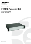
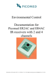
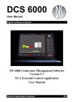
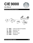
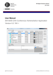
The front plate layout of the AO 6004 Audio Output Unit consists of 4 XLR Analog transformer balanced outputs and
2 DCS-LAN connectors:
Figure 0-A
AO 6004 Back Panel
4.1.3.2
Front plate controls and
indicators
The AO 6004 is an easy to use AO unit with preconfigured settings and no user interface in terms of
controls, display or indicators.
4.1.3.3
Front plate connectors
4.1.3.3.1 Audio Output A to D
On the front are located 4 XLR 3P connectors, each
supplying transformer balanced audio signal from
each of the 4 channels.
The outputs can be used for tape recording purpose
i.e. or for connecting a Digital infrared transmitter
like DT 6008, DT 6032 or an Analog infrared
transmitter for wireless transmission of the
interpreted languages.
4.1.3.3.2 DCS-LAN connector
Two RJ45 sockets are located at the front of the unit
for connecting to the previous unit like the CU
6105/CU6110 Central Unit or any other unit with a
DCS LAN connector and to the next unit like an IS
6132 Interpreter Unit, CS 6340 Channel Selector,
DM/CM 6xxx Conference Unit.
4.1.4
System settings
4.1.4.1
Pre-configured settings
The AO 6004 comes with pre-configured settings and
can be used without additional configurations.
The AO 6004 automatically assigns channels to the
outputs at start-up. Output A is assigned channel 0
(Floor), Output B is assigned channel 1, Output C is
assigned channel 2 and Output D is assigned channel
3.
8
The output volume for each channel is +3 dB, which is
the recommended level for connecting to DT 60xx.
The unit can be re-configured using SW 6000. The
settings for a reconfigured unit can be saved in the CU
6105/CU6110.
4.1.4.2
SW6000 settings
The SW6000 can be used for changing the assignment
of channels to outputs and for setting the volume.
Both the Conference Administration Application
(CAA) and the Conference User Application (CUA) can
be used to configure the AO units connected. They
both have settings for assigning channels to each of
the 4 outputs A-D. Each output can be set to one of
the 31 language channels or one of the three Floor
channels:
Floor: automatic gain controlled output
Floor 1: loudspeaker unregulated audio
Floor 2: loudspeaker regulated audio
An ambient microphone will only be active on the
Floor channel, not on Floor 1 or Floor 2
Values: {Floor 2, Floor 1, Floor, 1,…, 30, 31}
The volume of the outputs can also be set if the
default settings are not appropriate.
Values: {Off, -40, -39,…, 14, 15}
Refer to the CAA and CUA User Manuals for more
details.
USER MANUAL AO 6004 REV B.DOCX
DIS
User Manual
4.1.5
Normal operation
4.1.5.1
Powering up
Connect the AO unit(s) to the rest of the system via
the DCS-LAN connectors and connect the audio
outputs to the appropriate units (tape recorders,
infrared transmitters, etc.).
During the initialization the AO unit will
automatically assign channels to the outputs. The unit
is immediately ready to use after start-up unless
other channels need to be assigned to the outputs or
the channel volume needs to be adjusted. These
adjustments can only be done using the SW 6000.
Switch on the power on the Central Unit.
USER MANUAL AO 6004 REV B.DOCX
9
DIS
User Manual
5 System Setup
5.1
General guidelines
Connect the AO 6004 to the DCS-LAN using shielded
CAT5e cables (F/UTP or U/FTP)
Please observe the following guide lines:
•
5.2
Maximum cable length in one chain is 200 m
without
repeater.
This
includes
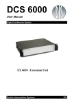
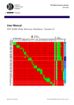
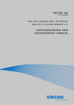
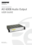
Typical schematics
Connect the AO 6004 to the DCS 6000 network using
Cat 5 cables. The Analog Audio output connectors are
connected to either tape recorders for recording the
Figure 0-A
10
•
interconnection cables between the units.
The max. usable cable length depends on the
units connected and length of feeding cables
etc.
Maximum cable length in one chain when
using repeaters is 650 m..
interpreted channels or to a DT 6008 Infrared
Transmitter for transmitting the interpreted channels
wireless.
Typical schematic
USER MANUAL AO 6004 REV B.DOCX
DIS
5.3
User Manual
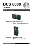
Using AO 6004 with DT 60xx Digital IR-Transmitter
When using the AO 6004 with the DT 60xx Infrared
Transmitter, the audio output level on the AO 6004
has to be set to match the sensitivity on the
transmitter.
The correct level on each connected channel on the
AO 6004 is +3dB. This level is factory preset, but can
as earlier mentioned be changed using SW 6000.
Please refer to the section ‘Pre-configured settings’ on
page 8. The DT 60XX input level settings should be set
to –6dB.
USER MANUAL AO 6004 REV B.DOCX
11
Danish Interpretation Systems
User Manual
6 Technical Specifications
6.1
Technical specifications
Digital Section
Storage temperature
Sound quality ..... 20 bit audio @ 32 kHz sampling frequency
............................. -20 Deg C. to 60 Deg C. (10 to 80 % humidity)
Analog Section
Output signal type ........... ground lifting transformer balanced
Nominal output level: ............................ 0 dBm at nominal input
Weight .............................................................................................0.84 kg
Dimensions (W x H x D).........180 (205) x 38 x 120 (120) mm
Dimensions in bracket are including brackets
Max. Output level: .....................................................................15 dBm
Connectors
Signal to noise ratio: ............................................................ >85 dBA
Analog outputs connectors ............. 4 - XLR3 male connectors
Frequency response ............................................................ 50-16kHz
DCS-LAN network ......................................................... 2 pieces RJ45
Total harmonic distortion: ................................................... < 0.1%
Remote Control commands in/out
General
Power requirement ...........................................................24-48 V DC
Power consumption .................................................... 2W maximum
Power supplied from ..................CU 61xx / EX 6010 / PS 6000
Temperature to guarantee specified performance
.................................. 5 Deg C. to 40 Deg C. (35 to 80 % humidity)
6.2
* .................................... Channel number for each output channel
* .......................................................Volume setting for each channel
* The settings can only be read or controlled from the SW
6000.
Specifications are subject to change without notice.
Connection Details
DCS-LAN Chain
Pin
The DCS 6000 system uses Cat5e, Cat6 or Cat7 F/UTP
or U/FTP cables with screened RJ45 connectors.
EIA 568-B wiring shall be used.
Important: The names of Cat5/6/7 cable type have
changed.
Old name
New name
FTP
F/UTP
STP
U/FTP
UTP
U/UTP
Important: Use only F/UTP or U/FTP (screened) cables
and screened RJ45 connectors and not U/UTP cable, which
are unscreened.
How to wire a Cat5e (EIA 568-B) cable to a RJ45 con.:
12
By using SW 6000 the user can control the following
settings in the AO 6004 through the CU 6105/CU6110.
Function
Connector #1
Connector #2
1
In-going +
ORG/WHT
ORG/WHT
2
In-going -
ORG
ORG
3
+48V
GRN/WHT
GRN/WHT
4
0V
BLU
BLU
5
0V
BLU/WHT
BLU/WHT
6
+48V
GRN
GRN
7
Outgoing -
BRN/WHT
BRN/WHT
8
Outgoing +
BRN
BRN
Important: If other color codes are used then the four pairs
are connected as follows:
Pair 2:
Pair 3:
Pair 1:
Pair 4:
USER MANUAL AO 6004 REV B.DOCX
Pin 1 & 2
Pin 3 & 6
Pin 4 & 5
Pin 7 & 8
Danish Interpretation Systems
User Manual
The phase of the pairs must be correct and the wiring
spec. as stated in Cat5e (EIA 568-B) have to be
followed.
Note: Cat6 and Cat7 cables can normally only be
terminated in sockets (female) and not in cable plugs.
Cat6 and Cat7 can thus only be used for feeding cables
terminating in wall outlets or patch panels.
6.3
Analog Audio Out
XLR3 male
Pin
Signal
Cable type
1
Earth
2 x 0.25 mm2 shielded.
2
Signal +
3
Signal –
Accessories
Cat5e Connection Cables (AWG24)
EC 6001-0.5 Connection Cable 0.5 m ..................... 10 03 22500
EC 6001-01 Connection Cable 1 m .......................... 10 03 23101
EC 6001-02 Connection Cable 2 m .......................... 10 03 23201
EC 6001-10 Connection Cable 10 m ....................... 10 03 24102
EC 6001-20 Connection Cable 20 m ....................... 10 03 24202
EC 6001-50 Connection Cable 50 m ....................... 10 03 24502
EC 6001-05 Connection Cable 5 m .......................... 10 03 23501
USER MANUAL AO 6004 REV B.DOCX
13