1
Address:
SINTEF group, MARINTEK,
Structural Engineering
Box 4125, Valentinlyst
7450 Trondheim
Norway
COMMENTS ARE INVITED
Release Notes
USFOS Version 7-7
www.sintef.no
FOR YOUR ATTENTION
MEMO CONCERNS
AS AGREED
FOR YOUR INFORMATION
MEMO
DISTRIBUTION
Members of USFOS user group
x
Location: Otto Nielsens vei 10
Tel
Fax
:+47 7359 5611
:+47 7359 2660
FILE CODE
CLASSIFICATION
Open
ELECTRONIC FILE CODE
PROJECT NO.
DATE
700030
2000-04-01
PERSON RESPONSIBLE/AUTHOR
Tore Holmås
NUMBER OF PAGES
31
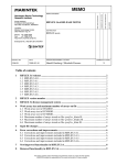
Release notes
USFOS 7-7, April 2000
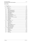
Contents:
1.
INTRODUCTION .......................................................................................................................................2
2.
CONTENTS OF CD-ROM.........................................................................................................................2
2.1.
2.2.
2.3.
2.4.
3.
EFFICIENT USE OF USFOS ....................................................................................................................5
3.1.
3.2.
3.3.
3.4.
3.5.
3.6.
3.7.
3.8.
4.
OVERVIEW .................................................................................................................................................2
NEW VERSIONS OF THE PROGRAM CODES...................................................................................................2
MANUAL....................................................................................................................................................4
EXAMPLES .................................................................................................................................................4
GENERAL ...................................................................................................................................................5
ADJUSTING THE UNIX KORN SHELL WINDOW ..............................................................................................6
SOME UNIX COMMANDS .............................................................................................................................9
EXAMPLE 1, FIXED USFOS INPUT FILE NAMES ..........................................................................................10
EXAMPLE 2, VARYING USFOS INPUT FILE NAMES .....................................................................................11
EXAMPLE 3, ASSEMBLING INPUT FILES BEFORE USFOS ANALYSIS ............................................................13
EXAMPLE 4, USING THE SED EDITOR TO MODIFY MASTER INPUT FILES ...................................................15
EXAMPLE 5, PROCEDURE FOR ELEMENT REMOVAL (REDUNDANCY ANALYSIS)........................................20
NEW FEATURES .....................................................................................................................................23
4.1. GROUP DEFINITION ..................................................................................................................................23
4.2. MODEL REPAIR ........................................................................................................................................24
4.3. JOINT CLASSIFICATION / MSL JOINT CHARACTERISTICS ...........................................................................28
5.
NEW/MODIFIED INPUT IDENTIFIERS..............................................................................................31
This memo contains project information and preliminary results as a basis for final report(s).
SINTEF accepts no responsibility of this memo and no part of it may be copied.
2
___________________________________________________________________________
1.
Introduction
The current version of USFOS (version 7-7, 2000-04-01) is the intermediate release of the 9900 user group development period.
The current release with date 2000-04-01 contains following:
CD-ROM
Updates of User’s Manual
Release Notes (this MEMO)
2.
2.1.
Contents of CD-ROM
Overview
The CD contains documentation, examples and new versions of the program codes, and the
organisation is described in Figure 2.1-1. Both UNIX and NT solutions are collected in the
same CD.
Figure 2.1-1 Contents of CD-ROM
2.2.
New versions of the program codes
Under each file folder (f ex “USFOS_for_Windows_NT4.0”), two folders, (bin and etc) are
located. The “bin” folder contains the program code, while the “etc” folder contains set up
files.
________________________________________________________________________________________________
Release Notes USFOS version 7-7
SINTEF 2000-04-01
3
___________________________________________________________________________
Figure 2.2-1 Program Code located in “bin” folder
Figure 2.2-2 Files in “etc” folder. NT (to the left) and UNIX (to the right)
Installation on UNIX:
Create a root directory for USFOS, (the new “USFOS_HOME ” directory)
Copy the actual “bin” and “etc” directories to USFOS_HOME
Copy the “Examples_UNIX” and “Document” directories to USFOS_HOME.
Define the USFOS_HOME variable in the USFOS.cshrc/USFOS.kshrc files
Figure 2.2-3 Contents of "$USFOS_HOME" folder after installation
________________________________________________________________________________________________
Release Notes USFOS version 7-7
SINTEF 2000-04-01
4
___________________________________________________________________________
Installation on Windows NT 4.0
Copy the new “.exe” files located in the “bin” folder to the existing “USFOS_HOME/bin”
folder
Copy the new “postfos.inca” file located in the “etc” folder to the existing
“USFOS_HOME/etc” folder
Copy the “Examples_PC” and “Document” folders to the existing USFOS_HOME.
NOTE ! : If USFOS has never been installed on NT before, please contact SINTEF.
For all systems:
Copy the file: “USFOS.key” (delivered on a separate diskette) to the actual
“USFOS_HOME/etc” directory.
2.3.
Manual
The User’s manual is updated, and (paper) copies of the actual pages are delivered. In
addition, the most important part of the manual, the “Input Description” (USFOS_UM_06) is
available for “on-line” reading using f ex. Adobe Acrobat Reader or any other "PDF readers".
A free "PDF-reader" is available on www.adobe.com .
2.4.
Examples
Approx. 50 examples are given under the “Examples” directories. The contents of the UNIX
and PC examples are identical, (the only reason for having two folders is due to computer
compatibility, UNIX and PC represent the files differently).
The input files are located in separate folders, one example per folder, see Figure 2.4-1. In
each folder, following files are found:
Head.fem : USFOS control parameters
________________________________________________________________________________________________
Release Notes USFOS version 7-7
SINTEF 2000-04-01
5
___________________________________________________________________________
Stru.fem :
Structure and load description in either SESAM or UFO file format. In some
cases both SESAM and UFO formats are given for the same example, and then
the “stru-file” has a postfix, u for UFO and s for SESAM. Any of the two variants
(stru_u.fem or stru_s.fem) should produce the same results. The USFOS control
parameters are unaffected by the file format used to describe the structure and
loads. (See also Chapter 3).
Figure 2.4-1 Example folders available for UNIX and NT( PC)
Figure 2.4-2 Contents of “Script folder available for UNIX and NT( PC)
3.
3.1.
Efficient use of USFOS
General
Seldom, only one USFOS analysis is performed for a given problem. The more typical use is
repeated runs due to several load cases, parametric (sensibility) study, model change, etc.
In cases where many USFOS analyses should be performed, well organising of both input and
output files is important. There should be no doubt about “what was the parameters used for
________________________________________________________________________________________________
Release Notes USFOS version 7-7
SINTEF 2000-04-01
6
___________________________________________________________________________
this particular result plot” and so on. It is highly recommended to not use one input file set,
which is modified over and over again until all cases are run, because:
Possible confusion about input parameters used
Difficult to repeat the analyses after a time
Requires manual editing before each new run, impossible to automate
It’s better to plan and organise the USFOS analysis in a way that makes it possible to,
ultimately, perform hundreds of analyses using only one, (magic) command. One solution
(among several) is using UNIX scripts, and the following sections will describe this solution.
USFOS (even on Windows NT ) runs in a UNIX environment, and all procedures described in
the sections below are running on “all” computer platforms. However, some differences may
occur, (f. ex: C:/TEMP on PC and /tmp on standard UNIX).
The next sections will deal with use of UNIX commands typed in from the keyboard in the
“old fashion way”. It’s therefor worth spending some minutes adjusting the UNIX command
prompt window.
3.2.
Adjusting the UNIX korn shell window
Before you start using the UNIX korn shell, it’s recommended to modify slightly the layout.
Figure 3.2-1 shows the default window with white text an black background and with size 24
lines / 80 columns). To modify the window, point on the (blue) top frame of the window, and
press the right hand button. The menu Figure 3.2-2 appears.
Figure 3.2-1 The default NutCracker Window layout
Figure 3.2-2 Menu
________________________________________________________________________________________________
Release Notes USFOS version 7-7
SINTEF 2000-04-01
7
___________________________________________________________________________
Select Properties and the “select colors” menu shown in Figure 3.2-3 appears.
Select screen text and screen background among the indicated colours. The light grey
background together with black text is a good combination.
Figure 3.2-3 Defining screen- and text colour
The default window has no screen buffer (has no scroll bar), but the buffer sizes in vertical
(number of lines) and horizontal (number of columns) are possible to specify under the layout
menu, see Figure 3.2-4. Type in (or us the arrow) the actual sizes, which here is set to
132/2048. The window size when it pops up is set to 80/40.
When the OK button is pressed, the menu shown in Figure 3.2-5 appears. Select “Modify
Shortcut” to save the settings permanently.
Figure 3.2-4 Defining window layout
________________________________________________________________________________________________
Release Notes USFOS version 7-7
SINTEF 2000-04-01
8
___________________________________________________________________________
Figure 3.2-5 Selecting permanent modification of the short cut
The UNIX window will from now on look like the one in Figure 3.2-6 with two scroll bars
(and it’s resizable) and a comfortable colour.
Figure 3.2-6 The modified NutC window with scroll bar.
________________________________________________________________________________________________
Release Notes USFOS version 7-7
SINTEF 2000-04-01
9
___________________________________________________________________________
3.3.
Some UNIX commands
The procedures described in the examples below require that the users knows some UNIX
commands, and in the following a brief summary of the commands used in the scripts is
given:
Command /
Argument
Description
Use
cp
mv
cat
cat >
cat >>
Copy one file into another
Rename a file or directory
dump the content of a file to screen
dump the content of file_1 into file_2
dump content of file1 behind existing content of
file 2 (append)
create a directory (folder)
change directory
directory path. (one level up)
directory path. (two levels up)
directory path (one level up and one down)
cp “from file” “to file”
mv “from name” “to name”
cat “file”
cat “file1” > “file2”
cat “file1” >> “file2”
mkdir
cd
..
.. /..
.. /dir_name
$NAME
echo $NAME
sed
rm
Environmental variable with name NAME
“Show me the content of the environmental
variable whit name NAME”
“Stream Editor”
Delete file(s)
rmdir
ls
ls *.fem
Delete directory
List files
List all files with extension .fem
mkdir “directory name”
cd “directory name”
cd ..
cd .. /..
cd
.. /case2
cp “file1”
“.. /case2/file2”
cp $MASTER/file1 file2
Will be used in the examples below
Will be used in the examples below
rm file1
rm file1 file2 file3 ….
rmdir directory_name
ls
Table 3.3-1 UNIX commands overview
________________________________________________________________________________________________
Release Notes USFOS version 7-7
SINTEF 2000-04-01
10
___________________________________________________________________________
3.4.
Example 1, Fixed USFOS input file names
The simplest example on a UNIX script (which saves you for tediously typing) is a file with
name go1 containing following:
$USFOS_HOME/bin/usfos
head
stru
load
res
ENDIN
15
<< ENDIN
Table 3.4-1 Content of script file: "go1" with 3 fixed USFOS input files
Explanation:
The variable USFOS_HOME is set during installation of USFOS on both UNIX and NT computers.
It contains the file path of the root of the actual USFOS version. By prefixing the variable name
with $, the contents of the variable name becomes available for use in connection with any
UNIX command.
“$USFOS_HOME/bin/usfos” is the address to the USFOS code, and by adding 15 after the file
name, a workspace of 15 mill is required.
The “<< ENDIN” defines that the usual screen input/output is given between in the lines
between << ENDIN
and
ENDIN
The name “ENDIN” is an arbitrarily chosen name of the label.
In a usual USFOS run, it’s first asked for the control file name prefix, which here is set to
“head”. Further it’s asked for the structural and load files, which here are “stru” and “load”
respectively.
Finally, USFOS asks for the result file prefix, which is set to “res”.
By typing go1 USFOS will start, use the input files head.fem, stru.fem and load.fem, and store
the results in files with prefix: res. All input files must be located on the same directory as the
script file go1 , and results are stored in the same directory.
As USFOS accepts input from one, two or 3 files, it’s possible to leave up to two file names
blank as shown in Table 3.4-2, where the ‘load’ file is left out.
$USFOS_HOME/bin/usfos
head
stru
15
<< ENDIN
res
ENDIN
Table 3.4-2 Content of script file: "go2" with only “head” and “stru” input files
________________________________________________________________________________________________
Release Notes USFOS version 7-7
SINTEF 2000-04-01
11
___________________________________________________________________________
It is possible to access files located on other directories than the directory where the script go
is located /and started from). Table 3.4-3 describes the case where some files are located on
different directories:
$USFOS_HOME/bin/usfos 15
<< ENDIN
head_intact_nw_100yr
../model/intact_stru
../loads/nw_100yr
D:/temp/res_intact_nw_100yr
ENDIN
Table 3.4-3 Content of script file: "go3" with input files located on different directories
In this case, the control file (head_intact_nw_100yr.fem) is located on same directory as the
script file (and where the script is started from). The structural file (stru.fem) is located in the
directory model (which is located on same level, besides, the current directory), and the file is
named intact_stru.fem.
The load file is located on an other directory (also on same level as the other two) with name
loads, in a file with name nw_100yr.fem
The results are saved on the D: disc, on a directory named temp, and file res_nw_100.raf.
The third variant of the “fixed name script”: go3 indicates a first try to organise an analysis
series involving several versions of the structural file, (f ex intact and damaged), and several
loads (f ex nw_100yr, nw_1000yr, sw_100yr, sw_1000yr, etc).
This leads to the next example, which will give an example on how a slight modified go3
could be used for many different analyses.
3.5.
Example 2, Varying USFOS input file names
The “fixed name script”, go3 described above is slight modified. Instead of defining the file
names 100%, some of the file name is substituted by the keywords $1 and $2. It’s possible to
give input parameters to UNIX scrips, and $1 is parameter no. 1, $2 is parameter no. 2 etc…
$USFOS_HOME/bin/usfos
head_$1_$2
../model/$1_stru
../loads/$2
D:/temp/res_$1_$2
ENDIN
15
<< ENDIN
Table 3.5-1 Content of script file: "go" with varying input file names
By typing:
go intact nw_100yr
the same analysis as described under example 1, go3 will be performed.
________________________________________________________________________________________________
Release Notes USFOS version 7-7
SINTEF 2000-04-01
12
___________________________________________________________________________
The $1 variable will be expanded to intact inside the script, and $2 will be expanded to
nw_100yr, which gives the actual file names:
Control file
Struct file
Load file
Result file
:
:
:
:
head_intact_nw_100yr
../model/intact_stru
../loads/nw_100_yr
D:/temp/res_intact_nw_100yr
$1
$2
A script file may not only refer to UNIX commands, it’s possible to refer to other script files as
well. This leads to next level in script programming: defining a top level script, which refers
to user defined script(s).
If f ex. one analysis series should consist of a number of different structural conditions,
different load directions and – conditions, the following script named run_all would run
through all 16 cases without need for any human interference.
# ----------------------------------------------------# -- Script for running: - 2 structural conditions, -# -- 4 load directions and
-# -- 2 load conditions
-# -- Totally 2x4x2=16 cases.
-# ----------------------------------------------------#
#
Structure
Load
go
intact
nw_100
go
intact
sw_100
go
intact
se_100
go
intact
ne_100
#
go
intact
nw_10000
go
intact
sw_10000
go
intact
se_10000
go
intact
ne_10000
#
go
damaged
nw_100
go
damaged
sw_100
go
damaged
se_100
go
damaged
ne_100
#
go
damaged
nw_10000
go
damaged
sw_10000
go
damaged
se_10000
go
damaged
ne_10000
# ---------------- End of S ript File ------------------
Table 3.5-2 Content of level 2 script file: "run_all", which refers to “go”.
________________________________________________________________________________________________
Release Notes USFOS version 7-7
SINTEF 2000-04-01
13
___________________________________________________________________________
3.6.
Example 3, Assembling input files before USFOS analysis
In the previous examples, all input files were complete before the script was executed. In may
cases, only a small fraction of the entire input is different from one case to another. Instead of
making lots of copies of near 100% equal files, the key in this example is to show how the
input files could be composed by common information + some special information.
Common information:
Control file,
:
Main structure located in :
Main load located in
:
head.fem
str/Main_Strucutre
loa/Main_Load
Special information:
Support Structure
Special Load
:
:
str/Spring_Support_1 and _2
loa/Nodei_Load
Figure 3.6-1 Content of file folder before running script "run_all".
The idea is as follows:
Use the control file head.fem in all cases.
Compose a structural file consisting of the common Main_Structure and the special
support, and assemble the complete structural model in the file stru.fem.
Compose a load file, which should consist of the common load file Main_Load and the
special nodal load, and collect all load info in the file load.fem.
Create a new, unique directory (below current directory) for each case with informative
name reflecting the actual case.
Run USFOS an save stru- and load files + result files on the actual directory.
Create script go for running on case, and run_all for running all 6 combinations
In Table 3.6-1 the script with name go is described in detail as it appears in the example
folder. Lines staring with the sign # is comment lines, and may appear anywhere in the script
file except between << ENDIN and ENDIN. (It is recommended to use comments, both in
scripts and in the USFOS input files).
Firstly, the cp command is used to copy the main structure to the file stru.fem. Next, the
selected support structure is appended to the stru.fem using the cat >> command. Similar is
done for the load file assembly.
________________________________________________________________________________________________
Release Notes USFOS version 7-7
SINTEF 2000-04-01
14
___________________________________________________________________________
A unique directory for each case is created using the mkdir command, and the directory name
(with prefix Case_) contains information about both support and load. USFOS is started with
15 mill and results are saved in the actual Case directory using the result file prefix res for all
cases (the directory contains information about the different cases). Finally, the actual
stru.fem and load.fem are moved into the actual Case directory using the mv command. (Note
that if only directory name is defined in connection with the mv command, the file name will
be unchanged in the new directory, just moved.)
# =======================================================
# -- Script for assembling USFOS input and run USFOS
-# -- Usage: go
par1
par2
-# -- par1 : Support Structure
-# -- par2 : Load definition
-#-------------------------------------------------------#
- Copy Main Structure into
#
file stru.fem and add
#
selected support:
cp
str/Main_Structure
stru.fem
cat str/$1
>> stru.fem
#
- Copy Main Load into
#
file load.fem and add
#
selected load:
cp
loa/Main_Load
load.fem
cat loa/$2
>> load.fem
#
- Run USFOS and save results
#
in unique directories:
#
#
.. Create Directory
mkdir Case_$1_$2
$USFOS_HOME/bin/usfos 15
<< ENDIN
head
stru
load
Case_$1_$2/res
ENDIN
#
.. Move stru.fem and load.fem
#
into actual Case_Dir for
#
backup purpose.
mv stru.fem
Case_$1_$2
mv load.fem
Case_$1_$2
#
# ---------------- EOF -------------------------------
Table 3.6-1 Content of script file: "go" which assembles input files & runs USFOS
#
go
go
go
#
go
go
go
#
Support
Spring_Support_1
Spring_Support_1
Spring_Support_1
Loa
Node1_Load
Node3_Load
Node5_Load
Spring_Support_2
Spring_Support_2
Spring_Support_2
Node1_Load
Node3_Load
Node5_Load
Table 3.6-2 Content of script file: "run_all", which executes the script “go”.
After the script run_all is completed, 6 new file folders (directories) are created, see Figure
3.6-2. All directories contain the actual, assembled input (stru and load) + the result files
(res.*).
________________________________________________________________________________________________
Release Notes USFOS version 7-7
SINTEF 2000-04-01
15
___________________________________________________________________________
Figure 3.6-2 Content of file folder after running script "run_all".
3.7.
Example 4, Using the SED editor to modify master input files
In the previous example, the input to USFOS was composed by some common files + special
files, and in all cases the content of the files were pre defined.
In the current example, another, and even more flexible solution is chosen. Instead of
assembling ‘pieces’ of input, the content of the input file(s) are modified prior to the analysis.
As the modification should be performed in a batch run, a batch editor is necessary. The UNIX
shell on both UNIX workstations and the “NutCracker” UNIX shell on Win-NT offers the SED
editor, the “Stream EDitor”.
The operation needed from the stream editor is the “REPLACE” or “SUBSTITUTE”
command, where one character string should be replaced by another.
The (cryptic) UNIX command is wrapped into a file, which here is named substitute, Table
3.7-1, and which is used as follows:
Substitute
“string_1”
“string_2”
FileName
In all connections where string_1 occur on the specified file, it’s replaced by string_2. The
SED editor is case sensitive (differs between upper and lower case characters). Quotes must be
used if blank character(s) occur in the strings.
sed "1,$ s/$1/$2/g" $3 > subst_string.temp
mv subst_string.temp $3
Table 3.7-1 Script “substitute”, which utilises the SED editor for substituting strings.
________________________________________________________________________________________________
Release Notes USFOS version 7-7
SINTEF 2000-04-01
16
___________________________________________________________________________
With the powerful substitute script available, following operations should be done:
Create only one master USFOS control file (which should be used for all cases)
Use one structural file
Run USFOS wave analysis for 8 different wave/current conditions.
As indicated in Figure 3.7-1, some files are present before the analyses are performed, and
some are created during the analysis (executing the scripts defined in this section).
These files/folders are
present before running
the scripts
These files/folders are
present after running
”run_all”
Figure 3.7-1 Files / Folders before and after running the scripts
Master Headfile, Table 3.7-2.
The file is an ordinary control file for USFOS, but some parameters are not yet set. Instead, the
parameters are represented by arbitrarily chosen key words. In the actual study, the wave
height, direction and period should be varied, and the keyword for the wave height is WAVEH,
the keyword for direction is DIRECT, and the keyword for wave period is PERIOD.
Script file “go”,Table 3.7-3 :
The first operation in the script is creating a directory using the mkdir command, and all 3
parameters (wave- height, direction and period) are included in the directory name.
Next, the nearly complete USFOS control file (named Master_Headfile and located in directory
model) is copied into the file head.fem on current directory. The script for substituting
(named substitute) is used three times for replacing the keywords with the actual parameter
values.
Then USFOS is run, and the same structural file (stru.fem) is used for all cases. Results are
saved on the actual Case directory, and result prefix is res. When USFOS is finished, the
(manipulated) head.fem is moved into the actual Case directory, (see Table 3.7-5 for example
on modified head file).
________________________________________________________________________________________________
Release Notes USFOS version 7-7
SINTEF 2000-04-01
17
___________________________________________________________________________
HEAD
USFOS Extreme Wave. Height: WAVEH , Dir: DIRECT , T : PERIOD
Progressive Collapse Analysis / JACKET model
SINTEF 2000
'
'
'
'
'
WAVEDATA
'
'
CURRENT
- Define Wave:
Ildcs
2
<type>
H
Stoke WAVEH
Period
PERIOD
Direction Phase
DIRECT
0.0
Ildcs
2
Speed Direction Surf_Lev Depth
2
DIRECT
0.0
100
Surf_Lev Depth
0.0
100
[Profile]
0.0 1.0
-20.0 1.0
-100.0 0.0
Table 3.7-2 “Master_Headfile” with keywords: WAVEH, DIRECT and PERIOD
# =======================================================
# -- Script for assembling USFOS input and run USFOS
-# -- Usage: go
Wave_Height
Direction
Period
-#-------------------------------------------------------#
.. Create Directory
mkdir Case_H=$1_Dir=$2_T=$3
#
#
- Copy Master control file
#
into the current head
#
file:
cp
model/Master_Headfile
head.fem
#
.. Substitute the string
#
"WAVEH" with the first
#
script parameter ($1)
#
substitute
WAVEH
$1
head.fem
#
.. Similar for par. 2 & 3:
substitute
DIRECT
$2
head.fem
substitute
PERIOD
$3
head.fem
#
- Run USFOS and save results
#
in unique directories:
#
$USFOS_HOME/bin/usfos 15
<< ENDIN
head
model/stru
Case_H=$1_Dir=$2_T=$3/res
ENDIN
#
#
#
mv head.fem
Case_H=$1_Dir=$2_T=$3
#
.. Move head.fem
into actual Case_Dir for
backup purpose.
Table 3.7-3 Script file “go”
________________________________________________________________________________________________
Release Notes USFOS version 7-7
SINTEF 2000-04-01
18
___________________________________________________________________________
Script file “run_all” Table 3.7-4
The script file run_all starts go 8 times with different input parameters.
# =======================================================
# -- Script for running 8 diffenent USFOS cases
-#-------------------------------------------------------#
#
#
Wave Height
Wave/Curr Direction
Period
go
20.0
00.0
16.0
go
20.0
30.0
16.0
go
20.0
60.0
16.0
go
20.0
90.0
16.0
#
go
24.0
00.0
20.0
go
24.0
30.0
20.0
go
24.0
60.0
20.0
go
24.0
90.0
20.0
#
# -------------- End of Script run_all ----------------
Table 3.7-4 Script file “run_all”
HEAD
USFOS Extreme Wave. Height: 20.0 , Dir: 00.0 , T : 16.0
Progressive Collapse Analysis / JACKET model
SINTEF 2000
'
'
'
'
'
WAVEDATA
'
'
CURRENT
Table 3.7-5
- Define Wave:
Ildcs
2
<type>
H
Stoke 20.0
Ildcs
2
Speed Direction Surf_Lev Depth
2
00.0
0.0
100
USFOS
Period
Direction Phase Surf_Lev Depth
16.0
00.0
0.0
0.0
100
[Profile]
0.0 1.0
-20.0 1.0
-100.0 0.0
-110.0 0.0
control file modified by the SED editor.
After all 8 cases are run, 8 new directories are created (see Figure 3.7-1) containing the
modified head.fem and the analysis results. Figure 3.7-2 shows results from one of the 8
analyses, and NOTE that the member imperfections (command CINIDEF) are applied
automatically according to the actual wave load direction (which here is 30°).
________________________________________________________________________________________________
Release Notes USFOS version 7-7
SINTEF 2000-04-01
19
___________________________________________________________________________
Figure 3.7-2 Case with H=20m, Dir=30deg and T=16s
________________________________________________________________________________________________
Release Notes USFOS version 7-7
SINTEF 2000-04-01
20
___________________________________________________________________________
3.8.
Example 5, Procedure for element removal (redundancy analysis)
The final example solves following problem:
Remove the structural members, one by one
Use the same structural file and control file
Save the results from the analyses in separate file folders
Figure 3.8-1 shows the content of the example folder before and after running the actual
scripts. The scripts are organised in the etc folder, while the structural model is stored in the
model folder. The content of the script files are described in Table 3.8-1, Table 3.8-2 and
Table 3.8-4.
Figure 3.8-1 Files / Folders before and after running the script
#
- Define varible SCRATCH
#
(directory for Raf file storing)
export SCRATCH=/tmp/scratch
#
#
Local Dir
Element to remove
elmdel
Elem_01
01
elmdel
Elem_02
02
elmdel
Elem_03
03
elmdel
Elem_04
04
elmdel
Elem_05
05
elmdel
Elem_06
06
elmdel
Elem_07
07
elmdel
Elem_08
08
elmdel
Elem_09
09
elmdel
Elem_10
10
elmdel
Elem_11
11
elmdel
Elem_12_and_13
12 13
elmdel
Elem_05_06_and_12
5
6 12
#
# ------------- End of Run_All -------------------
Table 3.8-1 Script file “run_all”
________________________________________________________________________________________________
Release Notes USFOS version 7-7
SINTEF 2000-04-01
21
___________________________________________________________________________
The run_postfos script runs POSTFOS and creates the default history table, using the definehistory and print-history commands. (Similar scripts could be created for extracting nodal
displacements of selected nodes, element forces etc.)
$USFOS_HOME/bin/usfos
head
stru
load
$SCRATCH/res
ENDIN
<< ENDIN
$USFOS_HOME/bin/postfos
<< ENDIN
$1
define-hist,,,,,,
print-hist,,,,,,,
q
ENDIN
Table 3.8-2 Scrips: “run_usfos”
and
“run_postfos”
Figure 3.8-2 shows the content of one automatically created file folder (named Elem_01),
which contains the global history created by POSTFOS , the log files from the analysis and the
different input and output files. Table 3.8-3 shows the content of the file nonstru_elem.fem,
(which is created by the script), for two cases: To the left the case where element number 1
should become non structural, and to the right the case where elements 5,6 and 12 should be
removed.
Figure 3.8-2 Files created automatically in folder Elem_01
'
' ----------------------------' -- Nonstructural Members
-' ----------------------------'
'
Type
NONSTRU
Element
01
'
' --------- E O F -------------
'
' ----------------------------' -- Nonstructural Members
-' ----------------------------'
'
Type
NONSTRU
Element
5
NONSTRU
Element
6
NONSTRU
Element
12
'
Table 3.8-3 Automatically created files containing the NONSTRU comand.
________________________________________________________________________________________________
Release Notes USFOS version 7-7
SINTEF 2000-04-01
22
___________________________________________________________________________
########################################################################
#
Author : Tore Holmas, SINTEF Group. Norway
#
#
Date
: 2000-03-18
#
########################################################################
#
if
test "$#" -lt "2"
then
echo '
**************************************************'
echo '
*
*'
echo '
*
Creates the directory "../Label" ,
*'
echo '
*
creates a copy of usfos control file and
*'
echo '
*
adds necessary NONSTRU commands.
*'
echo '
*
*'
echo '
*
Assumes structural file on ../model/stru.fem *'
echo '
*
*'
echo '
*
Results are stored on file "$SCRATCH/res"
*'
echo '
*
*'
echo '
*
Usage: elmdel <Label> elem1 elem2 elem3 .. *'
echo '
*
*'
echo '
*
2re, March 2000 *'
echo '
**************************************************'
else
echo " "
echo " Creates directory ../$1
"
mkdir
../$1
cd
../$1
count="1"
for i do
if (test "$count" -gt "1")
then
echo "
Processing Element
: $i "
if (test "$count" -eq "2")
then
#
- Heading :
echo "'
"
> nonstru_elem.fem
echo "' ----------------------------- "
>> nonstru_elem.fem
echo "' -- Nonstructural Members
-- "
>> nonstru_elem.fem
echo "' ----------------------------- "
>> nonstru_elem.fem
echo "'
"
>> nonstru_elem.fem
echo "'
Type
"
>> nonstru_elem.fem
fi
#
- Add to file :
echo " NONSTRU
Element
$i "
>> nonstru_elem.fem
if (test "$count" -eq "$#")
then
#
- Tail:
echo "'
"
>> nonstru_elem.fem
echo "' --------- E O F ------------- "
>> nonstru_elem.fem
fi
fi
#
- Update counter:
count=`expr $count + 1`
done
# =================================================================
echo " Grabbing USFOS master control file from ../model "
cp ../model/head.fem
.
echo " Adds nonstru commands ...........
"
cat nonstru_elem.fem >> head.fem
echo " Creates Case identifier : $1 on head.fem
"
../etc/substitute CASEID
$1
head.fem
echo " Grabbing USFOS stru & load file from
../model "
cp ../model/stru.fem
.
cp ../model/load.fem
.
echo " and start USFOS
"
../etc/run_usfos
>
run.log
echo " and POSTFOS
"
../etc/run_postfos $SCRATCH/res >>
run.log
echo "
"
echo " Saves Global History on current directory ....... "
echo "
"
echo "
"
echo "
"
echo "
"
mv $SCRATCH/res.pri
Global_History
mv $SCRATCH/res_status.text
.
fi
Table 3.8-4 Script file “elmdel”
________________________________________________________________________________________________
Release Notes USFOS version 7-7
SINTEF 2000-04-01
23
___________________________________________________________________________
4.
New Features
4.1.
Group definition
Groups are introduced in the latest USFOS version (7-7).
A group is identified by its ID, which is a number (up to 8 digits).
Elements become “members of” groups, and the same element may participate in several
groups.
The nodal points, to which the elements are attached, becomes “members of” the actual
group.
The groups are referred to in connection with assigning properties to elements, which will
ease the input (reduce the amount of input lines). In xfos its possible to include/exclude
groups in the structural image (Edit/Clip/Group).
Elements are defined “members of” a group using the GROUPDEF command. The element may
be identified through:
Element ID
All elements referring to given material ID’s
All elements referring go given cross section geometry ID’s
All elements ‘members of’ existing groups
The actual way of defining the elements is specified using the parameters “Elem”, “Mat”,
“Geo” or “Group” as shown in Table 4.1-1.
'
GroupDef
GroupDef
GroupDef
GroupDef
'
ID
888
88881
88
8
Type
Elem
Mat
Geo
Group
{ ID-List }
10 20 30
1
5
88881 88
Table 4.1-1 Defining element groups using of the GROUPDEF command
If wanted, extra nodes could be defined “members of” an actual group, and the command
“groupnod” is used for this purpose, see Table 4.1-2. This command is used in connection
with ‘guiding’ loads from non structural members towards (kept) structural nodes.
'
GroupNod
Group ID
888
Nodes………
70 80 90
Table 4.1-2 Assigning (extra) nodes to a group using the GROUPNOD command
________________________________________________________________________________________________
Release Notes USFOS version 7-7
SINTEF 2000-04-01
24
___________________________________________________________________________
4.2.
Model repair
Creating an accurate structural model is
time consuming and costly, and it is
therefor normal to use existing models
rather than create new.
Existing models, in most cases, are created
for linear (design) analysis.
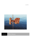
Figure 4.2-1 Large Challange for Non Linear Analysis
Seldom, existing models are created with non linear analysis in mind, and substantial work
has to be done before it’s suited for non linear problems. As computers are getting faster, the
model size may increase correspondingly. But, modification of models means in practice
manual work, and the bigger models, the more man hours have to be spent in order to ‘repair’
the linear model. A few years ago, a typical jacket structural model consisted of 500-1000
members. Today the same structure is represented by 5000-10000 members.
An increasing part of the model is non structural members introduced of different reasons in
the linear analysis, see Figure 4.2-1 for typical example.
If possible, the original structural model should become “read only”, and an “intelligent filter”
should transfer the ‘linear’ model into a model accepted by the non linear tool, see Figure
4.2-2.
Original “Linear” Model
(read only)
“Intelligent” filter
Shrinked, “correct”
model accepted by
the non linear tool
Figure 4.2-2 Preferred “Model Repair” solution
Often, the original (linear) model will not run at all, the analysis fails due to lack of boundary
conditions, etc. To be able to inspect the structure in XFOS, the use of the dynamic load
procedure is a useful intermediate solution, see Table 4.2-1. In an early modelling stage, the
gravity loading is sufficient load to ensure that all elements are connected, boundary
conditions correct, etc.
________________________________________________________________________________________________
Release Notes USFOS version 7-7
SINTEF 2000-04-01
25
___________________________________________________________________________
Dynamic
LoadHist
TimeHist
0.1
1
1
0.025
1
Points
0.1 0.1
0 0
1 1
1000 1
Table 4.2-1 Using dynamic load procedure
Table 4.2-2 shows the group definition used on a ‘real’ example, and it’s here defined 5
groups, which all use geometry ID’s to identify the elements. The general cross sections and
the small diameter pipes (D<300mm) are grouped, because elements referring to those beams
are the typical secondary members, which should be removed from the analysis model.
When the groups are defined, one single NONSTRU command will remove all the “members
of” the actual groups from the analysis model (but loads are kept).
'----------------------------------------------------------------' Specify Groups. (Which should become nonstructural)
'----------------------------------------------------------------'
Type
List......
GroupDef 1000 Geom
'
- GenBeams
'
10101 10228 10229 10230 10231 10251 10252 10352 15198 15199
16106 16129 16193 16194 16195 16196 16197 16198 16199 16206
16229 16293 16294 16295 16296 16297 16298 16299 16306 16329
16393 16394 16395 16396 16397 16398 16399 16406 16429 16493
16494 16495 16496 16497 16498 16499 16506 16529 16593 16594
16595 16596 16597 16598 16599 16606 16629 16693 16694 16695
16696 16697 16698 16699 17529 17592 17593 17594 17597 17598
17606 17629 17693 17694 17695 17696 17697 17698 17535 17600
17634
'
GroupDef 2000
Geo
'
- Pipes 1
'
19107 19108 16202 16302 10253 16102 16402 17502 17602 16502 16602
10102 10104 15110 19106 15186 10106 10105 10107 19105 15111 15106 19104 20110
10113 10360 10111 15185 15112 15107 10109 10112 19103 20095 20096 20094 15114
15113 20097 15191 20099 20098 16607 10117 16407 16307 16207 16107 16507 10365
10243 17607 10367 10118 10114 10116 10119 20111 10122 20124 16213 16212 16214
16109 16110 16209 16114 16210 16112 16113 17509 17510 17511 16614 16610 16612
16613 17512 17612 17613 17614 17610 17513 17514 17609 16609 16314 16409 16410
16313 16309 16310 16312 16412 16512 16513 16514 16510 16413 16414 16509 10121
10120 19102 16617 16616 15189 17517 17516 15115 16516 16416 16417 16316 16317
16517 15108 16216 10123 10125 10126 16217 17617 17616 16117 16116
16218 16119 16318 16118 16618 20085 16619 17619 17618 16519 20122 16419 16418
20112 16518 17620 16120 16420 16320 16520 16620 16220 10127 19101
'
GroupDef 3000
Geo
'
- Pipes 2
'
10102 10104 10105 10106 10107 10109 10111 10112 10113
10128 10130 10131 20072 20113 20114 10181 19109
20075 20076 20077 20073 20074 20080 20082 20080
20082 10185 10186 10102 10253 16202 16302 16402 16502 16602
17502 17602 10114 10365 10183
'
GroupDef 16319
Geo
16319
GroupDef 16219
Geo
16219
'
'-----------------------------------------------------------------------------' SPECIFY Groups 1000, 2000 and 3000 NonStructural.
'-----------------------------------------------------------------------------# NonStru Group
1000 2000 3000
Table 4.2-2 Shrinking model using the GROUPDEF and NONSTRU commands
If the definition of the bounding surface (the gbound command) is left out for general
sections, default values are used and a warning is printed, see Table 3.5-2. The default values
are shown in the same table.
________________________________________________________________________________________________
Release Notes USFOS version 7-7
SINTEF 2000-04-01
26
___________________________________________________________________________
*
*
*
*
Warning.
Warning.
Warning.
Warning.
GBOUND
GBOUND
GBOUND
GBOUND
input
input
input
input
not
not
not
not
specified
specified
specified
specified
for
for
for
for
General
General
General
General
GBOUND
Beam:
Beam:
Beam:
Beam:
10101
10101.
10228.
10229.
10230.
Default
Default
Default
Default
0.8
1.0
used.
used.
used.
used.
0.6
1.0
Table 4.2-3 Default “Gbound” data assigned to general beams
When element groups are defined, the contents of the different groups are listed in the .out
file, see Table 4.2-4. In the actual example, group no. 1000 is defined through geometry ID’s,
and the specified ID’s are listed first (similar if the group was defined through material ID’s).
Next, the elements, which are “members of” group no 1000 are listed, and finally, all nodal
point, to which the element are connected to are listed.
-----
G R O U P
D E F I N I T I O N S
-----
G R O U P
label
: "Geometry Group no
Contains following Geometries:
10101
10228
10229
10252
10352
15198
1000"
10230
15199
10231
16106
10251
16129
17535
17600
17634
............. :
5001
5007
5013
5019
5025
5031
5002
5008
5014
5020
5026
5032
5003
5009
5015
5021
5027
5033
5004
5010
5016
5022
5028
5034
5005
5011
5017
5023
5029
5035
5006
5012
5018
5024
5030
5036
78614
726500
78615
726501
755507
755508
726550
726551
......and nodes ............. :
54531
54837
54942
54943
54859
54834
54938
54939
54550
54961
54935
54936
54542
54856
54958
54930
54538
54543
54957
54561
54535
54539
54844
54557
54562
54536
54841
54950
54558
54863
......elements
Table 4.2-4 Print of group data: geometries, elements and nodes on the .out file.
The example shown in Figure 4.2-3, represents a first stage in a model repair procedure. The
entire structure is still “structural”, but members are grouped as specified above. By using the
Edit/Clip/Group command in xfos, it’s possible to visualise the different groups
(include/exclude). The image to the right shows the full model, and by excluding all groups as
seen in the “Specify Clip Group” menu, the image to the right appears.
If the NONSTRU command in Table 4.2-2 is activated (note that the # passives the command)
only the elements in the image to the right remains structural, but loads are attracted on the
full structure (image to the left).
________________________________________________________________________________________________
Release Notes USFOS version 7-7
SINTEF 2000-04-01
27
___________________________________________________________________________
Figure 4.2-3 Edit / Clip / Group
Useful USFOS commands for the “model repair” work:
GROUPDEF
GROUPNOD
NONSTRU
STRUCTEL
LIN_ELEM
:
:
:
:
:
Define element groups
Add nodes to groups (guide loads towards nodes)
Define elements nonstructural
Define elements structural (override NONSTRU for some elem.)
Define element linear elastic (with and without elastic buckling)
________________________________________________________________________________________________
Release Notes USFOS version 7-7
SINTEF 2000-04-01
28
___________________________________________________________________________
4.3.
Joint classification / MSL joint characteristics
This write-up is a preliminary description of the implementation of MSL joint formulation in
USFOS, for use with the β-release of the new feature.
The MSL equations are implemented with ductility limits and “post-rupture” unloading for
tension loading, but with no ductility limits for compression loading.
Joint failure in tension invokes the “FRACTURE” option in USFOS.
Joint utilisation will be visualised by colour fringes in Xfos
The following shows the input required to include MSL joint characteristics in the analysis of
a 2D K-frame. The input is described in more detail below.
' --------------------------------------------------------------' Joint properties defined by MSL curves and plasticity formulation:
' --------------------------------------------------------------'
JNT_FORM
3
! 0=beam stub 1=P-delta spring 3=plasticity model
JNTCLASS
1
! 0=OFF
i>0 : interval for (re)classification
'
'
'
nodex
chord1
chord2
Can
Rule CapLevel GammaQf
CHJOINT
7
6
7
0
MSL
mean
1.0
Table 4.3-1
USFOS
control input activating MSL joint classification
Comparison between the USFOS analysis and alternative joint models and tests results are
presented in Figure 4.3-2.
________________________________________________________________________________________________
Release Notes USFOS version 7-7
SINTEF 2000-04-01
29
___________________________________________________________________________
Each time joint (re)classification is performed, the following information is printed to the
.out file.
Load step
========
1 /
60
J O I N T
C L A S S I F I C A T I O N
========
2D K –F R A M E
progressive collapse analysis
div of Structural Engineering
U S F O S
S I N T E F
Specified capacity
USFOS load combination no
Load step no
Load level
Joint ident.
NODE
ID
7
Capacity
rule
MSL mean
=
=
=
Chord
diameter
1.680E-01
1
60
462.683
Chord
thickness
4.500E-03
Chord
yield str.
2.780E+08
100% K capacity
Brace
ID
Angle
(deg)
4
60
5
60
Conn
Type
97% K
3% Y
100% =>
K
Facing
brace
Gap
5
.016
4
.016
Axial
Cap/Qf
MipB
Cap/Qf
4.122E+05
3.877E+05
4.114E+05
.93
3.747E+05
1.00
2.584E+04
2.584E+04
2.584E+04
.85
2.584E+04
1.00
MopB
Cap/Qf 100% Y capacity
1.973E+04
1.973E+04
1.973E+04
.93Combined,
1.973E+04
1.0097%K + 3%Y
capacity
Qf factors
Table 4.3-2 Print from the MSL routines on the <res>.out file.
________________________________________________________________________________________________
Release Notes USFOS version 7-7
SINTEF 2000-04-01
30
___________________________________________________________________________
1
Compre
Figure 4.3-1 2D K-frame
700
500
Rigid plastic
ISO / Ultiguide
MSL
600
400
Load [kN]
Load [kN]
500
400
300
300
200
200
Rigid joints
Rigid plastic
ISO / Ultiguide
MSL
Test
100
0
0
20
40
60
Deformation [mm]
80
100
0
100
0
10
20
Deformation [mm]
30
Figure 4.3-2 2D K-frame Load – deformation curves
________________________________________________________________________________________________
Release Notes USFOS version 7-7
SINTEF 2000-04-01
40
31
___________________________________________________________________________
5.
New/modified input identifiers
Since last main release (7-6), following input identifiers are added/extended:
GROUPDEF :
GROUPNOD :
NONSTRU :
STRUCTEL :
LIN_ELEM :
CHJOINT
:
Define Element Group
Add nodes to Element group
Nonstructural members Extended input
Structrual members (override NONSTRU)
Linear elastic elements
Extended input
________________________________________________________________________________________________
Release Notes USFOS version 7-7
SINTEF 2000-04-01