1
USFOS USER’S MANUAL
Running USFOS
7-1
7 RUNNING USFOS
7.1
ANALYSIS SPECIFICATION
The aim of this section is to give some simple rules of thumb in the use of USFOS. These points are
mainly based on experience from analyses of offshore jacket structures, but the basic considerations
should be applicable to other areas as well.
7.1.1
Pushover Analyses
In nonlinear analyses the accuracy of the results depends on the size of the load steps. The load steps may
be large as long as the structure behaves "linearly". The more nonlinearly the structure behaves, the
smaller the load steps should be. That is, the optimum load specification is closely linked to the nonlinear
characteristics of the structure itself.
In the USFOS formulation, this problem is partly solved by the automatic load scaling used when plastic
hinges are introduced, but the user still have to supply sensible values for the size of the initial load
increment (load factor λ, Section 4.1) and for the minimum load step in the load scaling algorithm
(Section 4.2).
The correct size for these parameters will be a compromise between accuracy and time/cost, and the right
load specification will often be determined through an iterative process as outlined below:
1. Determine an initial load history, based on the a priori knowledge of the structural behaviour (e.g. linear
elastic analyses).
2. Check the global behaviour of the structure, if significant and sudden redistribution of forces seems to
occur at any load level. Check if the load increments at this load level are small enough to capture these
effects.
3. Check the interaction function at the plastic hinges whether the Γ-values are at an acceptable level, or if
the state of forces show significant exceedance of the yield surface.
4. Determine at which load level the analysis accuracy deteriorates.
5. If analysis results beyond this load level is required, then specify a new load history and restart the
analysis from this load level.
Repeat from Step 2.
For offshore structures the global behaviour is normally fairly linear up to, and a bit beyond the factored,
characteristic load ('design' load). To ensure that nonlinear effects are properly activated, an initial load
step of 0.10-0.30 of the (unfactored) characteristic load is recommended.
MARINTEK 1999-02-17
USFOS USER’S MANUAL
Running USFOS
7-2
Depending on the structure (4 leg jacket, 8 leg jacket, K-braces, X-braces etc.) the behaviour becomes
more and more nonlinear from about 1.5-2.5 of the characteristic load and up to the maximum load. In
this range, the load increment can be reduced to half of the initial increment, and further down to ten
percent of the initial increment when the load approaches the estimated collapse load. For jacket
structures, the collapse load typically varies from around twice the characteristic load for slender, 4 leg
structures up to about three-four times the characteristic load for 8 leg jackets.
The minimum load step used when multiple plastic hinges occur should be from one percent up to ten
percent of the specified load increment at any time.
7.1.2
Cyclic Analyses
The above procedure can also be applied to cyclic analyses. However, the accuracy of cyclic analyses
must be considerably better than for pushover analyses. Generally speaking, any error or deviation from
the 'true' solution may introduce accumulated errors during subsequent cycles, and should be carefully
evaluated.
To obtain accurate results in the cyclic analysis, the iterative solution procedure is strongly
recommended.
•
The results from the pushover analyses should be used when specifying the cyclic load history.
•
As long as the structural response is 'linear', the analysis should proceed with quite 'large' load steps. I.e.
unloading from max load in one direction back to first yield in the opposite direction could be done
within quite few steps (5-10 steps).
•
From first yield to max load the analysis should proceed with small steps. In particular, the minimum
step length should be small. If more than, say, 5 hinges are introduced in a 'MIN STEP LENGTH'-step,
this may indicate that the step is too large. The 'true' yielding process may not be identified (how
yielding in one member influence the load redistribution to other members), and the correct failure
mechanisms may not be initiated.
7.2
7.2.1
ANALYSIS VERIFICATION
Iteration Convergence
Iterations may be specified to ensure equilibrium between external loads and internal element forces. For
pushover analyses, the pure incremental formulation will in most cases give satisfactory results. However,
iterations is a 'must' for the cyclic analyses (small discrepancies add up, and the final error may become
too large).
Furthermore, the iterative procedure include a correction to the yield surface. As long as the iterations
converge, the forces will always be brought back to the yield surface.
To verify the numerical accuracy of the analysis, the iteration test parameters should be checked for each
load step. The test parameters are printed to the 'OUT'-file for each iteration at every load step. To ensure
the required numerical accuracy, the final values should be below the input convergence criterion.
The convergence parameters compare the changes in load/displacement at each iteration, with the
corresponding changes during the initial increment (iteration zero). Thus, the test values start from 1.00,
and should be steadily reduced as the unbalanced forces vanish.
MARINTEK 1999-02-17
USFOS USER’S MANUAL
Running USFOS
7-3
In some occasions, iterations may terminate without having reached convergence. Roughly speaking, this
may occur:
−
−
If the Current Stiffness parameter changes sign during iterations
If the Determinant changes sign during iterations
If iterations are terminated, or fail to converge, observe the following:
1)
Verify that the solution converges in the next step, or that number of steps before next iteration
convergence is limited. With iterations, we can control any deviation from the 'true' solution, but
any step without iterations (or iteration divergence) will introduce an 'error' in the solution.
2)
The solution may fail to converge, but still show a steady, stable behaviour of the test values. The
final value (after max number of iterations) may be close to, but not quite below the specified
convergence criterion. This indicates a stable solution, but you should make sure the solution
converges after a limited number of steps.
3)
On the other hand, the test values may increase severely, or may jump up and down. This can be a
sign that the solution has broken down, and the further results should be regarded with great caution.
Probably, a minor or major discrepancy have been introduced in one of the previous steps, leading to
uncontrolled behaviour.
If you have problems due to the iteration procedure, modify the control parameters for the steps prior to
the divergence.
−
−
−
−
−
Reduce step size
Reduce the minimum step size, minstp
Reduce max displacement increment, mxpdis
Increase the number of iterations
Strengthen (reduce) the convergence criterion
7.2.2
Γ-Values (Interaction Function Values)
The Γ-values should be checked at every step. Γ-values above 0.00 imply that the solution has deviated
from the 'true' solution, and may be regarded as if that member's load carrying capacity has been
overestimated by the same value.
Generally, if iterations are applied successfully the Γ-values should be equal to zero.
For pushover analyses, some deviation from the yield surface can be tolerated, depending on the
importance of the actual member in the global load carrying behaviour of the structure. As a rule of
thumb, the Γ-values should usually not exceed 0.05 for primary members (e.g. legs and primary braces of
jackets), whereas values up to 0.20 might be acceptable for secondary members. However, this must be
considered in each case against the use of the analysis results and the necessary accuracy of the results.
In cyclic analyses, however, the demands on the Γ-values are far stricter. Γ- values above zero imply that
the solution have deviated from the 'true' solution; some error will accumulate in the proceeding steps, and
the final error may become too large.
To verify the analyses, observe the following steps:
1. Check that the Γ-values are small.
MARINTEK 1999-02-17
USFOS USER’S MANUAL
Running USFOS
7-4
2. If there are significant non-zero Γ-values in any step, check that the values are within acceptable limits,
or that they become zero in the succeeding step(s) if iterations are specified.
3. Determine at which load level the deviation starts. Are accurate results beyond this load level required ?
4. If 'yes', then the analysis has to be resumed with modified control parameters at this load level.
- Reduce step size
- Reduce the minimum step size, minstp
- Reduce max displacement increment, mxpdis
7.2.3
Bifurcation
Sometimes the solution fails to detect the correct failure path during traversal of a bifurcation point. This
is not a general problem, but can occur for specific structures.
In some cases, this can be identified by erroneous development of element forces. For example,
compression members get increasing axial forces, even after a three-hinge mechanism has been formed
and buckling is expected. In this case, the analysis should probably have performed unloading of the
structure at some previous load level.
In other occasions, repeated plastification/elastic unloading of single members may be an indication that
the solution is proceeding along an erroneous failure path.
To verify the analyses, observe the following steps :
1)
Ensure that the determinant criterion is active and that the cmax parameter has a large value ( for ex.
999 )
Check the development of the Current Stiffness parameter and the determinant. If the sign changes
simultaneously, the solution is stable, and USFOS should follow the correct path.
If the determinant changes sign, but the Current Stiffness parameter remains positive, this may
signify that the analysis has passed a bifurcation point.
2)
3)
To improve the bifurcation point traversal, the procedure with buckling mode injection may be employed,
see Section 4.7.
DATA STORAGE
7.3
7.3.1
General
The USFOS data can be divided in the following main categories :
•
Structure data. This is basic structure information that is unaffected by the analysis. Mainly initial
structure input data and processed input data.
•
Result data. This is basic results from the USFOS analysis - results that are important for the user in
order to evaluate the structural response and behaviour.
•
Restart data. This is intermediate analysis data in the incremental analysis procedure. (That is, 'results'
from one step that are necessary information for the next step.) During USFOS analysis, this
information resides on primary storage. To restart analyses, this information must exist on secondary
storage, and be read into USFOS.
MARINTEK 1999-02-17
USFOS USER’S MANUAL
Running USFOS
7-5
The structure data is stored on the result data file. This ensures that the original data is used for the restart
analyses, and that all results from old runs are available to POSTFOS even if the structure file is changed.
As default, result data and restart information will be stored at every load step, providing maximum
flexibility for the user. However, to reduce the filespace somewhat, the user may specify storage of restart
data at defined intervals. (Section 6.3.C)
7.3.2
Restart
On restart, USFOS will read data from the Control File and the Analysis Data File. Input files submitted
as Structure File and Load File will be skipped.
USFOS will restore data for the load step specified by the user, or for the nearest load step prior to the
specified step. The program will then generate the necessary additional data, and start the analysis from
the restart step (the restart step will not be re-analyzed).
Note that the load history specified on the Control File will be followed as usual, but with the restart step
as a new "step 0". That is, USFOS will not check down the load history to see how far the analysis had
got, but will start on the load vector specified as the first active line of the load history.
The following parameters may be changed on restart:
HEAD
CPRINT
CUSFOS
CNODES
CCOMB
CNOHINX
CELHINX
CRESTART
CSAVE
Previous heading will be overwritten
Previous parameters replaced
All parameters replaced
All parameters replaced
New load combinations may be defined, but old combinations may not be changed.
All parameters replaced
All parameters replaced
All parameters replaced
All parameters replaced
Other input records will be disregarded in the restart run.
By default, data storage is allocated for
−
−
−
100 load vectors
100 control nodes
100 load combinations
(100 lines in the CUSFOS record)
(100 lines in the CNODES record)
(100 lines in the CCOMB record)
If this may become insufficient for the restart run, the nloads parameter (Section 6.3.D) or ncnods
parameter (Section 6.3.E) should be given a larger value in the initial analysis. If more than 100 CCOMB
records may be needed, the maximum number of CCOMB records should be given in the initial analysis.
MARINTEK 1999-02-17
USFOS USER’S MANUAL
Running USFOS
7-6
PROBLEM AREAS
7.4
7.4.1
Repeated Plastification/ Elastic Unloading
A known problem in USFOS is repeated plastification/ elastic unloading of specific members. This is
termed as "false on-/off loading".
When USFOS detect unloading of a member during the load increment, the stiffness matrix for this
element is re-calculated, and the system stiffness matrix reassembled. The load step is then repeated, and
all members are checked for yielding, as usual. The problem occurs when yielding is detected in the same
element that just unloaded. The load step is scaled to 'zero' (at least to minimum step size), and a plastic
hinge is introduced. In the next step, the procedure may repeat itself. Specific elements may keep on
loading on/off for a significant number of load steps, and thus 'clogging up' the analysis.
Of course, during significant redistribution of forces within the structure, or at bifurcation points, the
analysis will often need some steps of on/off to 'hit' the correct failure path. But if one member 'stops' the
analysis, this can be a significant obstacle.
To circumvent this problem, a procedure has been implemented to identify members with repeated on/off
loading, and to prevent them from stopping the analysis.
•
The user can specify an 'acceptable' number of subsequent load steps with plastification/ elastic
unloading for one element
•
If this number is exceeded, the element is prevented from unloading in the subsequent steps (but new
hinges may still be introduced)
•
The restriction is removed the first time the element goes through a load step without trying to unload
•
The restriction is also removed on the first step of every new load vector (each new CUSFOS/
CICYFOS-line). In particular, all elements are free to unload when the external load is reversed
In general, such a restraint introduces artificial restraints in the solution, and should be used with care.
But, the error introduced will often be less than the inconvenience of 'clogging up' the analysis.
If you still get problems related to repeated 'on/off', observe the following steps :
1)
2)
3)
4)
5)
7.4.2
Check if there is any indication of a bifurcation point in the previous load steps
If not, set a reasonable number of 'on/off's before 'locking' members
Check if they continue on/off at the next load vector (next CUSFOS/CICYFOS line) - in that case
the locking is probably OK
If they unload, and stay that way after the next load vector, this indicates real, physical unloading,
and that the previous locking may have introduced errors in the solution.
Decide if you can let the member move freely until this load vector, or terminate the previous load
vector earlier.
Tension Failure
For a member yielding in pure tension, increased loading should result in increased axial forces (due to
strain hardening), and reduced, or constant, bending moments. I.e., cross sectional forces should move in
the direction of the positive N axis of the yield surface.
However, the plasticity formulation states that the forces should move along the yield surface, from one
point on the yield surface, to another point on the yield surface. And at pure tension yielding, the yield
MARINTEK 1999-02-17
USFOS USER’S MANUAL
Running USFOS
7-7
function is singular. The force point may cross from one quadrant of the yield surface, over to the other
quadrant, instead of moving in direction of the positive N axis. In the next step, it may cross back over
again.
A special membrane element is therefore implemented to model pure tension yielding of a member. The
membrane element is automatically introduced when the axial force exceeds 98% of the tension yield
force ('AXIAL' failure mode). The element accounts for the geometric stiffness of the member, i.e.
conserves the axial stiffness of the member, and allows transformation back to a beam element if the
member is unloaded.
However, if the two-surface material model is used (gradual plastification of the cross section), then the
'over-crossing' can still occur at the tip of the inner surface (the yield surface).
In some cases, this over-crossing may reduce the accuracy of the analysis. It is therefore recommended to
check any elements with 'AXIAL' failure if any overcrossing has occurred. If the relative magnitude of
the bending moments is small, the analysis is probably OK. If the over-crossing is too large, the analysis
should be repeated with smaller loadsteps in that area.
7.5
PROGRAM EXECUTION
Under most operating systems, USFOS may be run both interactively and as a batch job. As a batch job,
USFOS is started by executing a command procedure that is supplied with the program system.
The USFOS analysis module reads data from one, two or three input files. With exception of the control
parameters for the nonlinear analysis (Section 6.3), the user is free to organize the data on these files. The
specific content of each file is not important, as long as all data are present on the files used.
In interactive mode, only the filenames are input to USFOS. The filetypes are predefined by the program
system; the files MUST have filetype FEM. Generally, this will be the case for batch execution as well.
However, some operating systems require that file opening is done outside the program. In this case, all
file handling are managed by the supplied command procedure.
7.5.1
Interactive Execution
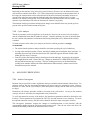
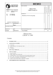
Figure 7.1 shows interactive program initiation. User input is underlined. The example applies to
VAX/VMS environments.
$ RUN <USFOS>USFOS
- U S F O S Progressive Collapse
Analysis of Frame Structures
Version 5.3 / Release 92-02-01
SINTEF div of Structural Engineering
Control
Structure
Load
Result
Figure 7.1
file
file
file
files
prefix
prefix
prefix
prefix
: ZAYAS-FRAME-HEAD
: ZAYAS-FRAME-STRU
:
: ZAYAS-FRAME
Interactive running
MARINTEK 1999-02-17
USFOS USER’S MANUAL
Running USFOS
7.5.2
7-8
Batch Execution
To run USFOS in batch mode, the user executes the supplied command procedure named BATCHFOS or
likewise. Under most operating systems, this command procedure prompts for the input file names,
generates a batch command file and submits this command file to the batch queue. On some systems, the
user will have to edit the command file manually, and submit the file herself.
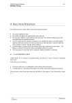
The example applies to VAX/VMS environments.
Start command procedure
$ @<USFOS>BATCHFOS.COM
X
XX
XXXXXXXXXXXXX
XXXXXXXXXXXXX
XX
X
XX
XX
XX
XX
XX
XX
XX
XX
XX
XX
XX
XX
XX
XX
XX
XX
XXXXXXXX
XXXXXX
XXXXXX
XXXXXXXX
XX
XX
XX
XXXXXXX
XXXXXXX
XX
XX
XX
XXXXXXXX
XXXXXX
XXXXXXXX
XXXXXXXX
XX
XX
XXXXXX
XXXXXX
XX
XX
XX
XX
XXXXXX
XXXXXXXX
XX
XX
XX
XX
XX
XX
XX
XX
XX
XX
XX
XX
XXXXXXXX
XXXXXX
XXXXXX
XXXXXXXX
XX
XX
XX
XXXXXXX
XXXXXXX
XX
XX
XX
XXXXXXXX
XXXXXX
X
XX
XXXXXXXXXXXXX
XXXXXXXXXXXXX
XX
X
Version 5.3 / Release 92-02-01
SINTEF div of Structural Engineering
- Analysis initiated at 92-02-01
15:05:58
Control
Structure
Load
Result
file
file
file
files
prefix
prefix
prefix
prefix
: ZAYAS-FRAME-HEAD
: ZAYAS-FRAME-STRU
:
: ZAYAS-FRAME
$ SUBMIT/LOG=<DATA>BATCH.OUT
Figure 7.2
Supply
filenames
USFOS.COM
Batch running
The command procedure generates the batch command file USFOS COM, and submits it to a background
process. Output to BATCH OUT.
MARINTEK 1999-02-17