1
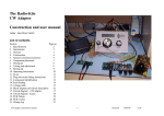
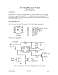
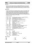
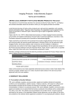
ALK-2 OPERATIONS MANUAL
MANUAL REV A
LDG ALK-2 Two-Port
Audio/Linear/Key
Switch
LDG Electronics
1445 Parran Road
St. Leonard MD 20685-2903 USA
Phone: 410-586-2177
Fax: 410-586-8475
[email protected]
www.ldgelectronics.com
PAGE 1
Table of Contents
Introduction
3
Jumpstart, or “Real hams don’t read manuals!”
3
Specifications
3
Important Safety Warning
4
Getting to know your ALK-2
4
Front Panel
4
Rear Panel
5
Pinouts
5
Block Diagram
6
Installation
7
Operation
7
Desktop / Local Operation
7
Remote Operation
7
Application Information
Examples
7
7
Technical Support
8
Two-Year Transferrable Warranty
8
Out Of Warranty Service
8
Returning Your Product For Service
9
Product Feedback
9
PAGE 2
INTRODUCTION
LDG pioneered the automatic, wide-range switched-L tuner in 1995. From its laboratories in St.
Leonard, Maryland, LDG continues to define the state of the art in this field with innovative
automatic tuners and related products for every amateur need.
Congratulations on selecting the LDG ALK-2 two-port Audio/Linear/Key switch. The ALK-2
is a versatile product, electronically switching a common 1/8” stereo jack and stereo RCA jacks
between two other sets of 1/8” stereo/RCA jacks. Although the intended purpose of the ALK-2 is
to switch stereo audio, code keys, or linear amplifier interface signals; virtually any pair of low
voltage signals can be switched between the two ports.
JUMPSTART, OR “REAL HAMS DON’T READ MANUALS!”
Ok, but at least read this one section before operating the ALK-2:
1. Connect a 1/8” stereo plug or a pair of RCA plugs to the common port, and a 1/8” stereo plug
or pair of RCA plugs to each of the two switched ports. These can be any cables with 1/8”
stereo plugs or RCA plugs installed, such as computer speakers, home stereo audio, iambic
paddles, straight keys, linear amplifier control cables, headphone audio, etc.
2. Connect at 12 volt power supply capable of supplying 100 mA to the 2.5 x 5.5 mm coaxial
power jack (center positive)
3. Press the front panel button to toggle between which switched set of jacks is connected to the
common set of jacks. The front panels LEDs indicate which port is active.
4. When a port is selected, both the 1/8” stereo jack and the two RCA jacks of that port are
connected to the common port.
5. The ALK-2 1/8” stereo plug on each port is wired in parallel with the two RCA jacks on that
port. This allows one to; for example, plug a 1/8” stereo plug into the common port, but use
RCA plugs on the switched ports, or vice versa, or any combination thereof.
SPECIFICATIONS
• Two switched sets of parallel-connected 1/8” stereo jacks and RCA jacks.
• Two circuits (stereo) switched. Red jacks are right channel, white jacks are left channel.
• Stereo 1/8” plug and RCA plugs of a given port are wired in parallel
• Maximum current 1A per circuit, 32 V.
• Remote operation possible (see Application Hints)
• Requires 12 volts at 100 mA, 2.5 x 5.5 mm jack, center positive
• If RF is transmitted through the ALK-2, keep it below 5 watts, 30 MHz, 3:1 SWR.
PAGE 3
IMPORTANT SAFETY WARNING
Never install antennas or transmission lines over or near power lines. You can be seriously
injured or killed if any part of the antenna, support or transmission line touches a power
line. Always follow this antenna safety rule: the distance to the nearest power line should
be at least twice the length of the longest antenna, transmission line or support dimension.
GETTING TO KNOW YOUR ALK-2
Your ALK-2 is a quality, precision instrument that will give you many years of outstanding
service; take a few minutes to get to know it.
Front Panel
On the front panel there is one pushbutton and two LED indicator lights. The button is a
pushbutton toggle switch which selects between the two sets of cables connected to the rear ports.
The LEDs indicate which port is selected.
PAGE 4
Rear Panel
The rear panel of the ALK-2 features three ports. Each port consists of an 1/8” stereo jack
wired in parallel with two RCA jacks. Each RCA jack connects to one of the two circuits in the 1/8”
stereo jack. When using a mix of 1/8” stereo plugs and RCA plugs, the ALK-2’s RCA jacks follow
the industry standard convention for color coding. The red jacks connect to the 1/8” jack’s right
audio channel, and the white RCA jacks connect to the 1/8” jack’s left audio channel.
One port is a common port, and the other two are the switched ports. The front panel
pushbutton alternately connects either Port 1 or Port 2 to the Common Port. The DC power jack
accepts 12 volts DC at 100 mA, center positive.
Pinouts
For each of the three ports, Port 1, Port 2, and Common, the RCA jack pinout is as follows:
PAGE 5
For each of the three ports, Port 1, Port 2, and Common, the 1/8” stereo jack pinout is as
follows:
BLOCK DIAGRAM
The following is a block diagram of the ALK-2:
PAGE 6
INSTALLATION
To install the ALK-2, attach either a 1/8” stereo plug or pair of RCA plugs to each of the two
switched ports, and also to the common port. Attach the supplied 12VDC coaxial power plug to the
2.5 x 5.5mm power jack, and apply 12VDC at 100 mA. The center pin of the DC power jack is
positive.
OPERATION
Desktop / Local Operation
When connected as shown above, pushing the pushbutton on the front of the ALK-2 selects
between the two connected ports. The LED corresponding to the selected port will illuminate,
indicating which port is the active port. An audible click will be heard each time the pushbutton is
toggled. This is the sound of the internal relay clicking.
Note that if no DC power is applied to the ALK-2, the selection defaults to Port 1, and no
LEDs will illuminate. You can take advantage of this situation to create your own “remote mode” as
shown below:
Remote Operation
For mobile installations, or installations where it is not convenient to place the ALK-2 near the
operating position, it is possible to employ a “remote” mode. This “mode” uses the fact that the
ALK-2 relays are non-latching relays, and will revert to their normally closed position when no
power is applied.
To use “remote” mode, push the pushbutton so that it is in the “in” position. Port 2 will be
selected. To remotely switch the ALK-2, you must place a switch (not supplied) in line with the DC
power to the ALK-2. When power is applied, the relays will click on, and Port 2 will be selected and
the Port 2 LED will light up. When power is removed from the ALK-2, Port 1 will be selected, but
no LEDs will be illuminated.
In this manner, if remote operation is desired, you simply have to mount an on/off switch near
the operating position, and use that switch to toggle power to the ALK-2. So long as the pushbutton
is pushed in on the ALK-2, this will allow remote control of the port selection!
APPLICATION INFORMATION
The ALK-2 may be used to switch up to two circuits plus ground between two ports for any of
a number of types of signals. Be sure to keep the signals within the absolute maximum ratings of the
ALK-2. Signals must be less than 32V at 1 amp.
Examples
• Stereo audio
• Mono audio plus composite video
• CW paddle / key
• Headphone audio
• Computer speaker audio
• Linear amplifier control voltages
PAGE 7
• Scanner or radio serial interface
• Receiver antenna selection
• QRP transmit antenna switch or T/R switch. NOTE: If transmitting RF through the ALK-2,
keep SWR less than 3:1 and power level no greater than 5 watts. Operation is not guaranteed
above 30 MHz. It is recommended not to transmit RF thru the ALK-2 while also switching a
second signal. RF isolation between the two circuits is not guaranteed.
TECHNICAL SUPPORT
The LDG Customer Support Center staff is ready to answer your product question by telephone
and over the Internet. We know that you will enjoy your product even more knowing LDG is ready
to answer your questions as the need arises.
Visit the Support Center at: http://support.ldgelectronics.com
Our website links you to the on-line Customer Support Center where you can send us a
question, do your own research in the LDG Product Knowledge Books, and read through lists of
frequently asked product questions. LDG regularly updates on-line information so the best on-line
support information is available all day and every day.
The LDG website provides links to product manuals, just in case you lose this one! When you
are thinking about the purchase of other LDG products our website also has complete product
specifications and photographs you can use to help make your purchase decision. Don’t forget the
links to all of the quality LDG Dealers also ready to help you make that purchase decision.
TWO-YEAR TRANSFERRABLE WARRANTY
Your product is warranted against manufacturer defects in parts and labor for two full years
from the date of purchase. This two-year warranty is also transferable. When you sell or give away
your LDG product give the new owner a copy of the original sales receipt and the two-year warranty
goes with the new owner.
There is no need to complete a warranty card or to register an LDG product. Your product
receipt establishes eligibility for warranty service so save that receipt. Send your receipt with the
product whenever you send your product to LDG for repair. Products sent to LDG without a
receipt are considered requests for out-of-warranty repair.
LDG does not warranty against product damage or abuse. This means that a product failure, as
determined by LDG, to be caused by the customer or by other natural calamity (e.g. lightning) is not
covered under the two-year warranty. Damage can be caused by failure to heed the product’s
published limitations and specifications or by not following good Amateur practice.
OUT OF WARRANTY SERVICE
Any time a product fails after the warranty, LDG wants to help you get it fixed. Send the
product to us for repair. We will determine what needs to be done, and, based on your prior
instruction; someone will either contact you with an estimate or fix it and contact you with a request
to pay any repair charges. Please contact LDG if you have any questions before you send us an outof-warranty product for repair.
PAGE 8
RETURNING YOUR PRODUCT FOR SERVICE
Returning a product to LDG is easy. We do not require a return merchandise authorization.
Visit the Customer Support Center and download the LDG Product Repair Form. On the Repair
Form tell the LDG technicians exactly what happened or didn’t happen and why you believe the
product needs servicing. The technician attempts to duplicate the problem(s) you had based on how
well you describe it so take the time to be accurate and complete.
Ask your shipper for a tracking number or a delivery verification receipt. This way you know the
product arrived safely at LDG. Be sure to give us your email address so our shipper can alert you
online when your product is en-route back to you. We regret that we are not staffed to provide
periodic updates on the status of repairs. We can only indicate the repair is in process until it ships
back to you. Please be assured that our staff makes every effort to complete repairs ahead of our
published wait time. Your patience is appreciated.
Repairs can take six to eight weeks, but are usually faster than this. The most recent information
on returning products for service is found at the LDG Customer Support Center.
Mail your carefully packaged repair with the Repair Form to:
LDG Electronics, Inc.
Attn: Repair Department
1445 Parran Rd
St. Leonard, MD 20685
PRODUCT FEEDBACK
We encourage product feedback! Tell us what you really think of your LDG product. In a card,
letter, or email (preferred) tell us how you used the product and how well it worked in your
application. Send along a photo or even a schematic or drawing to illustrate your narrative. We like
to share your comments with our staff, our dealers, and even other customers at the LDG website.
http://www.ldgelectronics.com/
PAGE 9