1
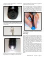
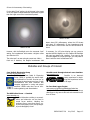
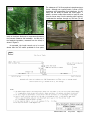
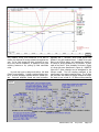
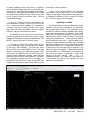
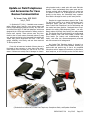
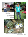
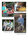
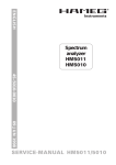
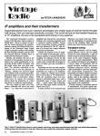
SPELEONICS 29 COMMUNICATIONS AND ELECTRONICS SECTION OF THE NATIONAL SPELEOLOGICAL SOCIETY Volume VIII #1 July 2013 Editor: Norm Berg NSS 18567 SPELEONICS is published irregularly by the Communications and Electronics Section of the National Speleological Society (NSS). Primary topics include cave radio, underground communication, cave lighting, and data collection. Contents of SPELEONICS 29 - Volume VIII #1 About Speleonics, Editor’s Notes, Executive Board, Meetings, Membership and Website 2 Communications and Electronics Section Session Minutes, June 25, 2012 3 Communications and Electronics Section Annual Meeting Minutes, June 25, 2012 3 Communications and Electronics Section Field Day Minutes, June 28, 2012 4 Cave Link Radio Communications Test by Bob Bruninga 5 An Inexpensive LED Upgrade for the Mini Maglite by Rick Bennett 10 Websites and Groups of Interest 12 Low Frequency Radio Experiments with an Experimental License from the FCC by Brian Pease 13 Update on Field Telephones and Accessories for Cave Rescue Communication by Jansen Cardy 22 Photos of Communications and Electronics Section Meetings and Field Trips during the NSS 2012 Convention 24 All issues of SPELEONICS are available online at http://www.caves.org/section/commelect/spelonic.html SPELEONICS 29 July 2013 Page 1 About Speleonics SPELEONICS is the official newsletter of the Communications and Electronics Section (CES) of the National Speleological Society (NSS). In each issue, we strive to present a variety of articles relating to electronics as applied to caving and the study of caves. Submissions to SPELEONICS can be contributed by both CES members and non-members. NSS membership is not required to be a contributor. We welcome original or reprinted articles, photographs, and letters to the editor. Submissions, in digital format, should be sent to the editor. The CES cannot publish copyrighted material without written permission of the copyright holder. Contributors are responsible for determining whether material is copyrighted as well as for securing appropriate permission. Articles do not necessarily reflect the official position of the CES, NSS, newsletter editor, or the CES officers or members. Unless independently copyrighted (©), material published in SPELEONICS may be reprinted in any NSSaffiliated publication, provided appropriate credit is given and either a hard copy or digital file made available to the author. Editor’s Notes Welcome to issue 29 of Speleonics, which is my second issue as editor. I’d like to thank those that have taken the time and effort to write up their projects so that we may all share in those efforts and benefit from them. Thanks go to our proofreaders, Danny Brass and Jansen Cardy. As a reader of Speleonics, you may be working on caverelated electronics projects that would benefit the caving community as a whole. Please take the time to write up your project and have it published so that the caving community can share in your findings and knowledge. Email the editor. You will receive an email confirming your submission. The next issue of Speleonics is planned for the month prior to the 2014 NSS Convention. The URL and email addresses in this publication are checked for accuracy prior to publication. If you find an address that is no longer valid, try doing an online search for the author or specific subject. Many authors are NSS members and are in the NSS Members Manual, which is issued yearly by the NSS. Norm Berg, Editor [email protected] (include “Speleonics” in the subject line) and 860-621-2080 before 9:00 pm Eastern Time Executive Board The Communications and Electronics Section is governed by an Executive Board consisting of four members. Elections are held at the annual business meeting during the NSS Convention. The current executive board members are: Section Chair: David Larson Secretary-Treasurer: Brian Pease Publications (Speleonics editor): Norm Berg Communications (Webmaster): Aaron Birenboim Meetings The 2013 C&E business meeting and session will take place at the 2013 NSS Convention on Monday August 5 from 2:00 pm - 5:00 pm. A field session will be scheduled during the convention. Communications and Electronics Section Membership and Website You can become a member of the CES for a period of five years by simply signing the roster at a CES meeting during the NSS Convention, or by mailing or emailing the Section Chair or Secretary-Treasurer a request to be a member and providing your contact information. The Communications and Electronics Section website is http://www.caves.org/section/commelect/drupal/ Online Cave Electronics Discussion Group To join the cave electronics discussion group and mailing list, go to http://lists.altadena.net:80/mailman/listinfo/ speleonics. Being a member of the CES does NOT automatically add you to this discussion group. You must register separately. SPELEONICS 29 July 2013 Page 2 Communications and Electronics Section Session Minutes 2012 Brian Pease, Sec/Treas 6/25/12 The C&E Session took place in the Choir Room of the High School at 2 PM on 6/25/12 following the Session Meeting. I gave a talk describing the very simple “retro” direct audio radiolocators that I have designed. The Basic-1 uses a single 8-pin dual op-amp IC and will run for days on a single 9 -Volt battery. It uses an 18” diameter loop with ~1 lb of wire. The Basic-2 adds a second dual op-amp IC to boost transmitter output and an 18” loop with ~2 lbs of wire to boost output further and improve receiver selectivity. Both are available as kits. See http://radiolocation.tripod.com for details. David Larson gave a talk on the depth sensor that was designed and assembled in record time by the Rice brothers and was installed in Chapat Cave in western Belize earlier this year. They provided an unprotected circuit board with LED status indicators and a battery hard wired to it. The pressure sensor is capable of measuring 100 ft depth and is mounted directly on the board. Data is stored in non-volatile memory that may be recoverable even if flooded. The packaging consists of multiple flexible plastic packages glued shut and placed in a non-waterproof “dry” bag filled with sand and rocks to keep it submerged. It was anchored with rope at the lowest point in the area that is subject to catastrophic flooding of ~100 depth every few years during major storms. Jim Hall used the internet to show an Inertial Measurement Unit (IMU) from Sparkfun.com. There is a tracking video on YouTube. He wondered if it might be useful for underground tracking. I thought that there would be too much drift for it to remain accurate long enough to be useful, but it would be fun to experiment with. I mentioned Bill Stone's problems with his 3D mapper at Wakulla Springs, Florida. Forrest Wilson said that British cave divers have been using dead reckoning with an electronic compass, depth meter, and impeller type water speed sensor. I think that combining an IMU, which has a an electronic gyro compass and gives roll, pitch, and yaw, all without drift, with a water speed sensor would give reasonable navigation results where there was no current. David showed very nice battery carrying cases for all sizes of round cells that keep them together and prevent damage and short circuits. The maker, PowerPax http:// www.powerpax.net, is a supporter of the NSS website http:// www.caves.org. He also showed an inexpensive white/red/ green flashlight that would be useful for surveying. He also showed a Wouxon handheld radio, imported by http:// www.powerwerx.com in CA. They are available for 144/220 MHz, 220/440, and mobile low bands for ~$120.00. They can be programmed to work on business and marine bands and are as good as more expensive name brand radios. AA battery packs are available. David also talked about developing a small, lightweight, inexpensive, 2-wire telephone for cave rescues. The rugged military copper/steel field phone wire is needed for a guideline in the caves. The idea is to have batteries only in the base station above ground, with waterproof units underground. They operate at ~1000 ohms and are more or less compatible with regular military field phones. Carroll Bassett showed a 12 Volt 6 Watt 300 lumen LED array from Lowes. It is not polarity sensitive and can be used as is or built into a housing. At this point we moved next door to the Survey and Cartography Session, where I set up a demonstration of the DistoX. I ran the PocketTopo survey software on a netbook connected to the room's projector. The DistoX sent distance, azimuth, and inclination data to the netbook via BlueTooth. The software displayed the survey line and splay shots as I took shots around the room. The DistoX is based on a (now obsolete) Disto A3, with an additional internal board designed by Beet Heeb in Switzerland that contains a 3-axis magnetometer, a 3-axis accelerometer (to sense vertical), Bluetooth link, a microprocessor, and memory. The DistoX is a great tool by itself, but when used with a Windows PDA in the cave, data is collected without error and displayed in real time. Sketching can be done right on the screen directly over the survey shots in multiple colors. the DistoX, especially because no C&E members were able to attend them. Alex Sproul is redesigning the NSS website. Aaron will talk to him about shifting our NSS website to the new site. Dave Cowan said that Higgenbothams Cave #1 would be a good site for a field trip, and that one could do a through trip by doing a squeeze then climbing a pole to exit. Communications and Electronics Section Annual Meeting Minutes 2012 Brian Pease, Sec/Treas 6/25/2012 The 2012 Lunch/business meeting of the Communications & Electronics Section of the NSS was held mid day Monday June 25, 2012 in room G-112 at the High School next to the Fair grounds at the NSS convention in Lewisburg, WV. After eating, the 4 officers Aaron, Norm, David, and I held a short board meeting. The following comments were made: The revised bylaws and the latest meeting minutes need to be posted on the section website. We need to try to get Lynn Brucker to publish her talks on Executive Chair David Larson started the annual meeting. I read the Secretary and Treasurer's reports, which were accepted. As of 5/31/12 we have $1417.66 in the treasury after paying $120.00 for 10 years of NSS web hosting. I mentioned SPELEONICS 29 July 2013 Page 3 that at David's request I had advised members who had not renewed within the past 5 years that they could now do so by email and 16 did so. I then purged the membership list of those who did not reply or was unable to contact. We had 124 active members before this meeting. 46 signed in at this meeting including 15 new members. After this meeting there are 140 active members, including 56 Hams. Communications Chair Aaron Birenboim gave a report on our website. He has converted our site to Drupal, but will try to update it to a newer development program. The NSS is changing their website and we will coordinate with them to be one of the first to convert ours. Norm Berg gave his report on the status of Speleonics, and gave an appeal for articles. His Speleonics 28, published online just before convention, is outstanding. There was no Old Business. There was some new business. David asked about the usefulness of a Facebook page, or Twitter. One concern was that members who are not signed up for Facebook would not have access. Apparently, it is possible to set security low enough that a non-Facebook user can read, but not post. There would be security and virus issues. In a show of hands, only about half of the members present have Facebook accounts and interest was lukewarm. Only 2 members used Twitter. The subject of starting a Speleonics forum on “Cave Chat” was brought up. I commented that if we did this we should shut down the existing Altadena Speleonics site so that we would only have one at a time. David said that I should send out the NSS I/O info on Speleonics whenever it comes out, because most NSS members never see it. The question came up as to whether the NSS could host our Treasury, resulting in an endowment for Website dues, our only expense. Dave Cowan described Higgenbothams #1 Cave, where we will be having our Field Day. The part we will be using has a walk-in entrance with walking passage and water in spots no more than ankle deep, and that there was off-road parking just a short distance away. Elections were held, with a motion and second to re-elect the current slate of officers, which was unanimous. The officers are: Executive Chair: David Larson Sec-Treasurer: Brian Pease Publications Chair: Norm Berg Communications Chair: Aaron Birenboim The meeting ended at 1:45 pm. Communications and Electronics Section Field Day Minutes for 2012 be heard, but were not bad. I showed how to get the most accurate location possible by correcting for bubble level errors. David had a 500 foot (150 meter) 2-wire field phone line laid out way upstream and looped back to the upstream register and had 2 phones installed on the line, one at the end. This was done by 2 local cavers who stopped by and had never seen field phones before. The base station was outside. The phones are really just simple intercoms using the 70.7 Volt line principle, with the underground phones always in “talk” mode unless the surface responds to them. They worked well, with the only complaint being low speaker audio in the cave that would require holding them to one's ear in noisy places. Of course, this is always done with normal field phones. A fun and successful day. Brian Pease, Sec/Treas On Thursday afternoon 6/28/12, 8 members gathered at Higgenbothams #1 Cave north of Lewisburg for an electronics field day. Dave Cowan suggested this cave. The cave has a walk-in entrance and a large long shallow passage under a wooded hillside, which made it ideal for testing both my shortrange Basic radiolocators and David Larson's simple homemade cave rescue telephones. Dave Cowan set up a Basic-2 beacon at the upstream register about 200 feet (60 meters) inside. Carroll Bassett and Aaron Birenboim were trained with Basic-1 receivers. Power line noise and an electric fence could SPELEONICS 29 July 2013 Page 4 Cave Link Radio Communications Test Fig 1 2 March 2013 Bob Bruninga, PE US Naval Academy - [email protected] This radio link concept should be considered as just another communications tool in the tool box for extending communications underground. For example, if other communications are possible with a base camp, then the APRS radio links can provide shorter range outward from base camp as needed to keep everyone informed. Rick Toomey, National Park Service Gary Gibula, National Speleological Society Abstract: On 2 March 2013, during an NSS Volunteer weekend at Mammoth Cave, a radio test was conducted that extended UHF communications range to nearly a mile underground. The system uses ham radio UHF text messaging and position reporting APRS radios (Figure 1) that can use each other as automatic relays. A string of 14 radios provided continuous text/position reporting communications anywhere along the mile to the surface. Cavers carried maps with a lat/long grid and could manually enter their position and send simple text messages. Establishing the network was as easy as walking to the end of each radio’s range, and then backing up a few dozen feet to regain contact and place a walkietalkie on a rock… Then continuing. See http://aprs.org/ cave-link.html variety of factors to be tested. This system could also be integrated with field-wire where it is easy to run great distances for some links. Although the test originally was conceived to test a very simple network consisting of simply 14 people carrying relay-capable walkie-talkies, these radios (Figure 1) are the latest technology and not as prevalent among ham radio operators as the nearly 10-year-old mobile radios. To get enough radios for the test, we ended up using 8 of the mobile radios carried in metal boxes and only 2 of the walkie-talkies (shown here inside protective PVC pipes – Figure 3). Fig 2 Background: Although typical 400 feet or so UHF radio range has not been impressive to cavers in the past, this new capability to automatically link up to 14 such hops into a continuous network for text and position reporting could be useful in many cave projects as suggested in Figure 2. Digipeaters: We use this term to refer to the digital repeating function of these radios. Both the Kenwood THD72 walkie-talkies and the boxed D700/D710 radios, as Fig 3 The purpose was to test the viability of using APRS VHF/ UHF walkie-talkies for distance communications in cave passages by taking advantage of the radio’s internal hop-by-hop linking capability for digital text messaging. Links up to 7 or 14 hops long are possible, which can extend the usual very limited 100’ to 500’ radio range by an order of magnitude or over a mile, depending on a SPELEONICS 29 July 2013 Page 5 shown here, are capable of digipeating. See http:// aprs.org/cave-link.html Internet Link: This ham radio data networking capability can be automatically linked into a global network by any radio that is also connected to a laptop or PC and has access to the internet. For this test, we set up a laptop and radio in the Ranger’s “break room” about a half mile from the elevator shaft. A digipeater at the top of the elevator linked the data to John (KG4LVA) and the internet. John was designated as the topside point of contact with NPS. For example, NPS personnel could view the progress of the test, and positions of the participants on any PC via the internet on the http://aprs.fi site. This site can give anyone anywhere a view of what is going on with this network, including all the way down into the cave as viewed from above. Base Camp Team: Josh (KY4JME) set up a base camp operating position in the Snowball Room and had connectivity to the topside APRS network via the one digipeater at the top of the elevator and one about 100 feet into the Snowball room from the base of the elevator. This convenient location gave us an area to organize and debug our equipment. We also had HF radio equipment available, but did not get to test it due to the time it took to unravel some of the initial bugs and confusion during setup. Cave Team: The cave team, led by Bob (WB4APR) and Ranger Toomey, with assistance from Gary Gibula of the NSS, proceeded from the Snowball Room down Cleveland Avenue, monitoring signal strength from the Snowball Room and setting down link radios as needed. This being our first experience with this equipment underground, a few hours were wasted trying to figure out why performance was so poor after the second digipeater from the Snowball Room. Eventually it turned out that that Fig 4 digipeater was m i s co n f i g u r e d and was not relaying anything beyond it. After that was finally resolved, the team proceeded as far as communications permitted until we ran out of radios several hundred feet short of the Carmichael entrance. On the second day we returned to extend the link with 3 more ra- dios from where we left off the day before to complete the entire 1 mile path from the Snowball room, out the Carmichael entrance, to the above ground network. You can see the topside digipeater in the foreground (Figure 4) and the typical handheld in the hands of the author. HF Test Team: This team lead by Ralph (KG4CSQ) was to remain topside and test conventional vertical penetration communications on HF. But with the cold and initial difficulties with the APRS setup, this test was not conducted. Un-wired Test: After the success of the initial 1 mile test in Cleveland Avenue, we had planned to do a similar test into an area of the cave that had no installed lighting or other wiring that may have acted as conductors of RF energy. The plan was to retrieve at least 8 of the digipeaters from Cleveland Avenue and then repeat the test into the Violet City entrance proceeding into the Main cave. Again, we ran out of time and did not conduct this test. This team would have needed personal lighting and more conventional caving gear. Vertical Conductor Test: This test was planned to test the viability of RF conduction in the vicinity of the abandoned well pipe in Cleveland Avenue to see if such a metallic conductor could enhance VHF radio vertical penetration. Again, this test was also not conducted due to lack of time. Operations: Data transfer consists of position reports and text messages. Text messages can be up to 64 characters long in the protocol, but are restricted to 45 so as not to overflow the display width of some older walkietalkies (D7’s) which have a limited display screen. Position data is broadcast to all, and messages can be sent as bulletins to all in the network. Additionally, individual messages can be sent point-to-point to only the intended recipient, if needed. Generally, the real value of messaging in this network is the ability to communicate with bulletins, so that everyone in the cave gets a copy and can see what is going on. The radios automatically transmit their GPS positions when above ground, but for this application, the operator has to manually enter the LAT/ LONG coordinates from a hand-held map as he goes along or whenever he wants to report a specific position. It is simple to overlay a grid on any map in advance of any cave activity. The grid does not even need to translate to real LAT/LONG unless you want the topside viewers to see the actual underground positions relative to the usual Google maps. Paths: The way these digipeaters work is that they will relay any packet that they have not heard before and when they do relay it, they will mark it as having been used so that they do not duplicate that packet again. In SPELEONICS 29 July 2013 Page 6 the past, to go 14 hops, it would take 14 unique addresses, which would make the packet very long. What APRS does in this case is use the generic address of HOP and then includes a hop counter. The address begins as HOP7-7 but after each digipeat, the final “7” (called the SSID) is decremented. This way the packet can go 7 hops before that packet is used up (down to HOP7-0). The initial 7 is included so that the recipient can tell how many hops the packet started with before it reached 0. To get beyond 7 hops, we need to add another HOP7-7 field and actually transmit each packet with a dual address of HOP7-7,HOP7-7. Adding this second field allows us to double the number of hops to 14 hops but adds additional bytes of overhead to every packet, which reduces instantaneous link probabilities by about 10%. After the first one is decremented 7 times to HOP70*,HOP7-7 the used up portion of the address is marked with a * and then the remaining path (now with an additional 7 hops) is used. This could be extended to a third address field to get 21 hops, but the decreasing probabilities of success suggest a point of diminishing returns. To make sure the packet can go an additional 2 hops to an internet station once it gets topside, we add an additional WIDE2-2 path on the end. The global topside network responds to WIDEn-N, where usually a value of N no larger than 2 is used to limit loading on the global network to only the 2 nearest digipeaters. In summary, the resulting path used for this test was HOP7-7,HOP77,WIDE2-2. Digipeater Settings: These digital radios have literally dozens of setup parameters for proper configuration for this test and it was this complexity that caused us to lose several initial hours during the test due to one improper setting in one radio. And it is nearly impossible to test these radios topside because they would all be able to hear each other and would shortcut from the start to the end in one hop. We have used the radios topside with 14 hops to actually cover the 2000 mile distance from Georgia to Maine along the Appalachian Trail, so you can see how impossible it would be to test the radios topside when they can all hear each other over large distances. The best we could do was put dummy load antennas on them and try to simulate the test indoors, but trying to de-tune radios capable of 100 mile links down to 100 feet is problematic. The slightest leakage can drastically extend the range and the digipeaters get bypassed without knowing it. Anyway, the detail settings are beyond the scope of this paper, but are summarized in detail on the project’s web page: http://aprs.org/cave-link.html Test Results: The initial test was conducted in the Cleveland Avenue area of the cave, as shown in Figure 5, entering from the Elevator and Snowball Room on the right. The light blue station numbers show where the digipeaters were placed. During the initial test, we made it as far as #10 from the elevator entrance before we ran out of radios. The next morning, just to complete the original 14-hop goal, 3 of the radios (re-numbered as #13, #12, and #11) were set starting at the Carmichael entrance on the left below to get to the same spot as #10 the day before. Fig 5 SPELEONICS 29 July 2013 Page 7 Grid Reporting: Notice the grid (Figure 5) to the nearest hundredth of a minute of Lat/Long overlayed on this map. This allows posiFig 6 tion resolution to the nearest 60 feet or so. For example, the location of digipeater number 7 is about 37° 10.18N and 86° 05.17W. But for the purpose of reporting over the scale of this map, only the last two digits are actually needed 18N/17W. Path Length: The longest link on UHF was almost 700’ long. The two histograms shown in Figure 6 count the approximate number of path lengths for each distance we were getting on VHF and UHF. These ham radios can do either. The initial test was conducted on VHF but was complicated with lots of mistakes and learning so the data is suspect. But once we had the bugs worked out, the test was quickly done with UHF, and it appeared that UHF was slightly better with greater numbers of longer lengths. VHF/UHF Antennas: The radios used simple wire whip antennas. For the walkie-talkies, it was just the standard rubber-duck antenna that comes with the radio. For the boxed digipeaters, it was either a 6” or 20” piece of wire for UHF or VHF. For troublesome links in some places, a Fig 7 handheld beam antenna, as shown in Figure 7, may be used where appropriate and worth the extra setup. These beam antennas are designed to mount on any standard camera tripod. Such an antenna would not generally be carried while walking and only used at the fixed vertical link locations. Power: The Walkie-talkies operate at 5 Watts and the mobile radios can operate at up to 50 Watts. We operated them at the 10 Watt level to save batteries. Generally we think that higher power and higher gain antennas do not gain the same amount of benefit as they usually do topside. This is because the path length is limited more by cave geometry than signal strength. Normally, radio range is doubled by a 4 times increase in power. But in the cave, the biggest loss of signal is not due to “range” but to twists and turns in the passages and absorption along the walls. We think the added bulk of higher power radios and gain antennas for only a bit more range is not worth the bulk compared to the simple 5-Watt walkie-talkie. Though this is an excellent area for additional testing. HF Hardware: The HF hardware was going to be a pair of FT-817 radios with attached KPC3 packet TNC’s wherever a vertical link might be useful. These would use dipole antennas made with ½ wave length wire from 8 to 65’ long. A microphone could be used for coordination, but the attached data modems provide the data link. The TNC’s are set up to beacon and to be digipeated by each other so that we could know when Fig 8 they are decoding each other without actually having to have laptops at each location. If these were to actually be used to extend the APRS network, each HF radio would also need a UHF walkie-talkie. Emplacement Procedures: To keep the test simple and with minimum impact, no test equipment was included in the test. The length of each link was simply established to achieve at least 95% reliability (19 out of 20 packets successfully received). This is accomplished by setting the base camp beacon rate at one packet every 12 seconds and then just walking away until the packets were not decoded. Then backing up to where the signal was strong enough to copy all packets reliably. If we get 19 out of 20 (or 95%) reliability on each link, then this multiplies to an overall 70% reliability end-toend figure per packet over a 7-hop length. This would drop to about 50% over a full 14-hop length. This link reliability is accounted for by transmitting packets redundantly. For example, messages are transmitted once a minute for 5 minutes. This redundancy improves the probability of reception to nearly 99.8%. Similarly, position reports can be transmitted a few times to improve the overall reliability. The maps carried by all radio personnel have a lat/long grid so that operators can manually enter their coordinates and properly appear on any PC maps viewing the test on the internet. Each digipeater also reports its own position (as manually entered by the operator) so that everywhere in the system the locations of these devices can be seen. SPELEONICS 29 July 2013 Page 8 Follow-up UHF Testing: Although these ham radios are expensive ($500), they operate in the same UHF spectrum as the inexpensive $20 FRS radios available everywhere. This makes it easy for any cavers to test the viability of individual links for such a system without a major investment in the ham radios or needing a ham license. But once the number of UHF links is determined using the simple $20 FRS radios, then it can give an idea of the value of bringing in the Hams with their text/data radios. The ham radio experimenters welcome additional experiences and feedback from cavers with UHF underground experience in all types of passages. Just remember, now you can link these short range links together with APRS. To conduct a test, you only really need two FRS radios. Start at the entrance with one radio and the other carried to max range for the first passage. Then keep a radio at that location and leapfrog a radio to the end of the second link. And so on up to 14 hops. Once these places are known, then future expeditions in this cave could use the APRS radios to provide continuous texting and position reporting communications along the entire path. The experimenters welcome and need additional data on the viability and length of these links as tested by actual cavers and opinions on whether such a system would be useful and in what circumstances. In particular, one place where this kind of communications might be valu- able is through areas where it may take an hour only to go a few hundred feet, and spooling field wire is not practical. The radio link might get through this tough part easily and then multiple hop extensions can greatly extend communications from topside to the caving team. For very deep-penetrating expeditions, communications back to the entrance might not be needed and other classical HF vertical links can make contact with in-cave base camps and then from there the UHF system can go out another 14 hops in any direction. The key will be accumulating enough in-cave information from experienced cavers on the viability of UHF in the hard spots and smaller/wetter passages than the subways in Mammoth Cave. Send in your reports to the above web page author. If this system proves viable, it can be very practical for caving expeditions. Caving teams can either recruit local ham radio operators to bring their own gear or NSS members might want to get their own ham licenses. Ham radio no longer requires learning the Morse code and getting a ham license is about as easy as getting a drivers license. Just study the materials and take the test. For more info see http://arrl.org SPELEONICS 29 July 2013 Page 9 An Inexpensive LED Upgrade for the Mini Maglite Rick Bennett [email protected] I can remember the first Mini Maglite I bought. I looked up the history of the Maglites on www.maglite.com to help jog my memory; the AA Mini Maglite came out in 1984 and that is about the same time I can remember buying one. At the time it was the first really “small” and bright flashlight for camping, backpacking, caving, etc. We also found out they were nearly indestructible. And almost 30 years later they still make them! No, I don’t still have my first Mini Maglite, but I do have one that is well over 20 years old and has been on many caving trips. It even still has a lanyard on it with a carbide lamp tip cleaner on it. tronics. Cree has become a large manufacturer of LEDs for the lighting industry and has some extremely high output LEDs, but most of them come in surface mount. Anyway, these 5mm LEDs are only $.22 apiece, so figuring why not, I added a few to an order from Mouser (I order electronic parts for various projects on a regular basis). When the LEDs came, I put one in my modified Maglite and wow, I was pleasantly surprised. The LED was actually brighter than the original incandescent bulb in the Maglite. Since then, I have upgraded all of the working Maglites I have around the house with these Cree LEDs. How to Make the Mod The Mouser Electronics part # for this LED is 941C503CWANCBADB152. Of course, the shipping will trump the cost of just 1, but hopefully a person can do a group buy to share the shipping cost. So as I said, modifying an AA Maglite for LEDs is pretty easy. Here is how. The first step is to take the head off of the Maglite and remove the bulb. Since LEDs have a positive and negative lead (the “anode” and “cathode”), you have to determine the polarity of the bulb socket. Using two small pieces of #24 solid wire (or something similar) and a multi-meter, this is fairly simple. Insert the wires into the sockets for the bulb, and using the voltage setting on the meter determine the polarity. Trying LEDs When useable white LEDs first showed up on the scene about 10 years ago or so I started trying different LED replacements in one of my Mini Maglites as a “test bed”. The standard 5mm LEDs are fairly easy to retrofit into an AA Mini Maglite. Unfortunately the early white LEDs were not very bright. The battery life was almost forever with the LED, but you paid the price in light output. Every so often I would upgrade the LED to something newer and brighter, but until recently they did not make a very bright flashlight. Recently I came across some Cree 5mm white LEDs that were quoted to be 35,000 millicandelas at Mouser ElecSPELEONICS 29 July 2013 Page 10 I marked the negative terminal with a “-” scratched into the plastic ring using a pick. It may take a little rocking back and forth to get the LED to seat all the way into the socket. Before assembling the light, you will need to enlarge the hole in the Maglite reflector. I recommend taking the head apart and taking the reflector out. Be careful not to scratch the reflective surface. With a 3/16” drill bit, carefully enlarge the hole on the reflector. Clean the burrs from the hole using a small hobby knife. The LED needs to have the leads “shaped” to fit. Trim both leads to 1/4 inch. Using small needle nose pliers, bend the leads inward so they are about 1/16 inch apart but still parallel. The last step is to reassemble the head and reinstall it on the flashlight. Some Testing The LED has a flat spot on the negative or cathode side. Plug the LED into the socket with the correct polarity. If good batteries are in the Maglite, the LED should light. I don’t have any fancy test equipment for lighting. But I wanted to verify my visual observations that the modified LED Maglite looks brighter. So I put together a simple light meter using a photocell and a multi-meter. I used a Maglite with fresh alkaline batteries and switched between the LED and a Maglite bulb. I tested the brightness at the widest “flood” setting on the flashlight and the narrowest “spot” setting. There is one thing that needs to be pointed out: the reflector in the Maglite was designed for the Maglite bulbs, but not for an LED. So the pattern of the lighting from the LED is different than the pattern from the incandescent bulb. For the wide “flood” setting on the flashlight with an LED, the brightest area of the pattern is in the middle, but for the incandescent bulb the middle is dark with a bright ring around the center dark spot. I had to measure the light levels somewhat differently with each pattern. SPELEONICS 29 July 2013 Page 11 So here is the summary of the testing: For the wide “flood” setting, the bright area in the center of the LED pattern indeed measures significantly brighter than the bright area of the incandescent pattern. Pattern of Bulb Pattern of LED However, with the flashlight set to the narrowest “spot” setting, the incandescent bulb creates a brighter center spot than the LED. The other test I ran was a simple current test. With a fresh set of batteries, the Maglite incandescent bulb draws about 330 milliamperes, where the LED draws only about 50 milliamperes. So the incandescent bulb will last about 6 hours where the LED will last about 40 hours. In summary, for $.22 plus shipping you can convert a standard AA Mini Maglite to a very useable LED flashlight with very long battery life. However, if you want to use your Mini Maglite as a bright spot light, you may want to leave it with the stock incandescent bulb. Websites and Groups of Interest Cave Radio & Electronics Group bcra.org.uk/creg/index.html The UK-based Cave Radio & Electronics Group (CREG) is probably the world's leading organisation of its kind. Its aims are "to encourage the development and use of radio communication and other electronic and computer equipment in caving and related activities". CREG's main role is one of information gathering and dissemination. The NSS Online Forum — Cavechat www.cavechat.org Technical discussions relating to communications and electronics can be found in several forum sections, including the equipment forum, cave rescue forum, survey and cartography forum, and photography and videography forum. CaveSim crawl-through electronic cave simulator www.cavesim.com CaveSim is an electronic caving experience for beginning and experienced cavers of all ages. In-Cave Data Logger Project www.caves.org/grotto/ccg/datalogger/index.htm A project of the Central Connecticut Grotto to develop a data logger to log caver traffic and environmental conditions in caves. SPELEONICS 29 July 2013 Page 12 Low Frequency Radio Experiments with an Experimental License from the FCC Brian L Pease Experimental License WG2XPJ, Amateur Extra W1IR, NSS Fellow 7476, Electronics Engineer 45 years, Owner of Thru-the-Earth Radiolocation 431 Westford Road; Milton, VT 05468 [email protected] ABSTRACT This year I obtained an Experimental Radio License to allow me to legally conduct experiments on two low frequency bands with relatively high power. Amateur radio operators in the US may eventually be able to operate on the 630 meter (472 – 479kHz) and 2200 meter (135.7 – 137.8kHz) bands which have both been approved by the International Telecommunication Union. A number of Amateurs in the US have been legally experimenting on these bands for several years. These bands are of interest to cavers for through-the-earth communications. The licensing process involved submitting an application to the FCC including my qualifications, the reasons for needing the license, frequencies, emission types, power levels, locations, and antennas, along with documents describing the proposed experiments and a fee of $60.00 US. Everything was done online. I proposed to test low profile, long wire antennas (earth current antennas to cave radio folks) and compare them to traditional verticals. My license, WG2XPJ, arrived in May 2013. I have erected a full size (265 meters) dipole 2 meters above the ground and constructed a 100 Watt ClassE amplifier (>95% efficient!) for the 630 meter band. I have measured the maximum 1 Watt Effective Radiated Power (ERP) permitted by my license. To date, I have a strong daytime signal at 65 miles (105 km), and over 400 miles (644 km) at night, both with ordinary CW transmissions. I plan to test on the 2200 meter band, running about 300 Watts for 1 Watt ERP and would like to do some Through-the-Earth tests, if possible, using shorter portable antennas. Why Get an Experimental License? Apart from cave radio, what got me interested in low frequency Above-the-Earth Radio was a notice from my local ham club describing a scheduled CW transmission from SAQ in Grimeton, Sweden on 17.2kHz on 12/24/12. The station was originally commissioned in 1924, and uses the only remaining operational Alexanderson rotary alternator (Figure 1) to transmit up to 200 kilowatts CW into the original giant VLF antenna array. No tubes or transistors in this baby! I quickly put together a tuned loop antenna and receiver, and caught them tuning up at 2:30 AM EST in perfect quiet winter conditions. They registered 5-6dB above the noise on my old Rycom Selective Level Meter and gave near perfect CW copy with a note as clean as any modern transmitter. See http://www.alexander.n.se for details of this amazing World Heritage Station. This prompted me to design and build a broadband active low frequency receiving loop antenna and an active vertical dipole, both of which function, but are still works in progress. A number of years ago, a local ham Fritz Raab, W1FR, helped organize the ARRL 500kHz Experimental Group. They obtained a FCC Experimental License to operate as a group in the 495510kHz (630 meter) band no longer used by maritime interests. Their call signs are WD2XSH/xx, with xx being the number assigned to a specific station. They have been conducting organized beacon operations and 2way contacts. The ITU recently authorized ham use of 472Fig 1 479kHz worldwide, subject to local approval, so the XSH operations have moved there. A number of hams have independently obtained Experimental Licenses to operate in this proposed ham band and also in the possible 2200 meter ham band on 135.7137.8kHz, which is of great potential interest to cave radio nerds. SPELEONICS 29 July 2013 Page 13 How I Obtained My Experimental License Fig 2 I decided that I was probably qualified enough to obtain my own license, so I visited the Electronic Code of Federal Regulations at http:// www.ecfr.gov to read about the experimental radio service, which is Part 5 of Title 47. The Scope of Service (Figure 2) pretty much covers anything one might wish to do! Another nice find was that one could change equipment, antennas, and emission types, within the scope of the original license, by simply adding them to the original online application yourself (Figure 3). If you feel that you need some help, Warren ([email protected]) has applied for half a dozen experimental licenses for himself and others with 100% success. He said that he is willing to help. Next, I visited FCC's Experimental Licensing System at https://apps.fcc.gov/els to see what was required. The homepage has a link to a PDF User Manual which describes each step, all of which can be done online. First, one fills out form 442 for a new License. The first hurdle is that you must enter your FCC FRN number, which hams already have, but others will have to obtain. The form is straightforward until it asks for an attachment describing exactly what you propose to do, how long it will take, and how it will benefit the world. Figure 4 is my attachment. Next, it asked for a description of my transmitting equipment, some of which is homebuilt. Next I had to add antenna details such as geographic location, height (for aircraft) possible mobile operation, etc. Then I had to give frequencies of operation, transmit power, Effective Radiated Power (ERP), frequency tolerance, etc for Fig 3 each band requested. I used the NEC4 antenna program to estimate the radiated ground wave Electric field at a distance off the end the dipole using my ground parameters. ERP can be derived from this value. Now came a really fun part: entering the emission designators for each form of modulation that I wished to use. In some cases there is more than one answer! For Morse code, bandwidth depends largely on whether the SPELEONICS 29 July 2013 Page 14 Fig 4 Low Profile LF and MF antennas Proposed Research and Experimentation Brian Pease, W1IR, Amateur Extra 2/27/13 Most radio amateurs assume that verticals are the only practical antennas for long distance communication at low frequencies. Simulations of antenna performance in the proposed 135.7 – 137.8kHz and 472 – 479kHz Amateur Radio Bands show that resonant horizontal dipole antennas located very close to the ground (but with no ground system at all) have significant vertical E -field radiation and can potentially perform nearly as well as a 15 meter (50 ft) top loaded vertical with a ground system. This is especially true in locations with poor ground conductivity where vertical antennas tend to perform poorly. The dipoles are directional, with maximum vertical radiation off the ends. In one simulation, a resonant dipole at 475kHz positioned 2 meters (6.5 ft) above the ground with ground conductivity of .002 S/m created a vertical Electric field off its ends only about 3dB less than the 15 meter vertical mentioned above. Even a dipole 2 inches above the ground radiates significant energy in simulation. The Dipoles are also broadband. The 475kHz dipole 2 meters off the ground has 30kHz bandwidth at the 2:1 SWR points, far wider than the proposed band. Resonant dipoles close to the ground are much shorter than in free space, ~220 meters (715 ft) for the dipole 2” above ground vs ~315 meters (1033 ft) in free space. They can be shortened further by adding capacitive loading to the ends, loading coils, or with a matching network at the center. For very short antennas, the ends can be grounded, but this can add considerable loss especially where ground conductivity is poor. I think that if these LF and MF bands become reality, these simple low profile antennas could allow many hams (who have some space) to experiment with LF or MF that otherwise would not attempt it because of the hassles and expense of a tower, ground radial system, top-hat, and tuner. These antennas can be run along the top of a fence or attached to trees while standing on the ground. Cheap Aluminum electric fence wire and insulators can be used. I have the space to conduct some experiments. I propose to attempt the following: Simulate several more antenna configurations, heights, and ground conductivities for each band using the NEC4 method of moments program. Measure the actual conductivity of the ground where the antennas will be erected to better estimate expected performance. Erect a limited number of antennas (one at a time in the same location), tune them, and measure and record lengths, bandwidths, etc. All antennas will be “in the woods” well below the existing tree canopy. Transmit a carrier of known power from each antenna and measure the vertical field strength off the ends and sides in the far field several km away, using a shielded Fairchild calibrated loop antenna and a Rycom portable Selective Voltmeter with a preamp. Based on the simulations, the initial transmit power will be adjusted for an expected EIRP of ~1 Watt or less. Compare measured to simulated performance and select the best designs. If possible, use existing signal “grabbers” linked to the internet, or direct contact with other experimental stations to demonstrate long distance communication. Possible modes are CW, PSK31, and the narrow band weak signal FM digital modes created by K1JT, especially WSPR and his new JT9-1 mode designed especially for LF/MF communication. I have the following equipment on hand now: Materials to erect the antennas. A homebuilt 25 Watt Class E amplifier for 472-479 kHz. A Hafler P3000 300 Watt linear audio amplifier suitable for 135.7-137.8kHz. An HP3586C Selective Level Meter as a receiver, with an RF output suitable to drive the amplifiers for the field strength testing. A homebuild active loop antenna to receive these bands to select clear channels. A Trimble GPS frequency standard to lock the 3586C frequency to a fraction of a Hz accuracy. A Fairchild calibrated loop antenna for the field strength measurements. A battery operated Rycom 3121B Selective Level Meter with preamp for field strength. Equipment to assemble an RF impedance bridge for tuning/measuring the antennas. An Advantest R3361A Spectrum Analyzer for measuring harmonic output of the amplifiers, etc. An IC-703 as a low level (SSB) signal source for the digital modes. A laptop computer with software to send and receive the digital modes. I will need to fabricate a ~100 Watt amplifier for 472-479 kHz, with adjustable power level, and a forward/reverse RF power meter that covers both bands. I will need to assemble and calibrate the RF impedance bridge. SPELEONICS 29 July 2013 Page 15 keying is “hard” or “soft”. 15 WPM Morse code would be 62H5A1A, with 62.5Hz being the bandwidth for hard keying. The “A” represents human reception. Is it OK to send slower CW without a new designator? (probably OK). For slow CW, QRSS-3 (3 second dots) is 1H67A1B, where B represents machine reception, but the receiving ham is really looking at dots and dashes on a “waterfall” display to read the code. Is this human or machine? There is advice on the internet and I did my best. Fig 5 Any exhibits can be attached to the form, such as photos of the antennas, details of the experiments, etc. After review, the application was sent at the press of a button. Amendments can be added later. Now, one proceeds to form 159 to pay the $60.00 filing fee, credit cards accepted. The typical wait is 3 weeks, but mine got lost on someone's desk. After 9 weeks I finally emailed the Experimental License Branch directly. This seemed to get things moving as my license (Figure 5) was granted 1 week later, with the callsign WG2XPJ. Setting Up a Station on 630 meters My first step was to install a full-size dipole antenna in the trees along the property line of our 10 acre house lot. I mounted electric fence insulators 2 meters up, then cleared branches between them. I then pulled aluminum electric fence wire through the insulators from a ¼ mile reel (402 meters) purchased at Tractor Supply (Figures 6 & 7). Details of the final tuned dipole are shown in Figure 8. To save hours of time tuning and matching the antennas, I purchased an AIM-UHF Vector Impedance Analyzer from Array Solutions. It can measure impedance, SWR, etc at the end of any length of transmission line from 5kHz to 1GHz. I use it with a netbook computer for control and display. Paul Jorgenson has demonstrated a version of this analyzer at previous C&E Sessions. It is capable of professional accuracy. I initially used it diSPELEONICS 29 July 2013 Page 16 Fig 6 The resistance of 131 Ohms required a step-down transformer. Although not a perfect match, I chose a 2.25:1 impedance ratio transmission line transformer for efficiency and the ability to handle the 100W power. I added a common mode choke mainly to keep RF noise from the house away from the antenna while receiving. I calibrated the analyzer through my 250 foot (76 meFig 7 rectly at the dipole feed point to resonate and measure the resonant resistance and bandwidth. An AIM plot of the feedpoint impedance, measured from the shack, is shown in Figure 9. As expected, the length turned out to be much shorter than the 315 meters predicted for free space. Fig 8 SPELEONICS 29 July 2013 Page 17 Fig 9 ters) feedline, choke, and transformer to be able to monitor the antenna for tuning variations throughout the year. So far, little change has been noticed from very dry to very wet soil conditions. It appears to be a good receiving antenna so far, picking up little man-made noise. My next step was to design and build a 100 Watt Class-E power amplifier. I chose a push-pull design similar to an audio frequency amplifier built for another project. Push-pull amplifiers cancel out even harmonics, especially the 2nd harmonic, which would appear near 950kHz in the AM broadcast band. I added a low pass filter to the 475kHz design, and matched the output to 50 Ohms for direct connection to my feedline. A schematic of the final LT Spice simulation is shown in Figure 10, along with some waveforms in Figure 11. MOSFETS from the LT Spice collection can be substituted for the Infineon model. The 0.93 coupling coefficient of the transformers is the actual measured value. The 50 Ohm low pass filter was difficult to design because the amplifier wants to see a load of ~25 Ohms while presenting Fig 10 SPELEONICS 29 July 2013 Page 18 an output impedance close to zero Ohms. I ended up with a Chebychev design using the free ELSIE filter design program. Keying the drive signal will cause serious key clicks, and could damage the MOSFETs, so I ended up keying the full amplifier current, which can be made to turn on and off slowly to avoid the clicks. This was another difficult design. Figure 12 is a photo of the 100 Watt amplifier. The actual schematic is shown in Figure 14 (at end of article). I had sine wave drive available, so I converted it to a square wave with an exact 50% duty cycle. Other duty cycles will cause high MOSFET currents, reduced efficiency, and high second harmonic output. The MOSFET driver IC improves the rise times further and provides up to 4 Amps peak current to rapidly charge and discharge the large gate capacitance of each MOSFET, reducing their time in the linear region. Q3 spends a brief time in the linear region on purpose (to avoid key clicks) while switching the amplifier on and off for CW modulation. The Drive Latch circuit will cut off RF drive to the MOSFETs if the 12 Volt fixed supply is interrupted or it's voltage drops below 7VDC. This protects the MOSFETs from 120 VAC power interruptions during unattended operation, which might do bad things such as alter the drive frequency. The amplifier is designed to operate from a 12-14 Volt battery. If the battery drops much below 7 Volts, the MOSFET drive voltage may not be high enough to keep them out of the linear region, resulting in failure. I have tried to measure efficiency (RF Output/DC input power), but my test setup is not yet accurate enough. In any event, nothing seems to even get warm, so I assume the efficiency is 95% or better at 100 Watts out. The fan appears to be unnecessary! Operating on 475kHz My first task was to make some field strength measurements in the far field, especially off one end where the strongest signal should be. This would allow me to calculate the maximum Effective Radiated Power (ERP), which uses a dipole pattern as a reference. First, I used Google Earth to locate points roughly 1 km away in different directions where I could park next to a road while making each measurement. I noted angle and distance from the antenna in each case. I used my Battery operated Rycom 3121B Selective Level Meter with a Fairchild calibrated shielded loop antenna to measure the electric field strength (Figure 13). A transformer matched the 50 Ohm loop to the 5000 Ohm input of the Rycom, providing a big boost in sensitivity. I operated the transmitter at 100 Watts. At d=5244 meters range, directly off one end of the dipole, I measured a vertical field strength of Ez=1.45 mV/mtr. ERP = (Ez * d) squared/49.2 Watts = 1.17 Watts ERP, very close to my 1 Watt License limit, and far more accurate than most hams who only estimate it. Fig 11 SPELEONICS 29 July 2013 Page 19 The low Dipole is not an efficient radiator (1Watt ERP for 100 Watts in, keeping the earthworms warm and happy), but it is broadband, cheap, and does not require a tower or a tuner. It works best over poorly conducting ground. The traditional vertical antenna works best over good conducting ground. Verticals require an extensive ground radial system, a large inductive tuner, plus a capacitive top hat to have better efficiency, and are extremely narrow band, requiring frequent re-tuning. In one daytime test, my signal (off the end of the dipole) at 65 miles (105 km) range was about the same as that from another station running the same power to a 25 foot (8 meters) vertical over a ground plane at 55 miles (88 km) range. At night I have a report from a person in PA, over 400 miles (644 km) away, who could copy me directly by ear. I can't wait until the quiet winter months! Fig 12 2200 meters and Future Experiments Fig 13 The items below are possible future experiments: My next antenna task, before winter, is to install a wire 2 meters off the ground to allow me to extend the south end of my dipole to resonate on 2200 meters, 137kHz. I do not have the space to extend the other end, so I plan to operate this ¼ wave wire against a ground formed by my nearby off-season in-ground swimming pool. It has a plastic liner, but a lot of underground surface area with 18000 gallons (66,000 liters) of quite conductive water. Model and build a tuning network to allow me to use the existing dipole on 2200 meters. I have purchased a Hafler 3000 audio amplifier, which should produce at least 300 Watts at 137kHz. I might try modeling the 630 meter dipole with this extension to see what it can do on 630 meters. Move the 630 meter dipole higher off the ground, but what a pain! Construct a transverter for a ham rig to be able to operate on narrowband digital modes other than slow CW. SPELEONICS 29 July 2013 Page 20 Fig 14 SPELEONICS 29 July 2013 Page 21 Update on Field Telephones and Accessories for Cave Rescue Communication By Jansen Cardy, NSS 50665 July 1, 2013 In Speleonics 27 (2011), I detailed some communication devices being used by cave rescue teams and training organizations around the country. My main article covered the NATO TP-6N field telephone which was designed in the 1970s and remained in military service in Europe until recently. These phones were first introduced to the US cave rescue community almost 5 years ago, and are continuing to be integrated with existing US -made field phone equipment and wire. Their size, weight, reliability, voice clarity, and cost have made the TP-6N a popular item. Even with at least two hundred of these phones in the hands of cave rescuers, no more than a few equipment failures have occurred per year as far as I am aware. Problems are mostly due to damaged or deterio- rating handset cords, a weak point with most field telephones. I have accumulated many spare parts and encourage anybody with a defective phone to contact me for repairs or advice. The TP-6N supply line is now beginning to slow down, but fortunately many organizations had the foresight to stock up with extra phones. Despite the rugged handsome appeal of the TP-6N, I’ve also been working on a sleeker pocket-sized communication option. Last year I sent my first batch of these “Pocket Field Telephones” out for field testing and the results have been positive. I designed them to supplement the existing field telephone system – not completely replace it (though they could if you really needed to). This pocket phone is best suited for an Underground Branch Director, Evac Task Force leader, Comms Task Force leader (for backup and troubleshooting wire faults), and other key rescue-management personnel who move around a lot underground. My Pocket Field Telephone design is housed in a small OtterBox case with water-resistant switches for push-to-talk and push-to-ring. It has a tiny amplified microphone with a waterproof membrane, a piezo transducer earphone, an LED call light, and a cord with bed-of (Clockwise from bottom left) Pocket Field Telephone, Smartphone Patch, and Speaker Interface SPELEONICS 29 July 2013 Page 22 Students at the 2013 NCRC regional in Texas test equipment before going underground, (from left) Pocket Field Telephone, TA-312/PT Field Telephone, and TP-6N Field Telephone (Photo by Rhonda Gail Wright) -nails style test clips to pierce wire insulation. A small ringer generator can alert multiple TP-6N phones, and also indicate to the user if the line is connected to another phone or is an open or short circuit. The Pocket Field Telephone is powered by a 9 Volt lithium cell with a shelf life of 10 years. It has an expected operational life of several years with proper storage and occasional use, without excessive ringer operation. The time and effort to build these and the high cost of parts make it a significant investment. Another device I wrote about in Speleonics 27 was the modified phone patch compatible with many modern handheld radios. I have now developed a new version to interface with smartphones. Assuming you have cellular coverage outside the cave (or further up the hill), this allows you to call a hospital specialist and patch him directly through the field telephone system to the medic deep inside the cave. Another option is connecting your injured patient with family anywhere in the world. Communication through the smartphone patch is normal fullduplex, and the improved clarity of our newer TP-6N phones is a definite advantage here. You could also use certain apps on your smartphone in conjunction with this patch, like running a voice-activated recorder to archive message traffic. Previously in Speleonics 27, I also shared my design for internally modifying a Radio Shack speaker to connect to the field telephone system. This has now evolved into a separate small interface box with a mute switch for quick silencing, an incoming call indicator LED, and a headset jack that allows a person to continue listening whether or not the speaker is muted. This interface is convenient for Incident Command staff, and plugs into the same off-the-shelf speaker which can be found at most Radio Shack stores (part number 277-1008). See http://cavephone.blogspot.com/ for further information. All this ongoing experimentation has not been a solo effort. I have bounced ideas, questions, and frustrations off a multitude of friends, and I would like to briefly acknowledge some of them here. Ken A, Peter F, Norm B, and Ian A have provided helpful technical advice again and again. Roger M, DJ, Patrick L, and Tim W were my field testers, and Matt B, Bill F and others trusted me to plug my mystery phone patch into their smartphones without blowing anything up. Thank you! SPELEONICS 29 July 2013 Page 23 Photos of Communications and Electronics Session meetings and field trips during the 2012 NSS Convention Setting up a demo prior to the start of the 2012 NSS Convention C&E Session (Photo by Norm Berg) Brian Pease demonstrating his simple “Basic” 2-way radiolocator at the 2012 NSS Convention C&E Session (Photo by Bill Frantz) David Larson explaining his field telephone at the 2012 NSS Convention C&E Session (Photo by Norm Berg) SPELEONICS 29 July 2013 Page 24 Brian Pease and David Larson looking over the 2-way radiolocator at the 2012 NSS Convention C&E Session (Photo by Bill Frantz) Brian Pease describing the radiolocation equipment at the 2012 NSS Convention C&E Field Session (Photo by Norm Berg) Field Phone at the 2012 NSS Convention C&E Field Session (Photo by Norm Berg) SPELEONICS 29 July 2013 Page 25 Setting the antenna for the radiolocation demo at the 2012 NSS Convention C&E Field Session (Photo by Norm Berg) Brian Pease describing his radiolocation equipment at the 2012 NSS Convention C&E Field Session (Photo by Norm Berg) Carroll Bassett and David Larson reviewing David’s field phone schematic at the 2012 NSS Convention C&E Field Session (Photo by Norm Berg) John Schwenk reeling in field phone wire at the 2012 NSS Convention C&E Field Session (Photo by Norm Berg) SPELEONICS 29 July 2013 Page 26