1
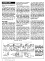
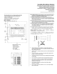
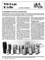
IF amplifiers and their transformers
Superheterodynes have such important advantages over simpler types of receiver that for the past
half century, their use has been practically universal. This month we look at intermediate frequency
or 'IF' amplifiers, the key to the successful performance of any superhet.
The `supersonic heterodyne' receiver,
to give it its full name, had its origins in
World War 1. There is evidence to show
that the French pioneered the superheterodyne concept, but Major Edwin Armstrong of the American Army Signal
Corps is generally credited with creating
the first working examples, and his work
for General Electric enabled RCA to
market the first domestic models.
Initially, the problem that led to the
invention of the superhet was that of obtaining any useful amplification at frequencies around 1MHz and higher with
the triode valves that were then available. The solution embodied in the
superhet was to use the principle of
`beating', whereby the received signal
was combined with a continuous locallygenerated signal, to create a third lower
frequency beat or heterodyne. (Musicians have, of course, for centuries
known about the production of a third
note from two others by aural beating.)
This new signal of much lower frequency (although still above the audio
range
i.e., supersonic) could then be
amplified and detected by conventional
methods, and Armstrong originally used
a resistance-coupled amplifier. Known
as the intermediate frequency amplifier,
and soon shortened to 'the IF', this section of a receiver has a major influence
on receiver performance.
Initially, the purpose of the IF amplifier was simply to provide gain, and resistance-capacity or untuned transformer
coupling was adequate. But by the late
1920's it was realised that tuned circuits
would confer considerable advantages in
terms of higher gain and controlled selectivity.
Depending on their size and complexity, domestic valve receivers had one and
sometimes two stages of IF amplification, coupled by coupled tuned circuits
known universally as 'IF transformers'.
With rare exceptions, these were contained in individual shield cans, with a
remarkable range of styles, shapes and
sizes
round, square and rectangular,
with the older types usually having the
largest cans (Fig.1).
A major advance in size reduction and
efficiency was made in the late 1930's,
with the introduction of powdered iron
cores for the windings. More recently,
ferrite cores have become universal.
Bandpass tuning
Although variations will be found,
general practice was to use two tuned
circuits for each transformer. A pair of
tuned circuits in close proximity and resonant at the same frequency display
some very special characteristics. With
the windings well spaced, only signals in
a narrow range of frequencies will be
passed between windings and severe
sideband reduction occurs, limiting
audio bandwidth in receivers using normal intermediate frequencies. The
bandwidth and signal transfer increases
as the windings are brought closer together, until at the spacing called the
`critical coupling' point, the response
curve is more broadly peaked, and energy transfer is at a maximum.
Critical coupling is frequently used in
IF transformers, as it gives a good compromise between selectivity and reason-
Fig. 1: Valve IF transformers came in many shapes and sizes, and many manufacturers had their own distinctive patterns.
In this group from the author's junk box, there are cans made from aluminium, copper and zinc.
92
ELECTRONICS Australia, June 1993
Fig.3: IF transformer contents varied as much as their cans. The example at far left has a single tuned winding closely
coupled to an untuned secondary; the rest all have two separate tuned windings, with either trimmers or slugs.
There is really no standard frequency
for IF amplifiers. The first untuned transformers favoured frequencies of around
50kHz, but by 1930, 175kHz tuned IF
transformers had become popular and
were used to a certain extent throughout
the decade. This frequency provided stable high gain and plenty of selectivity,
and may well have become the industry
standard frequency. But within a couple
of years, shortwave listening had become popular, and for multiband receiv-
ers, 175kHz was found to be too low for
receiver RF circuits to separate fundamental signals from their heterodyning
images or `second spots'. Consequently
shortwave stations appeared on two
places on the dial.
To minimise 'this problem, intermediate frequencies were raised, generally to
the region of 450 - 475kHz, as high as
was possible without encroaching on the
broadcast band. These frequencies are
still used.
'All wave' European and English receivers had a problem, because of
Europe's longwave broadcasting band
on 150 - 300kHz. To simplify tracking,
many had an IF of only 110 - 125kHz
and there was a serious image problem in
these radios. Even standard broadcast
band images are a potential problem with
IF systems operating below about
250kHz, and in these cases two RF tuned
circuits will frequently be found ahead of
Fig.2: The effect of coil spacing on the
frequencies transferred by coupled
tuned circuits, as in an IF transformer.
A is optimum or critical coupling, C
shows under- and B over-coupling.
Fig.4: Both are tuned to the same
frequency, but the IFT on the left's cores
are in the incorrect `inner' position.
able quality. If however, coupling is further increased, an unusual situation occurs. A peak appears symmetrically
either side of the centre frequency and as
coupling is further increased these peaks
shift further apart (Fig.2). This characteristic is used to good effect in broadening
the IF response in 'high fidelity' or
wideband receivers.
No standard. IF
the frequency converter. It is therefore
usual for a receiver with 175kHz IF amplification to have a three-gang tuning
capacitor, regardless of whether or not
there is an RF amplifier stage.
Despite some efforts at standardisation, there was no consistency in the
choice of intermediate frequency. A
quick check through the Australian Official Radio Service Manual for 1938
shows no less than 15 different frequencies, ranging from 175kHz to 470kHz, in
use for that year's models! Most were in
the range 446 to 470kHz, with
Stromberg-Carlson using the very odd
frequency of 392kHz.
As can be seen in Fig.3, many methods
of IF transformer construction have been
used, but windings were invariably in
separate `pies' with higher frequency
transformers wound with stranded wire.
High frequency currents do not travel
uniformly through conductors, but are
concentrated on the surface by 'skin
effect', which reduces the efficiency of
coils. This effect is minimised by the use
of Litzendraht wire, known universally
as `Litz' wire.
Litz wire is a braided cable made up of
strands of fine wire woven so that each
strand passes from the centre to the outside at regular intervals. This forces each
strand to carry its share of the current and
so lowers the RF resistance of the coil.
Early IF transformer windings were
usually mounted on a wooden dowel and
attached to a block of insulating material
containing adjustable trimmer capacitors
of the mica dielectric variety. Later the
dowel was mounted vertically to permit
a reduction in the diameter of the shield
can. Domestic receiver transformers
using variable capacitance tuning invariably used mica dielectric trimmer capacitors, usually mounted in a ceramic or
ELECTRONICS Australia, June 1993
93
have this problem and it was probably a
major reason for their introduction.
VINTAGE RADIO
The easiest method of finding open
windings is a resistance check, a procedure which should be carried out as
routine anyway. Be suspicious of windings that have significantly higher resistances than their companions. This could
indicate that there are broken strands of
Litz wire, resulting from a developing
green corrosion spot. Alternatively, there
may be a bad termination to the winding.
With each fine strand insulated with
enamel, Litz wire is notoriously hard to
solder. Various methods of removing the
enamel have been suggested, but the
most reliable is very fine abrasive paper
used very gently. Unexpectedly, tests
have shown that the effect of a few broken strands is not serious.
Special types
bakelite block. Fixed capacitors were
frequently used to provide additional capacitance.
In the mid 1930's iron dust slug cores
were introduced, to raise efficiency by
reducing the amount of wire needed.
Later the position of the iron cores was
made adjustable for tuning, rather than
using trimmers. These variable-inductance tuned transformer windings always
have a fixed capacitor, generally mica or
ceramic dielectric, with polystyrene
found in some modern transformers.
Another development was to turn the
coils through 90°, so that they were
alongside each other, rather than axially
on a common former. Later still, windings were enclosed in ferrite 'pots'.
Most IF transformers have the conventional pair of windings, but occasionally
other patterns will be encountered.
Sometimes only the primary winding
will be tuned. This type of transformer is
easily recognised by the windings being
much closer together than normal, with
only one adjustment; or there may be
only one winding.
Three-winding IF transformers have
been used occasionally. Although tuned,
the third winding — used to increase selectivity — has no external connections.
More common are transformers used
in some large receivers with variable selectivity, a good example being the 1938
Tasma/Genelex 580. As can be seen from
Fig.5, a few switched turns of the secondary are wound over the primary
winding. When in circuit, coupling between primary and secondary is increased and the tuning broadened.
Some traps
The position of iron cores in transformers wound on a common former is
important. These transformers can be
recognised by their having an adjustment
screw at each end. As can be seen in
Fig.4, there are two positions of each
core, one either side of its winding,
where the inductance and tuning will be
correct, providing four possible combinations of core positions. These positions
can considerably influence the coupling
between primary and secondary, with
significant changes to the bandwidth.
Individual transformers vary, and if at
all possible, the manufacturer's alignment instructions should be obtained and
carefully followed. Transformers with
in-line windings, and which can be
recognised by their adjusting screws
being at the sides of the cases, do not
Puzzling faults
IF tuning capacitors can provide some
puzzling faults. Defective soldering of
the leaves of mica compression capacitors can produce intermittent drops in
level, and rivets can provide unreliable
contacts. Moulded mica capacitors can
have intermittent changes of capacitance
too, creating frustrating faults.
Ceramic capacitors used with slugtuned windings can occasionally change
to a lower value and provide real traps.
The slug appears to go through resonance as it passes through the centre of
the coil, but the overall gain remains low.
This condition can be recognised by
there being only one peak, whereas normally there are two.
Iron cores can become disconnected
from their adjusting screws, and move
inside the former. The symptoms are an
inability to tune the offending winding,
and the gain of the receiver can vary if
the chassis is tipped or up-ended! It pays
Servicing I F's
Electrically, IF amplifiers are basically
simple, and apart from the usual valve,
resistor and capacitor faults, the most
common problem is open circuited or
'green spotted' transformer windings.
Low frequency IF transformers, generally wound with single strand wire, were
very prone to this type of fault.
Open primary windings are easily
found — there is no voltage at the anode
of the associated valve, and the receiver
is very dead. Faulty secondary windings
may have sufficient leakage for the receiver to work after a fashion, but performance will be very substandard.
GENALEX BC 530
RE
MIXER
6U7G
EK2
I.F AMP 2"DET AVC. I"AUDIO. OUTPUT
6V6G
6G8G
6U7G
47
SPEAKER
T
27
cc'e
•
26
d d
•
6
8 32.-r_
II
13
42
'HI
22
*21
cik
6G5
VISUAL TUNING
INDICATOR
23
cd
0
43
8.1
37
TT3it?
0
28
45
3
36
9 itt.i4
00
o LOCAL
DISTANCE SWITCH
SPEAKER
FIELD--
MAINS
'4..
2000.n.
PLOY
INTERMEDIATE FREQUENCY 458 KC.
ELECTRONICS Australia, June 1993
•
•
SPEAKER
PLUG
5Z4G RECTIFIER
94
•
48
3
30
50
11
29
34
411
1I
20
ZS
24
Iff
43
I4
44
II Ili
19
17
411
5007
Fig.5: In the Tasma/
Genelex BC530, variable selectivity was obtained by winding a few
turns of each IF
transformer's secondary over its primary
winding. With the
switch in the upper position, selectivity was
normal; coupling and
bandwidth increased
progressively in the
two lower positions.
to investigate an IF transformer where a
tuning control has no effect.
Fitting replacements
Nothing stands out to the experienced
eye like a `foreign' IF transformer. If an
exact replacement is not available, it is
often possible to insert the internals of
another make into the original can. Fortunately, most transformers will operate
satisfactorily over a range of frequencies
and a unit intended for say 455kHz will
usually operate quite well at any frequency from 450 to 470kHz. Never
throw out a junked chassis without first
salvaging the IF transformers!
When working with IF transformer
windings, it is essential to observe the
sequence of connections. Swapping the
connections of a winding can reduce
gain considerably. Assuming that the
windings are in the same direction, if a
grid or diode lead is connected to the
start of one winding, then the anode will
be connected to the end of the other
winding and vice-versa.
A warning to beginners: IF amplifiers
are normally very stable, so do not attempt re-alignment unless you sure that
the receiver is otherwise working correctly and you are reasonably sure that
settings have been tampered with. Even
after many years of use, most IF adjustments will be found to be correct.
Unfortunately though, as any serviceman will tell you, accessible IF alignment screws seem to hold a fatal
attraction for non-technical people attempting to get a set working. Many
manufacturers sealed adjusting screws
with wax, and in these cases, chances are
that the alignment will not have been
tampered with.
If it really is necessary to realign an IF
amplifier, the maker's instructions
should be obtained if at all possible.
However, in an emergency, and provided
that a signal generator is available and
the set's intermediate frequency is
known, some alignment can be done.
Clip a high resistance digital voltmeter
or a vacuum tube voltmeter to the AGC
line or diode load resistor. Inject a signal
at the set's intermediate frequency into
the control grid of the frequency converter, sufficient to give a reading on the
meter of between 2V and 3V. Now, keeping the injected signal always at a minimum to give a meter reading, peak each
trimmer in succession.
Powdered iron cores are very brittle
and are easy to damage irreparably.
Therefore, never adjust them with a steel
screwdriver, but use a plastic alignment
tool or a piece of sharpened plastic knitting needle or even hardwood. ❖
Collector's Corner
Where readers display prized items of radios and other equipment from
their collections, and/or seek information from other collectors...
ougosseiniklar
Club members make
`Little General' copies
Rodney Champness, who is publicity officer for the North East Vintage Radio Club
(based in Wangaratta, Victoria), tells me
that this year the Club members set themselves the challenge of building replicas of
the `Little General' receiver, first described
by John Moyle in the April 1940 issue of this
magazine. He says that the idea of doing so
came from the articles we ran last year by
both Peter Lankshear and Neville Williams,
telling the story behind the design.
The set judged best was to be awarded
the Club's annual Hellier Award, — named
in honour of Mr Les Heller, who built the
town's radio station 3WR and began broadcasting on the 25th February, 1925 (it was
apparently the first licensed station in any of
Australia's country towns).
Some 16 Club members accepted the
challenge, and set about scrounging parts,
making chassis and building cabinets.
When judging took place, the winning set
was a replica of the 1947 Little General built
by Ralph Robertson, of Kyabram, and pictured both in the front centre of our main
shot above and at lower right. The other
sets in the main shot are (top centre)
Rodney's own version of the 1957 model,
which won second prize; (left) Noel
Meagher's version of the 1961 model; and
(right) Bob Young's replica of the 1947
model. The last two sets tied for third place.
At upper right is a shot of another Little
General built by a Club member, and
housed in a `cathedral' style cabinet. Rodney says that the builder is a skilled woodworker, and the cabinet is `magnificently
finished'.
Rodney says that the. NEVRC caters for
anyone with an interest in early radio, from
technical and restoration work to collection
of magazines and recordings, etc. Further
information is available by writing to him at
17 Helms Court, Benalla 3672, or phone
(057) 62 1454. +
.:::
.....:......................................................
Valve
Electronics
001.1.1.1.1.10.:. 140 .1401 ..:.:.1.s.HM..•«.b:.T
H1•1«.T 1 .0144T. 01.;.z.F...:.1.:.L ;:
Sale Repairs Resurrection
_. and Overhaul of: valve
•
radios — audio gear
•' instrumentation.
12 month warranty on all
work.
ip Parts sales, circuit copies, •
E. custom construction of
valve gear.
•
•
V11FÅtII
WIIRIEiöLöESö,
N
- r
O
z
0
U-z
tr
60 Australia St Camperdown LU
NSW 2050
w
Phone: 557 2212
..oc