1
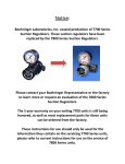
Thoracic Suction Regulator: Model 3750 Boehringer Laboratories, Inc. P.O. Box 870 Norristown, PA 19404 800-642-4945 Covered under one or more of the following patents: 6,264,890 6,228,056 5,992,239 5,879,624 5,409,491 5,372,593 5,354,262 5,203,778 2008 Boehringer Laboratories, Inc. © Drawing 3750.008 Rev. C P/N 33534 3750 User Manual Released November 2008 Page 1 of 14 Contents WELCOME Congratulations on your purchase of a Boehringer Suction Regulator. We consider our Suction Regulators to be the best in the world. We are confident it will provide you with reliable, trouble-free, safe patient care and low cost of operation. This product is intended for use by individuals properly trained in suctioning procedures by or on the order of a physician. Please read these instructions carefully. Declaration of Conformity ......................................................................................................... 2 Definition of Terms/ Symbology ............................................................................................... 4 Safety Information .................................................................................................................... 5 Operation .................................................................................................................................. 6 Features ................................................................................................................................... 6 Installation ................................................................................................................................ 7 Common Fittings and Adapters ................................................................................................ 7 Mode Selection ......................................................................................................................... 8 Test........................................................................................................................................... 8 Clinical Use............................................................................................................................... 9 Maintenance ............................................................................................................................. 9 Cleaning & Disinfection ............................................................................................................ 9 Disassembly ............................................................................................................................. 10 Assembly .................................................................................................................................. 10 Troubleshooting ........................................................................................................................ 11 Specifications ........................................................................................................................... 12 Warranty and Repair ................................................................................................................ 12 Exploded View .......................................................................................................................... 13 Parts ......................................................................................................................................... 13 Drawing 3750.008 Rev. C P/N 33534 3750 User Manual Released November 2008 Page 2 of 14 0123 Definition of Terms and Symbology CE Mark: notified body for the European Union VACUUM Air or other gases sub atmospheric pressure typically expressed as mm Hg or cm H20 SUCTION A use of vacuum that causes a fluid or solid to be drawn into an interior space or to adhere to a surface because of the difference between the external and internal pressures Alerts the user to the presence important operating and maintenance instructions in the literature accompanying the device WARNING Alerts user to actions or conditions that could result in injury to user or patient CAUTION Alerts user to actions or conditions that can cause damage to the device or may result in substandard performance of the device or system. IMPORTANT Indicates an action that is emphasized to ensure proper operation of equipment OFF Supply suction is off and patient circuit is vented to atmospheric pressure REG Supply suction is on and regulated output is controlled to prescribed setting DROOP: Accuracy of regulation depends primarily on the ability to provide a consistent level of vacuum under changing flow conditions. Involuntary pneumatic biopsy, or tissue damage, can occur when high levels of vacuum are applied to delicate tissue. With a Boehringer regulator, you can depend on very low “droop” compared to our competitor’s models. Boehringer regulators are checked 100% on the assembly line to meet a specification of less than 10mm Hg droop at a 100mm Hg setting. “Droop” is the variation in the vacuum as flow changes from a flowing condition to an occluded condition. We measure droop as the change in vacuum measured from full flow to dead-ended on a typical collection circuit with a 14 French catheter. An evaluation of a regulator’s droop allows one to determine whether the device is truly “regulating”. A safe and reliable regulator should regulate to its set position regardless of variable flow conditions. PARALLAX Inaccuracy caused by observational position of an indicating element (pointer) to a reference element (scale). Drawing 3750.008 Rev. C P/N 33534 3750 User Manual Released November 2008 Page 3 of 14 Safety Information WARNING! This product is intended for use by or on the order of a physician. It is to be used by individuals who are properly trained in medical suctioning procedures. Please read these instructions carefully. Suction regulators must only be attached to vacuum systems. compressed air, nitrogen, or oxygen sources. Suction catheters, collection canisters and suction tubing must be carefully evaluated and selected to ensure adequate function for the specific clinical environment and intended field of use. Do not use Boehringer suction regulators in the presence of flammable anesthetics. Do not attach to There have been reports of increased intracranial pressures associated with endotracheal suctioning procedures. "Persistent, increased ICP has been associated with neurological damage and fatalities". (Health Care Product Comparison Systems, Regulators, Suction, ECRI Plymouth Meeting, PA Oct'97). Always verify regulator operation (Droop, see page 4 for details) before use on a patient. Verify operation by establishing the desired vacuum level with the collection circuit and suction catheter attached to the regulator. Occlude the suction catheter and note that the indicated vacuum does not rise by more than 10% of the original setting. Thoracic Regulator: Thoracic Regulators are intended for use with chest drainage devices such as the Pleur-evac (Deknatel) that employ high pressure relief devices for relief of high intra-pleural pressures as may be encountered during a coughing episode. CAUTION! Collection canisters are mandatory for all suction procedures. We strongly recommend the use of an overflow protection device (filter or trap bottle) at all times between the regulator and collection canister. See Accessories at the end of this manual. Drawing 3750.008 Rev. C P/N 33534 3750 User Manual Released November 2008 Page 4 of 14 Operation FEATURES Patented Linear Gauge: Eliminates PARALLAX Allows accurate readings from 180° field of view and never requires calibration. Each range has unique color-coding DECREASE Mode Selector Valve: Square knob to easily switch between operating modes. OFF and REGULATE Adjusting Knob: Extra large, easy grip knob turns COUNTER-CLOCKWISE (direction of arrow) to increase suction setting and CLOCKWISE to decrease suction setting INCREASE WARNING!- Safety Port: Do not occlude Safety Module: 1. High Negativity Safety Vent: Safety mechanism limits maximum suction to 60cm H2O. 2. Positive Pressure Relief: Safety mechanism vents excess positive pressure WARNING! Do not remove Safety Module or use Thoracic Regulator without the Safety Module. Drawing 3750.008 Rev. C P/N 33534 3750 User Manual Released November 2008 Page 5 of 14 INSTALLATION All Boehringer suction regulators are supplied with 1/8” NPT female ports. The standard port facilitates simple adaptation to any quick disconnect system. Fittings are available from Boehringer to adapt to your quick connect system. We recommend you purchase the appropriate fittings with your regulator at the time of purchase. The fittings will then be factory installed prior to shipping. By purchasing the regulator and fittings (a complete system) simultaneously, the factory will apply the unmatched 10 Year Warranty of our suction regulators to the fittings as well. See page 13 for complete warranty details. In the event that you must assemble or disassemble fittings, please follow these instructions: 1. Assemble desired male quick connect to the wall adapter port on the back of the regulator using teflon tape. 2. The patient connection fitting must be supplied by Boehringer Laboratories to insure optimal performance. WARNING! Only approved CGA DISS adapters may be used with trap bottle or canister configuration. 3. The regulator is now ready to be placed in service on your suction system. Wall Adapter Port (rear) Patient Connection Port (bottom) Location Patient Connection Port Configuration CAUTION! Use of a protective device in the collection circuit such as a safety trap bottle is recommended. The trap can protect suction equipment and piping components from inadvertent infiltration of fluids. Order Number and Description Model 2469 Suction tubing attached directly to the suction regulator High Flow Bubble Barb Suction regulator attached to collection canister, roll stand or trap bottle DISS Body Adapter Model 1487 Model 1492 Vacuum outlet requires a 90° twist to release the regulator Diamond Ohio Model 1493 Wall Adapter Port Vacuum outlet has a button to release the regulator Chemetron (NCG) Rectangular Adapter Model 1504 The adapter screws onto the outlet and then is unscrewed to remove (approximately 3 turns) Drawing 3750.008 Rev. C P/N 33534 3750 User Manual Released November 2008 DISS Hand-Tight Nut and Gland Page 6 of 14 MODE SELECTION Selector Valve: Two-way control valve with OFF and REG, modes but not LINE. TEST 1. With the control valve in the REG position and a collection system attached with a 14 Fr. catheter, regulator must control vacuum from 10-100% of full scale. 60 cm H2O 2. With the control valve in the REG position and housing turned all the way off, with suction port occluded, gauge must read zero. 3. With the control valve in the REG, adjust regulator to the middle of the scale and occlude the catheter. Gauge movement must be less than 5% of the full scale of the regulator. This measurement is called droop. 4. The gauge is accurate to ±5% of full scale for any measurement within the range of the scale. If this is not the case, please return the gauge to the manufacturer for repair/replacement. CAUTION! Inaccurate gauge calibration may lead to a high suction condition applied to the patient. 5. With the control valve in the OFF position, suction must be at atmospheric and gauge should read zero. With suction port occluded, gauge must read zero. 6. With the control valve in the REG position, set the Regulator to the middle of the scale and turn control valve to OFF, then back to REG. Gauge indicator must not travel more than 20% past the set point before settling at the desired level. 7. Verify that the relief valve is functional as evidenced by a noticeable flow at the inlet of the safety port (see diagram page 6) when the regulator is set to maximum suction. Be sure that the lock screw (refer to step 17, Assembly and Lubrication, pg 11) is engaged and limiting the outward travel of the housing assembly. 8. A final, important step in instrument maintenance is the identification of the instrument. This confirms that a qualified individual performed service to approved procedures and master gauges. An ID tag should accompany the instrument, which indicates (as a minimum): date of service, individual performing the service and the date of next service. CAUTION! Have the regulator factory serviced if not performing to specifications. See Warranty and Repair on p. 12 for details on getting your instrument factory serviced. Drawing 3750.008 Rev. C P/N 33534 3750 User Manual Released November 2008 Page 7 of 14 CLINICAL USE Attach Model 3750 Thoracic Suction Regulator to the suction port on the chest drainage device with an underwater seal to be utilized. Follow manufacturer’s instructions regarding proper set up and use of the chest drainage device. The drainage device must incorporate an underwater seal. Adjust Model 3750 Suction Regulator to desired level. Consult chest drainage device instructions for recommended suction level. The Safety Vent will emit a noticeable venting sound when the regulator is set above 55 mmHg. WARNING! For use only with disposable chest drainage devices equipped with an underwater seal and overpressure protection MAINTENANCE Boehringer Regulators have been designed to function for at least ten years of trouble-free service with minimal care. To determine the maintenance schedule your medical facility should follow, we recommend the following: • Periodically (as required, but no less than annually) inspect the overall condition of the instrument. Test the gauge accuracy and check the instrument function as described under Instrument Test. • Based on data from your periodic inspections, determine a cleaning schedule. Clean, inspect, lubricate, and test based on your schedule and according to the Instrument Cleaning and Disinfection, Instrument Lubrication and Instrument Test sections outlined below. CLEANING & DISINFECTION Cleaning: The most significant cause of regulator failure is the lack of a comprehensive cleaning and maintenance program. • At any time, the assembled regulator may be rinsed by drawing a 5% Liqui-Nox®/water solution through it. After flushing, aspirate air through the regulator for 1 minute, or until dry. • In the event suctioned material should enter the regulator, or a scheduled cleaning is required, follow the appropriate Disassembly procedures (see page 10). 1. Regulators should be thoroughly disassembled and cleaned prior to any disinfection cycle. 2. All regulator parts may be soaked in a solution of warm water and lab ware detergent (such as Liqui-Nox®) and scrubbed using a soft brush if necessary to remove proteinaceous deposits. Disinfection: It is the responsibility of the Medical facility to perform the steps outlined in this procedure and to determine that the recommended cycles are providing an effective level of disinfection for the particular device in use. IMPORTANT! After cleaning, any of the following procedures are acceptable modes of disinfection for all parts of the regulator, but not necessarily wall fittings. When disinfecting, be sure the device is disassembled and the wall fittings are not included. Drawing 3750.008 Rev. C P/N 33534 3750 User Manual Released November 2008 Page 8 of 14 • • • • EtO Cidex® Sterrad® (Cidex® and Sterrad® are registered trademarks of Johnson & Johnson) Autoclave Reference Boehringer Labs Disinfection Procedure 4100.018 for more detail. DISASSEMBLY (See Fig. 1) Regulator: 1. Back out lock screw (8) on housing assembly (7) with 1/16 hex wrench. 2. Unscrew diaphragm housing (7) from regulator body (12). 3. Remove valve retaining screw (9) and washer (10) with 5/32 hex wrench. Pull out control valve (15). 4. In the unlikely event suctioned material should enter the regulator diaphragm housing, it will be necessary to disassemble and scrub the unit as follows: a. Remove lens cap retaining ring (1) and lens cap (2). b. Push out diaphragm (3) by pressing on piston/stem assembly (4). c. Remove piston/stem assembly (4) and spring (6). Gauge: 5. Remove the retaining ring (18) using retaining ring pliers. From the front of the gauge, use thumb to rotate and loosen view tube (19). Then remove view tube-pistondiaphragm assembly (19-20-21). 6. Remove the retaining ring (17) using retaining ring pliers. 7. From the front of the gauge, use thumb to rotate and loosen view tube (19). Then remove view tube-piston-diaphragm assembly (19-20-21). 8. Remove the lower lip of the diaphragm from outside of the view tube, and slide out the diaphragm-piston assembly. 9. Remove the upper diaphragm lip from the top of piston, and slide diaphragm off piston. 10. Remove spring (22). NOTE: It is not necessary to remove the gauge body (24) from the regulator body (12) prior to cleaning. Relief Assembly: 11. Remove retaining ring (1), Lens cap (25) and diaphragm (3) from body (32). Remove piston (26) and spring (27). Test for free movement of poppet (29) IMPORTANT! Always clean the unit prior to assembly. See the Cleaning and Disinfection pg 9 for details. Drawing 3750.008 Rev. C P/N 33534 3750 User Manual Released November 2008 Page 9 of 14 ASSEMBLY AND LUBRICATION (See Fig. 1) After disassembling and cleaning the instrument, assemble and lubricate as follows. Parts are available from Boehringer Labs and may be ordered by part number (P/N). Part numbers are found in figure 1 at the end of this manual. Regulator: 1. 2. 3. 4. 5. 6. 7. 8. 9. Lubricate control valve (15) over entire mating surface with synthetic lubricant (P/N 1895). Rotate valve as you insert it into the body. Remove the valve and inspect for dry areas. The valve must have a thin layer of lubricant over its entire diameter without excess in the cross ports. Insert the control valve (15), and position the valve retaining washer (10) before securing it with the valve retaining screw (9) Lubricate the threaded sleeve in diaphragm housing (7) and U-cup (11) with a light coat of synthetic lubricant (P/N 1895). Inspect seal on the end of the piston stem assembly for cuts or wear. Replace entire piston stem assembly if needed. Place spring (6) on piston/stem assembly (4) and then insert through diaphragm housing assembly (7). Cover piston/stem assembly (4) with diaphragm (3) and lens cover (2) and snap lens cap retaining ring (1) into groove. Assemble housing (7), then screw housing into body (12). Tighten lock screw (8) to retain diaphragm housing on regulator body groove. Back off ½ turn only. Gauge: 10. Slide large end of diaphragm (20) over piston (21) until top ring snaps into groove in piston. Be certain the top bead of the diaphragm is completely engaged into the groove of the piston. CAUTION! If the diaphragm is not seated properly it will rub against the view tube and may lead to premature failure of the gauge. 11. 12. Slide view tube over diaphragm-piston assembly. Roll edge of diaphragm around bottom of view tube and into groove. Make sure there are no folds or twists and that diaphragm is smooth. 13. Insert spring (22) into piston/view tube subassembly. 14. Slide piston subassembly with spring up (gauge body facing down) into gauge body (24). 15. Press until view tube assembly rests on shoulder in gauge body. 16. Assemble retaining ring (18) into groove in gauge body. Regulator: Relief Assembly: 19. Reassemble spring (27), Piston (26), diaphragm (3) and lens cap (25) and replace retaining ring (1). WARNING! Failure to perform Step 8 may expose patient to high vacuum IMPORTANT: Always test the reassembled unit after each maintenance procedure. See the Test section page 8 for exact test procedure. Drawing 3750.008 Rev. C P/N 33534 3750 User Manual Released November 2008 Page 10 of 14 TROUBLESHOOTING Boehringer Suction Regulators have been designed for years of trouble-free service. Should you experience difficulty that is not the result of damage to the instrument, the most likely cause is aspiration of dirt and/or fluids into the Regulator. Symptom Probable Cause Solution Instrument fails to provide suction at the patient port. The supply or patient fittings are clogged Replace or clean the fittings Gauge doesn't respond to changes in suction (via control valve or adjustment knob) Gauge diaphragm is improperly sealed on the gauge piston and/or view tube Disassemble gauge and check the position of the gauge diaphragm. Gauge piston is discolored Material has entered the inside of the gauge Instrument is contaminated. Disassemble and clean the instrument. Gauge responds slowly to changes in suction The small hole in the top of the View Tube may be plugged. Using a small diameter probe, pierce the hole to clear the obstruction. Instrument will not shut off or exhibits high droop Dried fluids may have cut the quad ring seal. Replace the quad ring (5) and Test the unit as per above procedure. Instrument fails to regulate suction Piston/Stem surface is binding with foreign matter Disassemble and clean the instrument. Erratic gauge movement resulting from regulator adjustment Gauge is not sealed Make sure retaining ring (17) is seated in groove on the gauge body and there is no end play in the view tube (19). IMPORTANT! Always test the reassembled unit after each maintenance procedure. See the Test section, page 8, for exact test procedure. SPECIFICATIONS • • • • • • Inlet and outlet fittings: 1/8 NPT Gauge accuracy ±5% FSO Regulation Accuracy: ±10% F.S. from full flow to zero flow with 14 FR catheter attached. Leak rate in OFF position: less than 1 cc/min Free Air Flow (Model 3750): Greater than 20 LPM with regulator set to 60 cm H2O at standard JCAHO supply (305mmHg @ 180 SCFH). Materials: polycarbonate, hard-anodized aluminum, stainless steel, Buna rubber, silicone, acetal copolymer. Model Regulation Range User Selectable Modes 3750 6-60 cm H2O Off, Regulated Control Wt. (lb)* 2.0 *Regulator weights are without fittings. Operating and Storage Limits We recommend that Boehringer Suction regulators be operated and stored at controlled conditions that typically reflect a medical facility environment. Drawing 3750.008 Rev. C P/N 33534 3750 User Manual Released November 2008 Page 11 of 14 H x W x D (in) 9 x 21/2 x 4 WARRANTY AND REPAIR Boehringer Laboratories, LLC guarantees all 3700 Series LONG LIFE Suction Regulators for TEN years. The 7700 Series Suction Regulators have a FIVE year warranty with the exception of the gauge which has a one year warranty. Boehringer Laboratories, LLC will also warrant all fittings purchased from and installed by Boehringer Laboratories, LLC for the same warranty period as the suction regulator on which they were originally installed. Boehringer Laboratories, LLC warrants to the original purchaser, new suction regulators purchased directly from Boehringer Laboratories, LLC or from an authorized dealer or representative. This warranty guarantees the suction regulators to be free from functional defects in materials and workmanship. We also guarantee that our suction regulators will meet our published specifications. All regulators returned for repair shall be clean and free from contamination prior to shipment to Boehringer Laboratories. This requirement is for the safety of our employees as well as to comply with Federal Law prohibiting the shipment of unmarked biohazard materials. If units are returned contaminated, a cleaning charge may result. A service charge may be assessed on any unit returned that shows evidence of gross abuse. Boehringer Laboratories, LLC is the only authorized warranty service center for our suction regulators. Any repair service requesting a return authorization for repair will be asked to provide the name and location of the original equipment purchaser. If this information cannot be provided, the repair is not covered under warranty and will be a chargeable repair. This warranty excludes acts of God, fire, flood and acts of war, terror or insurrection. This warranty is not transferable from the original purchaser. Boehringer Laboratories’ sole and exclusive remedy under this warranty is limited to repairing and/or replacing the suction regulator. There are no other express or implied warranties beyond these warranties set forth above. At Boehringer Laboratories, we are committed to lowering your suction regulator costs of operation! All repairs will be shipped back within five days of receipt of purchase order authorization. For quality factory service, call 800-642-4945 or 610-278-0900 for your return authorization. Ship returns to: Boehringer Laboratories, LLC Repair Department 500 E. Washington Street Norristown, PA 19401 New Products We are continually striving to reach higher and higher standards of quality. We value your comments and input on our suction regulators. If you are pleased with this instrument, please find out more about Boehringer Laboratories' complete line of suction controls. Drawing 3750.008 Rev. C P/N 33534 3750 User Manual Released November 2008 Page 12 of 14 Figure 1 No. P/N 1 2 3 4 5 6 7 8 9 10 11 12 13 14 15 16 17 1465BK 33528 1466 33537 1461 33525 1871 1479 1468 1454 1484 1458HC 1462 1480 32981HC 353 33055 Description No. P/N Lens Cap Retaining Ring Lens Cap, Model 3750 Regulating Diaphragm Piston Stem Assembly Quad Ring Spring 0-60 cm H2O Diaphragm Housing Assembly Lock Screw Control Valve Retaining Screw Control Valve Retaining Washer U-Cup Regulator Body1 Thumb Spring Thumb Spring Retaining Screw Control Valve Control Valve O-Ring CE Label 18 19 20 21 22 23 24 25 26 26 27 28 29 30 31 32 33409 33040 33042 33539 33526 33043 33532 32963 2342 32962 33531 2147 32997 32965 32961AN 32960AN Description Gauge Retaining Ring Gauge View Tube Gauge Diaphragm Gauge Piston Gauge Spring 0-60 cm H2O Fastener Gauge Body with Label (0-60 cm H2O) Lens Cap Silicone Sheet Piston Relief Spring, Thoracic ⅛” Hex Nipple Poppet Tuning Spring, Thoracic Adjusting Cap Body 1. The Spool, Control Valve, and Reg. Body are factory matched. Please call for details on replacement. Drawing 3750.008 Rev. C P/N 33534 3750 User Manual Released November 2008 Page 13 of 14 Boehringer Laboratories, LLC 500 E. Washington Street Norristown, PA USA 19401 For Customer Service Or Technical Support 800-642-4945 www.boehringerlabs.com A free trial evaluation of any of our suction regulators can be arranged by calling (800) 642-4945 or 610-278-0900. Drawing 3750.008 Rev. C P/N 33534 3750 User Manual Released November 2008 Page 14 of 14