1
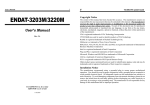
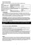
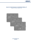
BTM44X – Firmware Upgrade
Application Note
v1.0
Introduction
The BTM44x Enhanced Data module has a feature set, in firmware, which is continually evolving.
At any time the module has a specific production release of the firmware. At the same time on application,
newer engineering builds of the firmware can be made available. These are released to fix issues that have
been discovered since the production release or have new profiles and features.
The module is available so that one of two interfacing protocols can be activated over the UART port. One is
the multipoint packet protocol (MP) mode and the other is the AT protocol.
In AT mode, the firmware version information is sent in response to the ATi3 command.
In MP mode, the firmware version information is sent in response to the CMD_INFORMATION[0] command.
Upgrading firmware over the UART consists of temporarily changing the protocol to one which is used by the
boot loader, is packet based and is specific to the upgrade process, called BCSP mode. It is not documented
in the user manual given that it is only used for upgrades and that process is managed via PC-based utilities,
so it is normally transparent to a host. The only time this protocol is exposed to the host is when an upgrade
is interrupted and the module has incomplete firmware. In that case, the boot loader detects corrupt
firmware and remains in boot mode, exposing BCSP mode to allow further attempts at firmware downloads.
It is also possible to upgrade the firmware over a SPI bus interface which is exposed via four dedicated pins
on the module labelled as SPI_CSB, SPI_MISO, SPI_MOSI and SP_CLK. See the user manual for full pinout.
Upgrading firmware over the air is not planned as it is not inherently supported by the chipset vendor.
New firmware is deployed in files with extension .dfu, which are self-contained with all the necessary
information to expedite a firmware upgrade.
This document describes measures a designer can take to make the process of upgrading the firmware easier
based on understanding the various options.
Upgrading firmware on a Development Kit
The BTM44x module on a dev kit has its UART exposed directly to a Windows PC via a USB virtual COM port.
In this case the process of upgrading the firmware is as simple as launching a utility called Btm44xConfig.exe
in interactive mode and pointing it to the new firmware file (with a .dfu extension).
The main window for the firmware upgrade utility is as per the snapshot below.
Americas: +1-800-492-2320 Option 3
Europe: +44-1628-858-940
Hong Kong: +852 2923 0610
www.lairdtech.com/wireless
1
Laird Technologies
BTM44X – Firmware Upgrade
Application Note
Change the COM port as per the setting in the PC for the dev kit, specify the protocol and COM port
parameters for ‘Start With’ and ‘Exit With’, select the filename in the appropriate text box (which may be
automatically selected if there is only one .dfu file in the same folder as the utility) and then click Upgrade.
The whole process takes up to 5 minutes. On successful upgrade the module will be left in the state specified
by the parameters labelled as ‘Exit With’
If the upgrade process was previously aborted, i.e. via a power interruption, the module starts in BCSP boot
loader mode. The utility is designed to detect for that state if the ‘Start With’ parameters do not yield a
response from the module. It will check for BCSP mode and if that results in a positive detection it will
download the new firmware. It may try to exit with the parameters specified in ‘Exit With’. That final phase
may fail. If so, manually try to detect the module by trying MP and AT modes at 115200 and 9600 baud.
The firmware upgrade utility can operate in automatic mode by supplying relevant parameters as command
line arguments. For example, if the kit is on COM34, the new firmware file is called NewFirmware.dfu and
the module is in AT mode but must exit in MP mode, then the command line arguments will be
COM=34 "DFU=NewFirmware.dfu" PROTs=AT BAUDs=115200 PARs=NONE STOPs=1 PROTe=MP
BAUDe=115200 PARe=NONE STOPe=1 UPGRADE
If the utility is launched with these arguments, it starts and exits on completion without further intervention.
If the upgrade process fails, a log file (which is always) offers full trace information to diagnose the failure.
Upgrading firmware on Host Hardware
In real world applications the UART interface of the BTM44x module will be most likely directly connected to
the UART port of a host CPU which is managing the module and the UART signals of the module are not
exposed to allow a Windows PC to use the Btm44xConfig utility to upgrade the firmware. In this scenario it is
not possible to upgrade the firmware.
However, it is possible to augment the host/module hardware design to expedite a firmware upgrade.
There are several options available and they are described in subsequent sections of this document.
Americas: +1-800-492-2320 Option 3
Europe: +44-1628-858-940
Hong Kong: +852 2923 0610
www.lairdtech.com/wireless
2
Laird Technologies
BTM44X – Firmware Upgrade
Application Note
Option 1: Multiplex the UART lines
This upgrade option requires direct connection to RX, TX, CTS and RTS lines of the module, via appropriate
RS232 level conversion, to a serial port on a Windows PC.
In that case, 2 of the 4 UART lines of the module cannot be directly exposed because the RX and CTS input
lines will be driven by the host microcontroller and hence cannot also be driven by a Windows PC.
One solution would be to incorporate the hardware logic illustrated below and use a USB to Serial adapter as
described at the website http://www.ftdichip.com/Products/Cables/USBTTLSerial.htm This has the further
advantage of not requiring RS232 level conversion.
In this arrangement the extra cost to the bill of materials consists of components that implement the
multiplexing of the RX and CTS lines. This multiplexing can be via a header/jumper arrangement or it can be
logic gates driven by the Vcc line of the 6 way USB F/W Conn that allows the USB to Serial adapter to gain
control of the BT module.
With this arrangement, while the external PC is interacting with the BT module, any outgoing comms traffic
will also reach the host microcontroller. This does not detrimentally affect the operation of the controller. If
this could be an issue, we advise you also multiplex the TX line from the modules. The host controller may
also sense the Vcc line from the F/W Conn to provide logic to ignore UART traffic when it is asserted.
Option 2: Bridge UART traffic
This upgrade option requires that the host controller has permanent connections to the UART port of the BT
module AND has some other means of communicating with the outside world (a TCP/IP connection or a
second UART port exposed so that a Windows PC has direct connection).
Americas: +1-800-492-2320 Option 3
Europe: +44-1628-858-940
Hong Kong: +852 2923 0610
www.lairdtech.com/wireless
3
Laird Technologies
BTM44X – Firmware Upgrade
Application Note
If a TCP/IP connection is the other means of connection, you will need a windows PC with TCP/IP to virtual
COM port bridge software (an example: http://www.tacticalsoftware.com/products/serialip/index.htm). This
TCP/IP to Serial port bridge is required to use Btm44xConfig.exe.
The host microcontroller which controls the bridge for the UART traffic must have firmware functionality to
prepare the BT module for a firmware upgrade. When triggered, the firmware must revert the module to
BCSP boot loader mode and then bridge all bidirectional traffic between the BT module and the Windows
PC.
When the host controller is triggered, it shall perform the following actions, where <cr> implies the carriage
return character 0x0D and <del> is the backspace character 0x08.
1.
2.
3.
4.
5.
6.
7.
8.
9.
10.
11.
12.
13.
14.
15.
16.
17.
18.
19.
20.
21.
22.
23.
24.
25.
26.
27.
28.
29.
30.
31.
32.
33.
If the BT module is in MP mode, go to step 9.
Send command ATS520? and store the returned value for later use.
Send command ATS520=115200<cr>
Send command ATS522? and store the returned value for later use.
Send command ATS522=1<cr>
Send command ATS523? and store the returned value for later use.
Send command ATS523=0<cr>
Advance to step 16.
Read content of S register 240 and store for later use using command CMD_READ_SREG.
Write 115200 to S register 240 (0xF0) using the MP command CMD_WRITE_SREG.
Read content of S register 242 and store for later use using command CMD_READ_SREG.
Write 1 to S register 242 (0xF2) using the MP command CMD_WRITE_SREG.
Read content of S register 243 and store for later use using command CMD_READ_SREG.
Write 0 to S register 243 (0xF3) using the MP command CMD_WRITE_SREG.
Write 2 to S register 255 (0xFF) using the MP command CMD_WRITE_SREG.
Send command CMD_RESET. The module wakes in AT mode at 115200,N,8,1
Configure the host microcontroller UART for 115200,N,8,1 operation and AT protocol.
Send command ATS32767=? <cr> and store the returned decimal value (in the range 0 to 255).
Send command ATS32767=n<cr> where n is the decimal value returned in step 12.
Send command AT+BT!<del>!<cr> where <del> is the 0x08 ASCII character.
The module is in BCSP mode and sends BCSP sync packets at 115200,N,8,1. The host can verify
this by looking for at least one 5 byte sequence C0 01 0B 09 90.
Activate the bridge. From here on, all traffic is bridged across bidirectionally.
Launch the firmware upgrade utility on the Windows PC.
While the bridge is active, restart a 40 second timer as long as there is data traffic from the PC
towards the BT module
If the timer expires, this signals that the firmware upgrade is complete. Disable the bridge.
Reset the BT module by either toggling the hardware RESET line of the module, or by sending a
BREAK for about 500 milliseconds.
The BT module wakes in AT Mode at 115200,N,8,1.
Write to S Reg 520 the value returned in either step 2 or 9.
Write to S Reg 522 the value returned in either step 4 or 11.
Write to S Reg 523 the value returned in either step 6 or 13.
If the module was in MP mode at step 1, send command ATS9255=1.
Reset the BT module by either toggling the hardware RESET line of the module, or by sending a
BREAK for about 500 milliseconds.
The module is now in the same mode and state as at step 1, but with new firmware installed.
Americas: +1-800-492-2320 Option 3
Europe: +44-1628-858-940
Hong Kong: +852 2923 0610
www.lairdtech.com/wireless
4
Laird Technologies
BTM44X – Firmware Upgrade
Application Note
Option 3: Upgrade via SPI bus
This option requires that the five pins on the BT module be exposed via appropriate means so that a
Windows PC connected by USB to SPI bus adapter may run a utility and upgrade the firmware. This is NOT
Btm44xConfig.exe, used previously.
Instead, the firmware upgrade file consists of a pair of files, one with a .xdv extension and the other with
.xpv. These files are not made generally available, but will be available to customers, on application, who are
willing to sign an NDA with Laird so that a third party utility can be made available.
The USB to SPI bus adapter can be purchased online (e.g. http://parts.digikey.com/1/parts/1406287converter-usb-spi-devsys-1808-1a.html). The five pins to make available for external connection to the USB to
SPI adapter are:
GND
SPI_CSB
SPI_MISO
SPI_MOSI
SPI_CLK
Pin
Pin
Pin
Pin
Pin
7
8
9
10
11
The USB to SPI bus adapter documentation describes the RJ45 socket pinout, enabling an appropriate cable
to be made up from an existing network patch cable.
REVISION HISTORY
Revision
Date
1.0
24 Nov 2011
Description
Initiated By
Initial Release
Jonathan Kaye
Copyright © 2013 Laird Technologies, Inc. All rights reserved.
The information contained in this manual and the accompanying software programs are copyrighted and all rights are reserved by Laird Technologies, Inc. Laird
Technologies, Inc. reserves the right to make periodic modifications of this product without obligation to notify any person or entity of such revision. Copying,
duplicating, selling, or otherwise distributing any part of this product or accompanying documentation/software without the prior consent of an authorized
representative of Laird Technologies, Inc. is strictly prohibited.
All brands and product names in this publication are registered trademarks or trademarks of their respective holders.
Information furnished by Laird Technologies in this specification is believed to be accurate. Devices sold by Laird Technologies are covered by the warranty and
patent indemnification provisions appearing in its Terms of Sale only. Laird Technologies makes no warranty, express, statutory, and implied or by description,
regarding the information set forth herein. Laird Technologies reserves the right to change specifications at any time and without notice. Laird Technologies’
products are intended for use in normal commercial and industrial applications. Applications requiring unusual environmental requirements such as military,
medical life-support or life-sustaining equipment are specifically not recommended without additional testing for such application.
Limited Warranty, Disclaimer, Limitation of Liability
For a period of one (1) year from the date of purchase by the OEM customer, Laird Technologies warrants the OEM transceiver against defects in materials and
workmanship. Laird Technologies will not honor this warranty (and this warranty will be automatically void) if there has been any (1) tampering, signs of tampering;
(2) repair or attempt to repair by anyone other than an Laird Technologies authorized technician. This warranty does not cover and Laird Technologies will not be
liable for, any damage or failure caused by misuse, abuse, acts of God, accidents, electrical irregularity, or other causes beyond Laird Technologies’ control, or claim
by other than the original purchaser. In no event shall Laird Technologies be responsible or liable for any damages arising: From the use of product; From the loss of
use, revenue or profit of the product; or As a result of any event, circumstance, action, or abuse beyond the control of Laird Technologies, whether such damages be
direct, indirect, consequential, special or otherwise and whether such damages are incurred by the person to whom this warranty extends or third party. If, after
inspection, Laird Technologies’ determines that there is a defect, Laird Technologies will repair or replace the OEM transceiver at their discretion. If the product is
replaced, it may be a new or refurbished product.
Americas: +1-800-492-2320 Option 3
Europe: +44-1628-858-940
Hong Kong: +852 2923 0610
www.lairdtech.com/wireless
5
Laird Technologies