1
xx
ZZZ
DPO7000, DPO70000/B and DSA70000/B Series
Digital Oscilloscopes
Programmer Manual
*P077001006*
077-0010-06
xx
ZZZ
DPO7000, DPO70000/B and DSA70000/B Series
Digital Oscilloscopes
Programmer Manual
www.tektronix.com
077-0010-06
Copyright © Tektronix. All rights reserved. Licensed software products are owned by Tektronix or its subsidiaries
or suppliers, and are protected by national copyright laws and international treaty provisions.
Tektronix products are covered by U.S. and foreign patents, issued and pending. Information in this publication
supersedes that in all previously published material. Specifications and price change privileges reserved.
TEKTRONIX and TEK are registered trademarks of Tektronix, Inc.
FastFrame, OpenChoice, iView, Pinpoint, RT-Eye, MyScope, TekLink, TekVPI, and MultiView Zoom are
trademarks of Tektronix, Inc.
Contacting Tektronix
Tektronix, Inc.
14200 SW Karl Braun Drive
P.O. Box 500
Beaverton, OR 97077
USA
For product information, sales, service, and technical support:
In North America, call 1-800-833-9200.
Worldwide, visit www.tektronix.com to find contacts in your area.
Table of Contents
Preface .............................................................................................................. iii
Getting Started .................................................................................................... 1-1
Setting Up Remote Communications...................................................................... 1-1
Command Syntax................................................................................................. 2-1
Backus-Naur Form Notation ............................................................................... 2-1
Command and Query Structure ............................................................................ 2-1
Clearing the Instrument ..................................................................................... 2-3
Command Entry.............................................................................................. 2-4
Constructed Mnemonics .................................................................................... 2-6
Argument Types.............................................................................................. 2-7
Command Groups .............................................................................................. 2-11
Acquisition Command Group ............................................................................ 2-11
Alias Command Group.................................................................................... 2-12
Calibration Command Group............................................................................. 2-13
Cursor Command Group .................................................................................. 2-13
Diagnostics Command Group ............................................................................ 2-16
Display Control Command Group ....................................................................... 2-17
E-mail Command Group .................................................................................. 2-19
File System Command Group ............................................................................ 2-21
Hard Copy Command Group ............................................................................. 2-22
Histogram Command Group ............................................................................. 2-23
Horizontal Command Group ............................................................................. 2-24
Limit Test Command Group.............................................................................. 2-27
Low Speed Serial Trigger Command Group............................................................ 2-28
Mask Command Group ................................................................................... 2-31
Math Command Group.................................................................................... 2-37
Measurement Command Group .......................................................................... 2-39
Miscellaneous Command Group ......................................................................... 2-43
Save and Recall Command Group ....................................................................... 2-44
Search and Mark Command Group ...................................................................... 2-45
Status and Error Command Group ....................................................................... 2-54
TekLink Command Group ................................................................................ 2-55
Trigger Command Group ................................................................................. 2-56
Vertical Command Group................................................................................. 2-63
Waveform Transfer Command Group ................................................................... 2-67
Zoom Command Group ................................................................................... 2-72
Commands Listed in Alphabetical Order .................................................................... 2-75
Status and Events ................................................................................................. 3-1
Registers ...................................................................................................... 3-1
DPO7000, DPO70000/B and DSA7000/B Series Programmer Manual
i
Table of Contents
.................................................................................................................
Queues ........................................................................................................
Event Handling Sequence...................................................................................
Synchronization Methods ...................................................................................
Appendix A: Character Set .....................................................................................
Appendix B: Reserved Words ..................................................................................
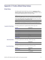
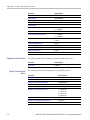
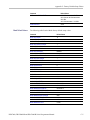
Appendix C: Factory Default Setup Values...................................................................
Default Setup ................................................................................................
Appendix D: GPIB Interface Specifications ..................................................................
Interface Messages .........................................................................................
GPIB Functions .............................................................................................
Glossary
Index
ii
3-3
3-4
3-5
3-6
A-1
B-1
C-1
C-1
D-1
D-1
D-2
DPO7000, DPO70000/B and DSA7000/B Series Programmer Manual
Preface
This programmer manual provides you with the information required to use GPIB
commands for remotely controlling your instrument.
Documentation
Quick Start User Manual. The user manual has information about
installing and operating the instrument. It also provides concepts and
theories about using the instrument that are not covered in the online help.
Online Help. This is an online help system that is integrated with the User
Interface application that ships with this product. The online help provides
in-depth operation and user interface help.
Getting Started with OpenChoice ™ Solutions Manual. A book that
explores some options for getting data from your instrument into any one
of several available analysis tools.
Specifications and Performance Verification. Instrument specifications
and a performance verification procedure. This is available as a printable
PDF file on the Product Software CD-ROM.
TekVISA Programmer Manual. This manual is available as a printable
PDF file on the Product Software CD-ROM. The manual describes
TekVISA, the Tektronix implementation of the VISA Application
Programming Interface (API). TekVISA is industry-compliant software
for writing interoperable instrument drivers in a variety of Application
Development Environments (ADEs).
Optional Applications Software for Tektronix Windows-Based
Instruments (CD-ROM). This CD-ROM contains trial versions of
application-specific programs that you can install and run five times per
application. To purchase an application, contact your local Tektronix
representative.
Other Included Documentation. Installation booklets are included in the
Product Software and Operating System Restore Software packages.
Service Manual. The service manual includes procedures to service the
instrument to the module level. This manual is available as a printable
PDF file on the Product Software CD-ROM.
DPO7000, DPO70000/B and DSA7000/B Series Programmer Manual
iii
Preface
The programmer guide is divided into the following major topics:
Getting Started. This topic introduces you to the programming information
and provides basic information about setting up your instrument for remote
control.
Command Groups. This topic contains all the commands listed in functional
groups. Each group consists of an overview of the commands in that group and
a table that lists all the commands and queries for that group. You can click a
command in the listing to display a detailed description of the command.
Command Syntax. This topic provides an overview of the command syntax
that you use to communicate with the instrument and other general information
about commands, such as how commands and queries are constructed, how to
enter commands, constructed mnemonics, and argument types.
Status and Events. This topic discusses the status and event reporting system
for the GPIB interfaces. This system informs you of certain significant events
that occur within the instrument. Topics that are discussed include registers,
queues, event handling sequences, synchronization methods, and messages
that the instrument may return, including error messages.
Miscellaneous. This topic contains miscellaneous information, such as a
list of reserved words, a table of the factory initialization (default) settings,
and interface specifications that may be helpful when using commands to
remotely control the instrument.
iv
DPO7000, DPO70000/B and DSA7000/B Series Programmer Manual
Getting Started
This programmer guide provides you with the information required to use GPIB
commands for remotely controlling your instrument. With this information, you
can write computer programs that will perform functions such as setting the front
panel controls, taking measurements, performing statistical calculations, and
exporting data for use in other programs, such as spreadsheets.
In addition to the traditional GPIB electronic interface (referred to as the physical
GPIB interface), your instrument is provided with a TekVISA GPIB-compatible
interface (referred to as the virtual GPIB interface). This is a software Application
Programming Interface (API) which enables you to communicate with the
instrument in a variety of ways, including via the Internet. With the following two
exceptions, these interfaces are completely independent:
HEADER. Command headers enabled or disabled on one interface are
correspondingly enabled or disabled on the other interface. Refer to the
command descriptions for more detailed information.
VERBOSE. Verbosity enabled or disabled on one interface is correspondingly
enabled or disabled on the other interface. Refer to the command description
for more detailed information.
Most examples in this document require that both HEADER and VERBOSE are ON.
Refer to Documentation for information on related manuals and documents.
Setting Up Remote Communications
Before setting up the instrument for remote communications using the electronic
(physical) GPIB interface, you should familiarize yourself with the following
GPIB requirements:
A unique device address must be assigned to each device on the bus. No two
devices can share the same device address.
No more than 15 devices can be connected to any one line.
One device should be connected for every 6 feet (2 meters) of cable used.
No more than 65 feet (20 meters) of cable should be used to connect devices
to a bus.
At least two-thirds of the devices on the network should be powered on while
using the network.
Connect the devices on the network in a star or linear configuration. Do not
use loop or parallel configurations.
DPO7000, DPO70000/B and DSA7000/B Series Programmer Manual
1-1
Getting Started
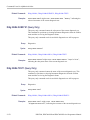
Connecting to the
Instrument
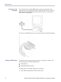
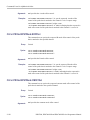
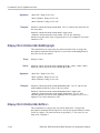
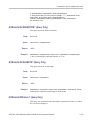
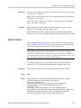
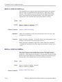
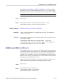
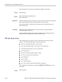
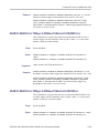
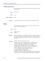
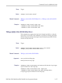
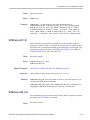
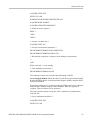
Your instrument has a 24-pin GPIB connector on its rear (side) panel. This
connector has a D-type shell and conforms to IEEE Std 488.1¾1987. Attach an
IEEE Std 488.1¾1987 GPIB cable to this connector and to your controller as
shown in the following figure.
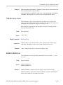
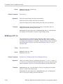
If necessary, the GPIB connectors can be stacked as shown in the following figure.
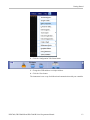
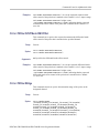
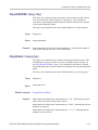
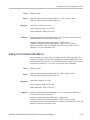
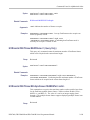
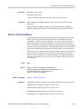
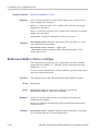
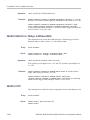
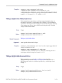
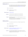
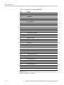
Setting the GPIB Address
To function correctly, your instrument must have a unique device address. The
default settings for the GPIB configuration are:
GPIB Address 1
GPIB ModeGPIB Talk/Listen
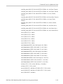
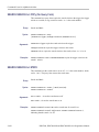
To change either of the GPIB settings, do the following:
1. Select GPIB Configuration from the Utilities menu.
1-2
DPO7000, DPO70000/B and DSA7000/B Series Programmer Manual
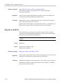
Getting Started
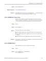
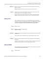
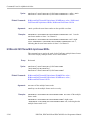
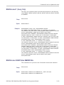
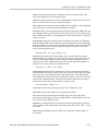
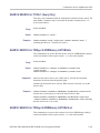
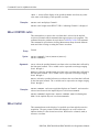
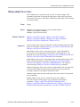
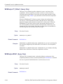
2. Click the Configuration Talk/Listen button.
3. Change the GPIB Address to a unique address.
4. Click the Close button.
The instrument is now set up for bidirectional communication with your controller.
DPO7000, DPO70000/B and DSA7000/B Series Programmer Manual
1-3
Getting Started
1-4
DPO7000, DPO70000/B and DSA7000/B Series Programmer Manual
Command Syntax
You can control the operations and functions of the instrument through the
GPIB interface using commands and queries. The following related topics listed
describe the syntax of these commands and queries. The topics also describe the
conventions that the instrument uses to process them. See the Command Groups
topic in the table of contents for a listing of the commands by command group, or
use the index to locate a specific command.
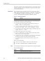
Backus-Naur Form Notation
This documentation describes the commands and queries using Backus-Naur
Form (BNF) notation. Refer to the following table for the symbols that are used.
Table 2-1: Symbols for Backus-Naur Form
Symbol
<>
Meaning
::=
Is defined as
|
Exclusive OR
Defined element
{}
Group; one element is required
[]
.. .
Optional; can be omitted
()
Comment
Previous element(s) may be repeated
Command and Query Structure
Commands consist of set commands and query commands (usually called
commands and queries). Commands modify instrument settings or tell the
instrument to perform a specific action. Queries cause the instrument to return
data and status information.
Most commands have both a set form and a query form. The query form of the
command differs from the set form by its question mark on the end. For example,
the set command ACQuire:MODe has a query form ACQuire:MODe?. Not all
commands have both a set and a query form. Some commands have set only and
some have query only.
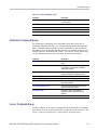
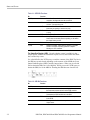
Messages
A command message is a command or query name followed by any information
the instrument needs to execute the command or query. Command messages may
contain five element types, defined in the following table.
DPO7000, DPO70000/B and DSA7000/B Series Programmer Manual
2-1
Command Syntax
Table 2-2: Command Message Elements
Commands
Symbol
Meaning
<Header>
This is the basic command name. If the header ends with a question
mark, the command is a query. The header may begin with a colon
(:) character. If the command is concatenated with other commands,
the beginning colon is required. Never use the beginning colon with
command headers beginning with a asterisk (*).
<Mnemonic>
This is a header subfunction. Some command headers have only one
mnemonic. If a command header has multiple mnemonics, a colon (:)
character always separates them from each other.
<Argument>
This is a quantity, quality, restriction, or limit associated with the header.
Some commands have no arguments while others have multiple
arguments. A <space> separates arguments from the header. A
<comma> separates arguments from each other.
<Comma>
A single comma is used between arguments of multiple-argument
commands. Optionally, there may be white space characters before
and after the comma.
<Space>
A white space character is used between a command header and the
related argument. Optionally, a white space may consist of multiple
white space characters.
Commands cause the instrument to perform a specific function or change one of
the settings. Commands have the structure:
[:]<Header>[<Space><Argument>[<Comma> <Argument>]...]
A command header consists of one or more mnemonics arranged in a hierarchical
or tree structure. The first mnemonic is the base or root of the tree and each
subsequent mnemonic is a level or branch off the previous one. Commands at a
higher level in the tree may affect those at a lower level. The leading colon (:)
always returns you to the base of the command tree.
2-2
DPO7000, DPO70000/B and DSA7000/B Series Programmer Manual
Command Syntax
Queries
Queries cause the instrument to return status or setting information. Queries
have the structure:
[:]<Header>?
[:]<Header>?[<Space><Argument> [<Coma><Argument>]...]
You can specify a query command at any level within the command tree unless
otherwise noted. These branch queries return information about all the mnemonics
below the specified branch or level. For example, HIStogram:STATistics:STDdev?
returns the standard deviation of the histogram, while HIStogram:STATistics?
returns all the histogram statistics, and HIStogram? returns all the histogram
parameters.
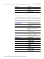
Headers
You can control whether the instrument returns headers as part of the query
response. Use the HEADer command to control this feature. If header is on,
the query response returns command headers, then formats itself as a valid set
command. When header is off, the response includes only the values. This may
make it easier to parse and extract the information from the response. The
following table shows the difference in responses.
Table 2-3: Comparison of Header Off and Header On Responses
Query
Header Off
Header On
TIME?
”14:30:00”
:TIME”14:30:00”
ACQuire:NUMAVg?
100
:ACQUIRE:NUMAVG 100
Clearing the Instrument
You can clear the Output Queue and reset the instrument to accept a new
command or query by using the selected Device Clear (DCL) GPIB function.
Refer to your GPIB library documentation for further details about the selected
Device Clear operation.
DPO7000, DPO70000/B and DSA7000/B Series Programmer Manual
2-3
Command Syntax
Command Entry
The following rules apply when entering commands:
You can enter commands in upper or lower case.
You can precede any command with white space characters. White space
characters include any combination of the ASCII control characters 00 through
09 and 0B through 20 hexadecimal (0 through 9 and 11 through 32 decimal).
The instrument ignores commands consisting of any combination of white
space characters and line feeds.
Abbreviating
You can abbreviate many instrument commands. Each command in this
documentation shows the abbreviations in capitals. For example, you can enter
the command ACQuire:NUMAvg simply as ACQ:NUMA or acq:numa.
Abbreviation rules may change over time as new instrument models are
introduced. Thus, for the most robust code, use the full spelling.
If you use the HEADer command to have command headers included as part
of query responses, you can further control whether the returned headers are
abbreviated or are full-length with the VERBose command.
Concatenating
2-4
You can concatenate any combination of set commands and queries using a
semicolon (;). The instrument executes concatenated commands in the order
received.
DPO7000, DPO70000/B and DSA7000/B Series Programmer Manual
Command Syntax
When concatenating commands and queries, you must follow these rules:
1. Separate completely different headers by a semicolon and by the beginning
colon on all commands except the first one. For example, the commands
TRIGger:MODe NORMal and ACQuire:NUMAVg 10, can be concatenated
into the following single command:
TRIGger:MODe NORMal;:ACQuire:NUMAVg 10
2. If concatenated commands have headers that differ by only the last mnemonic,
you can abbreviate the second command and eliminate the beginning colon.
For example, you can concatenate the commands ACQuire:MODe ENVelope
and ACQuire:NUMAVg 10 into a single command:
ACQuire:MODe ENVelope; NUMAVg 10
The longer version works equally well:
ACQuire:MODe ENVelope;:ACQuire:NUMAVg 10
3. Never precede a star (*) command with a colon:
ACQuire:MODe ENVelope;*OPC
Any commands that follow will be processed as if the star command was not
there so the commands, ACQuire:MODe ENVelope;*OPC;NUMAVg 10 will
set the acquisition mode to envelope and set the number of acquisitions for
averaging to 10.
4. When you concatenate queries, the responses to all the queries are
concatenated into a single response message. For example, if the display
imageview color is temperature and the display recordview color is spectral,
the concatenated query DISplay:COLOr:PALETTE:IMAGEVIEW?;
RECORDVIEW? will return the following.
If the header is on:
:DISPLAY:COLOR:PALETTE:IMAGEVIEW TEMPERATURE;
:DISPLAY:COLOR:PALETTE:RECORDVIEW SPECTRAL
If the header is off:
TEMPERATURE;SPECTRAL
5. Set commands and queries may be concatenated in the same message. For
example,
ACQuire:MODe SAMple;NUMAVg?;STATE?
is a valid message that sets the acquisition mode to sample. The message then
queries the number of acquisitions for averaging and the acquisition state.
Concatenated commands and queries are executed in the order received.
DPO7000, DPO70000/B and DSA7000/B Series Programmer Manual
2-5
Command Syntax
Here are some invalid concatenations:
DISplay:PERSistance:RESET;ACQuire:NUMAVg 10 (no colon before
ACQuire)
DISplay:GRAticule FULl;:FILTer SINX (extra colon before FILTer; use
DISplay:GRAticule FULl;FILTer SINX instead)
DISplay:PERSistance:RESET;:*OPC (colon before a star (*) command)
DISplay:COLOr:MATHCOLOr DEFAULT;COLOr:REFCOLOr INHERIT (levels
of the mnemonics are different; either remove the second use of COLor or place
:DISPlay: in front of COLOr:REFCOLOr INHERIT)
Terminating
This documentation uses <EOM> (End of message) to represent a message
terminator.
Table 2-4: End of Message Terminator
Symbol
Meaning
<EOM>
Message terminator
The end-of-message terminator must be the END message (EOI asserted
concurrently with the last data byte). The last data byte may be an ASCII linefeed
(LF) character.
This instrument does not support ASCII LF only message termination. The
instrument always terminates outgoing messages with LF and EOI.
Constructed Mnemonics
Some header mnemonics specify one of a range of mnemonics. For example, a
channel mnemonic can be CH1, CH2, CH3, or CH4. You use these mnemonics
in the command just as you do any other mnemonic. For example, there is a
CH1:POSition command, and there is also a CH2:POSition command. In the
command descriptions, this list of choices is abbreviated as CH<x>.
Cursor Position
Mnemonics
When cursors are displayed, commands may specify which cursor of the pair to
use.
Table 2-5: Cursor Mnemonics
2-6
Symbol
Meaning
CURSOR<x>
A cursor selector; <x> is either 1 or 2.
POSITION<x>
A cursor selector; <x> is either 1 or 2.
HPOS<x>
A cursor selector; <x> is either 1 or 2.
DPO7000, DPO70000/B and DSA7000/B Series Programmer Manual
Command Syntax
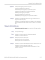
Math Specifier Mnemonics
Commands can specify the mathematical waveform to use as a mnemonic in
the header.
Table 2-6: Math Specifier Mnemonics
Measurement Specifier
Mnemonics
Symbol
Meaning
Math<x>
A math waveform specifier; <x> is 1 through 4.
Commands can specify which measurement to set or query as a mnemonic in the
header. Up to eight automated measurements may be displayed.
Table 2-7: Measurement Specifier Mnemonics
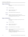
Channel Mnemonics
Symbol
Meaning
MEAS<x>
A measurement specifier; <x> is 1 through 8.
Commands specify the channel to use as a mnemonic in the header.
Table 2-8: Channel Mnemonics
Reference Waveform
Mnemonics
Symbol
Meaning
CH<x>
A channel specifier; <x> is 1 through 4.
Commands can specify the reference waveform to use as a mnemonic in the
header.
Table 2-9: Reference Waveform Mnemonics
Symbol
Meaning
REF<x>
A reference waveform specifier; <x> is 1 thru 4.
Argument Types
Numeric
Many instrument commands require numeric arguments. The syntax shows the
format that the instrument returns in response to a query. This is also the preferred
format when sending the command to the instrument though any of the formats
will be accepted. This documentation represents these arguments as follows:
Table 2-10: Numeric Arguments
Symbol
Meaning
<NR1>
Signed integer value
<NR2>
Floating point value without an exponent
<NR3>
Floating point value with an exponent
DPO7000, DPO70000/B and DSA7000/B Series Programmer Manual
2-7
Command Syntax
Most numeric arguments will be automatically forced to a valid setting, either by
rounding or truncating, when an invalid number is input unless otherwise noted
in the command description.
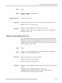
Quoted String
Some commands accept or return data in the form of a quoted string, which is
simply a group of ASCII characters enclosed by a single quote (’) or double quote
("). The following is an example of a quoted string: "This is a quoted
string". This documentation represents these arguments as follows:
Table 2-11: Quoted String Argument
Symbol
Meaning
<QString>
Quoted string of ASCII text
A quoted string can include any character defined in the 7-bit ASCII character
set. Follow these rules when you use quoted strings:
1. Use the same type of quote character to open and close the string. For
example: "this is a valid string".
2. You can mix quotation marks within a string as long as you follow the
previous rule. For example, "this is an ’acceptable’ string".
3. You can include a quote character within a string by repeating the quote. For
example: "here is a "" mark".
4. Strings can have upper or lower case characters.
5. If you use a GPIB network, you cannot terminate a quoted string with the
END message before the closing delimiter.
6. A carriage return or line feed embedded in a quoted string does not terminate
the string, but is treated as just another character in the string.
7. The maximum length of a quoted string returned from a query is 255
characters.
Here are some invalid strings:
"Invalid string argument’ (quotes are not of the same type)
"test<EOI>" (termination character is embedded in the string)
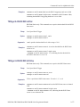
Block
Several instrument commands use a block argument form (see the following table).
Table 2-12: Block Argument
2-8
Symbol
Meaning
<NZDig>
A nonzero digit character in the range of 1–9
<Dig>
A digit character, in the range of 0–9
DPO7000, DPO70000/B and DSA7000/B Series Programmer Manual
Command Syntax
Table 2-12: Block Argument (cont.)
Symbol
Meaning
<DChar>
A character with the hexadecimal equivalent of 00 through FF (0
through 255 decimal)
<Block>
A block of data bytes defined as: <Block> ::=
{#<NZDig><Dig>[<Dig>...][<DChar>...]
|#0[<DChar>...]<terminator>}
<NZDig> specifies the number of <Dig> elements that follow. Taken together,
the <NZDig> and <Dig> elements form a decimal integer that specifies how
many <DChar> elements follow.
NOTE. The digit <NZDig> is in hexadecimal format. This deviates slightly from
the IEEE 488.2 specification that it be in decimal format, as extra allowances
must be made for data lengths that are greater than 999,999,999 <DChar>
elements (for example 500M record lengths at 2 bytes per point).
DPO7000, DPO70000/B and DSA7000/B Series Programmer Manual
2-9
Command Syntax
2-10
DPO7000, DPO70000/B and DSA7000/B Series Programmer Manual
Command Groups
The programmable interface conforms to Tektronix standard codes and formats
except where noted. The GPIB interface also conforms to IEEE Std 488.2-1987
except where noted.
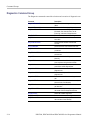
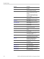
Acquisition Command Group
Use the commands in the Acquisition Command Group to set up the modes and
functions that control how the instrument acquires the signals you input to the
channels and processes them into waveforms.
Using these commands for acquiring waveforms, you can do the following:
Start and stop acquisitions.
Control whether each waveform is simply acquired, averaged, or enveloped
over successive acquisitions of that waveform.
Set the controls or conditions that start and stop acquisitions.
Determine the action the system takes upon completing an acquisition, such
as saving all waveforms and taking a measurement when the acquisition is
stopped.
Control acquisition of acquired channel waveforms.
Set acquisition parameters.
Table 2-13: Acquisition Commands
Command
Description
ACQuire?
Returns acquisition parameters
ACQuire:INTERPEightbit
Sets or returns the interpolation acquisition
mode
ACQuire:MODe
Sets or returns acquisition mode
ACQuire:NUMFRAMESACQuired?
Returns the number of acquisitions that have
occurred
ACQuire:NUMACq?
Returns the number of waveform acquisitions
that have occurred since starting acquisition
with the ACQuire:STATE RUN command
ACQuire:NUMAVg
Sets or returns number of acquisitions for an
averaged waveform
ACQuire:NUMEnv
Sets or returns number of acquisitions for
envelope waveform
ACQuire:NUMSAMples
Sets or returns the number of samples that
make up a WfmDB for single sequence
mode and Mask Pass/Fail Completion Test
DPO7000, DPO70000/B and DSA7000/B Series Programmer Manual
2-11
Command Groups
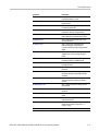
Table 2-13: Acquisition Commands (cont.)
Command
Description
ACQuire:SAMPlingmode
This command sets or queries the sampling
mode
ACQuire:STATE
Starts, stops, or returns acquisition state
ACQuire:STOPAfter
Sets or returns whether the acquisition is
continuous or single sequence
FASTAcq?
Enables, disables, or returns state of Fast
Acquisition mode
FASTAcq:HIACQRATE
Sets or returns the state of FastAcq
optimization for capturing the details with a
higher sample rate
FASTAcq:STATE
Returns the Fast Acquisition state
Alias Command Group
Alias commands allow you to define new commands as a sequence of standard
commands. You may find this useful when repeatedly using the same commands
to perform certain tasks like setting up measurements.
Aliases are similar to macros but do not include the capability to substitute
parameters into alias bodies. The alias mechanism obeys the following rules:
The alias name must consist of a valid IEEE 488.2 message unit, which may
not appear in a message preceded by a colon, comma, or a command or query
program header.
The alias name may not appear in a message followed by program date, a
colon, comma, or question mark.
An alias name must be distinct from any keyword or keyword short form.
An alias name cannot be redefined without first being deleted using one of
the alias deletion functions.
Alias names do not appear in response messages.
The Alias commands are defined in Tektronix Standard Codes and Formats.
Deviations between that standard and what is specified here will be considered
errors unless specifically noted in the command description in this document.
Table 2-14: Alias Commands
2-12
Command
Description
ALIas
Sets or returns the alias state
ALIas:CATalog?
Returns a list of the currently defined alias
labels
DPO7000, DPO70000/B and DSA7000/B Series Programmer Manual
Command Groups
Table 2-14: Alias Commands (cont.)
Command
Description
ALIas:DEFine
Assigns a sequence of program messages
to an alias label
ALIas:DELEte
Removes a specified alias
ALIas:DELEte:ALL
Deletes all existing aliases
ALIas:DELEte:NAMe
Removes a specified alias
ALIas:STATE
Sets or returns the alias state
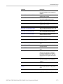
Calibration Command Group
The Calibration commands provide information about the current state of
instrument calibration and allow you to initiate internal signal path calibration
(SPC). Commands that are specific to factory calibration are not described in
this manual; however, they are described in the service manual (located on your
Product Software CD-ROM in PDF format). You can also order a printed copy
(see Recommended Accessories in the online help for the instrument).
Command
Description
CALibrate?
Returns the internal and factory calibration
status
*CAL?
Instructs the instrument to perform
self-calibration and returns the calibration
status when complete
CALibrate:CALProbe:CH<x>?
Performs a probe calibration for the selected
channel and returns the calibration status
CALibrate:INTERNal
Starts the internal signal path calibration
CALibrate:INTERNal:STARt
Starts the internal signal path calibration
CALibrate:INTERNal:STATus?
Returns the current status of the internal
signal path calibration
CALibrate:PRObestate:CH<x>?
Returns the probe calibration status for the
probe of the selected channel
CALibrate:RESults?
Returns the status of all calibration
subsystems without performing an SPC
operation
CALibrate:RESults:SPC?
Returns the results of the last SPC operation
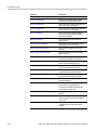
Cursor Command Group
Use the commands in the Cursor Command Group to control the cursor display
and readout. You can use these commands to control the setups for cursor 1 and
cursor 2, such as waveform source, cursor position, and cursor color.
DPO7000, DPO70000/B and DSA7000/B Series Programmer Manual
2-13
Command Groups
You can also use the commands to select one of the following cursor functions:
Off. Shuts off the display of all cursors.
Vertical Bars. Displays vertical bar cursors, which provide traditional
horizontal unit readouts for Cursor 1 (bar1), Cursor 2 (bar2), the delta between
them, and 1/delta (results in frequency when the horizontal unit is time).
Horizontal Bars. Displays horizontal bar cursors, which provide traditional
vertical unit readouts for Cursor 1 (bar1), Cursor 2 (bar2), and the delta
between them.
Waveform Cursors. Consists of two cursors you can independently assign to
a waveform. These cursors provide the same readouts that the vertical and
horizontal bar cursors provide. Waveform cursors enable you to conveniently
measure waveform amplitude and time. In XY or XYZ format, waveform
cursors indicate the amplitude position of an XY pair (Ch1 vs Ch2 voltage,
where Ch1 is the X axis and Ch2 is the Y axis) relative to the trigger.
Screen Cursors. Consists of two pairs of independent horizontal and vertical
cursors. You can use these cursors to indicate an arbitrary position within
the waveform display area. Screen cursors, depending on the style selected,
consist of the intersection of a vertical and horizontal line, an X, or a vertical
line with an X. These cursors have no association with any waveform, other
than they inherit the color of the waveform they are assigned too.
2-14
Command
Description
CURSor?
Returns all cursor settings
CURSor:FUNCtion
Sets or returns the cursor type
CURSor:HBArs?
Returns hbar cursor settings
CURSor:HBArs:DELTa?
Returns hbars cursors vertical difference
CURSor:HBArs:POSITION<x>
Sets or returns the hbar cursor<x> vertical
position
CURSor:HBArs:UNIts?
Returns hbar cursor units
CURSor:LINESTyle
Sets or returns the cursor line style
CURSor:MODe
Sets or returns whether cursors move in
unison or separately
CURSor:SCREEN:STYle
Sets or returns the cursor type for screen
mode
CURSor:SCREEN:XPOSITION<x>
Sets or queries the x position of the specified
screen cursor
CURSor:SCREEN:YPOSITION<x>
Sets or queries the y position of the specified
screen cursor
CURSor:SOUrce<x>
Sets or returns the source for cursor <x>
CURSor:STATE
Turns cursors on or off or returns their state
CURSor:VBArs
Sets or returns the position of vertical bar
cursors
DPO7000, DPO70000/B and DSA7000/B Series Programmer Manual
Command Groups
Command
Description
CURSor:VBArs:DELTa?
Returns the difference between vbar cursors
CURSor:VBArs:POSITION<x>
Sets or returns the vbar cursor<x> horizontal
position
CURSor:VBArs:POS<x>
Sets or queries the horizontal position for
vertical bar cursors
CURSor:VBArs:UNIts
Sets or returns the units for vbar cursors
CURSor:WAVEform
Sets or returns the current settings for
waveform cursors
CURSor:WAVEform:HDELTA?
Returns the horizontal difference between
waveform cursors
CURSor:WAVEform:HPOS<x>?
Returns the position of waveform cursor <x>
CURSor:WAVEform:POSition<x>
Sets or returns the position of waveform
cursor <x>
CURSor:WAVEform:STYle
Sets or returns the cursor type for waveform
mode
CURSor:WAVEform:UNIts
Sets or returns the units for waveform cursors
CURSor:WAVEform:VDELTA?
Returns the vertical difference between
waveform cursors
CURSor:XY?
Returns the current settings for XY cursors
CURSor:XY:PRODDELta?
Returns the product of the difference
between the cursors X positions and Y
positions
CURSor:XY:PRODUCT<x>?
Returns the product of the X and Y positions
for the specified cursor
CURSor:XY:RADIUS<x>?
Returns the radius of the specified cursor
CURSor:XY:RATDELta?
Returns ratio of the difference between the
cursors X position and Y position
CURSor:XY:RATIO<x>?
Returns ratio of the X (horizontal) and Y
(vertical) position for the specified cursor
CURSor:XY:RDELta?
Returns the Dr value
CURSor:XY:READOUT
Sets or returns the XY cursor readout mode
CURSor:XY:RECTX<x>
Sets or returns the X cursor position in
rectangular coordinates
CURSor:XY:RECTY<x>
Sets or returns the Y cursor position in
rectangular coordinates
CURSor:XY:THDELta?
Returns the XY cursor angle delta in polar
coordinates
CURSor:XY:THETA<x>?
Returns the XY cursor angle in polar
coordinates
CURSor:XY:XDELta?
Returns the XY cursor ΔX value in
rectangular coordinates
CURSor:XY:YDELta?
Returns the XY cursor ΔY value in
rectangular coordinates
DPO7000, DPO70000/B and DSA7000/B Series Programmer Manual
2-15
Command Groups
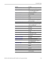
Diagnostics Command Group
The Diagnostic commands control the selection and execution of diagnostic tests.
2-16
Command
Description
DIAg:CONTROL:HALT
Enables or disables halting on first diagnostic
failure
DIAg:CONTROL:LOOP
Enables or disables looping of diagnostics
DIAg:FAILURES:CLEAR
Sets and returns the clearing of pass/fail
information from data structures, not the
Event Log, at the start of diagnostic tests
DIAg:EXECUTE
Executes currently selected set of diagnostics
DIAg:ITEM?
Returns all data associated with a selected
menu item
DIAg:ITEM:FAILURES?
Returns the total number of failures that
occurred
DIAg:ITEM:NAMe?
Returns the name of the selected menu item
DIAg:ITEM:RESULT?
Returns the results of the last test executed
on this item
DIAg:ITEM:SUBITEMS?
Returns the number of subitems associated
with this item
DIAg:LEVEL
Sets the current level of diagnostic test
hierarchy
DIAg:LOOPS?
Returns the number of times the diagnostics
were completed during the last execution
DIAg:NAMe?
Returns the subsystem name, area, and test
name of the current diagnostic test
DIAg:NAMe:AREA?
Returns the selected area of the current
diagnostic test
DIAg:NAMe:SUBSYS?
Returns the subsystem of the current
diagnostic test
DIAg:NAMe:TEST?
Returns the name of the current diagnostic
test
DIAg:NUMITEMS?
Returns the number of items on the currently
selected level of test hierarchy
DIAg:RESults?
Returns a brief pass or fail status of the last
test execution
DIAg:RESults:VERBose?
Returns a more explanatory message about
the results of the last diagnostic execution
DIAg:SELect:ALL
Selects all available diagnostics
DIAg:SELect:AREA
Selects one of the available diagnostic areas
DIAg:SELect:LAST
Sets the last item of a group of items from
the same level of test hierarchy
DPO7000, DPO70000/B and DSA7000/B Series Programmer Manual
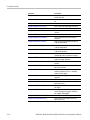
Command Groups
Command
Description
DIAg:SELect:SUBSYS
Selects one of the available diagnostic
subsystems
DIAg:SELect:TEST
Selects one of the available diagnostic tests
DIAg:STATE
Sets the instrument operating state
DIAg:STOP
Terminates the execution of diagnostics
TEST
Selects and executes an item at any level
of the test hierarchy
TEST:RESults?
Returns a brief pass or fail status of the last
test execution
TEST:RESults:VERBose?
Returns a more explanatory message about
the results of the last test execution
TEST:STOP
Terminates the execution of the test
Display Control Command Group
Use the commands in the Display Control Command Group to change the
graticule style, the displayed intensities, and to set the characteristics of the
waveform display.
You can set the display of date and time; cursor, histogram, mask, and
measurement readouts; measurement annotations, and the mode in which
waveforms are displayed.
There are six color palettes from which you can select:
Normal. Displays hues and lightness levels for best overall viewing.
Temp. Displays areas of the waveform with the highest sample density in
warmer colors (red shades) while the areas of lowest sample density appear in
cooler colors (blue shades).
Spectral. Displays areas of the waveform with the highest sample density in
blue shades while the areas of lowest sample density appear in red shades.
Green. Displays waveforms in shades of green. Areas of the waveform with
the highest sample density appear in lighter green shades while the areas of
lowest sample density appear in darker green shades.
Gray. Displays waveforms in shades of gray. Areas of the waveform with
the highest sample density appear in lighter gray shades while the areas of
lowest sample density appear in darker gray shades.
User Allows you to create a customized color palette.
Use the commands to set the style that best displays your waveforms and graticule
display properties.
DPO7000, DPO70000/B and DSA7000/B Series Programmer Manual
2-17
Command Groups
NOTE. The mode you choose globally affects all displayed waveforms.
2-18
Command
Description
DISplay?
Returns current display settings
DISplay:CLOCk
Sets or returns the display of the date/time
stamp
DISplay:COLOr?
Returns color group settings
DISplay:COLOr:MATHCOLOr
Sets or returns the color to be used for math
traces
DISplay:COLOr:PALEtte:IMAGEView
Sets or returns the color palette for imageview
waveforms
DISplay:COLOr:PALEtte:RECORDView
Sets or returns the color palette for
recordview waveforms
DISplay:COLOr:PALEtte:USEr
Returns the user palette group settings
DISplay:COLOr:PALEtte:USEr:CARet
Sets or returns the user caret color
DISplay:COLOr:PALEtte:USEr:CH<x>
Sets or returns the user palette channel
colors
DISplay:COLOr:PALEtte:USEr:GRAticule
Sets or returns the user palette graticule
DISplay:COLOr:PALEtte:USEr:HIStogram
Sets or returns the user palette histogram
color
DISplay:COLOr:PALEtte:USEr:MASK
Sets or returns the user palette mask color
DISplay:COLOr:PALEtte:USEr:
MASKHighlight
Sets or returns the user palette mask hits
color
DISplay:COLOr:PALEtte:USEr:MATH<x>
Sets or returns the user palette math colors
DISplay:COLOr:PALEtte:USEr:REF<x>
Sets or returns the user palette reference
colors
DISplay:COLOr:PALEtte:USEr:WAVEform
Sets or queries the user palette waveform
colors
DISplay:COLOr:REFCOLOr
Sets or returns the color to be used for
reference traces
DISplay:FILTer
Sets or returns the type of interpolation to
use for the display
DISplay:FORMat
Sets or returns the display format
DISplay:GRAticule
Sets or returns the type of graticule that is
displayed
DISplay:INTENSITy?
Returns the waveform and graticule
saturation levels
DISplay:INTENSITy:WAVEform:IMAGEView
Sets or returns the waveform saturation level
for imageview waveforms
DISplay:INTENSITy:WAVEform:
RECORDView
Sets or returns the waveform saturation level
for recordview waveforms
DISplay:PERSistence
Sets or returns display persistence setting
DPO7000, DPO70000/B and DSA7000/B Series Programmer Manual
Command Groups
Command
Description
DISplay:PERSistence:RESET
Clears the persistence data
DISplay:SCREENTExt?
Returns all screen text settings
DISplay:SCREENTExt:LABel<x>?
Sets or returns the screen text setting for a
given label
DISplay:SCREENTExt:LABel<x>:
FONTCOlor
Sets or queries the screen text label font color
DISplay:SCREENTExt:LABel<x>:
FONTNAme
Sets or queries the screen text label font
name for a given label
DISplay:SCREENTExt:LABel<x>:FONTSIze
Sets or queries the screen text label font size
for a given label
DISplay:SCREENTExt:LABel<x>:
FONTSTyle
Sets or queries the screen text label font
style for a given label
DISplay:SCREENTExt:LABel<x>:NAMe
Sets the text to be displayed for a given label
DISplay:SCREENTExt:LABel<x>:STATE
Sets or queries the screen text label state for
a given label
DISplay:SCREENTExt:LABel<x>:XPOS
Sets or returns the horizontal position of a
given label
DISplay:SCREENTExt:LABel<x>:YPOS
Sets or returns the vertical position of a given
label
DISplay:SCREENTExt:STATE
Sets or returns the state of the display of
screen text
DISplay:SHOWREmote
Sets or queries the state of the remote
display feature and is equivalent to selecting
Display Remote from the Display menu
DISplay:STYle
Sets or returns data display style
DISplay:TRIGBar
Sets or returns the display setting of the
trigger level indicator bar(s)
DISplay:TRIGT
Sets or returns the display of the trigger point
indicator
DISplay:VARpersist
Sets or returns the persistence decay time
DISplay:WAVEform
Sets or returns the display of waveform
traces
E-mail Command Group
Commands in the E-mail group allow you to send e-mail to one or more
designated recipients whenever a selected event, such as a trigger, mask test
failure (Option MTM only), or a limit test failure occurs in the instrument.
Using this feature, you do not have to continually monitor the instrument for
the event.
DPO7000, DPO70000/B and DSA7000/B Series Programmer Manual
2-19
Command Groups
When an event occurs, the instrument will send an SMTP mail message to one or
more designated recipients through the specified mail server. The message can
include any of the following:
Screen image
Waveform data
Measurement data at the time of the event
NOTE. Your instrument must be connected to the Local Area Network (LAN)
using Transfer C Protocol/Internet Protocol (TCP/IP). The recipient must also
have an SMTP mail server. To send e-mail for a mask test failure, you must have
Mask Testing (Option MTM) installed.
2-20
Command
Description
EMail
Sends a test e-mail message or sets the
current e-mail sent count to zero
EMail:ATTempts
Sets or queries the number of times that an
attempt will be made to send e-mail to the
SMTP e-mail server
EMail:AUTHLogin
Sets or queries the login name that will be
used if the SMTP e-mail server requires one
for authentication
EMail:AUTHPassword
Sets the password that will be used if
the SMTP e-mail server requires one for
authentication
EMail:COUNt?
Returns the number of e-mails that have
been sent since Email on Event was armed
EMail:FROm
Sets or queries the From line in the e-mail
EMail:HOSTwanted
Sets or queries the hostname that will be
used when e-mail is sent to the SMTP e-mail
server
EMail:IMAGe
Sets or queries whether image data is
included in the e-mail
EMail:MASK
Sets or queries whether e-mail is sent when
a mask test failure occurs
EMail:MAXSize
Sets or queries the maximum size (in
megabytes) of e-mail that can be sent to the
SMTP server
EMail:MEASUrement
Sets or queries whether measurement data
is included in the e-mail
EMail:NUMEMails
Sets or queries the number e-mails that can
be sent when Email onEvent is armed
EMail:SMTPPort
Sets or queries the SMTP port number that
the e-mail server uses
DPO7000, DPO70000/B and DSA7000/B Series Programmer Manual
Command Groups
Command
Description
EMail:SMTPServer
Sets or queries the address of the SMTP
mail server
EMail:STATUS?
Queries the status of e-mail
EMail:TIMEOut
Sets or queries the global timeout in seconds
EMail:TO
Sets or queries the address of the
recipient(s) of an e-mail. Multiple addresses
are separated with a semicolon (;)
EMail:TRIGger
Sets or queries whether e-mail is sent when
a trigger occurs
EMail:WAVEform
Sets or queries whether waveform data is
included in the e-mail
File System Command Group
Use the commands in the File System Command Group to help you use the
built-in hard disk drive. You can use the commands to do the following:
List the contents of the default directory
Create and delete directories
Create, copy, read, rename, or delete a file
When using these commands, keep the following points in mind:
File arguments are always enclosed within double quotes:
“C:\MYDIR\TEK00001.SET”
File names follow the MSDOS format: [DRIVE:][\PATH\]filename
Path separators may be either forward slashes (/) or back slashes (\)
NOTE. Using back slash as a path separator may produce some unexpected
results, depending on how your controller application treats escaped characters.
Many applications recognize the sequence of back slash followed by an alphabetic
character as an escaped character, and, as such, interpret that alphabetic
character as a control character. For example, the sequence “\n” may be
interpreted as a newline character; “\t” may be interpreted as a tab character. To
ensure that this interpretation does not occur, you can use double back slashes.
For example, “C:\\testfile.txt”.
Some FILESystem commands may fail because a file has read-only attributes.
You will not be able to delete or replace such files until this attribute is
removed. Refer to the operating system help on file properties for further
information.
DPO7000, DPO70000/B and DSA7000/B Series Programmer Manual
2-21
Command Groups
Command
Description
FILESystem?
Returns the file system state
FILESystem:COPy
Copies one or more files to a new file
FILESystem:CWD
Sets or returns the current working directory
for FILESystem GPIB commands
FILESystem:DELEte
Deletes a named file or directory
FILESystem:DIR?
Returns a list of directory contents
FILESystem:MKDir
Makes a new directory
FILESystem:PRInt
Prints a named file to the named port
FILESystem:READFile
Copies the named file to the GPIB port
FILESystem:REName
Assigns a new name to an existing file
FILESystem:RMDir
Deletes the named directory
FILESystem:WRITEFile
Copies the GPIB port block data to a named
file
Hard Copy Command Group
Hard Copy commands enable you to make hard copies of data files or send the
data to a specified file. In addition, these commands provide you with information
about (and the ability to set) file path settings.
2-22
Command
Description
EXPort
Copies a waveform to a specified file or
returns formatting and file information
EXPort:FILEName
Sets or returns the export file path
EXPort:FORMat
Sets or returns the export image format
EXPort:PALEtte
Sets or returns the export color palette
EXPort:READOuts
Sets or returns the position of the readouts
for export
EXPort:VIEW
Sets or returns the export screen capture
area
HARDCopy
Sends a screen copy to the selected port or
returns the selected port and file path
HARDCopy:FILEName
Sets or returns the hard copy file path
HARDCopy:LAYout
Sets or returns the page orientation for hard
copy
HARDCopy:PALEtte
Sets or returns the hard copy color palette
HARDCopy:PORT
Sets or returns whether the hard copy data
will be sent to a file or printed on the next
hard copy command
DPO7000, DPO70000/B and DSA7000/B Series Programmer Manual
Command Groups
Command
Description
HARDCopy:READOuts
Sets or returns the position of the readouts
for hardcopy
HARDCopy:VIEW
Sets or returns the area of the screen to be
hardcopied
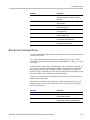
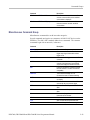
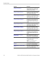
Histogram Command Group
Histogram commands let you select the type of histogram, what part of the
waveform should go into the histogram, and histogram statistics. Use commands
from this group to do the following:
Create a histogram of vertical or horizontal values for a channel, math, or
reference waveform
Adjust the limits of the waveform area from which the histogram data is
obtained
Clear histogram count and restart
Retrieve the histogram data
Command
Description
HIStogram?
Returns all histogram parameters
HIStogram:BOX
Sets or returns the left, top, right, and bottom
positions of the histogram box, in source
waveform coordinates
HIStogram:BOXPcnt
Sets or returns same as HIStogram:BOX, but
in percentage coordinates, with 0,0 upper left
and 100,100 lower right
HIStogram:COUNt
Clears histogram count source data and
restarts counting
HIStogram:DATa?
Returns a comma-separated list of histogram
data numbers
HIStogram:DISplay
Sets or returns whether histogram data is
displayed and the current display type setting
HIStogram:FUNCtion
Sets the type of histogram to create
Or returns the current histogram type
HIStogram:MODe
Sets type of histogram to create or turns
histograms off
Or returns the current histogram type or that
histogram display is disabled
HIStogram:SIZe
Sets or returns the width (or height) of the
histogram on the screen in divisions
DPO7000, DPO70000/B and DSA7000/B Series Programmer Manual
2-23
Command Groups
Command
Description
HIStogram:SOUrce
Sets or returns which source waveform will
be compared against the histogram box
when the histogram testing is enabled
HIStogram:STATE
Sets or returns whether histogram
calculations are enabled
Horizontal Command Group
Horizontal commands control the time bases of the instrument. You can set the
time per division (or time per point) of the main time base. You can use the
Horizontal commands to do the following:
Set the scale, horizontal position and reference, and units of the time base
Get the screen resolution, time of first point and time of last point, or get all
the horizontal settings
Enable or disable the display of the time base
You may substitute SECdiv for SCAle in the horizontal commands. This provides
program compatibility with earlier models of Tektronix instruments.
Command
Description
HORizontal?
Returns all learnable settings for the
horizontal commands
HORizontal:ACQDURATION?
Returns the time base duration
HORizontal:ACQLENGTH?
Returns the record length
HORizontal:DIVisions?
Returns the number of graticule divisions
over which the waveform is displayed
HORizontal:FASTframe?
Returns all settings for the horizontal
FastFrame commands
HORizontal:FASTframe:COUNt
Sets or returns the FastFrame frame count
Sets or returns the horizontal record length
to the number of sample points in each frame
2-24
HORizontal:FASTframe:MAXFRames?
Returns the maximum number of FastFrame
frames which can be acquired at the current
frame length
HORizontal:FASTframe:MULtipleframes:
FRAMESTart:<wfm>
Sets or returns the start frame number on the
specified waveform for FastFrame multiple
frames
HORizontal:FASTframe:MULtipleframes:
MODe
Sets or returns the mode for FastFrame
multiple frames
HORizontal:FASTframe:MULtipleframes:
NUMFRames:<wfm>
Sets or returns the number of frames on the
specified waveform for FastFrame multiple
frames
DPO7000, DPO70000/B and DSA7000/B Series Programmer Manual
Command Groups
Command
Description
HORizontal:FASTframe:REF:FRAme
Sets or returns the FastFrame reference
frame number
HORizontal:FASTframe:REF:SOUrce
Sets or returns the FastFrame Reference
waveform source
HORizontal:FASTframe:SELECTED:CH<x>
Sets or returns the FastFrame selected
frame number on the specified waveform
HORizontal:FASTframe:SELECTED:
MATH<x>
Sets or returns the FastFrame selected
frame number on the specified waveform.
HORizontal:FASTframe:SELECTED:
REF<x>
Sets or returns the FastFrame selected
frame number on the specified waveform
HORizontal:FASTframe:SELECTED:
SOUrce
Sets or returns the FastFrame source
waveform
HORizontal:FASTframe:SEQuence
Sets or returns the FastFrame source
waveform
HORizontal:FASTframe:STATE
Sets or returns the state of FastFrame
acquisition
HORizontal:FASTframe:SUMFrame
Sets or returns the summary frame mode
HORizontal:FASTframe:TIMEStamp:ALL:
<wfm>?
Returns the frame number and time stamp
for each frame between requested frames,
inclusive, within the specified waveform
HORizontal:FASTframe:TIMEStamp:
BETWeen:<wfm>?
Returns the relative trigger for the delta time
between the specified frames, within the
specified waveform
HORizontal:FASTframe:TIMEStamp:DELTa:
<wfm>?
Returns the relative time between the
triggers of the FastFrame Selected and the
FastFrame Reference, within the specified
waveform
HORizontal:FASTframe:TIMEStamp:
FRAMe:<wfm>?
Returns the absolute trigger date and time
for the specified frame and waveform
HORizontal:FASTframe:TIMEStamp:REF?
Returns the absolute trigger date and time for
the FastFrame specified reference waveform
HORizontal:FASTframe:TIMEStamp:
SELECTED:<wfm>?
Returns the absolute trigger date and time for
the FastFrame Selected, within the specified
waveform
HORizontal:FASTframe:TRACk
Sets up or returns the state of FastFrame
tracking
HORizontal:FASTframe:XZEro:ALL:CH<x>?
Returns the time from the trigger to the start
of the specified frames on the specified
channel
HORizontal:FASTframe:XZEro:ALL:
REF<x>?
Returns the time from the trigger to the start
of the specified frames on the specified
reference
DPO7000, DPO70000/B and DSA7000/B Series Programmer Manual
2-25
Command Groups
2-26
Command
Description
HORizontal:FASTframe:XZEro:FRAme:
CH<x>?
Returns the time from the trigger to the
start of the specified frame on the specified
channel
HORizontal:FASTframe:XZEro:FRAme:
REF<x>?
Returns the time from the trigger to the
start of the specified frame on the specified
reference
HORizontal:FASTframe:XZEro:REF?
Sets or returns the time from the trigger to the
trigger sample on the reference waveform
HORizontal:FASTframe:XZEro:SELECTED:
CH<x>?
Sets or returns the time from the trigger to
the trigger sample on the selected channel
HORizontal:FASTframe:XZEro:SELECTED:
REF<x>?
Sets or returns the time from the trigger to
the trigger sample on the selected reference
waveform
HORizontal:MAIn?
Returns the time per division of the main
time base
HORizontal[:MAIn]:DELay:MODe
Sets or returns the main time base trigger
delay mode
HORizontal[:MAIn]:DELay:POSition
Sets or returns the main time base position
when Horizontal Delay Mode is turned off
HORizontal[:MAIn]:DELay:TIMe
Sets or returns the main time base trigger
delay time
HORizontal:MAIn:INTERPRatio?
Returns the main horizontal time base
interpolation ratio
HORizontal[:MAIn]:POSition
Sets or returns the waveform horizontal
position on the display
HORizontal:MAIn:UNIts
Sets or returns the units for the horizontal
time base
HORizontal:MAIn:UNIts:STRing
Sets or returns the units string for the
horizontal main time base trigger delay
HORizontal:MODE
Sets or queries the horizontal mode. Auto
mode is the factory default
HORizontal:MODE:AUTO:LIMITrecordlen
Sets or queries the record length limit used
by the auto horizontal mode
HORizontal:MODE:RECOrdlength
Sets or queries the record length
HORizontal:MODE:SAMPLERate
Sets or queries the sample rate
HORizontal:MODE:SCAle
Sets or queries the horizontal scale
HORizontal:ROLL
Sets or returns the horizontal roll mode status
HORizontal:TIMEStamp:CH<x>?
Returns the absolute trigger date and time
for the specified frame and waveform
HORizontal:TIMEStamp:REF<x>?
Returns the absolute trigger date and time
for FastFrame reference
DPO7000, DPO70000/B and DSA7000/B Series Programmer Manual
Command Groups
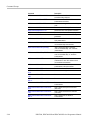
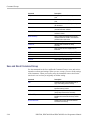
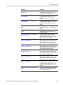
Limit Test Command Group
Use the commands in the Limit Test Command Group to perform limit testing
by selecting channel, math, or reference waveforms and comparing them against
a template waveform.
Command
Description
LIMit?
Returns all settings for the Limit commands
LIMit:BEEP
Causes the instrument to beep when the
waveform data exceeds the limits set in the
limit test
LIMit:COMpare
Resets the limit test comparison template
LIMit:COMpare:CH<x>
Sets or queries the template against which
to compare the waveform acquired from the
channel specified by x
LIMit:COMpare:MATH<x>
Sets or queries the template against which to
compare the math waveform specified by x
LIMit:COMpare:REF<x>
Sets or queries the template against which to
compare the reference waveform specified
by x
LIMit:EMail
Sets or queries whether an E-mail is
generated when the source waveform data
exceeds the limits specified for the limit test
LIMit:HARDCopy
Sets or queries whether a hard copy
operation is executed on the waveform when
any waveform data exceeds the limit set in
the limit test. LIMit:STATE must be set to ON
for the hard copy operation to execute
LIMit:HIGHLIGHTHits
Sets or queries whether violation highlighting
occurs when limit testing is active, and,
if the RESET argument is set, clears the
highlighting
LIMit:HIGHLIGHTHits:RESet
Resets the hits highlighting for limit testing
LIMit:LOCk
Sets or queries whether vertical scaling and
positioning affect both source and template
for template comparison pairs
LIMit:LOG
Sets or queries whether a log file is saved
when the source waveform data exceeds the
test limits
LIMit:SAVEWFM
Sets or queries whether the source waveform
is saved when the source waveform data
exceeds the test limits
LIMit:SAVEWFM:FILEName
Sets or queries the path where waveforms
or log files will be saved when the waveform
data exceeds the limits set by the limit test
DPO7000, DPO70000/B and DSA7000/B Series Programmer Manual
2-27
Command Groups
Command
Description
LIMit:SRQ
Sets or queries whether a Service Request
Interrupt (SRQ) is generated when the
waveform data falls outside of the test limits
LIMit:STATE
Sets limit testing on or off or queries whether
limit testing is in effect
LIMit:STATus?
Queries the state of limit testing
LIMit:STOPOnviolation
Sets or queries whether acquisitions are
stopped when the waveform data exceeds
the test limits
LIMit:TEMPlate:STORe
Saves the specified source waveform to the
specified reference or file name
LIMit:TEMPlate:TOLerance:HORizontal
Sets or queries the amount, in units of
horizontal divisions, by which the source
waveform is varied horizontally when
creating the destination waveform
LIMit:TEMPlate:TOLerance:VERTical
Sets or queries the amount, in units of
vertical divisions, by which the source
waveform is varied vertically when creating
the destination waveform
LIMit:TEMPlate:DESTination
Sets or queries destination reference
waveform that the limit template
LIMit:TEMPlate:SOUrce
Sets or queries the channel, math
waveform, or reference waveform that the
LIMit:TEMPlate:STORe command will use
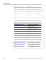
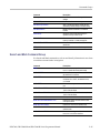
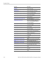
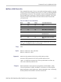
Low Speed Serial Trigger Command Group
DPO7000 Series only: Use the commands in the Low Speed Serial Trigger
Command Group to control serial triggering for the instrument. CAN trigger
commands are only available with the CAN option.
2-28
Command
Description
TRIGger:A:CAN:CONDition
Sets or returns the CAN condition
TRIGger:A:CAN:DATa:DIRection
Sets or queries the CAN trigger condition to
be valid on a READ, WRITE, or either
TRIGger:A:CAN:FORMat
Sets or queries the CAN data format
TRIGger:A:CAN:DATa:LEVel
Sets or queries the CAN Trigger threshold
for the CAN data source
TRIGger:A:CAN:DATa:SOUrce
Sets or queries the CAN data source
TRIGger:A:CAN:DATa:VALue
Sets or queries the binary data string used
for CAN Trigger if the trigger condition is ID
or IDANDDATA
TRIGger:A:CAN:FRAMEtype
Sets or queries the CAN trigger frame type
DPO7000, DPO70000/B and DSA7000/B Series Programmer Manual
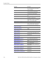
Command Groups
Command
Description
TRIGger:A:CAN:IDENTifier:MODe
Sets or queries the CAN trigger identifier
mode
TRIGger:A:CAN:IDENTifier:VALue
Sets or queries the binary address string
used for the CAN trigger if the trigger
condition is ID or IDANDDATA
TRIGger:A:CAN:PROBE
Sets or queries the probing method used to
probe the CAN signal
TRIGger:A:CAN:SPEed
Sets or queries the bit rate of the CAN
system
TRIGger:A:I2C:ADDRess:MODe
Sets or queries the I2C address mode to 7
or 10-bit
TRIGger:A:I2C:ADDRess:RWINClude
Sets or queries the I2C address mode to
include the read/write bit as an additional 8th
bit of the 7–bit address
TRIGger:A:I2C:ADDRess:TYPe
Sets or queries the I2C address type
TRIGger:A:I2C:ADDRess:VALue
Sets or queries the binary address string
used for the I2C trigger if the trigger condition
is ADDR or ADDRANDDATA
TRIGger:A:I2C:CLOCk:LEVel
Sets or queries the clock source for the I2C
Serial Trigger
TRIGger:A:I2C:CLOCk:SOUrce
Sets or queries the clock source for the I2C
Serial Trigger
TRIGger:A:I2C:CONDition
Sets or queries the trigger condition for the
I2C trigger
TRIGger:A:I2C:DATa:DIRection
Sets or queries the I2C trigger condition valid
on a READ, WRITE, or either
TRIGger:A:I2C:DATa:LEVel
Sets or queries the threshold level for the
I2C data source
TRIGger:A:I2C:DATa:SOUrce
Sets or queries the data source for the I2C
serial trigger
TRIGger:A:I2C:DATa:STARt
Sets or queries the data start byte
TRIGger:A:I2C:DATa:VALue
Sets or queries the binary data string used
for I2C triggering if the trigger condition is
DATA or ADDRANDDATA
TRIGger:A:I2C:FORMat
Sets or queries the display format for the I2C
data value
TRIGger:A:RS232:BAUd
Sets or queries the baud rate for RS232
triggering
TRIGger:A:RS232:DATa:LEVel
Sets or queries the threshold for the RS232
data source
TRIGger:A:RS232:DATa:SOUrce
Sets or queries the RS232 data source
TRIGger:A:RS232:DATa:VALue
Sets or queries the binary data string used
for RS232 triggering
DPO7000, DPO70000/B and DSA7000/B Series Programmer Manual
2-29
Command Groups
2-30
Command
Description
TRIGger:A:RS232:FORMat
Sets or queries the display format for the
RS232 data value
TRIGger:A:RS232:PARity
Sets or queries the state of the RS232 parity
bit
TRIGger:A:SERIAL:BITRate
Sets or queries the clock/data bit rate
TRIGger:A:SERIAL:CLOCk:LEVel
Sets or queries the serial trigger clock level
TRIGger:A:SERIAL:CLOCk:POLarity
Sets or queries the serial clock polarity
TRIGger:A:SERIAL:CLOCk:SOUrce
Sets or queries the serial data source
channel
TRIGger:A:SERIAL:CODe
Sets or queries the signal code
TRIGger:A:SERIAL:DATa:FORMat
Sets or queries how the Pattern string is
formatted
TRIGger:A:SERIAL:DATa:PATtern
Sets or queries the data pattern to allow up
to 64 bit serial patterns
TRIGger:A:SERIAL:DATa:PATtern:NRZ
Sets or queries the data pattern to allow up
to 64 bit serial patterns
TRIGger:A:SERIAL:DATa:PATtern:S8B10B
Sets or queries the data pattern to allow up
to 64 bit serial patterns
TRIGger:A:SERIAL:LOCKLen
Sets or queries the length in bits of the
repeating bit pattern for pattern lock trigger
TRIGger:A:SERIAL:LOCKOffset
Sets or queries the current bit offset into the
pattern lock trigger bit pattern
TRIGger:A:SERIAL:SOUrce
Sets or queries the serial data source
channel
TRIGger:A:SERIAL:STANdard
Sets or queries the standard that identifies
the code and bit rate
TRIGger:A:SERIAL:TRIGgeron
Sets or queries the trigger on a designated
arbitrary bit pattern or lock on a repeating
pattern of known length
TRIGger:A:SPI:CONDition
Sets or queries the trigger condition for SPI
triggering
TRIGger:A:SPI:DATa:MISO:ACTIVE
Sets or queries the SPI MISO polarity
TRIGger:A:SPI:DATa:MISO:LEVel
Sets or queries the threshold for the SPI
MISO data source
TRIGger:A:SPI:DATa:MISO:SOUrce
Sets or queries the MISO data source for the
SPI trigger
TRIGger:A:SPI:DATa:MISO:VALue
Sets or queries the binary data string used
for the SPI trigger if the trigger condition is
set to MISO or MISOMOSI
TRIGger:A:SPI:DATa:MOSI:ACTIVE
Sets or queries the SPI MOSI polarity
TRIGger:A:SPI:DATa:MOSI:LEVel
Sets or queries the threshold for the SPI
MOSI data source
DPO7000, DPO70000/B and DSA7000/B Series Programmer Manual
Command Groups
Command
Description
TRIGger:A:SPI:DATa:MOSI:SOUrce
Sets or queries the MOSI data source for the
SPI trigger
TRIGger:A:SPI:DATa:MOSI:VALue
Sets or queries the binary data string used
for the SPI trigger if the trigger condition is
set to MOSI or MISOMOSI
TRIGger:A:SPI:DATa:STARt
Sets or queries the nth data byte on the data
source after the signal on the enable slave
source switches to the polarity specified by
the Slave Select Polarity
TRIGger:A:SPI:FORMat
Sets or queries the SPI trigger data format
TRIGger:A:SPI:SCLK:ACTIVE
Sets or queries the SPI SCLK polarity
TRIGger:A:SPI:SCLK:LEVel
Sets or queries the threshold for the SPI
trigger SCLK
TRIGger:A:SPI:SCLK:SOUrce
Sets or queries the SPI SCLK source
TRIGger:A:SPI:SS:ACTIVE
Sets or queries the SPI trigger Slave Select
(SS) polarity
TRIGger:A:SPI:SS:LEVel
Sets or queries the threshold for the SPI
trigger Slave Select (SS) signal
TRIGger:A:SPI:SS:SOUrce
Sets or queries the SPI trigger Slave Select
(SS) source
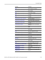
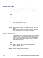
Mask Command Group
Use the commands in the Mask Command Group to compare incoming waveforms
against standard or user-defined telecommunications masks. Standard masks are
only available when option MTM is installed. Without option MTM, you need
to define your masks. When the instrument detects waveforms that fall inside or
outside of the mask limits, it can perform tasks such as generating hard copy,
saving the waveform, emitting a beep or an SRQ, stopping and waiting for your
input, sending an E-mail message with specified data, logging the time/date of the
acquired waveform, or some combination of these actions.
A mask is a set of polygonal regions on the screen. Every vertical line of the
screen intersects the polygon in zero, one, or two places, but never in more than
two places. (A vertical line that intersects a vertical mask border is counted.) You
have to break up more complicated polygons into two separate segments. Unlike
limit testing, the inside of a mask is the region where waveform data would
not normally fall. A telecommunications standard requires up to eight of these
segments. Pulse standards always have two segments. Standards with eye patterns
usually have three masks, but some have four.
DPO7000, DPO70000/B and DSA7000/B Series Programmer Manual
2-31
Command Groups
You use the commands in the Mask Command Group to do the following:
Specify the waveform source to test and the mask to use.
Specify whether to use, and the size of, mask margins, which allow you to
shrink or expand an existing set of polygons by a specified percentage.
Specify whether to display a readout of hits and the mask on screen. Options
also exist for auto fitting the incoming waveforms to match the mask you
choose.
Select industry-standard masks that support a variety of electrical and optical
communication standards (available only with option MTM).
Define and edit your own custom mask; create an entirely new mask, or use
a standard mask (option MTM only) as a starting reference, and edit it to
meet your needs.
Enable, disable, or reset the mask counts. Once you turn on mask counting, it
remains on until you explicitly turn it off.
Option MTM also provides communication trigger commands that you can use in
conjunction with the mask commands, such as TRIGger:A:TYPe Communication.
Refer to the Trigger Command Group.
2-32
Command
Description
MASK?
Returns the states of all settable mask
parameters
MASK:AUTOAdjust
Optimizes signal position within the mask to
minimize hits
MASK:AUTOAdjust:HDELTA
Sets or returns how far autofit searches
horizontally
MASK:AUTOAdjust:VDELTA
Sets or returns how far autofit searches
vertically
MASK:AUTOSet:AUTOAdjust
Controls what happens at the end of a mask
autoset. If ON, the horz/vert auto adjustment
is run ONCE to potentially improve the result
of mask autoset
MASK:AUTOSet:HPOS
Controls whether the algorithm will attempt to
change the horizontal position of the signal
while attempting to autoset
MASK:AUTOSet:HSCAle
Controls whether the algorithm will attempt to
change the horizontal scale while attempting
to autoset
MASK:AUTOSet:MODe
Controls whether an autoset will be
automatically done after a standard mask is
selected
DPO7000, DPO70000/B and DSA7000/B Series Programmer Manual
Command Groups
Command
Description
MASK:AUTOSet:OFFSETAdj
Sets autoset not to enforce the rule that,
for pulse standards, requires 0 V to be in a
certain place in the mask. Instead, autoset
will attempt to measure the DC offset in
the signal and use scope offset or position
controls to compensate for the DC offset in
the signal
MASK:AUTOSet:STANdard
Selects the standard mask in autoset
MASK:AUTOSet:TRIGger
Controls if a MASK:AUTOSet affects the
trigger level
MASK:AUTOSet:USER:ONE
Sets or returns the level 1 used by autoset
for user masks
MASK:AUTOSet:USER:TYPe
Sets or returns how autoset scales a mask
MASK:AUTOSet:USER:ZERo
Sets or returns the level 0 used by autoset
for user masks
MASK:AUTOSet:VPOS
Controls whether the autoset algorithm will
affect the vertical position (or offset) of the
signal while attempting to autoset
MASK:AUTOSet:VSCAle
Controls whether the autoset algorithm will
attempt to change the vertical scale while
attempting to autoset
MASK:COPy:USER
Copies the currently displayed mask to the
User mask
MASK:COUNt
Resets to zero the number of hits for all mask
segments on the specified source
MASK:COUNt:FAILURES?
Returns the number of pass/fail tests that
have failed
MASK:COUNt:HITS?
Returns the total number of mask hits on all
mask segments
MASK:COUNt:SEG<m>:HITS?
Returns the number of hits in mask segment
<m>
MASK:COUNt:STATE
Sets or returns the mask hits count state
MASK:COUNt:TESTS?
Returns the number of pass/fail tests that
have occurred
MASK:COUNt:TOTal?
Returns the sum of all hits in all mask
segments
MASK:COUNt:VIOLATIONS?
Returns the number of test violations that
have occurred in the current pass/fail test
MASK:COUNt:WAVEFORMS?
Returns the number of waveforms that
have been acquired and processed during
pass/fail testing
MASK:DISplay
Sets or returns whether the defined masks
are displayed on the screen
DPO7000, DPO70000/B and DSA7000/B Series Programmer Manual
2-33
Command Groups
2-34
Command
Description
MASK:FILTer
Sets or returns whether the selected optical
reference receiver mask filter is enabled
MASK:HIGHLIGHTHits
Sets or returns whether the hits in a mask
are highlighted in different colors than other
waveform data
MASK:INVert
Controls whether the mask is drawn inverted
MASK:LOCk
Sets or returns the mask lock to waveform
mode
MASK:MARgin:PERCent
Sets or queries the mask margin percentage
MASK:MARgin:STATE
Sets or returns the state of the mask margins
MASK:MASKPRE:AMPlitude
Sets or returns the current mask’s nominal
pulse amplitude in volts
MASK:MASKPRE:HSCAle
Sets or returns the nominal timing
resolution used to draw the current mask, in
time/division
MASK:MASKPRE:HTRIGPOS
Sets or returns the nominal trigger position
(pulse leading edge) used to draw the current
mask as a fraction of the display width
MASK:MASKPRE:PATTERNBITS
Sets or returns the number of bits used for
serial trigger for the current mask standard
MASK:MASKPRE:PRESAMPBITS
Sets or returns the number of bits before
the (isolated one) pulse leading edge in the
serial trigger pass/fail testing
MASK:MASKPRE:RECOrdlength
Sets or returns the nominal record length for
pulse mask testing
MASK:MASKPRE:TRIGTOSAMP
Sets or returns the time, in seconds, from the
(leading edge) trigger position to the pulse
bit sampling position
MASK:MASKPRE:VOFFSet
Sets or returns the nominal vertical offset,
in volts, used to vertically offset the input
channels
MASK:MASKPRE:VPOS
Sets or returns the nominal vertical position,
in divisions, used to vertically position the
input channels
MASK:MASKPRE:VSCAle
Sets or returns the nominal vertical scale, in
volts per division, used to vertically scale the
input channels
MASK:MASKPRE:WIDth
Sets or returns the nominal bit width in
seconds
MASK:POLarity
Sets or returns the input waveform polarity
for the pass/fail test
MASK:SEG<m>
Deletes the specified mask segment from
the Current mask
DPO7000, DPO70000/B and DSA7000/B Series Programmer Manual
Command Groups
Command
Description
MASK:SEG<m>:NR_Pt?
Returns the number of points that make up
the specified mask segment of the Current
mask
MASK:SEG<m>:POINTS
Sets or returns the X-Y user coordinates of
all points in the Current mask segment
MASK:SOUrce
Sets or reports which source will be
compared against the mask(s) when
counting is turned on
MASK:STANdard
Deletes the existing mask and sets the
selected standard mask
MASK:STOPOnviolation
Sets or returns the stop on violation setting
MASK:TESt:AUX:COMPLetion
Sets or returns the test:aux on pass/fail test
completion mode
MASK:TESt:AUX:FAILure
Sets or returns the test:aux status on
pass/fail test failure mode
MASK:TESt:BEEP:COMPLetion
Sets or returns the beep on pass/fail test
completion mode
MASK:TESt:BEEP:FAILure
Sets or returns the beep status on pass/fail
test failure mode
MASK:TESt:DELay
Sets or returns the amount of time, in
seconds, to wait after starting pass/fail
testing to evaluate waveforms
MASK:TESt:HARDCopy
Sets or returns the hard copy in pass/fail
failure mode
MASK:TESt:LOG:FAILure
Sets or returns the log status on pass/fail
test failure mode
MASK:TESt:REPeat
Sets or returns the repeat pass/fail test on
completion mode
MASK:TESt:SAMple
Sets or returns the minimum number of
waveform database (WfmDB) points the
instrument can acquire before it stops a
single sequence acquisition or stops running
a mask test
MASK:TESt:SAMple:THReshold
Sets or returns the minimum number of hits in
mask regions needed to cause the pass/fail
status to change from PASSING to FAILING
MASK:TESt:SAVEWFM
Sets or returns the save waveform to file on
failure setting
MASK:TESt:SAVEWFM:FILEName
Sets or returns the name of the directory and
file to use with the MASK:TESt:SAVEWFM
command
MASK:TESt:SRQ:COMPLetion
Sets or returns an SRQ on pass/fail test
completion mode
DPO7000, DPO70000/B and DSA7000/B Series Programmer Manual
2-35
Command Groups
2-36
Command
Description
MASK:TESt:SRQ:FAILure
Sets or returns the SRQ status on pass/fail
test failure mode
MASK:TESt:STATE
Sets or returns the state of mask pass/fail
testing
MASK:TESt:STATUS?
Returns the pass/fail test status
MASK:TESt:STOP:FAILure
Sets or returns the stop status on pass/fail
test failure mode
MASK:TESt:THReshold
Sets or returns the number of failed tested
waveforms needed in each pass/fail test to
cause the pass/fail status to change from
PASSING to FAILING
MASK:TESt:WAVEform
Sets or returns the number of waveforms to
test during pass/fail testing
MASK:USER:AMPlitude
Sets or returns the current mask’s nominal
pulse amplitude in volts
MASK:USER:BITRate
Sets or returns the user mask’s bit rate
MASK:USER:HSCAle
Sets or returns the nominal timing resolution
used to draw the mask, in time/division
MASK:USER:HTRIGPOS
Sets or returns the nominal trigger position
(pulse leading edge) used to draw the mask
as a fraction of the display width
MASK:USER:LABel
Sets or returns the label assigned to a user
mask
MASK:USER:PATTERNBITS
Sets or returns the number of bits used for
serial trigger for the User mask standard
MASK:USER:PRESAMPBITS
Sets or returns the number of bits before
the (isolated one) pulse leading edge in the
serial trigger pass/fail testing
MASK:USER:RECOrdlength
Sets or returns the nominal record length for
pulse mask testing
MASK:USER:SEG<m>
Deletes the specified mask segment from
the User mask
MASK:USER:SEG<m>:NR_Pt?
Returns the number of points that make up
the specified User mask segment
MASK:USER:SEG<m>:POINTS
Sets or returns the X-Y user coordinates of
all points in the specified User mask segment
MASK:USER:TRIGTOSAMP
Sets or returns the time, in seconds, from the
(leading edge) trigger position to the pulse
bit sampling position
MASK:USER:VOFFSet
Sets or returns the nominal vertical offset,
in volts, used to vertically offset the input
channels
DPO7000, DPO70000/B and DSA7000/B Series Programmer Manual
Command Groups
Command
Description
MASK:USER:VPOS
Sets or returns the nominal vertical position,
in divisions, used to vertically position the
input channels
MASK:USER:VSCAle
Sets or returns the nominal vertical scale, in
volts per division, used to vertically scale the
input channels
MASK:USER:WIDth
Sets or returns the nominal bit width in
seconds
RECAll:MASK
Recalls a stored mask as the User mask
SAVe:MASK
Saves the User mask to a mass storage file
Math Command Group
Use the commands in the Math Command Group to create and define math
waveforms. You can define and display up to four math waveforms simultaneously
on four channel models and up to two on two channel models. Use the available
math functions to define your math waveform.
The math waveform you create depends on sources listed in the math expression.
If you change these sources, the math waveforms you previously defined will be
affected.
Math expressions can be simple, containing no mathematical computation, such
as CH1, which specifies that a waveform shows the signal source of channel 1.
Math expressions can also be complex, consisting of 100 plus characters and
comprising many sources, functions, and operands.
The acquisition of a live waveform can stop for several reasons: You can turn off
the channel, stop the waveform (via Run/Stop from the Horiz/Acq menu), or stop
the trigger (via Run/Stop from the Trig menu). When you turn off the channel,
math continues and data is acquired but is not displayed. When you stop either the
waveform or the trigger, the math calculation stops, and the last math calculation
performed is displayed.
When a live waveform update or reference waveform is altered, math waveforms
containing those waveforms as sources are also updated to reflect the changes.
Also, sources must exist but do not need to be displayed to be used in and to
update math waveforms.
Command
Description
MATH<x>?
Returns the specified math waveform
settings
MATH<x>:DEFine
Sets or returns the math<x> waveform
definition for the specified waveform
MATH<x>:FILTer:MODe
Sets or returns the filter rise time parameter
(centered or shifted)
DPO7000, DPO70000/B and DSA7000/B Series Programmer Manual
2-37
Command Groups
2-38
Command
Description
MATH<x>:FILTer:RISetime
Sets or returns the filter rise time parameter
MATH<x>:LABel:NAMe
Sets or returns the label string used for
annotating the displayed math waveform
MATH<x>:LABel:XPOS
Sets or returns the X screen offset where the
math waveform label is displayed
MATH<x>:LABel:YPOS
Sets or returns the Y screen offset where the
math waveform label is displayed
MATH<x>:NUMAVg
Sets or returns the acquisition number at
which the averaging algorithm will begin
exponential averaging
MATH<x>:SPECTral?
Returns the specified math waveform
spectral setups
MATH<x>:SPECTral:CENTER
Sets or returns the center frequency of the
spectral analyzer output data span
MATH<x>:SPECTral:GATEPOS
Sets or returns the position of the center of
the gate
MATH<x>:SPECTral:GATEWIDTH
Sets or returns the gate width input to the
spectral analyzer
MATH<x>:SPECTral:LOCk
Sets or returns the state of the spectral
locking for the specified math waveform
MATH<x>:SPECTral:MAG
Sets or returns the units of the SpectralMag
function in the specified math string
MATH<x>:SPECTral:PHASE
Sets or returns the units of the SpectralPhase
function in the specified math string
MATH<x>:SPECTral:REFLevel
Sets or returns the vertical position of the
output data from the spectral analyzer
MATH<x>:SPECTral:REFLEVELOffset
Sets or returns the spectral reference level
offset used for calculating the dB value
MATH<x>:SPECTral:RESBw
Sets or returns the resolution bandwidth of
the spectral analyzer
MATH<x>:SPECTral:SPAN
Sets the top of the frequency span to a value
that is closest to the specified value
Or returns the specified math waveform’s
current frequency span value
MATH<x>:SPECTral:SUPPress
Sets or returns the phase suppression
threshold
MATH<x>:SPECTral:UNWRap
Enables or disables or returns the state of
the phase unwrap of the spectral analyzer
output data
MATH<x>:SPECTral:WINdow
Sets or returns the window function used
to multiply the input data to the spectral
analyzer
DPO7000, DPO70000/B and DSA7000/B Series Programmer Manual
Command Groups
Command
Description
MATH<x>:UNITString
Sets or returns the units used for the math
waveform; command overrides the default
unit string
MATH<x>:VERTical:POSition
Sets or returns the specified math waveform
vertical position
MATH<x>:VERTical:SCAle
Sets or returns the specified math waveform
vertical scale (per div)
MATHArbflt<x>:FILepath
Sets the file path for a file of filter coefficients
and reads the file
MATHArbflt<x>:READFile
Forces a reread of the filter file for the
specified arbitrary filter
MATHVAR?
Sets or returns all 8 numerical values you
can use within math expressions
MATHVAR:VAR<x>
Sets or returns a numerical value you can
use within math expressions
Measurement Command Group
Use the commands in the Measurement Command Group to control the automated
measurement system.
Up to eight automated measurements can be displayed on the screen. In the
commands, these measurement readouts are named MEAS<x>, where <x> can be
1 through 8.
In addition to the eight displayed measurements, the measurement commands let
you specify an additional measurement, IMMed. The immediate measurement
has no front panel equivalent. Immediate measurements are never displayed.
Because they are computed only when needed, immediate measurements slow the
waveform update rate less than displayed measurements.
Whether you use displayed or immediate measurements, use the VALue query to
obtain measurement results.
Measurement commands can set and query measurement parameters. You can
assign parameters, such as waveform sources and reference levels, differently
for each measurement.
Command
Description
MEASUrement?
Returns all measurement parameters
MEASUrement:ANNOTation:IMMEDSTAte
Sets or returns the state of immediate
measurement annotation
MEASUrement:ANNOTation:NUMX?
Returns the number of horizontal
measurement annotations being displayed
DPO7000, DPO70000/B and DSA7000/B Series Programmer Manual
2-39
Command Groups
2-40
Command
Description
MEASUrement:ANNOTation:NUMY?
Returns the number of vertical measurement
annotations being displayed
MEASUrement:ANNOTation:STATE
Sets or returns the state of visible
measurement annotations
MEASUrement:ANNOTation:TYPe
Sets or returns the type of annotations being
used
MEASUrement:ANNOTation:X<x>?
Returns the value of the specified annotation
MEASUrement:ANNOTation:Y<x>?
Returns the value of the specified annotation
MEASUrement:GATing
Sets or returns the measurement gating
MEASUrement:IMMed?
Returns all immediate measurement setup
parameters
MEASUrement:IMMed:DELay?
Returns information about the immediate
delay measurement
MEASUrement:IMMed:DELay:DIREction
Sets or returns the search direction to use
for immediate delay measurements
MEASUrement:IMMed:DELay:EDGE[1]
Sets or returns the slope of the edge
used for immediate delay “from” waveform
measurements
MEASUrement:IMMed:DELay:EDGE2
Sets or returns the slope of the edge
used for immediate delay “to” waveform
measurements
MEASUrement:IMMed:METHod
Specifies or queries the method used to
calculate the 0% and 100% reference level
for immediate measurements
MEASUrement:IMMed:NOISe
Sets or returns the location of the noise
measurement on the eye waveform
MEASUrement:IMMed:REFLevel?
Returns the reference levels
MEASUrement:IMMed:REFLevel:ABSolute:
HIGH
Sets or returns the high reference level
MEASUrement:IMMed:REFLevel:ABSolute:
LOW
Sets or returns the low reference level
MEASUrement:IMMed:REFLevel:ABSolute:
MID<x>
Sets or returns the middle reference levels
MEASUrement:IMMed:REFLevel:METHod
Sets or returns the method used to calculate
measurements
MEASUrement:IMMed:REFLevel:PERCent:
HIGH
Sets or returns the top level for rise time
(90% level)
MEASUrement:IMMed:REFLevel:PERCent:
LOW
Sets or returns the low level for rise time
(10% level)
MEASUrement:IMMed:REFLevel:PERCent:
MID<x>
Sets or returns the mid levels for
measurements
DPO7000, DPO70000/B and DSA7000/B Series Programmer Manual
Command Groups
Command
Description
MEASUrement:IMMed:SOUrce<x>
Sets or returns the source to measure “to”
or “from” for phase or delay immediate
measurements
MEASUrement:IMMed:SOUrce<x>:SIGType
Sets or returns the type of input signal used
for the specified measurement source
MEASUrement:IMMed:TYPe
Sets or returns the type of the immediate
measurement
MEASUrement:IMMed:UNIts?
Returns the units of the immediate
measurement
MEASUrement:IMMed:VALue?
Returns the value of the immediate
measurement
MEASUrement:MEAS<x>?
Returns all measurement parameters for the
displayed measurement
MEASUrement:MEAS<x>:COUNt?
Returns the number of values accumulated
since the last statistical reset
MEASUrement:MEAS<x>:DELay?
Returns the delay measurement parameters
for specified measurement
MEASUrement:MEAS<x>:DELay:DIREction
Sets or returns the search direction to use
for delay measurements
MEASUrement:MEAS<x>:DELay:EDGE<x>
Sets or returns the slope of the edge
to use for delay “from” or “to” waveform
measurements
MEASUrement:MEAS<x>:MAXimum?
Returns the maximum value found since the
last statistical reset
MEASUrement:MEAS<x>:MEAN?
Returns the mean value accumulated since
the last statistical reset
MEASUrement:MEAS<x>:METHod
Sets or returns the method used to calculate
the 0% and 100% reference level
MEASUrement:MEAS<x>:MINImum?
Returns the minimum value found since the
last statistical reset
MEASUrement:MEAS<x>:NOISe
Sets or returns the location of the noise
measurement on the eye waveform for
MEAS<x>
MEASUrement:MEAS<x>:REFLevel?
Returns the reference levels
MEASUrement:MEAS<x>:REFLevel:
ABSolute:HIGH
Sets or returns the top level for rise time
(90% level)
MEASUrement:MEAS<x>:REFLevel:
ABSolute:LOW
Sets or returns the low level for rise time
(10%)
MEASUrement:MEAS<x>:REFLevel:
ABSolute:MID<x>
Sets or returns the mid1 or mid2 level for
measurements
MEASUrement:MEAS<x>:REFLevel:
METHod
Sets or returns the reference level units used
for measurement calculations
MEASUrement:MEAS<x>:REFLevel:
PERCent:HIGH
Sets or returns the top level for rise time
(90% level)
DPO7000, DPO70000/B and DSA7000/B Series Programmer Manual
2-41
Command Groups
2-42
Command
Description
MEASUrement:MEAS<x>:REFLevel:
PERCent:LOW
Sets or returns the low level for rise time
(10% level)
MEASUrement:MEAS<x>:REFLevel:
PERCent:MID<x>
Sets or returns the mid1 or mid2 level for
delay measurements
MEASUrement:MEAS<x>:SOUrce<x>
Sets or returns the source to measure “from”
or “to” for phase or delay measurements
MEASUrement:MEAS<x>:SOUrce<x>:
SIGType
Sets or returns the type of input signal used
for the specified measurement source for the
specified measurement slot
MEASUrement:MEAS<x>:STATE
Sets or returns whether the specified
measurement slot is computed and
displayed
MEASUrement:MEAS<x>:STDdev?
Returns the standard deviation of values
accumulated since the last statistical reset
MEASUrement:MEAS<x>:TYPe
Sets or returns the measurement<x> type
MEASUrement:MEAS<x>:UNIts?
Returns measurement<x> units
MEASUrement:MEAS<x>:VALue?
Returns the value of measurement<x>
MEASUrement:METHod
Sets or returns the method used for
calculating reference levels
MEASUrement:NOISe
Sets or returns the location of the noise
measurement on the eye waveform
MEASUrement:REFLevel:ABSolute:HIGH
Sets or returns the top reference level for
rise time
MEASUrement:REFLevel:ABSolute:LOW
Sets or returns the low reference level for
rise time
MEASUrement:REFLevel:ABSolute:MID<x>
Sets or returns the mid1 or mid2 reference
level for measurements
MEASUrement:REFLevel:METHod
Sets or returns the method for assigning high
and low reference levels
MEASUrement:REFLevel:PERCent:HIGH
Sets or returns the top reference percent
level for rise time
MEASUrement:REFLevel:PERCent:LOW
Sets or returns the low reference percent
level for rise time
MEASUrement:REFLevel:PERCent:MID<x>
Sets or returns the mid1 or mid 2 reference
percent level for waveform measurements
MEASUrement:SOUrce<x>:SIGType
Sets or returns the type of input signal used
for the specified measurement source
MEASUrement:STATIstics:COUNt
Clears existing measurement statistics from
memory
DPO7000, DPO70000/B and DSA7000/B Series Programmer Manual
Command Groups
Command
Description
MEASUrement:STATIstics:MODe
Turns measurement statistics on or off
and sets or returns which pair of statistical
accumulations is displayed
MEASUrement:STATIstics:WEIghting
Sets or returns the ’time constant’ for
mean and standard deviation statistical
accumulations
Miscellaneous Command Group
Miscellaneous commands do not fit into other categories.
Several commands and queries are common to all 488.2-1987 devices on the
GPIB bus. The 488.2-1987 standard defines these commands. The common
commands begin with an asterisk (*) character.
Command
Description
AUXout?
Returns the auxiliary out setup
AUXout:EDGE
Sets or returns the direction in which the
trigger output signal will transition when a
trigger occurs
AUXout:SOUrce
Sets or returns the trigger source at the BNC
connection
AUTOSet
Sets the vertical, horizontal, and trigger
controls of the instrument to automatically
acquire and display the selected waveform
BELl
In previous models, this command sounded
the audio indicator. Provided for backward
compatibility
CMDBatch
Turns command batching on or off
Or returns the state of command batching
DATE
Sets or returns the date that the instrument
can display
*DDT
Sets or returns the commands that will be
executed by the group execute trigger
HEADer
Sets or returns the Response Header Enable
State
HDR
Sets or returns the Response Header Enable
State
ID?
Returns identifying information about the
instrument and its firmware
*IDN?
Returns the instrument identification code
LOCk
Sets or returns the front panel lock state
*LRN?
Returns a listing of instrument settings
DPO7000, DPO70000/B and DSA7000/B Series Programmer Manual
2-43
Command Groups
Command
Description
NEWpass
Changes the password for user protected
data
PASSWord
Provides access for changing user protected
data
REM
Specifies a comment, which is ignored by
the instrument
ROSc:SOUrce
Sets or queries the selected source for the
time base reference oscillator
ROSc:STATE?
Returns whether the time base reference
oscillator is locked
ROSc:TRACking
Sets or queries the selected source for the
time base reference oscillator. The reference
oscillator locks to this source
SET?
Returns a listing of instrument settings
TEKSecure
Initializes both waveform and setup
memories
TIME
Sets or returns the time displayed by the
instrument
*TRG
Performs the group execute trigger (GET)
*TST?
Tests the GPIB interface and returns status
UNLock
Unlocks front panel
VERBose
Sets or returns the verbose state
Save and Recall Command Group
Use the commands in the Save and Recall Command Group to store and retrieve
internal waveforms and settings. When you save a setup, you save all the settings
of the instrument. When you recall a setup, the instrument restores itself to the
state that it was in when you originally saved that setting.
2-44
Command
Description
*RCL
Restores the state of the instrument from a
copy of the setting stored in memory
*SAV
Stores the current instrument state to a
specified memory location
*SDS
Changes the specified setup to reference the
factory setup instead of the user setup
DELEte:SETUp
Removes stored setups from memory and
initializes the location with the factory default
setups
DELEte:WAVEform
Deletes (one or all of) the stored reference
waveforms from memory
DPO7000, DPO70000/B and DSA7000/B Series Programmer Manual
Command Groups
Command
Description
FACtory
Resets the instrument to factory default
settings
RECAll:SETUp
Recalls saved instrument settings
RECAll:SETUp:DESKew
Sets or queries the deskew values that are
affected by a default setup or a recalled setup
RECAll:WAVEform
Recalls a stored waveform to a reference
location
SAVe:SETUp
Saves the current front panel setup to a
specified memory location or file
SAVe:WAVEform
Saves a waveform to one of four reference
memory locations or a mass storage file
SAVe:WAVEform:FILEFormat
Sets or returns the format for saved
waveforms
SETUp:NAMe
Sets or returns the user-defined setup label
Search and Mark Command Group
Use Search and Mark commands to seek out and identify information in waveform
records that warrant further investigation.
Command
Description
MARK
Moves to the next or previous reference
mark, or queries the current mark setup
MARK:CREATE
Creates a mark on a specified waveform or
all waveforms in a column
MARK:DELEte
Deletes a mark on a particular waveform, all
waveforms in a column, the selected mark,
or all marks
MARK:FREE?
Returns how many marks are available for
use
MARK:SELected:END?
Returns the end of the selected mark, 0 to
100% of the waveform
MARK:SELected:FOCUS?
Returns the focus of the selected mark, 0 to
100% of the waveform
MARK:SELected:LABel
Set or queries the label for the selected mark
MARK:SELected:MARKSINCOLumn?
Returns the number of marks in the current
zoom pixel column
MARK:SELected:OWNer?
Returns the owner of the selected mark
MARK:SELected:SOURCE?
Sets or returns the source waveform for the
selected mark
MARK:SELected:STARt?
Returns the starting point of the selected
mark, 0 to 100% of the waveform
DPO7000, DPO70000/B and DSA7000/B Series Programmer Manual
2-45
Command Groups
2-46
Command
Description
MARK:SELected:STATe
Returns the on or off state of the selected
mark. The selected mark is at or near the
center of the display
MARK:SELected:ZOOm:POSition?
Returns the position of the selected mark, 0
to 100% of the zoom overview window
MARK:SELected:ZOOm:SCAle?
Returns the scale of the selected mark, 0 to
100% of the zoom overview window
MARK:TOTal?
Returns how many marks are currently in
use
SEARCH:SEARCH<x>
Converts the specified search marks to the
user marks. <x> can be 1 to 8
SEARCH:SEARCH<x>:COPy
Copies the search criteria to the trigger, the
trigger criteria to a search, or copy search to
search. <x> is the search number
SEARCH:SEARCH<x>:STATE
Selects which search is selected
SEARCH:SEARCH<x>:TOTAL?
Returns the total number of matches for the
search. The total number of matches may
be more than the number of marks placed
SEARCH:SEARCH<x>:TRIGger:A:
DDRMemory:AUTOBitrate
Sets or queries the auto bit rate setting
SEARCH:SEARCH<x>:TRIGger:A:
DDRMemory:AUTOReflevel
Sets or queries the auto reference levels
setting
SEARCH:SEARCH<x>:TRIGger:A:
DDRMemory:BITRate
Sets or queries the DDR memory bit rate
SEARCH:SEARCH<x>:TRIGger:A:
DDRMemory:CSActive
Sets or queries whether the expected
chip-select will be an active HIGH or LOW
SEARCH:SEARCH<x>:TRIGger:A:
DDRMemory:CSLevel
Sets or queries the DDR memory search
chip-select level
SEARCH:SEARCH<x>:TRIGger:A:
DDRMemory:CSMode
Sets or queries the chip-select mode
SEARCH:SEARCH<x>:TRIGger:A:
DDRMemory:CSSource
Sets or queries the chip select source
SEARCH:SEARCH<x>:TRIGger:A:
DDRMemory:DATASource
Sets or queries the DDR memory data
source
SEARCH:SEARCH<x>:TRIGger:A:
DDRMemory:HYSterisis
Sets or queries the hysterisis percent for
DDR memory searches
SEARCH:SEARCH<x>:TRIGger:A:
DDRMemory:REFLevel:DATA:HIGH
Sets or queries the value of the data HIGH
reference level
SEARCH:SEARCH<x>:TRIGger:A:
DDRMemory:REFLevel:DATA:LOW
Sets or queries the value of the data LOW
reference level
SEARCH:SEARCH<x>:TRIGger:A:
DDRMemory:REFLevel:DATA:MID
Sets or queries the value of the data MID
reference level
SEARCH:SEARCH<x>:TRIGger:A:
DDRMemory:REFLevel:STROBE:HIGH
Sets or queries the value of the strobe HIGH
reference level
DPO7000, DPO70000/B and DSA7000/B Series Programmer Manual
Command Groups
Command
Description
SEARCH:SEARCH<x>:TRIGger:A:
DDRMemory:REFLevel:STROBE:LOW
Sets or queries the value of the strobe LOW
reference level
SEARCH:SEARCH<x>:TRIGger:A:
DDRMemory:REFLevel:STROBE:MID
Sets or queries the value of the strobe MID
reference level
SEARCH:SEARCH<x>:TRIGger:A:
DDRMemory:STANdard
Sets or queries the DDR standard type for a
DDR Memory analysis search
SEARCH:SEARCH<x>:TRIGger:A:
DDRMemory:STROBEsource
Sets or queries the strobe source for a DDR
Memory analysis search
SEARCH:SEARCH<x>:TRIGger:A:EDGE:
SLOpe:CH<x>
Sets or returns the slope for an edge trigger
search to determine where to place a mark.
<x> is the search number or the channel
number
SEARCH:SEARCH<x>:TRIGger:A:EDGE:
SLOpe:MATH<x>
Sets or returns the slope for an edge trigger
search to determine where to place a mark.
<x> is the search number or the math
waveform number
SEARCH:SEARCH<x>:TRIGger:A:EDGE:
SLOpe:REF<x>
Sets or returns the slope for an edge trigger
search to determine where to place a mark.
<x> is the search number or the reference
waveform number
SEARCH:SEARCH<x>:TRIGger:A:EDGE:
SOUrce
Sets or returns the source waveform for an
edge trigger search to determine where to
place a mark. <x> is the search number
SEARCH:SEARCH<x>:TRIGger:A:GLItch:
POLarity:CH<x>
Sets or returns the polarity for a glitch trigger
search to determine where to place a mark.
<x> is the search number or channel number
SEARCH:SEARCH<x>:TRIGger:A:GLItch:
POLarity:MATH<x>
Sets or returns the polarity for a glitch trigger
search to determine where to place a mark.
<x> is the search number or math waveform
number
SEARCH:SEARCH<x>:TRIGger:A:GLItch:
POLarity:REF<x>
Sets or returns the polarity for a glitch trigger
search to determine where to place a mark.
<x> is the search number or reference
waveform number
SEARCH:SEARCH<x>:TRIGger:A:GLItch:
TRIGIF
Sets or returns the accept or reject state for
a glitch trigger search to determine where to
place a mark. <x> is the search number
SEARCH:SEARCH<x>:TRIGger:A:GLItch:
WIDth
Sets or returns the glitch width for a glitch
trigger search to determine where to place a
mark. <x> is the search number
SEARCH:SEARCH<x>:TRIGger:A:LEVel:
CH<x>
Sets or returns the level for an edge trigger
search to determine where to place a
mark. <x> is the search number or the
channel number. Each channel can have an
independent level
DPO7000, DPO70000/B and DSA7000/B Series Programmer Manual
2-47
Command Groups
2-48
Command
Description
SEARCH:SEARCH<x>:TRIGger:A:LEVel:
MATH<x>
Sets or returns the math waveform level for
an edge trigger search to determine where
to place a mark. <x> is the search number
or math waveform number
SEARCH:SEARCH<x>:TRIGger:A:LEVel:
REF<x>
Sets or returns the specified reference
waveform level for a trigger search
to determine where to place a mark.
SEARCH<x> is the search number and
REF<x> is the reference channel number
SEARCH:SEARCH<x>:TRIGger:A:LOGIc:
FUNCtion
Sets or returns the logic operator for a
pattern or state trigger search to determine
where to place a mark. <x> is the search
number
SEARCH:SEARCH<x>:TRIGger:A:LOGIc:
INPut:CH<x>
Sets or returns the Boolean logic criteria for
a pattern or state trigger search to determine
where to place a mark. <x> is the search
number or the channel number
SEARCH:SEARCH<x>:TRIGger:A:LOGIc:
INPut:MATH<x>
Sets or returns the Boolean logic criteria for
a pattern or state trigger search to determine
where to place a mark. <x> is the search
number or the math waveform number
SEARCH:SEARCH<x>:TRIGger:A:LOGIc:
INPut:REF<x>
Sets or returns the Boolean logic criteria for
a pattern or state trigger search to determine
where to place a mark. <x> is the search
number or the reference channel number
SEARCH:SEARCH<x>:TRIGger:A:LOGIc:
THReshold:CH<x>
Sets or returns the channel threshold
level for a pattern or state trigger search
to determine where to place a mark.
SEARCH<x> is the search number and
CH<x> is the channel number
SEARCH:SEARCH<x>:TRIGger:A:LOGIc:
THReshold:MATH<x>
Sets or returns the math waveform threshold
level for a pattern or state trigger search to
determine where to place a mark. <x> is
the search number or the Math waveform
number
SEARCH:SEARCH<x>:TRIGger:A:LOGIc:
THReshold:REF<x>
Sets or returns the reference waveform
threshold level for a pattern or state trigger
search to determine where to place a mark.
<x> is the search number or the reference
waveform number
SEARCH:SEARCH<x>:TRIGger:A:PATtern:
WHEn
Sets or queries the pattern trigger pattern
test that determines where to place a mark.
<x> is the search number
SEARCH:SEARCH<x>:TRIGger:A:PATtern:
WHEn:LESSLimit
Sets or queries the time the pattern trigger
less limit test uses to determines where to
place a mark. <x> is the search number
DPO7000, DPO70000/B and DSA7000/B Series Programmer Manual
Command Groups
Command
Description
SEARCH:SEARCH<x>:TRIGger:A:PATtern:
WHEn:MORELimit
Sets or queries the time the pattern trigger
more limit test uses to determines where to
place a mark. <x> is the search number
SEARCH:SEARCH<x>:TRIGger:A:PULse:
SOUrce
Sets or returns the source waveform for a
pulse trigger search to determine where to
place a mark. <x> is the search number.
This is the source for Glitch, Width, Runt,
Timeout or Window searches.
SEARCH:SEARCH<x>:TRIGger:A:RUNT:
POLarity:CH<x>
Sets or returns the polarity setting for a runt
trigger search to determine where to place a
mark. <x> is the search number or channel
number
SEARCH:SEARCH<x>:TRIGger:A:RUNT:
POLarity:MATH<x>
Sets or returns the polarity setting for a runt
trigger search to determine where to place
a mark. <x> is the search number or math
waveform number
SEARCH:SEARCH<x>:TRIGger:A:RUNT:
POLarity:REF<x>
Sets or returns the polarity setting for a runt
trigger search to determine where to place a
mark. <x> is the search number or reference
waveform number
SEARCH:SEARCH<x>:TRIGger:A:RUNT:
THReshold:HIGH:CH<x>
Sets or returns the channel threshold HIGH
level for a runt trigger search to determine
where to place a mark. <x> is the search
number or the channel number
SEARCH:SEARCH<x>:TRIGger:A:RUNT:
THReshold:HIGH:MATH<x>
Sets or returns the math waveform threshold
HIGH level for a runt trigger search to
determine where to place a mark. <x> is
the search number or the math waveform
number
SEARCH:SEARCH<x>:TRIGger:A:RUNT:
THReshold:HIGH:REF<x>
Sets or returns the reference waveform
threshold HIGH level for a runt trigger
search to determine where to place a mark.
<x> is the search number or the reference
waveform number
SEARCH:SEARCH<x>:TRIGger:A:RUNT:
THReshold:LOW:CH<x>
Sets or returns the channel threshold LOW
level for a runt trigger search to determine
where to place a mark. <x> is the search
number or the channel number
SEARCH:SEARCH<x>:TRIGger:A:RUNT:
THReshold:LOW:MATH<x>
Sets or returns the math waveform threshold
LOW level for a runt trigger search to
determine where to place a mark. <x> is
the search number or the math waveform
number
DPO7000, DPO70000/B and DSA7000/B Series Programmer Manual
2-49
Command Groups
2-50
Command
Description
SEARCH:SEARCH<x>:TRIGger:A:RUNT:
THReshold:LOW:REF<x>
Sets or returns the reference waveform
threshold LOW level for a runt trigger search
to determine where to place a mark. <x>
is the search number or the reference
waveform number
SEARCH:SEARCH<x>:TRIGger:A:RUNT:
WHEn
Sets or returns the condition setting for a
runt trigger search to determine where to
place a mark. <x> is the search number
SEARCH:SEARCH<x>:TRIGger:A:RUNT:
WIDth
Sets or returns the width setting for a runt
trigger search to determine where to place a
mark. <x> is the search number
SEARCH:SEARCH<x>:TRIGger:A:SETHold:
CLOCk:EDGE
Sets or returns the clock slope setting for a
setup/hold trigger search to determine where
to place a mark. <x> is the search number
SEARCH:SEARCH<x>:TRIGger:A:SETHold:
CLOCk:SOUrce
Sets or returns the clock source setting for a
setup/hold trigger search to determine where
to place a mark. <x> is the search number
SEARCH:SEARCH<x>:TRIGger:A:SETHold:
CLOCk:THReshold:CH<x>
Sets or returns the clock threshold setting
for a setup/hold trigger search to determine
where to place a mark. <x> is the search
number or channel number
SEARCH:SEARCH<x>:TRIGger:A:SETHold:
CLOCk:THReshold:MATH<x>
Sets or returns the clock threshold setting
for a setup/hold trigger search to determine
where to place a mark. <x> is the search
number or math waveform number
SEARCH:SEARCH<x>:TRIGger:A:SETHold:
CLOCk:THReshold:REF<x>
Sets or returns the clock threshold setting
for a setup/hold trigger search to determine
where to place a mark. <x> is the search
number or reference waveform number
SEARCH:SEARCH<x>:TRIGger:A:SETHold:
DATa:SOUrce
Sets or returns the data source setting for a
setup/hold trigger search to determine where
to place a mark. <x> is the search number
SEARCH:SEARCH<x>:TRIGger:A:SETHold:
DATa:THReshold:CH<x>
Sets or returns the data threshold setting
for a setup/hold trigger search to determine
where to place a mark. <x> is the search
number or channel number
SEARCH:SEARCH<x>:TRIGger:A:SETHold:
DATa:THReshold:MATH<x>
Sets or returns the data threshold setting
for a setup/hold trigger search to determine
where to place a mark. <x> is the search
number or math waveform number
SEARCH:SEARCH<x>:TRIGger:A:SETHold:
DATa:THReshold:REF<x>
Sets or returns the threshold high voltage
level setting for a transition trigger search
to determine where to place a mark. <x> is
the search number or reference waveform
number
DPO7000, DPO70000/B and DSA7000/B Series Programmer Manual
Command Groups
Command
Description
SEARCH:SEARCH<x>:TRIGger:A:SETHold:
HOLDTime
Sets or returns the hold time setting for a
setup/hold trigger search to determine where
to place a mark. <x> is the search number
SEARCH:SEARCH<x>:TRIGger:A:SETHold:
SETTime
Sets or returns the setup time setting for a
setup/hold trigger search to determine where
to place a mark. <x> is the search number
SEARCH:SEARCH<x>:TRIGger:A:STATE:
CLOCk:EDGE
Sets or returns the clock slope setting for a
state trigger search to determine where to
place a mark. <x> is the search number
SEARCH:SEARCH<x>:TRIGger:A:STATE:
CLOCk:SOUrce
Sets or returns the clock source of the
twelve waveforms for a state trigger search
to determine where to place a mark. <x> is
the search number. The hardware trigger is
always on the channel CH4
SEARCH:SEARCH<x>:TRIGger:A:STATE:
WHEn
Sets or queries the state trigger search to
determine where to place a mark. <x> is
the search number
SEARCH:SEARCH<x>:TRIGger:A:TIMEOut:
POLarity:CH<x>
Sets or returns the polarity for a timeout
trigger search to determine where to place a
mark. <x> is the search number or channel
number
SEARCH:SEARCH<x>:TRIGger:A:TIMEOut:
POLarity:MATH<x>
Sets or returns the polarity for a timeout
trigger search to determine where to place
a mark. <x> is the search number or math
waveform number
SEARCH:SEARCH<x>:TRIGger:A:TIMEOut:
POLarity:REF<x>
Sets or returns the polarity for a timeout
trigger search to determine where to place a
mark. <x> is the search number or reference
waveform number
SEARCH:SEARCH<x>:TRIGger:A:TIMEOut:
TIMe
Sets or returns the time setting for a timeout
trigger search to determine where to place a
mark. <x> is the search number
SEARCH:SEARCH<x>:TRIGger:A:
TRANsition:DELTATime
Sets or returns the transition time setting
for a transition trigger search to determine
where to place a mark.<x> is the search
number
SEARCH:SEARCH<x>:TRIGger:A:
TRANsition:POLarity:CH<x>
Sets or returns the polarity setting for a
transition trigger search to determine where
to place a mark. <x> is the search number
or channel number
SEARCH:SEARCH<x>:TRIGger:A:
TRANsition:POLarity:MATH<x>
Sets or returns the polarity setting for a
transition trigger search to determine where
to place a mark. <x> is the search number
or math waveform number
DPO7000, DPO70000/B and DSA7000/B Series Programmer Manual
2-51
Command Groups
Command
Description
SEARCH:SEARCH<x>:TRIGger:A:
TRANsition:POLarity:REF<x>
Sets or returns the polarity setting for a
transition trigger search to determine where
to place a mark. <x> is the search number
or reference waveform number
SEARCH:SEARCH<x>:TRIGger:A:
TRANsition:THReshold:HIGH:CH<x>
Sets or returns the threshold high voltage
level setting for a transition trigger search to
determine where to place a mark. <x> is the
search number or channel number
SEARCH:SEARCH<x>:TRIGger:A:
TRANsition:THReshold:HIGH:MATH<x>
Sets or returns the threshold high voltage
level setting for a transition trigger search to
determine where to place a mark. <x> is the
search number or math waveform number
SEARCH:SEARCH<x>:TRIGger:A:
TRANsition:THReshold:HIGH:REF<x>
Sets or returns the threshold high voltage
level setting for a transition trigger search
to determine where to place a mark. <x> is
the search number or reference waveform
number
SEARCH:SEARCH<x>:TRIGger:A:
TRANsition:THReshold:LOW:CH<x>
Sets or returns the threshold low voltage
level setting for a transition trigger search to
determine where to place a mark. <x> is the
search number or channel number
SEARCH:SEARCH<x>:TRIGger:A:
TRANsition:THReshold:LOW:MATH<x>
Sets or returns the threshold low voltage
level setting for a transition trigger search to
determine where to place a mark. <x> is the
search number or math waveform number
SEARCH:SEARCH<x>:TRIGger:A:
TRANsition:THReshold:LOW:REF<x>
Sets or returns the threshold low voltage
level setting for a transition trigger search
to determine where to place a mark. <x> is
the search number or reference waveform
number
SEARCH:SEARCH<x>:TRIGger:A:
TRANsition:WHEn
Sets or returns the condition setting for a
transition trigger search to determine where
to place a mark. <x> is the search number
SEARCH:SEARCH<x>:TRIGger:A:TYPe
Sets or returns the trigger type setting for a
search to determine where to place a mark.
<x> is the search number
NOTE. Except EDGE all other
options must be purchased.
2-52
SEARCH:SEARCH<x>:TRIGger:A:WIDth:
HIGHLimit
Sets or returns the upper time limit setting
for a width search to determine where to
place a mark. <x> is the search number
SEARCH:SEARCH<x>:TRIGger:A:WIDth:
LOWLimit
Sets or returns the lower time limit setting for
a width search to determine where to place
a mark. <x> is the search number
DPO7000, DPO70000/B and DSA7000/B Series Programmer Manual
Command Groups
Command
Description
SEARCH:SEARCH<x>:TRIGger:A:WIDth:
POLarity:CH<x>
Sets or returns the polarity for a width search
to determine where to place a mark. <x> is
the search number or channel number
SEARCH:SEARCH<x>:TRIGger:A:WIDth:
POLarity:MATH<x>
Sets or returns the polarity for a width search
to determine where to place a mark. <x>
is the search number or math waveform
number
SEARCH:SEARCH<x>:TRIGger:A:WIDth:
POLarity:REF<x>
Sets or returns the polarity for a width search
to determine where to place a mark. <x> is
the search number or reference waveform
number
SEARCH:SEARCH<x>:TRIGger:A:WIDth:
WHEn
Sets or queries the width search to determine
where to place a mark. <x> is the search
number
SEARCH:SEARCH<x>:TRIGger:A:WINdow:
EVENT
Sets or queries the window search to
determine where to place a mark. <x> is
the search number
SEARCH:SEARCH<x>:TRIGger:A:WINdow:
THReshold:HIGH:CH<x>
Sets or returns the channel waveform
threshold HIGH level for a window search to
determine where to place a mark. <x> is the
search number or channel number
SEARCH:SEARCH<x>:TRIGger:A:WINdow:
THReshold:HIGH:MATH<x>
Sets or returns the channel waveform
threshold HIGH level for a window search to
determine where to place a mark. <x> is the
search number or math waveform number
SEARCH:SEARCH<x>:TRIGger:A:WINdow:
THReshold:HIGH:REF<x>
Sets or returns the channel waveform
threshold HIGH level for a window search to
determine where to place a mark. <x> is the
search number or reference number
SEARCH:SEARCH<x>:TRIGger:A:WINdow:
THReshold:LOW:CH<x>
Sets or returns the channel waveform
threshold LOW level for a window search to
determine where to place a mark. <x> is the
search number or channel number
SEARCH:SEARCH<x>:TRIGger:A:WINdow:
THReshold:LOW:MATH<x>
Sets or returns the channel waveform
threshold LOW level for a window search to
determine where to place a mark. <x> is the
search number or math waveform number
SEARCH:SEARCH<x>:TRIGger:A:WINdow:
THReshold:LOW:REF<x>
Sets or returns the channel waveform
threshold LOW level for a window search
to determine where to place a mark. <x> is
the search number or reference waveform
number
SEARCH:SEARCH<x>:TRIGger:A:WINdow:
WIDth
Sets or returns the width setting for a window
search to determine where to place a mark.
<x> is the search number
DPO7000, DPO70000/B and DSA7000/B Series Programmer Manual
2-53
Command Groups
Command
Description
SEARCH:STOP
Sets or queries the stop of acquisitions when
a search finds an event
SEARCH:SEARCH<x>:TRIGger:A:
DDRMemory:MARgin
Sets or queries the termination logic margin
for back-to-back writes
SEARCH:SEARCH<x>:TRIGger:A:
DDRMemory:MAXCas
Sets or queries the maximum distance, in
clock periods, to the left of the start of the
mark where the instrument looks for the
chip-select pulse
SEARCH:SEARCH<x>:TRIGger:A:
DDRMemory:MINCas
Sets or queries the minimum distance, in
clock periods, to the left of the start of the
mark where the instrument looks for the
chip-select pulse
Status and Error Command Group
Use the commands in the Status and Error command Group to determine the
status of the instrument and control events.
Several commands and queries used with the instrument are common to all
devices on the GPIB bus. The IEEE Std 488.2-1987 defines these commands and
queries. The common commands begin with an asterisk (*) character.
2-54
Command
Description
*CLS
Clears status
*ESE
Sets or returns the bits in the Event Status
Enable Register
*ESR?
Returns the contents of the Standard Event
Status Register
*OPC
Generates the operation complete message
in the standard event status register when all
pending operations are finished
Or returns “1” when all current operations
are finished
*OPT?
Returns a list of options installed in the
instrument
*PSC
Sets or returns the power on status flag
*PUD
Sets or returns a string of protected user data
*RST
Resets the instrument to factory default
settings
*SRE
Sets or returns the bits in the Service
Request Enable Register
*STB?
Returns the contents of the Status Byte
Register
DPO7000, DPO70000/B and DSA7000/B Series Programmer Manual
Command Groups
Command
Description
*WAI
Prevents the instrument from executing
further commands until all pending
operations finish
ALLEv?
Returns all events and their messages
BUSY?
Returns instrument status
DESE
Sets or returns the bits in the Device Event
Status Enable Register
EVENT?
Returns event code from the event queue
EVMsg?
Returns event code, message from the event
queue
EVQty?
Returns the number of events in the event
queue
TekLink Command Group
Use the commands in the TekLink command Group to set up TekLink and
MultiScope triggering.
Command
Description
TEKLink:CONNection?
Returns the current TekLink network
connection
TEKLink:REFClk
Sets or queries the current state of the
instrument’s TekLink Reference Output
TRIGger:MULTiscope
Sets or returns the state of MultiScope
triggering, either ENABle or DISable
TRIGger:MULTiscope:ALIGN:COMPleted?
Returns whether the oscilloscope has
successfully completed the MultiScope
trigger align procedure
TRIGger:MULTiscope:ALIGN:DESKEW?
Sets or returns the deskew time, in
nanoseconds, for horizontal positioning of
the waveform
TRIGger:MULTiscope:ALIGN:MRTTime
Sends or returns the maximum round trip
time to each instrument in a calibration cycle
TRIGger:MULTiscope:ALIGN:SETSTATE
Measures the round trip time between
sending a trigger out the TekLink port and
receiving it back from the port
TRIGger:MULTiscope:ALIGN:VALue?
Queries the delay time, in nanoseconds, for
trigger out of the TekLink trigger out line
TRIGger:MULTiscope:ALIGN
Starts the TekLink trigger alignment
procedure on all oscilloscopes which are
participating with the oscilloscope that is in
MultiScope triggering
DPO7000, DPO70000/B and DSA7000/B Series Programmer Manual
2-55
Command Groups
Command
Description
TRIGger:MULTiscope:DELay?
Returns the delay time for trigger out of the
TekLink trigger out line
TRIGger:MULTiscope:LOGic
Sets or queries the role of the instrument in
the MultiScope trigger network
TRIGger:MULTiscope:OPTion
Sets or returns the trigger type for the
TekLink trigger
TRIGger:MULTiscope:ROLe
Sets or returns the role of the instrument
in the MultiScope trigger network, either
PRODUCER or CONSUMER
Trigger Command Group
Use the commands in the Trigger Command Group to control all aspects of
triggering for the instrument.
There are two triggers: A and B. Where appropriate, the command set has parallel
constructions for each trigger.
You can set the A or B triggers to edge mode. Edge triggering lets you display
a waveform at or near the point where the signal passes through a voltage level
of your choosing.
You can also set A or B triggers to pulse or logic modes. With pulse triggering,
the instrument triggers whenever it detects a pulse of a certain width or height.
Logic triggering lets you logically combine the signals on one or more channels.
The instrument then triggers when it detects a certain combination of signal levels.
Video triggering enables you to trigger on the most common Standard Definition,
High Definition, and custom video standards. You can trigger on all fields, all
lines, or individual video lines. Video trigger commands are only available on
DPO7000 instruments.
If you have Option MTM (Mask Testing) installed, you also have access to a
communication mode. When this mode is selected, several communication trigger
commands are available that work in conjunction with the mask commands. Refer
to Mask Command Group.
2-56
Command
Description
TRIGger
Forces a trigger event to occur or returns
current trigger parameters for the instrument
TRIGger:A
Sets A trigger level to 50% or returns current
A trigger parameters
TRIGger:{A|B}:EDGE:COUPling
Sets or returns the type of coupling for the
edge trigger
TRIGger:{A|B}:EDGE:SLOpe
Sets or returns the slope for the edge trigger
TRIGger:{A|B}:EDGE:SLOpe:AUX
Sets or returns the slope for the edge trigger
for the AUX In input
DPO7000, DPO70000/B and DSA7000/B Series Programmer Manual
Command Groups
Command
Description
TRIGger:{A|B}:EDGE:SLOpe:CH<x>
Sets or returns the slope for the edge trigger
for the channel
TRIGger:{A|B}:EDGE:SOUrce
Sets or returns the source for the edge trigger
TRIGger:{A|B}:LEVel
Sets or returns the level for the trigger
TRIGger:{A|B}:LEVel:CH<x>
Sets or returns the level for the trigger for the
channel
TRIGger:{A|B}:EDGE?
bbvannReturns the source, coupling and
source for the edge trigger
TRIGger:{A|B}:EDGE:COUPling:CH<x>
Sets or queries the type of coupling for the A
or B trigger for the specified channel
TRIGger:{A|B}:LOGIc:CLAss
Sets or returns the type of trigger logic
TRIGger:{A|B}:LOGIc:FUNCtion
Sets or returns the logical combination of the
input channels for the logic trigger
TRIGger:{A|B}:LOGIc:INPut?
Returns the logic trigger input expected for
channel 1, 2, and 3
TRIGger:{A|B}:LOGIc:INPut:CH<x>
Sets or queries the logical input for the logic
trigger channel specified by x
TRIGger:{A|B}:LOGIc:PATtern:INPut:CH<x>
Sets or returns the logic pattern trigger input
for the indicated channel
TRIGger:{A|B}:LOGIc:PATtern:WHEn
Sets or returns the condition for generating
the logic pattern trigger
TRIGger:{A|B}:LOGIc:PATtern:WHEn:
LESSLimit
Sets or returns the maximum time that
the selected pattern may be true and still
generate a logic pattern trigger
TRIGger:{A|B}:LOGIc:PATtern:WHEn:
MORELimit
Sets or returns the minimum time that
the selected pattern may be true and still
generate a logic pattern trigger
TRIGger:{A|B}:LOGIc:PATtern?
Returns the conditions for generating a logic
pattern trigger
TRIGger:{A|B}:LOGIc:SETHold:CLOCk:
EDGE
Sets or returns the clock edge polarity for
setup and hold triggering
TRIGger:{A|B}:LOGIc:SETHold:CLOCk:
SOUrce
Sets or returns the clock source for the logic
trigger setup and hold input
TRIGger:{A|B}:LOGIc:SETHold:CLOCk:
THReshold
Sets or returns the clock voltage threshold for
setup and hold trigger
TRIGger:{A|B}:LOGIc:SETHold:CLOCk:
THReshold:CH<x>
Sets or returns the clock voltage threshold for
setup and hold trigger for the channel
TRIGger:{A|B}:LOGIc:SETHold:CLOCk?
Returns clock edge polarity, voltage threshold
and source input for setup/hold triggering
oh good
TRIGger:{A|B}:LOGIc:SETHold:DATa:
SOUrce
Sets or returns the data source for the setup
and hold trigger
DPO7000, DPO70000/B and DSA7000/B Series Programmer Manual
2-57
Command Groups
2-58
Command
Description
TRIGger:{A|B}:LOGIc:SETHold:DATa:
THReshold
Sets or returns the data voltage threshold for
setup and hold trigger
TRIGger:{A|B}:LOGIc:SETHold:DATa:
THReshold:CH<x>
Sets or returns the data voltage threshold for
setup and hold trigger for the channel
TRIGger:{A|B}:LOGIc:SETHold:DATa?
Returns the voltage threshold and data
source for the setup/hold trigger
TRIGger:{A|B}:LOGIc:SETHold:HOLDTime
Sets or returns the hold time for the setup
and hold violation triggering
TRIGger:{A|B}:LOGIc:SETHold:QUAlify
Sets or returns the setup and hold violation
trigger qualifications
TRIGger:{A|B}:LOGIc:SETHold:SETTime
Sets or returns the setup time for setup and
hold violation triggering
TRIGger:{A|B}:LOGIc:SETHold?
Returns clock edge polarity, voltage threshold
and source; data voltage threshold and
source; and setup/hold times for setup and
hold violation triggering
TRIGger:{A|B}:LOGIc:STATE:INPut:CH<x>
Sets or returns the slope for indicated channel
of the logic state trigger
TRIGger:{A|B}:LOGIc:STATE:WHEn
Sets or returns the condition for generating a
logic state trigger
TRIGger:{A|B}:LOGIc:STATE?
Returns the data input and trigger criteria for
the logic state trigger
TRIGger:{A|B}:LOGIc:THReshold:CH<x>
Sets or returns the logic state trigger
threshold voltage for the specified channel
TRIGger:{A|B}:LOWerthreshold:CH<x>
Sets or returns CH<x> lower trigger level for
TRIGger: LVLSrcpreference
TRIGger:{A|B}:LOGIc:THReshold?
Returns the threshold voltage for all channels
in logic trigger
TRIGger:{A|B}:PULse:CLAss
Sets or returns the type of pulse on which
to trigger
TRIGger:{A|B}:PULse:GLItch:POLarity
Sets or returns the polarity for the pulse glitch
trigger
TRIGger:{A|B}:PULse:GLItch:POLarity:
CH<x>
Sets or returns the polarity for the A or B
pulse glitch trigger for the channel
TRIGger:{A|B}:PULse:GLItch:QUAlify
Sets or returns the glitch trigger qualifications
TRIGger:{A|B}:PULse:GLItch:TRIGIF
Sets or returns the acceptance or rejection of
pulse glitch trigger, based on width
TRIGger:{A|B}:PULse:GLItch:WIDth
Sets or returns the width of the A pulse glitch
trigger
TRIGger:{A|B}:PULse:GLItch?
Returns the current A glitch pulse trigger
parameters
TRIGger:{A|B}:PULse:RUNT:POLarity
Sets or returns the polarity for the pulse runt
trigger
DPO7000, DPO70000/B and DSA7000/B Series Programmer Manual
Command Groups
Command
Description
TRIGger:{A|B}:PULse:RUNT:POLarity:
CH<x>
Sets or returns the polarity for the A or B
pulse runt trigger for the channel
TRIGger:{A|B}:PULse:RUNT:QUAlify
Sets or returns the polarity for the A or B
pulse runt trigger
TRIGger:{A|B}:PULse:RUNT:THReshold:
BOTh
Sets the upper and lower switching thresholds
for the A pulse runt trigger
TRIGger:{A|B}:PULse:RUNT:THReshold:
HIGH
Sets or returns the upper limit for the A pulse
runt trigger
TRIGger:{A|B}:PULse:RUNT:THReshold:
LOW
Sets or returns the lower limit for the A pulse
runt trigger
TRIGger:{A|B}:PULse:RUNT:THReshold?
Returns the upper and lower thresholds for
the A pulse runt trigger
TRIGger:{A|B}:PULse:RUNT:WHEn
Sets or returns the type of pulse width the
trigger checks for when it uncovers a runt
TRIGger:{A|B}:PULse:RUNT:WIDth
Sets or returns the minimum width for A pulse
runt trigger
TRIGger:{A|B}:PULse:RUNT?
Returns the current A runt pulse trigger
parameters
TRIGger:{A|B}:PULse:SOUrce
Sets or returns the source for the A pulse
trigger
TRIGger:{A|B}:PULse:TIMEOut:POLarity
Sets or returns the polarity for the A pulse
timeout trigger
TRIGger:{A|B}:PULse:TIMEOut:POLarity:
CH<x>
Sets or returns the polarity for the A or B
pulse timeout trigger for the channel
TRIGger:{A|B}:PULse:TIMEOut:QUAlify
Sets or returns the timeout trigger
qualifications
TRIGger:{A|B}:PULse:TIMEOut:TIMe
Sets or returns the pulse timeout trigger time
TRIGger:{A|B}:PULse:TIMEOut?
Returns the parameters for the A pulse
timeout trigger
TRIGger:{A|B}:PULse:TRANsition:
DELTATime
Sets or returns the delta time used in
calculating the transition value
TRIGger:{A|B}:PULse:TRANsition:POLarity
Sets or returns the polarity for the A pulse
transition trigger
TRIGger:{A|B}:PULse:TRANsition:POLarity:
CH<x>
Sets or returns the polarity for the A or B
pulse transition trigger for the channel
TRIGger:{A|B}:PULse:TRANsition:QUAlify
Sets or returns the transition trigger
qualifications
TRIGger:{A|B}:PULse:TRANsition:
THReshold:BOTh
Sets the upper and lower thresholds for the
transition trigger
TRIGger:{A|B}:PULse:TRANsition:
THReshold:HIGH
Sets or returns the upper transition trigger
threshold
TRIGger:{A|B}:PULse:TRANsition:
THReshold:LOW
Sets or returns the lower transition trigger
threshold
DPO7000, DPO70000/B and DSA7000/B Series Programmer Manual
2-59
Command Groups
2-60
Command
Description
TRIGger:{A|B}:PULse:TRANsition:
THReshold?
Returns the upper and lower threshold limits
for the transition time trigger
TRIGger:{A|B}:PULse:TRANsition:WHEn
Sets or queries whether to check for a
transitioning signal that is faster or slower
than the specified delta time for the transition
time trigger
TRIGger:{A|B}:PULse:TRANsition?
Returns the delta time, polarity, and both
upper and lower threshold limits for the
transition time trigger
TRIGger:{A|B}:PULse:WIDth:HIGHLimit
Sets or returns the upper limit for the A pulse
width trigger
TRIGger:{A|B}:PULse:WIDth:LOWLimit
Sets or returns the lower limit for the pulse
width trigger
TRIGger:{A|B}:PULse:WIDth:POLarity
Sets or returns the polarity for the pulse width
trigger
TRIGger:{A|B}:PULse:WIDth:POLarity:
CH<x>
Sets or returns the polarity for the A or B
pulse width trigger for the channel
TRIGger:{A|B}:PULse:WIDth:QUAlify
Sets or returns the pulse width trigger
qualifications
TRIGger:{A|B}:PULse:WIDth:WHEn
Sets or returns the criteria for width
specification of pulse width trigger events
TRIGger:{A|B}:PULse:WIDth?
Returns the trigger pulse width parameters
TRIGger:{A|B}:PULse:WINdow:EVENT
Sets or queries the window trigger event
TRIGger:{A|B}:PULse:WINdow:QUAlify
Sets or returns the window trigger
qualifications
TRIGger:{A|B}:PULse:WINdow:THReshold:
BOTh
Sets both window thresholds
TRIGger:{A|B}:PULse:WINdow:THReshold:
HIGH
Sets or returns high window threshold
TRIGger:{A|B}:PULse:WINdow:THReshold:
LOW
Sets or returns low window threshold
TRIGger:{A|B}:PULse:WINdow:THReshold?
Returns the upper and lower thresholds for
the pulse window trigger
TRIGger:{A|B}:PULse:WINdow:WIDTH
Sets or returns minimum width of violation
TRIGger:{A|B}:PULse:WINdow?
Returns the current window pulse trigger
parameters
TRIGger:{A|B}:PULse?
Returns the pulse trigger parameters
TRIGger:{A|B}:UPPerthreshold:CH<x>
Sets or queries the CH<x> upper trigger level
for TRIGger:LVLSrcpreference
TRIGger:A:COMMunication:
{AMI|HDB3|B3ZS|B6ZS|B8ZS}:PULSEForm
Sets or returns the selected communication
pulse form
DPO7000, DPO70000/B and DSA7000/B Series Programmer Manual
Command Groups
Command
Description
TRIGger:A:COMMunication:
{AMI|HDB3|B3ZS|B6ZS|B8ZS}:THReshold:
HIGH
Sets the communication threshold high level
TRIGger:A:COMMunication:
{AMI|HDB3|B3ZS|B6ZS|B8ZS}:THReshold:
LOW
Sets the communication threshold low level
TRIGger:A:COMMunication:BITRate
Sets or returns the communication bit rate
TRIGger:A:COMMunication:CLOCk:
POLarity
Sets or returns the polarity of the clock signal
TRIGger:A:COMMunication:CMI:
PULSEForm
Selects the CMI pulse form
TRIGger:A:COMMunication:CODe
Sets the communication signal code
TRIGger:A:COMMunication:SOUrce
Sets the communication source channel
TRIGger:A:COMMunication:SOUrce:TYPe
Sets the type of communication source
channel
TRIGger:A:COMMunication:STANdard
Selects the communication standard that
identifies the code and bit rate
TRIGger:A:HOLDoff:ACTUal?
Returns the holdoff time actually used by the
A trigger
TRIGger:A:HOLDoff:BY
Sets or returns the type of holdoff for the A
trigger
TRIGger:A:HOLDoff:TIMe
Sets or returns the A trigger holdoff time
TRIGger:A:HOLDoff?
Returns the A trigger holdoff parameters
TRIGger:A:LOGIc?
Returns all of the A trigger logic parameters
TRIGger:A:MODe
Sets or returns the A trigger mode
TRIGger:A:PULse:WINdow:POLarity
Sets or queries the pulse trigger window
polarity of the selected trigger Source
TRIGger:A:PULse:WINdow:POLarity:
CH<x>
Sets or queries the pulse trigger window
polarity of the specified channel
TRIGger:A:TYPe
Sets or returns the type of A trigger
TRIGger:A:VIDeo:CUSTom?
Returns the custom video parameters for the
A trigger
TRIGger:A:VIDeo:CUSTom:FORMat
Sets or returns the video scan format when
the video standard is set to Custom
TRIGger:A:VIDeo:CUSTom:LINEPeriod
Sets or returns the custom video line period
TRIGger:A:VIDeo:CUSTom:SYNCInterval
Sets or returns the custom video sync interval
TRIGger:A:VIDeo:FIELD
Sets or returns the video field trigger
TRIGger:A:VIDeo:HOLdoff:FIELD
Sets or returns the trigger holdoff in video
field units
TRIGger:A:VIDeo:LINE
Sets or returns the trigger delay as a number
of video lines
TRIGger:A:VIDeo:POLarity
Sets or returns the polarity of the video trigger
DPO7000, DPO70000/B and DSA7000/B Series Programmer Manual
2-61
Command Groups
2-62
Command
Description
TRIGger:A:VIDeo:SCAN
Sets or returns the video scan rate
TRIGger:A:VIDeo:SOUrce
Sets or returns the video trigger source
TRIGger:A:VIDeo:STANdard
Sets or returns the video standard
TRIGger:A:VIDeo?
Returns the video parameters for the A trigger
TRIGger:AUXLevel
Sets or returns the level for the auxiliary
trigger
TRIGger:B
Sets the B trigger level to 50% or returns the
B trigger parameters
TRIGger:B:BY
Sets or returns B trigger time or event
qualifiers
TRIGger:B:EVENTS:COUNt
Sets or returns the number of events that
must occur before the B trigger occurs
TRIGger:B:EVENTS?
Returns the current B trigger events
parameter
TRIGger:B:PULse:WINdow:POLarity
Sets or queries the pulse trigger window
polarity of the selected trigger Source
TRIGger:B:PULse:WINdow:POLarity:
CH<x>
Sets or queries the pulse trigger window
polarity of the specified channel
TRIGger:B:RESET:SOUrce
Sets or returns the source for the trigger reset
TRIGger:B:RESET:STATE
Sets or returns the state of the B trigger
TRIGger:B:RESET:THReshold
Sets or returns the threshold for the trigger
reset
TRIGger:B:RESET:TIMEOut
Sets or returns the reset time for the timeout
trigger reset
TRIGger:B:RESET:TRANsition
Sets or returns the type of transition required
for a transition trigger reset
TRIGger:B:RESET:TYPe
Sets or returns the type of A→B sequential
trigger reset
TRIGger:B:TIMe
Sets or returns the B trigger delay time
TRIGger:B:STATE
Returns the current state of the triggering
system
TRIGger:B:TYPe
Sets or returns the type of B trigger
TRIGger:ENHanced
Sets or returns the state of trigger position
enhancement.
TRIGger:LVLSrcpreference
Sets or returns how the trigger source and
levels interact
TRIGger:STATE?
Returns the current state of the triggering
system
TRIGger:SENSITivity
Set or returns the state of trigger sensitivity.
When on, the instrument calculates a rolling
average for trigger position enhancement
DPO7000, DPO70000/B and DSA7000/B Series Programmer Manual
Command Groups
Vertical Command Group
Use the commands in the Vertical Command Group to control the vertical setup of
all live (channel) waveforms for acquisition and to control the display of channel,
reference, and math waveforms.
You may replace VOLts with SCAle in the vertical commands. This provides
program compatibility with earlier models of Tektronix instruments.
Command
Description
AUXIn:BANdwidth
Sets or returns the selectable low-pass
bandwidth limit filter of the AUX In input
AUXIn:COUPling
Sets or returns the input attenuator coupling
setting for the AUX In input
AUXIn:OFFSet
Sets or returns the vertical offset for the AUX
In input
AUXIn:PRObe:AUTOZero
Sets the probe attached to the AUX In input
to autozero
AUXIn:PRObe:DEGAUSS
Starts a degauss cycle of the probe attached
to the AUX In input
AUXIn:PRObe:DEGAUSS:STATE?
Returns whether the probe attached to the
AUX In input has been degaussed
AUXIn:PRObe:FORCEDRange
Sets the probe attached to the AUX In input
to the default range of the probe, or the
command returns the default range of the
probe
AUXIn:PRObe:GAIN?
Returns the gain factor of the probe that is
attached to the AUX In input
AUXIn:PRObe:ID:SERnumber?
Returns the probe serial number
AUXIn:PRObe:ID:TYPe?
Returns the probe type
AUXIn:PRObe:INPUTMode
Sets or returns one of the probe’s four input
modes
AUXIn:PRObe:INPUTMode:AOFFSet
Sets or returns the requested A mode offset
control of the probe that is attached to the
AUX In input
AUXIn:PRObe:INPUTMode:BOFFSet
Sets or returns the requested B mode offset
control of the probe that is attached to the
AUX In input
AUXIn:PRObe:INPUTMode:CMOFFSet
Sets or returns the requested common mode
offset control of the probe that is attached to
the AUX In input
AUXIn:PRObe:INPUTMode:DMOFFSet
Sets or returns the requested differential
mode offset control of the probe that is
attached to the AUX In input
AUXIn:PRObe:RANge
Sets or queries the set attenuation range of
the probe on the AUX In input
DPO7000, DPO70000/B and DSA7000/B Series Programmer Manual
2-63
Command Groups
Command
Description
AUXIn:PRObe:RESistance?
Returns the resistance factor of the probe
that is attached to the AUX In input
AUXIn:PRObe:SET
Sets or queries aspects of probe accessory
user interfaces, for example probe
attenuation factors
AUXIn:PRObe:SIGnal
Sets or queries aspects of probe accessory
user interfaces
AUXIn:PRObe:TIPtype
Sets or returns the type of probe tip being
used
AUXIn:PRObe:UNIts?
Returns a string describing the units of
measure for the probe attached to the AUX
In input
AUXIn:PROBEFunc:EXTAtten
Sets or returns the input-output ratio, of
external attenuation or gain, between the
signal and the AUX In input
AUXIn:PROBEFunc:EXTDBatten
Sets or returns the input-output ratio
(expressed in decibel units) of external
attenuation or gain between the signal and
the instrument AUX In input
AUXIn:PROBEFunc:EXTUnits
Sets or returns the unit of measurement for
the external attenuator of the AUX In input
CH<x>?
Returns vertical parameters for the specified
channel
CH<x>:BANdwidth
Sets or returns the bandwidth of the specified
channel
CH<x>:BANdwidth:ENHanced
Sets or queries either the “Bandwidth
Enhancement (DSP) Enabled” or “Analog
Only” option.
CH<x>:BANdwidth:ENHanced:APPLYtoall
Sets or queries whether the enhanced
bandwidth filter applies to all active channels
CH<x>:BANdwidth:ENHanced:FORCe
Sets or returns the Force constant sample
rate of the Digital Filters (DSP)
CH<x>:BANdwidth:ENHanced:STATE?
Returns the state of the bandwidth
enhancement filter
Sets or queries the bandwidth enhancement
filter type
2-64
CH<x>:COUPling
Sets or returns the coupling setting for the
specified channel
CH<x>:DESKew
Sets or returns the deskew time for the
specified channel
CH<x>:LABel:NAMe
Defines or returns the label for the channel
waveform
CH<x>:LABel:XPOS
Sets or returns the X display coordinate for
the channel waveform label
DPO7000, DPO70000/B and DSA7000/B Series Programmer Manual
Command Groups
Command
Description
CH<x>:LABel:YPOS
Sets or returns the Y display coordinate for
the channel waveform label
CH<x>:OFFSet
Sets or returns the channel offset
CH<x>:POSition
Sets or returns the channel vertical position
CH<x>:PRObe?
Returns the gain, resistance, units, and ID
of the probe that is attached to the specified
channel
CH<x>:PRObe:AUTOZero
Autozeros the probe attached to the specified
channel
CH<x>:PRObe:DEGAUSS
Starts a degauss cycle of the probe attached
to the specified channel
CH<x>:PRObe:DEGAUSS:STATE?
Returns whether the probe attached to the
specified channel has been degaussed
CH<x>:PRObe:FORCEDRange
Sets the attached probe to its default range,
or it returns the default range of the probe
CH<x>:PRObe:GAIN?
Returns the gain of the probe that is attached
to the specified channel
CH<x>:PRObe:ID?
Returns the type and serial number of
the probe that is attached to the specified
channel
CH<x>:PRObe:ID:TYPe?
Returns the type of probe that is attached to
the specified channel
CH<x>:PRObe:ID:SERnumber?
Returns the serial number of the probe that
is attached to the specified channel
CH<x>:PRObe:INPUTMode
Sets or queries the input mode of the probe
that is attached to the specified channel
CH<x>:PRObe:INPUTMode:AOFFSet
Sets or queries the requested A mode offset
control of the probe that is attached to the
specified channel
CH<x>:PRObe:INPUTMode:BOFFSet
Sets or queries the requested B mode offset
control of the probe that is attached to the
specified channel
CH<x>:PRObe:INPUTMode:CMOFFSet
Sets or queries the requested common mode
offset control of the probe that is attached to
the specified channel
CH<x>:PRObe:INPUTMode:DMOFFSet
Sets or queries the requested differential
mode offset control of the probe that is
attached to the specified channel
CH<x>:PRObe:RANge
Sets or returns the attenuation range of the
probe on the designated channel
CH<x>:PRObe:RESistance?
Returns the resistance of the probe that is
attached to the specified channel
DPO7000, DPO70000/B and DSA7000/B Series Programmer Manual
2-65
Command Groups
2-66
Command
Description
CH<x>:PRObe:SET
Sets or queries aspects of probe accessory
user interfaces, for example probe
attenuation factors
CH<x>:PRObe:SIGnal
Sets or queries aspects of probe accessory
user interfaces
CH<x>:PRObe:TIPtype
Sets or returns the type of probe tip being
used on the specified channel
CH<x>:PRObe:UNIts?
Returns the units of the probe that is attached
to the specified channel
CH<x>:PROBECal?
Returns the probe calibration status
CH<x>:PROBECOntrol
Sets or queries the probe range
CH<x>:PROBEFunc:EXTAtten
Sets the attenuation value for the specified
channel to the specified scale factor
Or returns the user-specified attenuation
CH<x>:PROBEFunc:EXTDBatten
Sets the attenuation value for the specified
channel to the specified value, in decibels
Or returns the user-specified attenuation, in
decibels
CH<x>:PROBEFunc:EXTUnits
Sets the unit of measurement for the external
attenuator of the specified channel
Or returns the user-specified unit of
measurement for the external attenuator
CH<x>:SCAle
Sets or returns the vertical scale of the
specified channel
CH<x>:TERmination
Sets channel input termination
REF<x>:HORizontal:POSition
Sets or returns the horizontal position of the
specified reference waveform in percent of
the waveform that is displayed to the right of
the center vertical graticule
REF<x>:LABel?
Returns a branch query containing the
waveform label name and the coordinates at
which the label is displayed
REF<x>:LABel:NAMe
Sets or returns the label of the designated
waveform
REF<x>:LABel:XPOS
Sets or returns the position of the reference
waveform label on the X axis
REF<x>:LABel:YPOS
Sets or returns the position of the reference
waveform label on the Y axis
REF<x>:VERTical:POSition
Sets or returns the vertical position of the
specified reference waveform
REF<x>:VERTical:SCAle
Sets or returns the reference waveform
vertical scale in vertical units/div
SELect?
Returns information on which waveforms are
on or off and which waveform is selected
DPO7000, DPO70000/B and DSA7000/B Series Programmer Manual
Command Groups
Command
Description
SELect:<wfm>
Turns on the specified waveform
Or returns whether the specified channel is
on or off
SELect:CH<x>
Sets or queries the displayed state of the
specified channel waveform
SELect:CONTROl
Sets or returns the waveform controlled by
the front panel
Waveform Transfer Command Group
Use the commands in the Waveform Transfer Command Group to transfer
waveform data points to and from the instrument. Waveform data points are a
collection of values that define a waveform. One data value usually represents
one data point in the waveform record. When working with envelope waveforms,
each data value is either the minimum or maximum of a min/max pair.
Before you transfer waveform data, you must specify the data format, record
length, and waveform source.
Data Formats. Acquired waveform data uses eight or more bits to represent each
data point. The number of bits used depends on the acquisition mode specified
when you acquired the data. Data acquired in SAMple or ENVelope mode uses
eight bits per waveform data point. Data acquired in AVERage mode uses up to
14 bits per point.
The instrument can transfer waveform data in either ASCII or binary format.
You specify the format with the DATa:ENCdg command. The instrument uses
signed, 4 byte integers and floating point values; it does not support unsigned
floating point values.
ASCII data is represented by signed integer or floating point values. An example
ASCII waveform data string may look like this:
CURVE<space>-110,-109,-110,-110,-109,-107,
-109,-107,-106,-105,-103,-100,-97,-90,-84,-80
Use ASCII to obtain more readable and easier to format output than binary.
However, ASCII may require more bytes to send the same values than it does with
binary. This may reduce transmission speeds.
Binary data can be represented by signed integer or floating point values. The
range of the values depends on the byte width specified. When the byte width is
one, signed integer data ranges from -128 to 127, and positive integer values
range from 0 to 255. When the byte width is two, the values range from -32768 to
32767. When a MATH (or REF that came from a MATH) is used, 32 bit floating
point values are used that are four bytes in width.
DPO7000, DPO70000/B and DSA7000/B Series Programmer Manual
2-67
Command Groups
The defined binary formats specify the order in which the bytes are transferred.
The following are the four binary formats:
RIBinary specifies signed integer data-point representation with the most
significant byte transferred first.
SRIBinary is the same as RIBinary except that the byte order is swapped,
meaning that the least significant byte is transferred first. This format is useful
when transferring data to PCs.
RFBinary specifies floating point data-point representation with the most
significant byte transferred first.
SRFBinary is the same as RFBinary except that the byte order is swapped,
meaning that the least significant byte is transferred first. This format is useful
when transferring data to PCs.
Waveform Data and Record Lengths. You can transfer multiple points for each
waveform record. You can transfer a portion of the waveform or you can transfer
the entire record. You can use the DATa:STARt and DATa:STOP commands to
specify the first and last data points of the waveform record.
When transferring data into the instrument, you must first specify the record length
of the destination waveform record. You do this with the WFMInpre:NR_Pt
command. Next, specify the first data point within the waveform record. For
example, when you set DATa:STARt to 1, data points will be stored starting
with the first point in the record. The instrument will ignore the value set by
DATa:STOP when reading in data. It will stop reading data when there is no more
data to read or when it has reached the specified record length.
When transferring data from the instrument, you must specify the first and last
data points in the waveform record. Setting DATa:STARt to 1 and DATa:STOP to
the record length will always return the entire waveform.
Waveform Data Locations and Memory Allocation. The DATa:SOUrce command
specifies the waveform source when transferring a waveform from the instrument.
Waveforms sent to the instrument are always stored in one of the four reference
memory locations. Use the DATa:DESTination command to specify a reference
memory location.
Waveform Preamble. Each waveform that you transfer has an associated
waveform preamble that contains information such as the horizontal scale, the
vertical scale, and other settings in effect when the waveform was created. Refer
to the individual WFMInpre and WFMOutpre commands for more information.
Scaling Waveform Data. Once you transfer the waveform data to the controller,
you can convert the data points into voltage values for analysis using information
from the waveform preamble.
2-68
DPO7000, DPO70000/B and DSA7000/B Series Programmer Manual
Command Groups
Transferring Waveform Data from the Instrument.
You can transfer waveforms from the instrument to an external controller using
the following sequence:
1. Select the waveform source(s) using DATa:SOUrce.
2. Specify the waveform data format using DATa:ENCdg.
3. Specify the number of bytes per data point using WFMOutpre:BYT_Nr.
NOTE. MATH waveforms (and REF waveforms that came from a MATH) are
always set to four bytes.
4. Specify the portion of the waveform that you want to transfer using
DATa:STARt and DATa:STOP.
5. Transfer waveform preamble information using WFMOutpre.
6. Transfer waveform data from the instrument using CURVe.
Transferring Waveform Data to the Instrument.
1. Specify waveform reference memory using DATa:DESTination.
2. Set WFMInpre:NR_Pt to equal the number of data points to be sent.
3. Specify the waveform data format using WFMInpre:ENCdg.
4. Specify the number of bytes per data point using WFMInpre:BYT_Nr.
5. Specify first data point in the waveform record using DATa:STARt.
6. Transfer waveform preamble information using WFMInpre.
7. Transfer the waveform data using CURVe.
NOTE. FastAcq waveforms cannot be returned to the instrument via the CURVe
command.
Command
Description
ALLOcate:WAVEform:REF<x>?
Returns the record length for the specified
reference waveform, if active, or zero (0) if
not active
CURVe
The command format transfers waveform
data to the instrument (reference memory
location specified by DATa:DESTination)
The query format transfers waveform
data from instrument specified by the
DATa:SOUrce command
DPO7000, DPO70000/B and DSA7000/B Series Programmer Manual
2-69
Command Groups
2-70
Command
Description
CURVENext?
Returns unique waveform data from a new
acquisition
CURVEStream
Transfers continuously the waveform data
from the instrument as it is acquired
DATa
Sets the format and location of the waveform
data that is transferred with the CURVe
Command
Or returns the format and location of the
waveform data that is transferred with the
CURVe? command
DATa:DESTination
Sets or returns the reference memory
location for storing waveform data sent to
the instrument
DATa:ENCdg
Sets or returns the format of outgoing
waveform data
DATa:FRAMESTARt
Sets or queries the starting data frame for
waveform transfer
DATa:FRAMESTOP
Sets or queries the ending data frame for
waveform transfer
DATa:SOUrce
Sets or returns the location of waveform data
transferred from the instrument
DATa:STARt
Sets or returns the starting point in waveform
transfer
DATa:STOP
Sets or returns the ending data point in
waveform transfer
WAVFrm?
Returns WFMOutpre? and CURVe? data
for the waveform as specified by the
DATA:SOUrce command
WAVFRMStream?
Returns WFMOUTPRE? and
CURVESTREAM? data for the waveforms
specified by the DATASOURCE command
WFMInpre?
Returns the waveform formatting
specification to be applied to the next
incoming CURVE command data
WFMInpre:BIT_Nr
Sets or returns the number of bits per binary
waveform point
WFMInpre:BN_Fmt
Sets or returns the format of binary data for
the incoming waveform
WFMInpre:BYT_Nr
Sets or returns the binary field data width for
the first ordered waveform
WFMInpre:BYT_Or
Sets or returns the byte order of waveform
points
WFMInpre:ENCdg
Sets or returns the type of encoding for
incoming waveform data
DPO7000, DPO70000/B and DSA7000/B Series Programmer Manual
Command Groups
Command
Description
WFMInpre:NR_Pt
Sets or returns the number of points in the
transmitted waveform record
WFMInpre:PT_Fmt
Sets or returns the point format of incoming
waveform data
WFMInpre:PT_Off
Sets or returns the trigger point within the
incoming waveform data
WFMInpre:WFId
Allows a waveform extracted from the
instrument to be more easily sent back
WFMInpre:XINcr
Sets or returns the horizontal sampling
interval between incoming waveform points
WFMInpre:XUNit
Sets or returns the horizontal units of the
incoming waveform
WFMInpre:XZEro
Sets or returns the (sub-sample) time
between the trigger sample and the
occurrence of the actual incoming waveform
trigger
WFMInpre:YMUlt
Sets or returns the vertical scale factor, per
digitizing level, of the incoming waveform
points
WFMInpre:YOFf
Sets or returns the vertical position of the
incoming waveform in digitizing levels
WFMInpre:YUNit
Sets or returns the vertical units of the
incoming waveform
WFMInpre:YZEro
Sets or returns the offset of the incoming
waveform
WFMOutpre?
Returns the waveform formatting data for the
waveform specified by the DATA:SOURCE
command
WFMOutpre:BIT_Nr
Sets or returns the number of bits per
waveform point that outgoing waveforms
contain
WFMOutpre:BN_Fmt
Sets or returns the format of binary data for
the waveform
WFMOutpre:BYT_Nr
Sets or returns the data width for the
waveform
WFMOutpre:BYT_Or
Sets or returns the byte order of waveform
points
WFMOutpre:ENCdg
Sets or returns the type of encoding for
outgoing waveforms
WFMOutpre:NR_Pt?
Returns the number of points for the
waveform transmitted in response to a
CURVe? query
WFMOutpre:PT_Fmt?
Returns the point format for the waveform
DPO7000, DPO70000/B and DSA7000/B Series Programmer Manual
2-71
Command Groups
Command
Description
WFMOutpre:PT_Off?
Returns the trigger point relative to
DATA:START for the waveform
WFMOutpre:PT_ORder?
Returns whether the source waveform is
DPO
WFMOutpre:WFId?
Returns a string describing the acquisition
parameters for the waveform
WFMOutpre:XINcr?
Returns the horizontal sampling interval
WFMOutpre:XUNit?
Returns the horizontal units for the waveform
WFMOutpre:XZEro?
Returns the (sub-sample) time between the
trigger sample and the occurrence of the
actual waveform trigger
WFMOutpre:YMUlt?
Returns the vertical scale factor per digitizing
level for the waveform
WFMOutpre:YOFf?
Returns the vertical offset in digitizing levels
for the waveform
WFMOutpre:YUNit?
Returns the vertical units for the waveform
WFMOutpre:YZEro?
Returns the vertical offset for the waveform
WFMInpre:NR_FR
Sets or returns one frame, indicating
the number of frames in the transmitted
waveform record
WFMOutpre:NR_FR?
Query-only command returns the number
of frames for the DATa:SOUrce waveform
transmitted in response to a CURVe? query
Zoom Command Group
Zoom commands let you expand and position the waveform display horizontally
and vertically, without changing the time base or vertical settings.
You can specify up to four zoom areas. You can also specify a zoomed waveform
as a zoom source, which enables you to zoom in on a zoomed waveform.
2-72
Command
Description
ZOOm
Resets the zoom transforms to default values
for all traces or live traces. The ZOOm query
returns the current vertical and horizontal
positioning and scaling of the display
ZOOm:GRAticule:SIZE
Sets or returns the size of the zoom graticule
ZOOm:HORizontal:POSition
Sets or queries the horizontal position around
which the zoom waveform is displayed.
It is freely movable within the confines of
the acquired waveform (0% to 100%) and
measured from left to right of the acquired
waveform
DPO7000, DPO70000/B and DSA7000/B Series Programmer Manual
Command Groups
Command
Description
ZOOm:HORizontal:SCAle
Sets or queries the zoom horizontal scale
factor around which the zoom waveform is
displayed
ZOOm:MATH<x>:HORizontal:POSition
Sets or queries the horizontal position of the
specified math waveform
ZOOm:MATH<x>:HORizontal:SCAle
Sets or queries the zoom horizontal scale
factor of the specified math waveform
ZOOm:MATH<x>:VERTical:POSition
Sets or queries the vertical position of the
specified math waveform
ZOOm:MATH<x>:VERTical:SCAle
Sets or queries the vertical scale of the
specified math waveform
ZOOm:MODe
Sets or returns the zoom mode
ZOOm:REF<x>:HORizontal:POSition
Sets or queries the horizontal position of the
specified reference waveform
ZOOm:REF<x>:HORizontal:SCAle
Sets or queries the zoom horizontal scale
factor of the specified reference waveform
ZOOm:REF<x>:VERTical:POSition
Sets or queries the vertical position of the
specified reference waveform
ZOOm:REF<x>:VERTical:SCAle
Sets or queries the zoom vertical scale of the
specified reference waveform
ZOOm:SCROLL:DIREction
Sets or returns the direction of AutoScroll for
zoomed waveforms
ZOOm:SCROLL:LOCk
Sets or returns the state of Scroll Lock, on
or off
ZOOm:SCROLL:SPEED
Sets or returns the speed of AutoScroll for
zoomed waveforms
ZOOm:STATE
Specifies or returns a trace as zoomed, on
or off
ZOOm:VERTical:POSition
Sets or queries the vertical position around
which the zoom waveform is displayed.
It is freely movable within the confines of
the acquired waveform (0% to 100%) and
measured from left to right of the acquired
waveform
ZOOm:VERTical:SCAle
Sets or queries the zoom vertical scale
factor around which the zoom waveform is
displayed
ZOOm:ZOOM<x>
Sets or returns zoom factors for the specified
zoom
ZOOm:ZOOM<x>:<wfm>:HORizontal:
POSition
Sets or returns the horizontal zoom position
for the specified waveform in the specified
zoom
ZOOm:ZOOM<x>:<wfm>:HORizontal:SCAle
Sets or returns the horizontal zoom scale of
the specified waveform in the specified zoom
DPO7000, DPO70000/B and DSA7000/B Series Programmer Manual
2-73
Command Groups
2-74
Command
Description
ZOOm:ZOOM<x>:<wfm>:HORizontal:
TIMEPosition
Sets or queries the zoom horizontal position
of the specified waveform for the specified
zoom in time
ZOOm:ZOOM<x>:<wfm>:VERTical:
POSition
Sets or returns the vertical zoom position for
the specified waveform in the specified zoom
ZOOm:ZOOM<x>:<wfm>:VERTical:SCAle
Sets or returns the vertical zoom scale for
the specified waveform in the specified zoom
ZOOm:ZOOM<x>:SCROLLLock
Sets or returns Scroll Lock for the specified
zoom
ZOOm:ZOOM<x>:<wfm>:DISplay
Sets or returns the display of the specified
waveform for the specified zoom
ZOOm:ZOOM<x>:STATE
Sets or queries the specified zoom on or off,
where x is an integer from 1 to 4 representing
the desired zoom window
DPO7000, DPO70000/B and DSA7000/B Series Programmer Manual
Commands Listed in Alphabetical Order
ACQuire? (Query Only)
This query-only command returns the following current acquisition parameters:
Stop after
Acquisition state
Mode
Number of envelopes
Number of averages
Number of samples
Sampling mode
Group
Acquisition
Syntax
ACQuire?
Related Commands
Examples
ACQuire:MODe, ACQuire:NUMFRAMESACQuired?, ACQuire:NUMAVg,
ACQuire:NUMEnv, ACQuire:STOPAfter
ACQUIRE? might return the following string for the current acquisition parameters:
:ACQUIRE:STOPAFTER RUNSTOP;STATE 1;MODE SAMPLE;NUMENV
10;NUMAVG 16;NUMSAMPLES 16000;SAMPLINGMODE IT.
ACQuire:INTERPEightbit
This command sets or queries the interpolation acquisition mode of the instrument.
Group
Acquisition
Syntax
ACQuire:INTERPEightbit {AUTO|ON|OFF}
ACQuire:INTERPEightbit?
Arguments
AUTO lets the instrument automatically select the interpolation acquisition mode.
ON turns on the eight bit interpolation mode.
DPO7000, DPO70000/B and DSA7000/B Series Programmer Manual
2-75
Commands Listed in Alphabetical Order
OFF turns off the eight bit interpolation mode.
Trial
Examples
ACQUIRE:INTERPEIGHTBIT ON sets the interpolation sampling mode ON.
ACQUIRE:INTERPEIGHTBIT? might return :ACQUIRE:INTERPEIGHTBIT
AUTO indicating the interpolation sampling mode is set to AUTO.
ACQuire:MODe
This command sets or queries the acquisition mode of the instrument.
This affects all live waveforms. This command is equivalent to selecting
Horizontal/Acquisition from the Horiz/Acq menu, and then choosing the desired
mode from the Acquisition Mode group box.
Waveforms are the displayed data point values taken from acquisition intervals.
Each acquisition interval represents a time duration set by the horizontal scale
(time per division). The instrument sampling system always samples at the
maximum rate and so an acquisition interval may include more than one sample.
The acquisition mode (which you set using this ACQuire:MODe command)
determines how the final value of the acquisition interval is generated from the
many data samples.
Group
Acquisition
Syntax
ACQuire:MODe
{SAMple|PEAKdetect|HIRes|AVErage|WFMDB|ENVelope}
ACQuire:MODe?
Related Commands
Arguments
ACQuire:NUMAVg, CURVe
SAMple specifies that the displayed data point value is the first sampled value
that is taken during the acquisition interval. In sample mode, all waveform data
has 8 bits of precision. You can request 16 bit data with a CURVe query but the
lower-order 8 bits of data will be zero. SAMple is the default mode.
PEAKdetect specifies the display of high-low range of the samples taken from a
single waveform acquisition. The high-low range is displayed as a vertical column
that extends from the highest to the lowest value sampled during the acquisition
interval. PEAKdetect mode can reveal the presence of aliasing or narrow spikes.
HIRes specifies Hi Res mode where the displayed data point value is the
average of all the samples taken during the acquisition interval. This is a form
of averaging, where the average comes from a single waveform acquisition. The
2-76
DPO7000, DPO70000/B and DSA7000/B Series Programmer Manual
Commands Listed in Alphabetical Order
number of samples taken during the acquisition interval determines the number of
data values that compose the average.
AVErage specifies averaging mode, in which the resulting waveform shows an
average of SAMple data points from several separate waveform acquisitions. The
instrument processes the number of waveforms you specify into the acquired
waveform, creating a running exponential average of the input signal. The number
of waveform acquisitions that go into making up the average waveform is set or
queried using the ACQuire:NUMAVg command.
ENVelope specifies envelope mode, where the resulting waveform shows the
PEAKdetect range of data points from several separate waveform acquisitions.
The number of waveform acquisitions that go into making up the envelope
waveform is set or queried using the ACQuire:NUMENv command.
WFMDB (Waveform Database) mode acquires and displays a waveform pixmap. A
pixmap is the accumulation of one or more acquisitions.
The instrument acquires data after each trigger event using Sample mode; it then
determines the pix map location of each sample point and accumulates it with
stored data from previous acquisitions.
A Pix map is a two dimensional array. The value at each point in the array is
a counter that reflects the hit intensity. Infinite and noninfinite persist display
modes affect how pix maps are accumulated. Zoom, Math, FastAcq, FastFrame,
XY, Roll, and Interpolated Time (IT) Sampling Mode are conflicting features to
WFMDB acqMode. Turning on one of them generally turns the other one off.
Selection of some standard masks (for example, eye masks, which require option
MTM) changes the acquisition mode to WFMDB.
Examples
ACQUIRE:MODE ENVELOPE sets the acquisition mode to display a waveform that
is an envelope of many individual waveform acquisitions.
ACQUIRE:MODE? might return :ACQuire:MODe AVERAGE, indicating that
the displayed waveform is the average of the specified number of waveform
acquisitions.
ACQuire:NUMACq? (Query Only)
This query-only command returns the number of waveform acquisitions that have
occurred since starting acquisition with the ACQuire:STATE RUN command.
This value is reset to zero when any acquisition, horizontal, or vertical arguments
that affect the waveform are changed. The maximum number of acquisitions that
can be counted is 230–1. The instrument stops counting when this number is
reached. This is the same value that displays in the lower right of the screen.
Group
Acquisition
DPO7000, DPO70000/B and DSA7000/B Series Programmer Manual
2-77
Commands Listed in Alphabetical Order
Syntax
Related Commands
Examples
ACQuire:NUMACq?
ACQuire:STATE
ACQUIRE:NUMACQ? might return :ACQUIRE:NUMACQ 350, indicating that 350
acquisitions have occurred since executing an ACQuire:STATE RUN command.
ACQuire:NUMAVg
This command sets or queries the number of waveform acquisitions that make up
an averaged waveform. Use the ACQuire:MODe command to enable the Average
mode. Sending this command is equivalent to selecting Horizontal/Acquisition
Setup from the Horiz/Acq menu, selecting the Acquisition tab, and choosing
Average from the Acquisition Mode group box. Then enter the desired number
of waveforms that will be used to make up an averaged waveform in the # of
Wfms box.
Group
Acquisition
Syntax
ACQuire:NUMAVg <NR1>
ACQuire:NUMAVg?
Related Commands
Arguments
Examples
ACQuire:MODe
NR1 is the number of waveform acquisitions to average.
ACQUIRE:NUMAVG 10 specifies that 10 waveform averages will be performed
before exponential averaging starts.
ACQUIRE:NUMAVG? might return :ACQUIRE:NUMAVG 75, indicating that there
are 75 acquisitions specified for averaging.
ACQuire:NUMEnv
This command sets or queries the number of waveform acquisitions that make
up an envelope waveform. Sending this command is equivalent to setting the #
of Wfms in the Acquisition Setup menu when Envelope Acquisition mode is
selected.
2-78
DPO7000, DPO70000/B and DSA7000/B Series Programmer Manual
Commands Listed in Alphabetical Order
NOTE. Sending INFInite as an argument sets 2e9 envelopes. The query response
will be 2e9 not INFInite.
Group
Acquisition
Syntax
ACQuire:NUMEnv {<NR1>|INFInite}
ACQuire:NUMEnv?
Arguments
NR1 is the number of waveform acquisitions to be enveloped.
INFInite
Examples
ACQUIRE:NUMENV 10 specifies that an enveloped waveform will show the result
of combining 10 separately acquired waveforms.
ACQUIRE:NUMENV? might return :ACQUIRE:NUMENV 75, indicating that 75
acquisitions are acquired for enveloped waveforms.
ACQuire:NUMFRAMESACQuired? (Query Only)
This query-only command returns the number of frames acquired when in
FastFrame Single Sequence and acquisitions are running. When the FastFrame
single sequence stop condition is set to Stop Manually, this number counts past
the number of frames which were requested as new frames are acquired, until
STOP is pushed. When not in FastFrame Single Sequence, this value is the same
number reported by ACQ:NUMACQ.
Group
Acquisition
Syntax
ACQuire:NUMFRAMESACQuired?
Related Commands
Examples
ACQuire:NUMACq?
ACQUIRE:NUMFRAMESACQUIRED? might return
:ACQUIRE:NUMFRAMESACQUIRED 350, indicating that 350 frames have been
acquired.
DPO7000, DPO70000/B and DSA7000/B Series Programmer Manual
2-79
Commands Listed in Alphabetical Order
ACQuire:NUMSAMples
This command sets or queries the minimum number of acquired samples that
make up a waveform database (WfmDB) waveform for single sequence mode and
Mask Pass/Fail Completion Test. This is equivalent to setting the Waveform
Database Samples in the Acquisition Mode side menu.
Group
Acquisition
Syntax
ACQuire:NUMSAMples {<NR1>}
ACQuire:NUMSAMples?
Arguments
NR1 is the minimum number of acquired samples that make up a waveform
database (WfmDB) waveform for single sequence mode and Mask Pass/Fail
Completion Test. The default value is 16,000 samples. The range is 5,000 to
2,147,400,000 samples.
In real time mode, if the entire trace is displayed, one triggered acquisition should
acquire 5000 samples for a record length of 5000. If you want 5001 samples, the
instrument will need to make two acquisitions (10,000 samples). If you request
fewer samples than the record length, the number of samples will be the same as
the record length.
Examples
ACQUIRE:NUMSAMPLES 5000 specifies that 5000 samples will be acquired in
WfmDB mode for single sequence mode and Mask Pass/Fail Completion Test.
ACQUIRE:NUMSAMPLES? might return :ACQUIRE:NUMSAMples 10000,
indicating that there are 10,000 samples to be acquired in WfmDB mode for
single sequence and Mask Pass/Fail Completion Test.
ACQuire:SAMPlingmode
This command sets or queries the sampling mode.
Group
Acquisition
Syntax
ACQuire:SAMPlingmode {RT|IT|ET}
ACQuire:SAMPlingmode?
Arguments
RT sets the sampling mode to real time only.
IT sets the sampling mode to interpolation allowed (OFF in REPET).
2-80
DPO7000, DPO70000/B and DSA7000/B Series Programmer Manual
Commands Listed in Alphabetical Order
ET sets the sampling mode to equivalent time allowed (ON in REPET).
The number of channels selected and the sampling speed affects the mode that
the instrument uses to acquire data. At slow sampling speeds the instrument uses
real time sampling. At fast sampling speeds, the instrument uses equivalent time
sampling or interpolation. For speeds between these extremes, some instruments
create waveform records differently, depending on the number of input channels
selected.
Examples
ACQUIRE:SAMPLINGMODE IT specifies that interpolation is allowed.
ACQUIRE:SAMPLINGMODE? might return:ACQUIRE:SAMPLINGMODE RT,
indicating that sampling mode is real time only.
ACQuire:STATE
This command starts or stops acquisitions. When state is set to ON or RUN, a
new acquisition will be started. If the last acquisition was a single acquisition
sequence, a new single sequence acquisition will be started. If the last acquisition
was continuous, a new continuous acquisition will be started.
If RUN is issued in the middle of completing a single sequence acquisition (for
example, averaging or enveloping), the acquisition sequence is restarted, and
any accumulated data is discarded. Also, the instrument resets the number of
acquisitions. If the RUN argument is issued while in continuous mode, a reset
occurs and acquired data continues to acquire.
If acquire:stopafter is SEQUENCE, pressing the front panel RUN/STOP button is
equivalent to sending these commands: ACQUIRE:STOPAFTER RUNSTOP and
eitherACQUIRE:STATE ON or ACQUIRE:STATE RUN.
Group
Acquisition
Syntax
ACQuire:STATE {OFF|ON|RUN|STOP|<NR1>}
ACQuire:STATE?
Related Commands
Arguments
ACQuire:STOPAfter
OFF stops acquisitions.
STOP stops acquisitions.
ON starts acquisitions.
RUN starts acquisitions.
DPO7000, DPO70000/B and DSA7000/B Series Programmer Manual
2-81
Commands Listed in Alphabetical Order
NR1=0 stops acquisitions; any other value starts acquisitions.
Examples
ACQUIRE:STATE RUN starts the acquisition of waveform data and resets the count
of the number of acquisitions.
ACQUIRE:STATE? might return :ACQUIRE:STATE 0, indicating that the
acquisition is stopped.
ACQuire:STOPAfter
This command sets or queries whether the instrument continually acquires
acquisitions or acquires a single sequence. Pressing SINGLE on the front
panel button is equivalent to sending these commands: ACQUIRE:STOPAFTER
SEQUENCE and ACQUIRE:STATE 1.
Group
Acquisition
Syntax
ACQuire:STOPAfter {RUNSTop|SEQuence}
ACQuire:STOPAfter?
Related Commands
Arguments
ACQuire:STATE
RUNSTop specifies that the instrument will continually acquire data, if
ACQuire:STATE is turned on.
SEQuence specifies that the next acquisition will be a single-sequence acquisition.
Examples
ACQUIRE:STOPAFTER RUNSTOP sets the instrument to continually acquire data.
ACQUIRE:STOPAFTER? might return:ACQUIRE:STOPAFTER SEQUENCE,
indicating that the next acquisition the instrument makes will be of the
single-sequence type.
ALIas
This command sets or queries the state of alias functionality.
2-82
Group
Alias
Syntax
ALIas {OFF|ON|<NR1>}
ALIas?
DPO7000, DPO70000/B and DSA7000/B Series Programmer Manual
Commands Listed in Alphabetical Order
Related Commands
Arguments
ALIas:STATE
OFF turns Alias expansion off. If a defined alias is sent when ALIas:STATE is off,
a command error (102) will be generated.
ON turns Alias expansion on. When a defined alias is received, the specified
command sequence is substituted for the alias and executed.
NR1=0 disables Alias mode; any other value enables Alias mode.
Examples
ALIAS ON turns the alias feature on. When a defined alias is received, the specified
command sequence is substituted for the alias and executed.
ALIAS? might return :ALIAS:STATE 1, indicating that the alias feature is on.
ALIas:CATalog? (Query Only)
This query-only command returns a list of the currently defined alias labels,
separated by commas. If no aliases are defined, the query returns the string “”.
Group
Alias
Syntax
ALIas:CATalog?
Examples
ALIAS:CATALOG? might return the string :ALIAS:CATALOG
"SETUP1","TESTMENU1","DEFAULT" showing that there are three aliases
named SETUP1, TESTMENU1, and DEFAULT.
ALIas:DEFine
This command assigns a sequence of program messages to an alias label. These
messages are then substituted for the alias whenever it is received as a command
or query, provided that ALIas:STATE has been turned on. The query form of this
command returns the definitions of a selected alias.
NOTE. Attempting to give two aliases the same name causes an error. To give a
new alias the name of an existing alias, the existing alias must first be deleted.
Group
Alias
DPO7000, DPO70000/B and DSA7000/B Series Programmer Manual
2-83
Commands Listed in Alphabetical Order
Syntax
Related Commands
Arguments
ALIas:DEFine <QString><,>{<QString>|<Block>}
ALIas:DEFine?
ALIas:STATE
The first <QString> is the alias label.
This label cannot be a command name. Labels must start with a letter and can
contain only letters, numbers, and underscores; other characters are not allowed.
The label must be less than or equal to 12 characters.
The second <QString> or <Block> is a complete sequence of program messages.
The messages can contain only valid commands that must be separated by
semicolons and must follow all rules for concatenating commands. The sequence
must be less than or equal to 256 characters.
Examples
ALIAS:DEFINE "ST1",":RECALL:SETUP 5;:AUTOSET
EXECUTE;:SELECT:CH1 ON" defines an alias named “ST1” that sets
up the instrument.
ALIAS:DEFINE? "ST1" returns :ALIAS:DEFINE "ST1",#246
:RECALL:SETUP 5;:AUTOSET EXECUTE;:SELECT:CH1 ON.
ALIas:DELEte (No Query Form)
This command removes a specified alias and is identical to ALIas:DELEte:NAMe.
An error message is generated if the named alias does not exist.
Group
Alias
Syntax
ALIas:DELEte <QString>
Related Commands
Arguments
*ESR?, ALIas:DELEte:ALL
<QString> is the name of the alias to be removed. Using ALIas:DELEte
without specifying an alias causes an execution error. <QString> must be a
previously defined value.
Examples
2-84
ALIAS:DELETE "SETUP1" deletes the alias named SETUP1.
DPO7000, DPO70000/B and DSA7000/B Series Programmer Manual
Commands Listed in Alphabetical Order
ALIas:DELEte:ALL (No Query Form)
This command deletes all existing aliases.
Group
Alias
Syntax
ALIas:DELEte:ALL
Related Commands
Examples
ALIas:DELEte, ALIas:DELEte:NAMe
ALIAS:DELETE:ALL deletes all existing aliases.
ALIas:DELEte:NAMe (No Query Form)
This command removes a specified alias. An error message is generated if the
named alias does not exist. This command is identical to ALIas:DELEte.
Group
Alias
Syntax
ALIas:DELEte:NAMe <QString>
Arguments
<QString> is the name of the alias to remove. Using ALIas:DELEte:NAMe
without specifying an alias causes an exception error. <QString> must be a
previously defined alias.
Examples
ALIAS:DELETE:NAME "STARTUP" deletes the alias named STARTUP.
ALIas:STATE
This command turns aliases on or off and is identical to the ALIas command. The
query form of this command returns the state of the aliases.
Group
Alias
Syntax
ALIas:STATE {OFF|ON|<NR1>}
ALIas:STATE?
DPO7000, DPO70000/B and DSA7000/B Series Programmer Manual
2-85
Commands Listed in Alphabetical Order
Arguments
OFF turns alias expansion off. If a defined alias is sent when ALIas:STATE is
OFF, the instrument generates a command error (102).
ON turns alias expansion on. When a defined alias is received, the specified
command sequence is substituted for the alias and executed.
<NR1>=0 turns off aliases; any other value turns on aliases.
Examples
ALIAS:STATE OFF turns off the alias feature.
ALIAS:STATE? might return :ALIAS:STATE ON, indicating that alias expansion
is currently turned on.
ALLEv? (Query Only)
This query-only command prompts the instrument to return all events and their
messages (delimited by commas), and removes the returned events from the Event
Queue. Use the *ESR? query to enable the events to be returned. This command
is similar to repeatedly sending *EVMsg? queries to the instrument.
Group
Status and Error
Syntax
ALLEv?
Related Commands
Examples
*ESR?, EVMsg?
ALLEV? might return :ALLEV 2225,"Measurement error, No waveform
to measure; "420,"Query UNTERMINATED;".
ALLOcate:WAVEform:REF<x>? (Query Only)
This query-only command returns the record length for the specified reference
waveform, if active, or zero (0) if not active (that is, no slot exists for the reference
waveform).
2-86
Group
Waveform Transfer
Syntax
ALLOcate:WAVEform:REF<x>?
DPO7000, DPO70000/B and DSA7000/B Series Programmer Manual
Commands Listed in Alphabetical Order
Examples
ALLOCATE:WAVEFORM:REF3? might return 5000 if a 5000 point waveform was
active in the reference 3 slot.
AUTOSet (No Query Form)
This command (no query format) sets the vertical, horizontal, and trigger controls
of the instrument to automatically acquire and display the selected waveform.
(To autoset a video waveform, the video trigger must be set to video standard,
not custom. Video arguments require video hardware.) This is equivalent to
pressing the front panel AUTOSET button. For a detailed description of autoset
functionality, see Autoset in the index of the online help for your instrument.
Group
Miscellaneous
Syntax
AUTOSet {EXECute|UNDo|VIDeo|VLines|VFields}
Related Commands
Arguments
DISplay:GRAticule
EXECute autosets the displayed waveform; this is equivalent to pressing the front
panel AUTOSET button. If the display is set to a PAL, MV, or IRE graticule, this
argument forces the graticule display to full mode (frame, grid, and cross hair).
UNDo returns the instrument to the setting prior to executing an autoset.
VIDeo autosets the displayed waveform.
VLines autosets the displayed waveform.
VFields autosets the displayed waveform.
Examples
AUTOSET VFields sets the instrument to trigger on all video fields.
AUXIn:BANdwidth
This command sets or queries the selectable low-pass bandwidth limit filter of the
AUX In input. The bandwidth will change with an appropriate probe attached.
This is equivalent to selecting Bandwidth from the Vertical menu.
The query form of this command always returns the maximum bandwidth of
the AUX In input.
Group
Vertical
DPO7000, DPO70000/B and DSA7000/B Series Programmer Manual
2-87
Commands Listed in Alphabetical Order
Syntax
Arguments
Examples
AUXIn:BANdwidth <NR3>
AUXIn:BANdwidth?
<NR3> is one of the supported bandwidths on the attached probe.
AUXIN:BANDWIDTH 10.0000E+9 sets the bandwidth of AUX In input to
10 GHz.
AUXIN:BANDWIDTH?, for DPO7054 instruments, might return
:AUXIN:BANDWIDTH 500.0000E+06, indicating that there is no bandwidth
limiting on the AUX In input.
AUXIn:COUPling
This command sets or queries the input attenuator coupling setting for the AUX
In input. The coupling will change with an appropriate probe attached. This
command is equivalent to selecting Coupling from the Vertical menu.
Group
Vertical
Syntax
AUXIn:COUPling <NR3>
AUXIn:COUPling?
Arguments
Examples
<NR3> is one of the supported input attenuator couplings on the attached probe.
AUXIN:COUPLING GND sets the AUX In input to ground.
AUXIN:COUPling? might return :AUXIN:COUPling GND, indicating that AUX
In input is set to GND coupling.
AUXIn:OFFSet
This command sets or queries the vertical offset for the AUX In input. This
command is equivalent to selecting Offset from the Vertical menu.
This command offsets the vertical acquisition window (moves the level at the
vertical center of the acquisition window) for the input. Visualize offset as
scrolling the acquisition window towards the top of a large signal for increased
offset values, and scrolling towards the bottom for decreased offset values. The
resolution of the vertical window sets the offset increment for this control.
Offset adjusts only the vertical center of the acquisition window to help determine
what data is acquired. The instrument always displays the input signal minus the
2-88
DPO7000, DPO70000/B and DSA7000/B Series Programmer Manual
Commands Listed in Alphabetical Order
offset value. The channel reference marker will move to the vertical graticule
position given by the negative of the offset value divided by the scale factor,
unless that position is off-screen. If the computed coordinate for the reference
mark is off-screen, the mark moves to the nearest screen limit and changes from
a right-pointing arrow ( →) to an arrow pointing in the appropriate off-screen
direction.
Group
Vertical
Syntax
AUXIn:OFFSet <NR3>
AUXIn:OFFSet?
Arguments
Examples
<NR3> is the offset value for the specified channel.
AUXIN:OFFSet 2.0E-3 sets the offset for AUX In input to 2 mV.
AUXIN:OFFSet? might return :AUXIN:OFFSET 1.0000E-03, indicating that
the offset for AUX In input is set to 1 mV.
AUXIn:PRObe:AUTOZero (No Query Form)
The command sets the probe attached to the AUX In input to autozero.
Group
Vertical
Syntax
AUXIn:PRObe:AUTOZero EXECute
Arguments
Examples
EXECUTE sets the probe to autozero.
AUXIN:PROBE:AUTOZERO EXECUTE sets the probe to autozero.
AUXIn:PRObe:DEGAUSS (No Query Form)
This command starts a degauss cycle of the probe attached to the AUX In input.
The degauss cycle will change with an appropriate probe attached.
Group
Vertical
DPO7000, DPO70000/B and DSA7000/B Series Programmer Manual
2-89
Commands Listed in Alphabetical Order
Syntax
Arguments
Examples
AUXIn:PRObe:DEGAUSS EXECute
EXECUTE starts a probe degauss cycle.
AUXIN:PROBE:DEGAUSS EXECUTE, degausses the probe attached to the AUX
In input.
AUXIn:PRObe:DEGAUSS:STATE? (Query Only)
This command queries whether the probe attached to the AUX In input has
been degaussed.
Group
Vertical
Syntax
AUXIn:PRObe:DEGAUSS:STATE?
Examples
AUXIN:PROBE:DEGAUSS:STATE? might return
AUXIN:PROBE:DEGAUSS:STATE PASSED, indicating that the probe has been
degaussed.
AUXIn:PRObe:FORCEDRange
This command sets the probe attached to the AUX In input to the specified range,
or the command queries the probe range.
Group
Vertical
Syntax
AUXIn:PRObe:FORCEDRange <NR3>
AUXIn:PRObe:FORCEDRange?
Arguments
Examples
<NR3> specifies the probe range.
If a TCP0030 current probe is attached the AUX IN input, AUXIN:PROBE:
FORCEDRANGE 5.0 sets the probe to its 5 Ampere range.
AUXIN:PROBE:FORCEDRANGE might return :AUXIN:PROBE:FORCEDRANGE
10.0000E+36, indicating that the probe range is set to 10.0000E+36 dB.
2-90
DPO7000, DPO70000/B and DSA7000/B Series Programmer Manual
Commands Listed in Alphabetical Order
AUXIn:PRObe:GAIN? (Query Only)
This query-only command returns the gain factor of the probe that is attached to
the AUX In input. The “gain” of a probe is the output divided by the input transfer
ratio. For example, a common 10x probe has a gain of 0.1.
Group
Vertical
Syntax
AUXIn:PRObe:GAIN?
Examples
AUXIN:PROBE:GAIN? might return :AUXIN:PROBE:GAIN 0.1000E+00,
indicating that the attached 10x probe delivers 0.1 V to the AUX In BNC for
every 1.0 V applied to the probe input.
AUXIn:PRObe:ID:SERnumber? (Query Only)
This query-only command returns the probe serial number.
Group
Vertical
Syntax
AUXIn:PRObe:ID:SERnumber?
Examples
AUXIN:PROBE:ID:SERNUMBER? might return :AUXIN:PROBE:ID:SERNUMBER
“B999999”, indicating that the probe serial number is set to B999999.
AUXIn:PRObe:ID:TYPe? (Query Only)
This query-only command returns the probe type.
Group
Vertical
Syntax
AUXIn:PRObe:ID:TYPe?
Examples
AUXIN:PROBE:ID:TYPE? might return :AUXIN:PROBE:ID:TYPE “TAP1500”,
indicating that the probe type is set to TAP1500.
DPO7000, DPO70000/B and DSA7000/B Series Programmer Manual
2-91
Commands Listed in Alphabetical Order
AUXIn:PRObe:INPUTMode
This command sets or returns one of the probe’s four input modes on the AUX
In input.
Group
Vertical
Syntax
AUXIn:PRObe:INPUTMode
{makeEnumList(signalPathMgr_probeTipMode}
AUXIn:PRObe:INPUTMode?
Arguments
DEFault sets the probe to the default mode.
DIFFerential sets the probe to route differential signals to the host.
COMmonmode sets the probe to route common-mode signals to the host.
A sets the probe to route single-ended A signals to the host.
B sets the probe to route single-ended B signals to the host.
Examples
AUXIN:PROBE:INPUTMODE A sets the probe to route single-ended A signals to
the host.
AUXIN:PROBE:INPUTMODE? might return :AUXIN:PROBE:INPUTMODE
DEFAULT, indicating that the probe input mode on the AUXIN input is set to
DEFAULT.
AUXIn:PRObe:INPUTMode:AOFFSet
This command sets or returns the requested A mode offset control of the probe
that is attached to the AUX In input.
Group
Vertical
Syntax
AUXIn:PRObe:INPUTMode:AOFFSet
AUXIn:PRObe:INPUTMode:AOFFSet?
Arguments
NR3 specifies the A mode offset control.
Examples
2-92
AUXIN:PROBE:INPUTMODE:AOFFSET 0.2, sets the A mode offset control to
0.2 V.
DPO7000, DPO70000/B and DSA7000/B Series Programmer Manual
Commands Listed in Alphabetical Order
AUXIN:PROBE:INPUTMODE:AOFFSET? might return :AUXIN:PROBE:
INPUTMODE:AOFFSET 0.0000, indicating that the A mode offset control is
set to 0 V.
AUXIn:PRObe:INPUTMode:BOFFSet
This command sets or returns the requested B mode offset control of the probe
that is attached to the AUX In input.
Group
Vertical
Syntax
AUXIn:PRObe:INPUTMode:BOFFSet
AUXIn:PRObe:INPUTMode:BOFFSet?
Arguments
NR3 specifies the B mode offset control.
Examples
AUXIN:PROBE:INPUTMODE:BOFFSET 0.2 sets the B mode offset control to
0.2 V.
AUXIN:PROBE:INPUTMODE:BOFFSET? might return :AUXIN:PROBE:
INPUTMODE:BOFFSET? “0.0000”, indicating that the B mode offset control
is set to 0 V.
AUXIn:PRObe:INPUTMode:CMOFFSet
This command sets or returns the requested common mode offset control of the
probe that is attached to the AUX In input.
Group
Vertical
Syntax
AUXIn:PRObe:INPUTMode:CMOFFSet
AUXIn:PRObe:INPUTMode:CMOFFSet?
Arguments
Examples
NR3 specifies the common mode offset control
AUXIN:PROBE:INPUTMODE:CMOFFSET 0.2 sets the common mode offset
control to 0.2 V.
DPO7000, DPO70000/B and DSA7000/B Series Programmer Manual
2-93
Commands Listed in Alphabetical Order
AUXIN:PROBE:INPUTMODE:CMOFFSET? might return :AUXIN:PROBE:
INPUTMODE:CMOFFSET? “0.0000”, indicating that the common mode offset
control is set to 0 V.
AUXIn:PRObe:INPUTMode:DMOFFSet
This command sets or returns the requested differential mode offset control of the
probe that is attached to the AUX In input.
Group
Vertical
Syntax
AUXIn:PRObe:INPUTMode:DMOFFSet
AUXIn:PRObe:INPUTMode:DMOFFSet?
Arguments
Examples
NR3 specifies the differential mode offset control.
AUXIN:PROBE:INPUTMODE:DMOFFSET 0.2 sets the differential mode offset
control to 0.2 V.
AUXIN:PROBE:INPUTMODE:DMOFFSET? might return :AUXIN:PROBE:
INPUTMODE:DMOFFSET? “0.0000”, indicating that the differential mode offset
control is set to 0 V.
AUXIn:PRObe:RANge
This command controls or queries the set attenuation range of the probe on the
AUX In input.
2-94
Group
Vertical
Syntax
AUXIn:PRObe:RANge
{ATTEN1X|ATTEN1_25X|ATTEN1_5X|ATTEN1_75X|ATTEN2X|ATTEN2_5X|
ATTEN3X|ATTEN3_5X|ATTEN4X|ATTEN4_5X|ATTEN5X|ATTEN5_5X|
ATTEN6X|ATTEN6_5X|ATTEN7X|ATTEN7_5X|ATTEN8X|ATTEN8_5X|
ATTEN9X|ATTEN9_5X|ATTEN10X|ATTEN12_5X|ATTEN15X|ATTEN17_5X|
ATTEN20X|ATTEN25X|ATTEN30X|ATTEN35X|ATTEN40X|ATTEN45X|
ATTEN50X|ATTEN55X|ATTEN60X|ATTEN65X|ATTEN70X|ATTEN75X|
ATTEN80X|ATTEN85X|ATTEN90X|ATTEN95X|ATTEN100X|ATTEN125X|
ATTEN150X|ATTEN175X|ATTEN200X|ATTEN250X|ATTEN300X|
ATTEN350X|ATTEN400X|ATTEN450X|ATTEN500X|ATTEN550X|
ATTEN600X|ATTEN650X|ATTEN700X|ATTEN750X|ATTEN800X|
ATTEN850X|ATTEN900X|ATTEN950X|ATTEN1000X}
AUXIn:PRObe:RANge?
DPO7000, DPO70000/B and DSA7000/B Series Programmer Manual
Commands Listed in Alphabetical Order
Examples
AUXIN:PROBE:RANGE ATTEN10X sets the probe attenuation to 10X.
AUXIN:PROBE:RANGE? might return :AUXIN:PROBE:RANGE ATTEN1_25X,
indicating that the probe attenuation is set to 25X.
AUXIn:PRObe:RESistance? (Query Only)
This query-only command returns the resistance factor of the probe that is
attached to the AUX In input.
Group
Vertical
Syntax
AUXIn:PRObe:RESistance?
Examples
AUXIN:PROBE:RESISTANCE? might return :AUXIN:PROBE:RESISTANCE
10.0000E+06, indicating that the input resistance of the probe attached to the
AUXIN input is set to 10 MΩ.
AUXIn:PRObe:SET
This command sets or queries aspects of probe accessory user interfaces, for
example probe attenuation factors. The available arguments for this command
will vary depending on the accessory you attach to the instrument auxiliary
trigger input.
For the P7260 probe, you can select between two attenuation factors using either
this GPIB command or the push switch on the probe. The probe enables the
relevant path and adjusts the settings based on the characteristics of the path in
use. The probe signal path selection is not kept in persistent storage. The probe
will lose the selection if you reboot the instrument or remove the probe. Also, the
instrument does not store the selection in the save/recall setup operation.
Group
Vertical
Syntax
AUXIn:PRObe:SET {<QString>}
AUXIn:PRObe:SET?
Arguments
QString is a quoted string representing a settable aspect of the attached
accessory. Example strings for some probes are shown as follows:
ATTENUATION 5X sets the P7260 probe to ±0.75 V dynamic range with 6 GHz
bandwidth and 5X attenuation.
DPO7000, DPO70000/B and DSA7000/B Series Programmer Manual
2-95
Commands Listed in Alphabetical Order
ATTENUATION 25X sets the P7260 probe to ±3 V dynamic range with 6 GHz
bandwidth and 25X attenuation.
VTERMsource AUTO sets the P7380SMA probe voltage termination source to
auto.
VTERMsource INTernal sets the P7380SMA probe voltage termination source
to internal.
VTERMsource EXTernal sets the P7380SMA probe voltage termination source
to external.
Examples
AUXIN:PROBE:SET "ATTEN 25X" sets the P7260 probe to the selection for
±3 V dynamic range with 3 GHz bandwidth and 25X attenuation.
AUXIN:PROBE:SET? might return :CH2:PROBE:SET "ATTENUATION 5X"
indicating that the P7260 probe is set to the selection for ±0.75 V dynamic range
with 6 GHz bandwidth and 5X attenuation.
AUXIN:PROBE:SET? "ATTEN" might return :CH2:PROBE:SET
"ATTENUATION 25X", indicating that the P7260 probe is set to the selection for
±3 V dynamic range with 3 GHz bandwidth and 25X attenuation.
AUXIn:PRObe:SIGnal
This command sets or queries aspects of probe accessory user interfaces. The
available arguments for this command will vary depending on the accessory you
attach to the instrument.
Group
Vertical
Syntax
AUXIn:PRObe:SIGnal {PASS|BYPass}
AUXIn:PRObe:SIGnal?
Arguments
PASS opens a relay passing your signal to the instrument.
BYPass closes a relay preventing your signal from reaching the instrument.
During probe degauss, the signal should be bypassed.
Examples
AUXIN:PROBE:SIGNAL PASS opens a relay passing your signal to the instrument.
AUXIN:PROBE:SIGNAL? might return :AUXIN:PROBE:SIGNAL BYPASS,
indicating that the relay is closed preventing your signal from reaching the
instrument.
2-96
DPO7000, DPO70000/B and DSA7000/B Series Programmer Manual
Commands Listed in Alphabetical Order
AUXIn:PRObe:TIPtype
This command sets or queries the type of probe tip being used.
Group
Vertical
Syntax
AUXIn:PRObe:TIPtype {HBWStraightflex|OTHer}
AUXIn:PRObe:TIPtype?
Arguments
HBWStraightflex lets the instrument know you are using a high bandwidth
straight-flex probe tip.
OTHer lets the instrument know you are not using a high bandwidth straight-flex
probe tip.
Examples
AUXIN:PROBE:TIPTYPE HBWStraightflex sets the auxiliary input probe tip
type to HBWStraightflex.
AUXIN:PROBE:TIPTYPE? might return :AUXIN:PROBE:TIPTYPE OTHER,
indicating the probe tip is not a HBWStraightflex type.
AUXIn:PRObe:UNIts? (Query Only)
This query-only command returns a string describing the units of measure for the
probe attached to the AUX In input.
Group
Vertical
Syntax
AUXIn:PRObe:UNIts?
Examples
AUXIN:PROBE:UNITS? might return :AUXIN:PROBE:UNITS "V", indicating
that the units of measure for the attached probe are volts.
AUXIn:PROBEFunc:EXTAtten
This command sets the input-output ratio, of external attenuation or gain, between
the signal and the AUX In input.
The query form of this command returns the user-specified attenuation. Note
that this command deals with an attenuation factor, not a gain factor, unlike
CH<x>:PRObe? (This command returns a value independent of the external
attenuation). For example, if you specify a 20X attenuation factor, the commands
DPO7000, DPO70000/B and DSA7000/B Series Programmer Manual
2-97
Commands Listed in Alphabetical Order
return the following values (assuming that a 1x probe is presently attached, since
the external attenuation is used in combination with the probe attenuation):
AUXIN:PROBE:EXTA? 20.00E+0
AUXIN:PROBE? 1.0E+0
This command is equivalent to selecting Attenuation from the Vertical menu, and
then either viewing or setting Ext Atten.
Group
Vertical
Syntax
AUXIn:PROBEFunc:EXTAtten <NR3>
AUXIn:PROBEFunc:EXTAtten?
Related Commands
Arguments
Examples
AUXIn:PROBEFunc:EXTDBatten
<NR3> is the attenuation value, which is specified as a multiplier in the range
from 1.00E-10 to 1.00E+10.
AUXIN:PROBEFUNC:EXTATTEN 167.00E-3 sets specifies an external
attenuation, which is connected between the user’s input signal and the input of
the probe attached to the AUX In input.
AUXIN:PROBEFUNC:EXTATTEN? might return :AUXIN:PROBEFUNC:EXTATTEN
1.0000E+00, indicating that the attached probe is connected directly to the
user’s signal.
AUXIn:PROBEFunc:EXTDBatten
This command sets the input-output ratio (expressed in decibel units) of external
attenuation or gain between the signal and the instrument AUX In input.
The query form of this command returns the user-specified attenuation in decibels:
1X = 0 dB, 10X = 20 dB, 100X = 40 dB, etc.
This command is equivalent to selecting Attenuation from the Vertical menu, and
then either viewing or setting Ext Att(dB).
2-98
Group
Vertical
Syntax
AUXIn:PROBEFunc:EXTDBatten <NR3>
AUXIn:PROBEFunc:EXTDBatten?
DPO7000, DPO70000/B and DSA7000/B Series Programmer Manual
Commands Listed in Alphabetical Order
Related Commands
AUXIn:PROBEFunc:EXTDBatten
Arguments
<NR3> is the attenuation value, which is specified in the range from -200.00 dB
Examples
AUXIN:PROBEFUNC:EXTDBATTEN 2.5 sets the attenuation value on the AUX
to 200.00 dB.
IN input to 2.5 dB .
AUXIN:PROBEFUNC:EXTDBATTEN? might return
:AUXIN:PROBEFUNC:EXTDBATTEEN 2.5000E+00, indicating that the
attenuation value on the AUX IN input is set to 2.5 dB.
AUXIn:PROBEFunc:EXTUnits
This command sets the unit of measurement for the external attenuator of the
AUX In input. There is also a corresponding query that returns the user-specified
unit of measurement for the external attenuator. Unless these units are set to
the factory default string value of “None”, they become the attenuated units of
measurement for the input. It is assumed that the probe connected to the input is of
the correct type to receive the output of the user’s external transducer or network.
Group
Vertical
Syntax
AUXIn:PROBEFunc:EXTUnits
AUXIn:PROBEFunc:EXTUnits?
Related Commands
Arguments
Examples
AUXIn:PRObe:UNIts?
<str> can contain a string of up to eight characters to indicate the attenuation
unit of measurement for the AUX In input. However, most instrument attenuators
only display the first two characters.
AUXIN:PROBEFUNC:EXTUNITS "Pa" sets the unit of measurement for the
AUX IN external attenuator.
AUXIN:PROBEFUNC:EXTUNITS? might return :AUXIN:PROBEFUNC:EXTUNITS
"Pa", indicating that the AUX IN external attenuator units of measurement are
Pascals.
DPO7000, DPO70000/B and DSA7000/B Series Programmer Manual
2-99
Commands Listed in Alphabetical Order
AUXout? (Query Only)
This query-only command returns the auxiliary output setup and is equivalent to
selecting External Signals. From the Utilities menu, and then viewing the current
settings for the AUX OUT Configuration.
Group
Miscellaneous
Syntax
AUXout?
Related Commands
Examples
AUXout:SOUrce
AUXOUT? might return :AUXOUT:SOURCE ATRIGGER;EDGE RISING, indicating
that the source at the BNC connector is set to the A trigger and the polarity is set
to the rising edge of the trigger output signal.
AUXout:EDGE
This command sets or queries the direction in which the trigger output signal
will transition when a trigger occurs.
Group
Miscellaneous
Syntax
AUXout:EDGE {RISing|FALling}
AUXout:EDGE?
Arguments
RISing sets the polarity to the rising edge.
FALling sets the polarity to the falling edge.
Examples
AUXOUT:EDGE RISING sets the polarity to rising edge.
AUXOUT:EDGE? might return :AUXOUT:EDGE FALLING, indicating that the
polarity is set to falling edge.
AUXout:SOUrce
This command sets or queries the trigger source at the BNC connection. This
command is equivalent to selecting AUX OUT Configuration from the Utilities
menu and then selecting the desired Configuration setting.
2-100
DPO7000, DPO70000/B and DSA7000/B Series Programmer Manual
Commands Listed in Alphabetical Order
Group
Miscellaneous
Syntax
AUXout:SOUrce {ATRIGger|BTRIGger|MAIn|DELayed|EVENT|REFOut}
AUXout:SOUrce?
Related Commands
Arguments
AUXout?
ATRIGger sets the source at the BNC connector to the main trigger.
BTRIGger sets the source at the BNC connector to the delayed trigger.
MAIn sets the source at the BNC connector to the main trigger.
DELayed sets the source at the BNC connector to the delayed trigger.
EVENT sets the source at the BNC connector to a specified event.
REFOut sets the source at the BNC connector to the reference output.
Examples
AUXOUT:SOURCE? might return :AUXOUT:SOURCE ATRIGGER, indicating that
the source at the BNC connector is set to the A trigger.
BELl (No Query Form)
This command was previously used to beep an audio indicator and is provided for
backward compatibility.
Group
Miscellaneous
Syntax
BELl
Examples
BELL is accepted but does nothing.
BUSY? (Query Only)
This query-only command returns the status of the instrument. This command
allows you to synchronize the operation of the instrument with your application
program.
Group
Status and Error
DPO7000, DPO70000/B and DSA7000/B Series Programmer Manual
2-101
Commands Listed in Alphabetical Order
Syntax
Related Commands
Returns
BUSY?
*OPC, *WAI
<NR1>=0 means that the instrument is not busy processing a command whose
execution time is extensive.
<NR1>=1 means that the instrument is busy processing a command Commands
that Generate an OPC Message(See Table 2-18.).
Examples
BUSY? might return :BUSY 1, indicating that the instrument is currently busy.
*CAL? (Query Only)
This query-only command starts signal path compensation and returns the status
upon completion.
Group
Calibration
Syntax
*CAL?
Related Commands
Returns
CALibrate:RESults:SPC?
0 indicates SPC passed.
-1 indicates SPC failed.
3 indicates the instrument is still in the warm up phase and SPC was not run.
Examples
*CAL? starts the internal signal path calibration and returns the status upon
completion.
CALibrate? (Query Only)
This query returns the status of instrument calibration, including internal signal
path calibration, factory calibration, and probe calibration.
Group
2-102
Calibration
DPO7000, DPO70000/B and DSA7000/B Series Programmer Manual
Commands Listed in Alphabetical Order
Syntax
Examples
CALibrate?
CALIBRATE? might return :CALIBRATE:INTERNAL:STATUS
PASS;CALIBRATE:FACTORY:STATUS PASS0;:CALIBRATE:RESULTS:SPC
PASS;:CALIBRATE:PROBESTATE:CH1 1;CH2 1;CH3 1;CH4 1, indicating
the calibration status.
CALibrate:CALProbe:CH<x>? (Query Only)
This query-only command instructs the instrument to perform a probe calibration
for the selected channel and returns the calibration status. The Channel <x>
range is 1 through 4. This command is equivalent to selecting Probe Cal from
the Vertical menu. You must warm up the instrument for at least 20 minutes
before running this command.
NOTE. A probe query takes approximately 30 seconds to complete. No other
commands will be executed until calibration is complete.
Group
Calibration
Syntax
CALibrate:CALProbe:CH<x>?
Related Commands
Returns
CALibrate:PRObestate:CH<x>?, CH<x>:PROBECal?
H -1
Indicating the probe calibration failed for the selected channel.
H0
Indicating the probe calibration passed for the selected channel.
H1
Indicating the probe calibration is initialized for the selected channel.
Examples
CALibrate:CALProbe:CH2? might return :CALIBRATE:CALPROBE:CH2 0,
indicating the probe calibration passed for Channel 2.
DPO7000, DPO70000/B and DSA7000/B Series Programmer Manual
2-103
Commands Listed in Alphabetical Order
CALibrate:INTERNal (No Query Form)
This command (no query form) starts the internal signal path calibration (SPC) of
the instrument. You can use the CALibrate:INTERNal:STATus? query to return
the current status of the internal signal path calibration of the instrument.
Group
Calibration
Syntax
CALibrate:INTERNal
Related Commands
Examples
CALibrate:RESults:SPC?
CALIBRATE:INTERNAL starts the internal signal path calibration of the
instrument.
CALibrate:INTERNal:STARt (No Query Form)
This command (no query form) starts the internal signal path calibration (SPC)
of the instrument. This command is the same as the CALibrate:INTERNal
command. You can use the CALibrate:INTERNal:STATus? query to return the
current status of the internal signal path calibration of the instrument.
Group
Calibration
Syntax
CALibrate:INTERNal:STARt
Related Commands
Examples
CALibrate:RESults:SPC?
CALIBRATE:INTERNAL:START starts the internal signal path calibration of the
instrument.
CALibrate:INTERNal:STATus? (Query Only)
This query-only command returns the current status of the internal signal path
calibration.
Group
2-104
Calibration
DPO7000, DPO70000/B and DSA7000/B Series Programmer Manual
Commands Listed in Alphabetical Order
Syntax
Related Commands
Returns
CALibrate:INTERNal:STATus?
*CAL?
This query will return one of the following:
INIT indicates the instrument has not had internal signal path calibration run.
WARMUP indicates the instrument has not warmed up for the required time
to perform signal path calibration.
PASS indicates that the signal path calibration completed successfully.
FAIL indicates that the signal path calibration did not complete successfully.
TEMPDRIFT indicates that the instrument has not reached a state of stable
temperature adequate for performing signal path calibration.
RUNNING indicates that the signal path calibration is currently running.
Examples
CALIBRATE:INTERNAL:STATUS? might return
:CALIBRATE:INTERNAL:STATUS INIT, indicating that the current status of the
internal signal path calibration is that it has not been run.
CALibrate:PRObestate:CH<x>? (Query Only)
This query-only command returns the probe calibration status for the probe of the
selected channel, 1 through 4.
Group
Calibration
Syntax
CALibrate:PRObestate:CH<x>?
Related Commands
Returns
CH<x>:PROBECal?
This query will return one of the following:
–1 Indicating the probe calibration failed for the selected channel.
0 Indicating the probe calibration passed for the selected channel.
1 Indicating the probe calibration is initialized for the selected channel.
2 Indicating that the probe calibration for the selected channel is running.
DPO7000, DPO70000/B and DSA7000/B Series Programmer Manual
2-105
Commands Listed in Alphabetical Order
Examples
:CALIBRATE:PROBESTATE:CH1? might return
:CALIBRATE:PROBESTATE:CH1 0, indicating that the probe calibration for
Channel 1 passed.
CALibrate:RESults? (Query Only)
This query-only command returns the status of internal and factory calibrations,
without performing any calibration operations. The results returned do not include
the calibration status of attached probes. The CALibrate:RESults? query is
intended to support GO/NoGO testing of the instrument calibration readiness: all
returned results should indicate PASS status if the instrument is “fit for duty”. It
is quite common, however, to use uncalibrated probes (particularly when the
instrument inputs are connected into a test system with coaxial cables).
This command is equivalent to selecting Instrument Calibration from the Utilities
menu and then viewing the contents of the Status field.
Group
Calibration
Syntax
CALibrate:RESults?
Related Commands
Examples
*CAL?
CALIBRATE:RESULTS? returns the status of all the calibration subsystems.
The query might return :CALIBRATE:RESULTS:SPC PASS;FACTORY PASS,
indicating that the status of internal and factory calibrations, without performing
any calibration operations is set to PASS.
CALibrate:RESults:SPC? (Query Only)
This query-only command returns the results of the last SPC operation. However,
this query does not cause an SPC to be run. This command is equivalent to
selecting Instrument Calibration from the Utilities menu.
Group
Calibration
Syntax
CALibrate:RESults:SPC?
Related Commands
2-106
*CAL?
DPO7000, DPO70000/B and DSA7000/B Series Programmer Manual
Commands Listed in Alphabetical Order
Examples
CALIBRATE:RESULTS:SPC? returns the results of the last SPC operation: either
PASS, FAIL, WARMUP, TEMPDRIFT, INIT, or RUNNING.
CH<x>? (Query Only)
This query-only command returns the vertical parameters for the specified
channel. The channel is specified by x. The value of x can range from 1 through
4. This command is similar to selecting Vertical Setup from the Vertical menu.
Group
Vertical
Syntax
CH<x>?
Examples
CH1? might return the following vertical parameters for
channel 1: :CH1:BANDWIDTH 1.0000E+09;COUPLING
DC;DESKEW0.0000E+00;OFFSET 0.0000E+00;POSITION
0.0000E+00;SCALE 5.0000E-01;PROBCAL INIT;PROBE:GAIN
1.0000E+00;RESISTANCE 1.0000E+06;UNITS "V";ID:TYPE
"1X";SERNUMBER "N/A";:CH1:PROBEFUNC:EXTATTEN
1.0000E+00;EXTUNITS "None";:CH1:LABEL:NAME "";XPOS
5;YPOS 5.
CH<x>:BANdwidth
This command sets or queries the selectable low-pass bandwidth limit filter of the
specified channel. The channel is specified by x. The value of x can range from 1
through 4. This is equivalent to selecting Bandwidth from the Vertical menu.
The query form of this command always returns the approximate realized
bandwidth of the channel.
Available arguments depend upon the instrument and the attached accessories.
Group
Vertical
Syntax
CH<x>:BANdwidth
{TWEnty|ONEfifty|TWOfifty|FIVe|FULl|<NR3>}
CH<x>:BANdwidth?
Arguments
TWEnty sets the upper bandwidth limit to 20 MHz.
TWOfifty sets the upper bandwidth limit to 250 MHz.
DPO7000, DPO70000/B and DSA7000/B Series Programmer Manual
2-107
Commands Listed in Alphabetical Order
ONEfifty sets the upper bandwidth limit to 150 MHz.
FIVe sets the upper bandwidth limit to 500 MHz.
FULl disables any optional bandwidth limiting. The specified channel operates at
its maximum bandwidth.
<NR3> argument is a double-precision ASCII string. The instrument
rounds this value to an available bandwidth using geometric rounding and then
uses this value set the upper bandwidth.
Examples
CH1:BANDWIDTH TWENTY sets the bandwidth of Channel 1 to 20 MHz.
CH2:BANDWIDTH?, for DPO7054 instruments, might return :CH2:BANDWIDTH
500.0000E+06, indicating that there is no bandwidth limiting on
Channel 2.
For DPO7104 instruments, this query might return :CH2:BANDWIDTH
1.0000E+09 indicating that there is no bandwidth limiting on Channel 2.
CH<x>:BANdwidth:ENHanced
This command sets or queries the “Bandwidth Enhancement (DSP) Enabled” or
“Analog Only” option.
NOTE. When possible, use the CH<x>:BANdwidth command to choose the
enhanced bandwidth DSP filter.
Group
Vertical
Syntax
CH<x>:BANdwidth:ENHanced {AUTO|OFF}
CH<x>:BANdwidth:ENHanced?
Arguments
AUTO allows “Bandwidth Enhanced (DSP) Enabled”, filtering as possible.
OFF allows “Analog Only”, preventing DSP filtering.
Examples
CH1:BANDWIDTH:ENHANCED AUTO allows bandwidth enhancement filtering as
possible.
CH1:BANDWIDTH:ENHANCED? might return :CH1:BANDWIDTH:ENHANCED
AUTO, indicating that the bandwidth will be enhanced if possible.
2-108
DPO7000, DPO70000/B and DSA7000/B Series Programmer Manual
Commands Listed in Alphabetical Order
CH<x>:BANdwidth:ENHanced:APPLYtoall
This command sets or queries specified channel’s bandwidth and bandwidth
enhanced selection, “DSP” or “Analog Only” to set the other channels the same.
Bandwidth achieved on each channel may further be limited while conditions,
such as a lower bandwidth probe, that limited the bandwidth exist. A query will
almost certainly return 0, as once the request is processed, ApplyToAll will
return to its default state of OFF allowing the channels to continue operating
independently.
Group
Vertical
Syntax
CH<x>:BANdwidth:ENHanced:APPLYtoall {ON|OFF|1|0}
CH<x>:BANdwidth:ENHanced:APPLYtoall?
Arguments
ON sets other channels to bandwidth and bandwidth enhancement filters or analog
only of the specified channel.
OFF is the default setting, each channel operates independently regarding
bandwidth and bandwidth enhanced (DSP).
1 sets other channels to bandwidth and bandwidth enhancement filters or analog
only of the specified channel.
0 is the default and each channel operates independently regarding bandwidth and
bandwidth enhanced (DSP).
Examples
CH1:BANDWIDTH:ENHANCED:APPLYTOALL ON sets the CH1 Bandwidth
selection and Digital Filters (DSP) Enabled or Analog Only selection to the other
3 channels. The bandwidth set is influenced by the BW limitations of the channel.
If CH1 is not physically limited and has requested 15.0 GHz (DSP) bandwidth,
while CH2 has a P7313 probe attached which is limited to 12.5 GHz (HW). A
request via CH1 ApplyToAll might result in 13 GHz (DSP) on CH2. If no other
Bandwidth selections were made on CH2, subsequent removal of the probe on
CH2 would result in 15 GHz (DSP) on CH2 .
CH:BANDWIDTH:ENHANCED:APPLYTOALL? might return
:CH:BANDWIDTH:ENHANCED:APPLYTOALL 0, indicating that each
channel operates independently regarding bandwidth and bandwidth enhanced
(DSP).
CH<x>:BANdwidth:ENHanced:FORCe
This command sets or returns the Force constant sample rate of the Digital Filters
(DSP). The bandwidth Enhanced Filter provides you the ability to “Force”
DPO7000, DPO70000/B and DSA7000/B Series Programmer Manual
2-109
Commands Listed in Alphabetical Order
constant sample rate, keeping the system in the sample rate base. This is also
known as Bandwidth Enhanced AUTO.
NOTE. The bandwidth set is influenced by the requested bandwidth and its
channel limitations.
NOTE. If Force is ON, a request to lower the sample rate below the DSP
supported rate is rejected.
Group
Vertical
Syntax
CH<x>:BANdwidth:ENHanced:FORCe {OFF|ON}
CH<x>:BANdwidth:ENHanced:FORCe?
Arguments
OFF is the default setting; DSP filtering occurs when sample rate is supported.
ON forces the conditions appropriate for Digital Filtering (DSP) to occur. With this
option system changes are made to achieve sample rate that Bandwidth Enhanced
Digital Filters (DSP) operate in, a Horizontal Mode of Constant Sample Rate,
appropriate DSP BW, and Bandwidth Enhanced Auto on the specified channel
would all be selected. Incompatible features would be turned off for example,
FastAcq would be inhibited.
Examples
CH1:BANDWIDTH:ENHANCED:FORCE? might return
:CH1:BANDWIDTH:ENHANCED:FORCE ON, request to lower the sample rate
below the DSP supported rate would be rejected.
CH<x>:BANdwidth:ENHanced:STATE? (Query Only)
This query-only command returns the state of the bandwidth enhancement filter
(DSP).
Group
Vertical
Syntax
CH<x>:BANdwidth:ENHanced:STATE?
Examples
CH1:BANDWIDTH:ENHANCED:STATE? might return
:CH1:BANDWIDTH:ENHANCED:STATE 1, indicating the bandwidth enhancement
filter is on.
2-110
DPO7000, DPO70000/B and DSA7000/B Series Programmer Manual
Commands Listed in Alphabetical Order
CH<x>:COUPling
This command sets or queries the input attenuator coupling setting for the specified
channel. The channel is specified by x. The value of x can range from 1 through
4. This command is equivalent to selecting Coupling from the Vertical menu.
NOTE. The available arguments depend on the instrument and the attached
accessories.
Group
Vertical
Syntax
CH<x>:COUPling {AC|DC|GND|DCREJect}
CH<x>:COUPling?
Arguments
AC sets the specified channel to AC coupling.
DC sets the specified channel to DC coupling.
GND sets the specified channel to ground. Only a flat, ground-level waveform
will be displayed.
DCREJect sets DC Reject coupling when probes are attached that have that
feature.
Examples
CH2:COUPLING GND sets Channel 2 to ground.
CH3:COUPLING? might return :CH3:COUPLING DC, indicating that Channel 3
is set to DC coupling.
CH<x>:DESKew
This command sets or queries the deskew time for the specified channel. The
channel is specified by x. The value of x can range from 1 through 4. This
command is equivalent to selecting Deskew from the Vertical Setup menu.
You can adjust the deskew time to add an independent, channel-based delay time
to the delay (set by the horizontal position control and common to all channels)
from the common trigger point to first sample taken for each channel. This lets
you compensate individual channels for different delays introduced by their
individual input hook ups.
Group
Vertical
DPO7000, DPO70000/B and DSA7000/B Series Programmer Manual
2-111
Commands Listed in Alphabetical Order
Syntax
Arguments
Examples
CH<x>:DESKew <NR3>
CH<x>:DESKew?
<NR3> is the deskew time for this channel, ranging from -25 ns to +25 ns with a
resolution of 1 ps. Out-of-range values are clipped.
CH4:DESKEW 5.0E-9 sets the deskew time for Channel 4 to 5 ns.
CH2:DESKEW? might return :CH2:DESKEW 2.0000E-09, indicating that the
deskew time for Channel 2 is set to 2 ns.
CH<x>:LABel:NAMe
This command sets or queries the label attached to the displayed waveform for the
specified channel. The channel is specified by x. The value of x can range from 1
through 4. This command is equivalent to selecting Label from the Vertical menu.
Group
Vertical
Syntax
CH<x>:LABel:NAMe <str>
CH<x>:LABel:NAMe?
Arguments
<str> is an alphanumeric character string, ranging from 1 through 32 characters
in length.
Examples
CH2:LABEL:NAMe "Pressure" changes the waveform label for the Channel 2
waveform to “Pressure”.
CH3:LABEL:NAMe? might return :CH3:LABEL:NAME "Force", indicating
that the waveform label for the Channel 3 waveform is “Force”.
CH<x>:LABel:XPOS
This command sets or queries the X screen offset at which the label (attached to
the displayed waveform of the specified channel) is displayed, relative to the left
edge of the screen. The channel is specified by x. The value of x can range from 1
through 4. This command is equivalent to selecting Label from the Vertical menu
and either viewing or setting X Pos.
Group
2-112
Vertical
DPO7000, DPO70000/B and DSA7000/B Series Programmer Manual
Commands Listed in Alphabetical Order
Syntax
Arguments
Examples
CH<x>:LABel:XPOS <NR1>
CH<x>:LABel:XPOS?
<NR1> is the location (control in divisions) where the waveform label for the
selected channel is displayed, relative to the left edge of the screen. Arguments
should be integers ranging from 0 through 10.
CH3:LABEL:XPOS 5 moves the waveform label for the Channel 3 that it begins 5
divisions to the right of the left edge of the screen.
CH2:LABEL:XPOS? might return :CH2:LABEL:XPOS 5, indicating that the
waveform label for the Channel 2 currently 5 divisions to the right of the left
edge of the screen.
CH<x>:LABel:YPOS
This command sets or queries the Y screen offset at which the label (attached to
the displayed waveform of the specified channel) is displayed, relative to the
waveform handle. The channel is specified by x. The value of x can range from 1
through 4. This command is equivalent to selecting Label from the Vertical menu
and either viewing or setting Y Pos.
Group
Vertical
Syntax
CH<x>:LABel:YPOS <NR1>
CH<x>:LABel:YPOS?
Arguments
Examples
<NR1> is the location (in divisions) where the waveform label for the selected
channel is displayed, relative to the waveform handle. Arguments should be
integers ranging from 10 to -10.
CH3:LABel:YPOS -2.5 moves the waveform label for the Channel 3 2.5
divisions below the waveform handle.
CH2:LABel:YPOS? might return :CH2:LABEL:YPOS 0, indicating that the
waveform label for the Channel 2 is currently located at the waveform handle.
CH<x>:OFFSet
This command sets or queries the vertical offset for the specified channel. The
channel is specified by x. The value of x can range from 1 through 4. This
command is equivalent to selecting Offset from the Vertical menu.
DPO7000, DPO70000/B and DSA7000/B Series Programmer Manual
2-113
Commands Listed in Alphabetical Order
This command offsets the vertical acquisition window (moves the level at the
vertical center of the acquisition window) for the selected channel. Visualize offset
as scrolling the acquisition window towards the top of a large signal for increased
offset values, and scrolling towards the bottom for decreased offset values. The
resolution of the vertical window sets the offset increment for this control.
Offset adjusts only the vertical center of the acquisition window for channel
waveforms to help determine what data is acquired. The instrument always
displays the input signal minus the offset value. The channel reference marker will
move to the vertical graticule position given by the negative of the offset value
divided by the scale factor, unless that position is off-screen. If the computed
coordinate for the reference mark is off-screen, the mark moves to the nearest
screen limit and changes from a right-pointing arrow ( →) to an arrow pointing in
the appropriate off-screen direction.
Group
Vertical
Syntax
CH<x>:OFFSet <NR3>
CH<x>:OFFSet?
Related Commands
Arguments
Examples
CH<x>:POSition
<NR3> is the offset value for the specified channel.
CH3:OFFSet 2.0E-3 sets the offset for Channel 3 to 2 mV.
CH4:OFFSet? might return :CH4:OFFSET 1.0000E-03, indicating that the
offset for Channel 4 is set to 1 mV.
CH<x>:POSition
This command sets or queries the vertical position of the specified channel. The
channel is specified by x. The value of x can range from 1 through 4. The position
value is applied to the signal before it is digitized. This command is equivalent
to selecting Position/Scale from the Vertical menu and either viewing or setting
Position.
Increasing the position value of a waveform causes the waveform to move up,
and decreasing the position value causes the waveform to move down. Position
adjusts only the display position of a waveform, whether it is a channel, math,
or reference waveform. The position value determines the vertical graticule
coordinate at which input signal values, minus the present offset setting for that
channel, are displayed. For example, if the position for Channel 3 is set to 2.0
2-114
DPO7000, DPO70000/B and DSA7000/B Series Programmer Manual
Commands Listed in Alphabetical Order
and the offset is set to 3.0, then input signals equal to 3.0 units are displayed
2.0 divisions above the center of the screen.
Group
Vertical
Syntax
CH<x>:POSition <NR3>
CH<x>:POSition?
Related Commands
Arguments
Examples
CH<x>:OFFSet, REF<x>:VERTical:POSition, MATH<x>:VERTical:POSition
<NR3> is the position value, in divisions from the center graticule, ranging from
8 to -8 divisions.
CH2:POSition 1.3E+00 positions the Channel 2 input signal 1.3 divisions
above the center graticule.
CH1:POSition? might return :CH1:POSITION -1.3000E+00, indicating that
the current position of Channel 1 is 1.3 divisions below the center graticule.
CH<x>:PRObe? (Query Only)
This query-only command returns all information concerning the probe that is
attached to the specified channel. The channel is specified by x. The value of x
can range from 1 through 4.
Group
Vertical
Syntax
CH<x>:PRObe?
Related Commands
Examples
CH<x>:PROBECal?
CH2:PROBE? might return :CH2:PROBE:GAIN 1.0000E-01; RESISTANCE
1.0000E+07;UNITS "V";ID:TYPE "10X"’SERNUMBER "N/A" for a 10X
probe, indicating that (among other parameters) the attenuation factor for the probe
attached to Channel 2 is 100.0 mV (assuming that probe units are set to volts).
DPO7000, DPO70000/B and DSA7000/B Series Programmer Manual
2-115
Commands Listed in Alphabetical Order
CH<x>:PRObe:AUTOZero (No Query Form)
This command sets the probe attached to the input to autozero. The channel is
specified by x. The value of x can range from 1 through 4.
Group
Vertical
Syntax
CH<x>:PRObe:AUTOZero EXECute
Arguments
Examples
EXECUTE sets the probe attached to the specified channel to autozero.
CH1:PROBE:AUTOZERO EXECUTE sets the probe attached to the Channel 1 to
autozero.
CH<x>:PRObe:DEGAUSS (No Query Form)
This command starts a degauss cycle of the probe attached to the specified
channel. The channel is specified by x. The value of x can range from 1 through 4.
Group
Vertical
Syntax
CH<x>:PRObe:DEGAUSS EXECute
Arguments
Examples
EXECUTE starts the degauss cycle.
CH1:PROBE:DEGAUSS EXECUTE causes the probe attached to Channel 1 to
degauss.
CH<x>:PRObe:DEGAUSS:STATE? (Query Only)
This command queries whether the probe attached to the specified channel has
been degaussed.
2-116
Group
Vertical
Syntax
CH<x>:PRObe:DEGAUSS:STATE?
DPO7000, DPO70000/B and DSA7000/B Series Programmer Manual
Commands Listed in Alphabetical Order
Examples
CH2:PROBE:DEGAUSS:STATE? might return :CH2:PROBE:DEGAUSS:STATE
PASSED, indicating that the probe attached to the Channel 2 has been degaussed.
CH<x>:PRObe:FORCEDRange
This command sets the attached probe to the specified range, or it queries the
range of the probe attached to the specified channel. The channel is specified by x.
The value of x can range from 1 through 4.
Group
Vertical
Syntax
CH<x>:PRObe:FORCEDRange <NR3>
CH<x>:PRObe:FORCEDRange?
Arguments
Examples
<NR3> specifies the probe range.
If a TCP0030 current probe is attached to the Channel 1 input,
CH1:PROBE:FORCEDRANGE 5.0 sets the attached probe to its 5 Ampere range.
CH1:PROBE:FORCEDRANGE? might return :CH1:PROBE:FORCEDRANGE
2.5000, indicating that the range of the probe attached to the Channel 1 is set to
2.5 Ampere.
CH<x>:PRObe:GAIN? (Query Only)
This query-only command returns the gain factor of the probe that is attached to
the specified channel. The channel is specified by x. The value of x can range
from 1 through 4. The “gain” of a probe is the output divided by the input transfer
ratio. For example, a common 10x probe has a gain of 0.1.
Group
Vertical
Syntax
CH<x>:PRObe:GAIN?
Related Commands
Examples
CH<x>:SCAle
CH2:PROBE:GAIN? might return :CH2:PROBE:GAIN 0.1000E+00, indicating
that the attached 10X probe delivers 0.1 V to the Channel 2 BNC for every 1.0 V
applied to the probe input.
DPO7000, DPO70000/B and DSA7000/B Series Programmer Manual
2-117
Commands Listed in Alphabetical Order
CH<x>:PRObe:ID? (Query Only)
This query-only command returns the type and serial of the probe that is attached
to the specified channel. The channel is specified by x. The value of x can range
from 1 through 4.
Group
Vertical
Syntax
CH<x>:PRObe:ID?
Examples
CH2:PROBE:ID? might return :CH2:PROBE:ID:TYPE "10X";SERNUMBER
"N/A", indicating that a passive 10X probe of unknown serial number is attached
to Channel 2.
CH<x>:PRObe:ID:SERnumber? (Query Only)
This query-only command returns the serial number of the probe that is attached
to the specified channel. The channel is specified by x. The value of x can range
from 1 through 4.
NOTE. For Level 0 and 1 probes, the serial number will be “N/A”.
Group
Vertical
Syntax
CH<x>:PRObe:ID:SERnumber?
Examples
CH1:PROBE:ID:SERNUMBER? might return :CH1:PROBE:ID:SERNUMBER
"B010289", indicating that the serial number of the probe attached to Channel 1
is B010289.
CH<x>:PRObe:ID:TYPe? (Query Only)
This query-only command returns the type of probe that is attached to the
specified channel. The channel is specified by x. The value of x can range from 1
through 4. Level 2 (or higher) probes supply their exact product nomenclature; for
Level 0 or 1 probes, a generic ’type string’ of “nnX” is returned.
Group
2-118
Vertical
DPO7000, DPO70000/B and DSA7000/B Series Programmer Manual
Commands Listed in Alphabetical Order
Syntax
Examples
CH<x>:PRObe:ID:TYPe?
CH1:PROBE:ID:TYPE? might return :CH1:PROBE:ID:TYPE "P6203",
indicating that P6203-type probe is attached to Channel 1.
CH<x>:PRObe:INPUTMode
This command sets or queries the input mode of the probe that is attached to
the specified channel.
Group
Vertical
Syntax
CH<x>:PRObe:INPUTMode
{makeEnumList(signalPathMgr_probeTipMode}
CH<x>:PRObe:INPUTMode?
Arguments
DEFault sets to the default.
DIFFerential sets the probe to route differential signals to the host.
COMmonmode sets the probe to route common-mode signals to the host.
A sets the probe to route single-ended A signals to the host.
B sets the probe to route single-ended B signals to the host.
Examples
CH1:PROBE:INPUTMODE 5.0 sets the attached probe to Channel 1 to its 5
Ampere range.
CH1:PROBE:INPUTMODE? might return :CH1:PROBE:INPUTMODE A, indicating
that the input mode of the probe that is attached to the Channel 1 is set to
DEFAULT
CH<x>:PRObe:INPUTMode:AOFFSet
This command sets or queries the requested A mode offset control of the probe
that is attached to the specified channel.
Group
Vertical
Syntax
CH<x>:PRObe:INPUTMode:AOFFSet
CH<x>:PRObe:INPUTMode:AOFFSet?
DPO7000, DPO70000/B and DSA7000/B Series Programmer Manual
2-119
Commands Listed in Alphabetical Order
Arguments
Examples
NR3 specifies the A mode offset control.
CH1:PROBE:INPUTMODE:AOFFSET 5.0 sets the requested A mode offset
control of the probe that is attached to the Channel 1 to its 5 Ampere range.
CH1:PROBE:INPUTMODE:AOFFSET? might return
:CH1:PROBE:INPUTMODE:AOFFSET? 0.0000, indicating that the requested A
mode offset control of the probe that is attached to the Channel 1 is set to 0.0.
CH<x>:PRObe:INPUTMode:BOFFSet
This command sets or queries the requested B mode offset control of the probe
that is attached to the specified channel.
Group
Vertical
Syntax
CH<x>:PRObe:INPUTMode:BOFFSet
CH<x>:PRObe:INPUTMode:BOFFSet
CH<x>:PRObe:INPUTMode:BOFFSet?
Arguments
NR3 specifies the B mode offset control.
Examples
CH1:PROBE:INPUTMODE:BOFFSET 5.0 sets the requested B mode offset
control of the probe that is attached to the Channel 1 to its 5 Ampere range.
CH1:PROBE:INPUTMODE:BOFFSET? might return
:CH1:PROBE:INPUTMODE:BOFFSET 0.0000, indicating that the requested A
mode offset control of the probe that is attached to the Channel 1 is set to 0.0.
CH<x>:PRObe:INPUTMode:CMOFFSet
This command sets or queries the requested common mode offset control of the
probe that is attached to the specified channel.
Group
Vertical
Syntax
CH<x>:PRObe:INPUTMode:CMOFFSet
CH<x>:PRObe:INPUTMode:CMOFFSet?
Arguments
2-120
NR3 specifies the common mode offset control.
DPO7000, DPO70000/B and DSA7000/B Series Programmer Manual
Commands Listed in Alphabetical Order
Examples
CH1:PROBE:INPUTMODE:CMOFFSET 5.0 sets the requested common mode
offset control of the probe that is attached to the Channel 1 to its 5 Ampere range.
CH1:PROBE:INPUTMODE:CMOFFSET? might return
:CH1:PROBE:INPUTMODE:CMOFFSET 0.0000, indicating that the requested
common mode offset control of the probe that is attached to the Channel 1 is
set to 0.0.
CH<x>:PRObe:INPUTMode:DMOFFSet
This command sets or queries the requested common mode differential mode
offset control of the probe that is attached to the specified channel.
Group
Vertical
Syntax
CH<x>:PRObe:INPUTMode:DMOFFSet
CH<x>:PRObe:INPUTMode:DMOFFSet?
Arguments
Examples
NR3 specifies the differential mode offset control.
CH1:PROBE:INPUTMODE:DMOFFSET 5.0 sets the requested differential mode
offset control of the probe that is attached to the Channel 1 to its 5 Ampere range.
CH1:PROBE:INPUTMODE:DMOFFSET? might return
:CH1:PROBE:INPUTMODE:DMOFFSET 0.0000, indicating that the requested
differential mode offset control of the probe that is attached to the Channel
1 is set to 0.0.
CH<x>:PRObe:RANge
This command controls or queries the attenuation range of the probe on the
designated channel.
Group
Vertical
Syntax
CH<x>:PRObe:RANge
{ATTEN1X|ATTEN1_25X|ATTEN1_5X|ATTEN1_75X|ATTEN2X|
ATTEN2_5X|ATTEN3X|ATTEN3_5X|ATTEN4X|ATTEN4_5X|
ATTEN5X|ATTEN5_5X|ATTEN6X|ATTEN6_5X|ATTEN7X|
ATTEN7_5X|ATTEN8X|ATTEN8_5X|ATTEN9X|ATTEN9_5X|
ATTEN10X|ATTEN12_5X|ATTEN15X|ATTEN17_5X|ATTEN20X|
ATTEN25X|ATTEN30X|ATTEN35X|ATTEN40X|ATTEN45X|
ATTEN50X|ATTEN55X|ATTEN60X|ATTEN65X|ATTEN70X|
DPO7000, DPO70000/B and DSA7000/B Series Programmer Manual
2-121
Commands Listed in Alphabetical Order
ATTEN75X|ATTEN80X|ATTEN85X|ATTEN90X|ATTEN95X|
ATTEN100X|ATTEN125X|ATTEN150X|ATTEN175X|ATTEN200X|
ATTEN250X|ATTEN300X|ATTEN350X|ATTEN400X|ATTEN450X|
ATTEN500X|ATTEN550X|ATTEN600X|ATTEN650X|ATTEN700X|
ATTEN750X|ATTEN800X|ATTEN850X|ATTEN900X|ATTEN950X|
ATTEN1000X}
CH<x>:PRObe:RANge?
Examples
CH1:PROBE:RANGE ATTEN10X sets the attenuation range of the probe attached
to Channel 1 to 10X.
CH1:PROBE:RANGE? might return :CH1:PROBE:RANGE ATTEN1_25X,
indicating that the attenuation range of the probe on the designated Channel 1
is set to 25X.
CH<x>:PRObe:RESistance? (Query Only)
This query-only command returns the resistance factor of the probe that is
attached to the specified channel. The channel is specified by x. The value of x
can range from 1 through 4.
Group
Vertical
Syntax
CH<x>:PRObe:RESistance?
Examples
CH2:PROBE:RESISTANCE? might return :CH2:PROBE:RESISTANCE
1.0000E+06, indicating that the input resistance of the probe attached to
Channel 2 is 1 MΩ.
CH<x>:PRObe:SET
This command sets or queries aspects of probe accessory user interfaces, for
example probe attenuation factors. The available arguments for this command
will vary depending on the accessory you attach to the instrument.
For the P7260 probe, you can select between two attenuation factors using
either this GPIB command or the push switch on the probe. The probe enables
the relevant path and adjusts the set of available vertical settings based on the
characteristics of the path in use. The probe signal path selection is not kept in
persistent storage. The probe will lose the selection if you reboot the instrument
or remove the probe. Also, the instrument does not store the selection in the
save/recall setup operation.
2-122
DPO7000, DPO70000/B and DSA7000/B Series Programmer Manual
Commands Listed in Alphabetical Order
Group
Vertical
Syntax
CH<x>:PRObe:SET {<QString>}
CH<x>:PRObe:SET?
Arguments
QString is a quoted string representing a settable aspect of the attached
accessory. Example strings for some probes are shown as follows:
ATTENuation 5X sets the P7260 probe to ±0.75 V dynamic range with 6 GHz
bandwidth and 5X attenuation.
ATTENuation 25X sets the P7260 probe to ±3 V dynamic range with 6 GHz
bandwidth and 25X attenuation.
VTERMsource AUTO sets the P7380SMA probe voltage termination source to
auto.
VTERMsource INTernal sets the P7380SMA probe voltage termination source
to internal.
VTERMsource EXTernal sets the P7380SMA probe voltage termination source
to external.
Examples
"ATTEN 25X" sets the P7260 probe to the selection for ±3 V dynamic range with
3 GHz bandwidth and 25X attenuation.
CH1:PRObe:SET? might return :CH2:PROBE:SET "ATTENUATION 5X"
indicating that the P7260 probe is set to the selection for ±0.75 V dynamic range
with 6 GHz bandwidth and 5X attenuation.
CH2:PRObe:SET? "ATTEN" might return :CH2:PROBE:SET "ATTENUATION
25X", indicating that the P7260 probe is set to the selection for ±3 V dynamic
range with 3 GHz bandwidth and 25X attenuation.
CH<x>:PRObe:SIGnal
This command sets or queries aspects of probe accessory user interfaces. The
available arguments for this command will vary depending on the accessory you
attach to the instrument.
Group
Vertical
Syntax
CH<x>:PRObe:SIGnal {PASS|BYPass}
CH<x>:PRObe:SIGnal?
DPO7000, DPO70000/B and DSA7000/B Series Programmer Manual
2-123
Commands Listed in Alphabetical Order
Arguments
PASS opens a relay passing your signal to the instrument.
BYPass closes a relay preventing your signal from reaching the instrument.
During probe degauss, the signal should be bypassed.
Examples
CH2:PROBE:SIGNAL PASS opens a relay passing your signal on Channel 2 to
the instrument.
CH1:PROBE:SIGNAL? might return :CH1:PROBE:SIGNAL BYPASS, indicating
that the relay is closed preventing your Channel 1 signal from reaching the
instrument.
CH<x>:PRObe:TIPtype
This command sets or queries the type of probe tip being used on the specified
channel.
Group
Vertical
Syntax
CH<x>:PRObe:TIPtype {HBWStraightflex|OTHer}
CH<x>:PRObe:TIPtype?
Arguments
HBWStraightflex lets the instrument know you are using a high bandwidth
straight-flex probe tip.
OTHer lets the instrument know you are not using a high bandwidth straight-flex
probe tip.
Examples
CH1:PROBE:TIPTYPEHBWSTRAIGHTFLEX sets the channel 1 probe tip type to
HBWStraightflex.
CH1:PROBE:TIPTYPE? might return :CH1:PROBE:TIPTYPE OTHER, indicating
the probe tip is not an HBWStraightflex type.
CH<x>:PRObe:UNIts? (Query Only)
This query-only command returns a string describing the units of measure for
the probe attached to the specified channel. The channel is specified by x. The
value of x can range from 1 through 4.
Group
2-124
Vertical
DPO7000, DPO70000/B and DSA7000/B Series Programmer Manual
Commands Listed in Alphabetical Order
Syntax
Related Commands
Examples
CH<x>:PRObe:UNIts?
CH<x>:PROBEFunc:EXTUnits
CH4:PROBE:UNITS? might return :CH4:PROBE:UNITS "V", indicating that the
units of measure for the probe attached to Channel 4 are volts.
CH<x>:PROBECal? (Query Only)
This query-only command returns the probe calibration state for the selected
channel. The channel is specified by x. The value of x can range from 1 through
4. This command is equivalent to selecting Probe Cal from the Vertical menu.
Group
Vertical
Syntax
CH<x>:PROBECal?
Returns
This query will return one of the following:
FAIl signifies that the probe calibration has failed for the selected channel.
INIT signifies that the probe calibration has not yet been run for the selected
channel.
PASS signifies the probe calibration has passed for the selected channel.
Examples
CH2:PROBECAl? might return :CH2:PROBECAL PASS indicating that the probe
calibration has passed for Channel 2.
CH<x>:PROBECOntrol
This command allows you to set or query the probe range.
Group
Vertical
Syntax
CH<x>:PROBECOntrol {AUTO|MANual}
CH<x>:PROBECOntrol?
DPO7000, DPO70000/B and DSA7000/B Series Programmer Manual
2-125
Commands Listed in Alphabetical Order
Arguments
AUTO sets the values. The probe range is automatically calculated.
MANual allows you to select various valid values for the probe connected to a
particular channel.
Examples
CH2:PROBECONTROL AUTO sets the values and the probe range is automatically
calculated.
CH2:PROBECONTROL? might return :CH2:PROBECONTROL MANUAL indicating
that you can select various valid values for the probe connected to a particular
channel.
CH<x>:PROBEFunc:EXTAtten
This command is used to specify the input-output ratio, of external attenuation or
gain, between the signal and the instrument input channels.
The channel is specified by x. The value of x can range from 1 through 4.
The query form of this command returns the user-specified attenuation. Note
that this command deals with an attenuation factor, not a gain factor, unlike
CH<x>:PRObe? (This command returns a value independent of the external
attenuation). For example, if you specify a 20x attenuation factor for channel 1,
the commands return the following values (assuming that a 1x probe is presently
attached, since the external attenuation is used in combination with the probe
attenuation):
CH1:PRObe:EXTA? 20.00E+0
CH1:PRObe?
1.0E+0
This command is equivalent to selecting Attenuation from the Vertical menu, and
then either viewing or setting Ext Atten.
Group
Vertical
Syntax
CH<x>:PROBEFunc:EXTAtten <NR3>
CH<x>:PROBEFunc:EXTAtten?
Related Commands
Arguments
2-126
CH<x>:PROBEFunc:EXTDBatten
<NR3> is the attenuation value, which is specified as a multiplier in the range
from 1.00E-10 to 1.00E+10.
DPO7000, DPO70000/B and DSA7000/B Series Programmer Manual
Commands Listed in Alphabetical Order
Examples
CH1:PROBEFUNC:EXTATTEN 167.00E-3 specifies an external attenuation,
which is connected between the user’s input signal and the input of the probe
attached to Channel 1.
CH2:PROBEFUNC:EXTATTEN? might return :CH2:PROBEFUNC:EXTATTEN
1.0000E+00, indicating that the probe attached to Channel 2 is connected
directly to the user’s signal.
CH<x>:PROBEFunc:EXTDBatten
Use this command to specify the input-output ratio (expressed in decibel units) of
external attenuation or gain between the signal and the instrument input channels.
The channel is specified by x. The value of x can range from 1 through 4.
The query form of this command returns the user-specified attenuation in decibels:
1X = 0 dB, 10X = 20 dB, 100X = 40 dB, etc.
This command is equivalent to selecting Attenuation from the Vertical menu, and
then either viewing or setting Ext Att (dB).
Group
Vertical
Syntax
CH<x>:PROBEFunc:EXTDBatten <NR3>
CH<x>:PROBEFunc:EXTDBatten?
Related Commands
Arguments
Examples
CH<x>:PROBEFunc:EXTAtten
<NR3> is the attenuation value, which is specified in the range from -200.00dB
to 200.00 dB.
CH3:PROBEFUNC:EXTDBATTEN 2.5 specifies an external 2.5 dB attenuator
on Channel 3.
CH1:PROBEFUNC:EXTDBATTEN? might return
:CH1:PROBEFUNC:EXTDBATTEEN 2.5000E+00, indicating that the attenuation
for Channel 1 is 2.5 dB.
CH<x>:PROBEFunc:EXTUnits
This command sets the unit of measurement for the external attenuator of the
specified channel. The channel is specified by x. The value of x can range from
1 through 4. There is also a corresponding query that returns the user-specified
unit of measurement for the external attenuator. Unless these units are set to
DPO7000, DPO70000/B and DSA7000/B Series Programmer Manual
2-127
Commands Listed in Alphabetical Order
the factory default string value of “None”, they become the attenuated units of
measurement for that channel. It is assumed that the probe connected to the
specified channel is of the correct type to receive the output of the user’s external
transducer or network.
Group
Vertical
Syntax
CH<x>:PROBEFunc:EXTUnits <str>
CH<x>:PROBEFunc:EXTUnits?
Related Commands
CH<x>:PRObe:UNIts?
Arguments
<str> can contain a string of up to eight characters to indicate the attenuation unit
Examples
CH4:PROBEFUNC:EXTUNITS "Pa" sets the unit of measurement for the Channel
of measurement for the specified channel. However, most instrument attenuators
only display the first two characters.
4 external attenuator.
CH2:PROBEFUNC:EXTUNITS? might return :CH2:PROBEFUNC:EXTUNITS
"Pa", indicating that the Channel 2 external attenuator units of measurement are
Pascals.
CH<x>:SCAle
This command sets or queries the vertical scale of the specified channel. The
channel is specified by x. The value of x can range from 1 through 4. Sending
this command is equivalent to selecting Vertical Setup from the Vertical menu
and then viewing or setting the Scale.
Each waveform has a vertical scale parameter. For a signal with constant
amplitude, increasing the Scale causes the waveform to be displayed smaller.
Decreasing the scale causes the waveform to be displayed larger.
Scale affects all waveforms, but affects channel waveforms differently from
other waveforms:
For channel waveforms, this setting controls the vertical size of the acquisition
window as well as the display scale. The range and resolution of scale
values depends on the probe attached and any other external factors you have
specified.
For reference and math waveforms, this setting controls the display only,
graphically scaling these waveforms and having no affect on the acquisition
hardware.
2-128
DPO7000, DPO70000/B and DSA7000/B Series Programmer Manual
Commands Listed in Alphabetical Order
Group
Vertical
Syntax
CH<x>:SCAle <NR3>
CH<x>:SCAle?
Related Commands
Arguments
Examples
CH<x>:OFFSet, CH<x>:POSition, REF<x>:VERTical:SCAle,
MATH<x>:VERTical:SCAle
<NR3> is the vertical channel scale in units per division.
CH4:SCALE 100E-03 sets the Channel 4 scale to 100 mV per division.
CH2:SCALE? might return :CH2:SCALE 1.0000E+00, indicating that the
current scale setting of Channel 2 is 1 V per division.
CH<x>:TERmination
This command sets the connected/disconnected status of a 50 Ω resistor, which
may be connected between the specified channel’s coupled input and instrument
ground. The channel is specified by x. The value of x can range from 1 through
4. There is also a corresponding query that requests the termination parameter
and translates this enumeration into one of the two float values. This command is
equivalent to selecting Termination from the Vertical menu or toggling between
termination values from the VERTICAL area of the front panel.
NOTE. The available arguments depend on the instrument and the attached
accessories.
Group
Vertical
Syntax
CH<x>:TERmination <NR3>
CH<x>:TERmination?
Arguments
Examples
<NR3> specifies the channel input resistance, which can be specified as 50 Ω or
1,000,000 Ω.
CH4:TERMINATION 50.0E+0 establishes 50 Ω impedance on Channel 1.
CH2:TERMINATION? might return :CH2:TERMINATION 50.0E+0, indicating
that Channel 2 is set to 50 Ω impedance.
DPO7000, DPO70000/B and DSA7000/B Series Programmer Manual
2-129
Commands Listed in Alphabetical Order
*CLS (No Query Form)
This command (no query form) clears the following:
Event Queue
Standard Event Status Register
Status Byte Register (except the MAV bit)
If the *CLS command immediately follows an <EOI>, the Output Queue and
MAV bit (Status Byte Register bit 4) are also cleared. MAV indicates that
information is in the output queue. The device clear (DCL) GPIB control message
will clear the output queue and thus MAV. *CLS does not clear the output queue
or MAV.
*CLS can suppress a Service Request that is to be generated by an *OPC. This
will happen if a single sequence acquisition operation is still being processed
when the *CLS command is executed.
Group
Status and Error
Syntax
*CLS
Related Commands
Examples
DESE, *ESE, *ESR?, EVENT?, EVMsg?, *SRE, *STB?
*CLS clears the instrument status data structures.
CMDBatch
This command sets or queries the state of command batching. By batching
commands, database transactions can be optimized, increasing command
throughput. Also, batching allows for ALL commands in an individual batch to
be order independent and accomplish the same result as if the commands were
coupled.
The Batch state is persistent and will be saved across power cycles, but will not
be saved and recalled as part of a setup. In a setup scenario, the factory initial
value is enabled.
2-130
Group
Miscellaneous
Syntax
CMDBatch {OFF|ON|<NR1>}
CMDBatch?
DPO7000, DPO70000/B and DSA7000/B Series Programmer Manual
Commands Listed in Alphabetical Order
Arguments
OFF turns command batching off.
ON turns command batching on.
<NR1> = 0 turns command batching off; any other value turns command batching
on.
Examples
CMDBATCH OFF disables command batching.
CMDBATCH? might return :CMDBATCH 1, indicating that command batching is
turned on.
CURSor?
This query-only command returns all of the current cursor settings.
Group
Cursor
Syntax
CURSor?
Examples
CURSOR? might return the following as the current cursor settings:
:CURSOR:STATE 1;FUNCTION VBARS;LINESTYLE SOLID;MODE
INDEPENDENT;SOURCE1 CH1; SOURCE2 CH1;SCREEN:STYLE
LINES; :CURSOR:VBARS:UNITS SECONDS;POSITION1
-1.6000E-6;POSITION2 1.6000E-6; :CURSOR:HBARS:POSITION1
300.0000E-3; POSITION2 -300.0000E-3;UNITS BASE;
:CURSOR:WAVEFORM:POSITION1 -1.6000E-6;POSITION2 1.6000E-6;
SOURCE2 CH1;UNITS BASE;STYLE LINE_X;:CURSOR:XY :PRODDELTA
99.1000E+36;PRODUCT1 99.1000E+36;PRODUCT2 99.1000E+36;
READOUT RECTANGULAR;RADIUS1 99.1000E+36;RADIUS2 99.1000E+36;
RATDELTA 99.1000E+36;RATIO1 99.1000E+36;RATIO2 99.1000E+36;
RDELTA 99.1000E+36;RECTX1 0.0000;RECTX2 0.0000;RECTY1
0.0000; RECTY2 0.0000;THDELTA 99.1000E+36;THETA1
99.1000E+36; THETA2 99.1000E+36;XDELTA 0.0000;YDELTA 0.0000.
CURSor:FUNCtion
This command sets or queries the cursor type. Sending this command is
equivalent to selecting Cursor Type from the Cursors menu, and then choosing
from the drop-down list.
Group
Cursor
DPO7000, DPO70000/B and DSA7000/B Series Programmer Manual
2-131
Commands Listed in Alphabetical Order
Syntax
Related Commands
Arguments
CURSor:FUNCtion {OFF|HBArs|VBArs|SCREEN|WAVEform}
CURSor:FUNCtion?
CURSor:STATE
OFF removes the cursors from the display but does not change the cursor type.
HBArs specifies horizontal bar cursors, which measure in vertical units.
VBArs specifies vertical bar cursors, which measure in horizontal units.
SCREEN specifies both horizontal and vertical bar cursors, which measure in
horizontal and vertical units specified by the Cursor 1 and Cursor 2 Sources. Use
these cursors to measure anywhere in the waveform display area.
WAVEform specifies paired or split cursors in YT display format for measuring
waveform amplitude and time. In XY and XYZ format, these cursors indicate the
amplitude positions of an XY pair (Ch1 vs Ch2 voltage, where Ch1 is the X axis
and Ch2 is the Y axis) relative to the trigger.
Examples
CURSOR:FUNCTION VBArs selects the vertical bar cursors type.
CURSOR:FUNCTION? might return :CURSor:FUNCtion HBArs, indicating that
the horizontal bar cursors are currently selected.
CURSor:HBArs? (Query Only)
This query-only command returns the current settings for the horizontal bar
cursors.
Group
Cursor
Syntax
CURSor:HBArs?
Examples
CURSOR:HBARS? might return the horizontal
bar setting as :CURSOR:HBARS:POSITION1
320.0000E-03;POSITION2-320.0000E-03;UNITS BASE.
CURSor:HBArs:DELTa? (Query Only)
This query-only command returns the vertical difference between the two
horizontal bar cursors.
2-132
DPO7000, DPO70000/B and DSA7000/B Series Programmer Manual
Commands Listed in Alphabetical Order
Group
Cursor
Syntax
CURSor:HBArs:DELTa?
Related Commands
Returns
Examples
CURSor:HBArs:UNIts?
A floating point value with an exponent.
CURSOR:HBARS:DELTA? might return :CURSOR:HBARS:DELTA 5.0800E+00,
indicating that the voltage difference between the two cursors is 5.08 V.
CURSor:HBArs:POSITION<x>
This command sets or queries the horizontal bar cursor position relative to ground,
which is expressed in vertical units (usually volts). The cursor is specified by x,
which can be 1 or 2. This command is the equivalent to selecting Cursor Position
from the Cursors menu, selecting the H Bars Cursor Type, and then viewing
or editing the desired cursor position.
Group
Cursor
Syntax
CURSor:HBArs:POSITION<x> <NR3>
CURSor:HBArs:POSITION<x>?
Related Commands
Arguments
Examples
CURSor:FUNCtion
<NR3> specifies the cursor position relative to ground.
CURSOR:HBARS:POSITION1 25.0E-3 positions Cursor 1 of the horizontal
cursors at 25 mV.
CURSOR:HBARS:POSITION2? might return :CURSOR:HBARS:POSITION2
-64.0000E-03, indicating that Cursor 2 of the horizontal bar cursors is at -64 mV.
CURSor:HBArs:UNIts? (Query Only)
This query-only command returns the units for the horizontal bar cursors.
DPO7000, DPO70000/B and DSA7000/B Series Programmer Manual
2-133
Commands Listed in Alphabetical Order
This query always returns BASE, indicating that the units for the horizontal bar
cursors are those of the base waveform to which they were assigned.
Group
Cursor
Syntax
CURSor:HBArs:UNIts?
Examples
CURSOR:HBARS:UNITS? always returns :CURSOR:HBARS:UNITS BASE
indicating that the units for the horizontal bar cursors are base.
CURSor:LINESTyle
This command sets or queries the cursors line style used when cursors are
displayed.
Group
Cursor
Syntax
CURSor:LINESTyle {SOLID|DASHed|SDASHed}
CURSor:LINESTyle?
Arguments
SOLID displays the cursors as solid lines.
DASHed displays the cursors as dashed lines.
SDASHed displays the cursors as solid-dashed lines.
Examples
CURSOR:LINESTYLE SOLID displays the cursors as solid lines.
CURSOR:LINESTYLE? might return :CURSOR:LINESTYLE DASHED, indicating
that the cursors are displayed as dashed lines.
CURSor:MODe
This command sets or queries whether the two cursors move together in unison or
separately. This command is the equivalent of selecting Cursor Mode from the
Cursors menu, and then choosing from the drop-down list.
Group
2-134
Cursor
DPO7000, DPO70000/B and DSA7000/B Series Programmer Manual
Commands Listed in Alphabetical Order
Syntax
Arguments
CURSor:MODe {TRACk|INDependent}
CURSor:MODe?
TRACk ties the navigational functionality of the two cursors together. For cursor 1
adjustments, this ties the movement of the two cursors together; however, cursor 2
continues to move independently of cursor 1.
INDependent allows independent adjustment of the two cursors.
Examples
CURSOR:MODE TRACK specifies that the cursor positions move in unison.
CURSOR:MODE? might return :CURSOR:MODE TRACK, indicating that the two
cursors move in unison.
CURSor:SCREEN:STYle
This command sets or queries the cursor type for Screen mode.
Group
Cursor
Syntax
CURSor:SCREEN:STYle {LINE_X|LINES|X}
CURSor:SCREEN:STYle?
Arguments
LINE_X specifies the cursor style to be a line with superimposed X.
LINES specifies the cursor style to be a line.
X specifies the cursor style to be an X.
Examples
CURSOR:SCREEN:STYLE LINES sets the cursor style to lines.
CURSOR:SCREEN:STYLE? might return :CURSOR:SCREEN:STYLE X, indicating
that the style for screen cursors is X.
CURSor:SCREEN:XPOSITION<x>
This command sets or queries the x position of the specified screen cursor. The
cursor is specified by x, which can be 1 or 2. If the cursor is not specified, it
defaults to cursor 1.
Group
Cursor
DPO7000, DPO70000/B and DSA7000/B Series Programmer Manual
2-135
Commands Listed in Alphabetical Order
Syntax
CURSor:SCREEN:XPOSITION<x>
CURSor:SCREEN:XPOSITION<x>?
CURSor:SCREEN:YPOSITION<x>
This command sets or queries the y position of the specified screen cursor. The
cursor is specified by x, which can be 1 or 2. If the cursor is not specified, it
defaults to cursor 1.
Group
Cursor
Syntax
CURSor:SCREEN:YPOSITION<x>
CURSor:SCREEN:YPOSITION<x>?
CURSor:SOUrce<x>
This command sets or queries the source(s) for the currently selected cursor type.
The cursor is specified by x, which can be 1 or 2. If the cursor is not specified,
it defaults to cursor 1.
This command is equivalent to selecting Cursor Setup from the Cursors menu,
and then choosing the desired cursor source.
Group
Cursor
Syntax
CURSor:SOUrce<x> {CH<x>|MATH<x>|REF<x>}
CURSor:SOUrce<x>?
Arguments
CH<x> sets an input channel waveform as the cursor source. The valid channel
waveform range is from 1 through 4.
MATH<x> sets a math waveform as the cursor source. The valid math waveform
range is from 1 through 4.
REF<x> sets a reference waveform as the cursor source. The valid reference
waveform range is from 1 through 4.
Returns
2-136
Any valid waveform.
DPO7000, DPO70000/B and DSA7000/B Series Programmer Manual
Commands Listed in Alphabetical Order
Examples
CURSOR:SOURCE 1 CH2 sets the Cursor1 source to Channel 2.
CURSOR:SOURCE 2? might return :CURSOR:SOURCE2 CH2 indicating that the
Cursor2 source is Channel 2.
CURSOR:SOURCE? might return :CURSOR:SOURCE1 CH2, indicating that the
Cursor1 source is Channel 2. If you do not specify the cursor, the cursor 1 source
is returned.
CURSor:STATE
This command sets or queries the state of cursors. Note that setting the cursor
state does not modify the cursor type.
This command is equivalent to pressing the CURSOR button on the front panel.
Group
Cursor
Syntax
CURSor:STATE {ON|OFF|<NR1>}
CURSor:STATE?
Related Commands
Arguments
CURSor:FUNCtion
ON displays the cursors.
OFF removes cursors from the display.
<NR1> = 0 disables the display cursors; any other value enables the display
cursors.
Examples
CURSOR:STATE ON displays the cursors.
CURSOR:STATE? might return :CURSOR:STATE 1, indicating that the cursors
are active on the display.
CURSor:VBArs
This command sets or queries the current settings for the vertical bar cursors or
forces them to snap to positions specified by the DATA:START and DATA:STOP
commands.
Group
Cursor
DPO7000, DPO70000/B and DSA7000/B Series Programmer Manual
2-137
Commands Listed in Alphabetical Order
Syntax
Related Commands
Arguments
Examples
CURSor:VBArs SNAp
CURSor:VBArs?
DATa:STARt, DATa:STOP
SNAp forces the position of vertical bar cursor 1 and 2 to snap to the waveform
record points specified by the DATA:START and DATA:STOP commands,
respectively.
CURSOR:VBARS SNAp forces vertical bar cursor1 to the DATA:START position
and vertical bar cursor 2 to the DATA:STOP position.
CURSOR:VBARS? might return the following vertical bar settings
:CURSOR:VBARS:UNITS SECONDS;POSITION1 1.0000E-06;POSITION2
9.0000E-06.
CURSor:VBArs:DELTa? (Query Only)
This query-only command returns the horizontal difference between the two
vertical bar cursors. The units are specified by the CURSor:VBArs:UNIts
command. The position can appear in units of Base or 1/Base.
Group
Cursor
Syntax
CURSor:VBArs:DELTa?
Related Commands
Returns
Examples
CURSor:VBArs:UNIts
A floating point value with an exponent.
CURSOR:VBARS:DELTA? might return :CURSOR:VBARS:DELTa 1.0640E+00,
indicating that the time between the vertical bar cursors is 1.064 s.
CURSor:VBArs:POSITION<x>
This command sets or queries the horizontal position for vertical bar cursors. The
cursor is specified by x, which can be 1 or 2. Values are with respect to trigger
position or the zero reference point for the designated waveform (if horizontal
units are not set to time). Use the CURSor:VBArs:UNIts command to specify
units. The position can appear in units of base or 1/base.
2-138
DPO7000, DPO70000/B and DSA7000/B Series Programmer Manual
Commands Listed in Alphabetical Order
This command is the equivalent of selecting Cursor Setup from the Cursors menu,
selecting V Bars Cursor Type, and then viewing or editing the desired cursor
position.
Group
Cursor
Syntax
CURSor:VBArs:POSITION<x> <NR3>
CURSor:VBArs:POSITION<x>?
Related Commands
Arguments
Returns
Examples
CURSor:VBArs:UNIts
<NR3> specifies the cursor position.
A floating point value with an exponent.
CURSor:VBArs:POSITION2 9.00E-6 positions the cursor2 vertical bar cursor
at 9 ms.
CURSor:VBArs:POSITION1? this command might return
:CURSOR:VBARS:POSITION1 1.0000E-06, indicating that the
cursor1 vertical bar is positioned at 1 ms.
CURSor:VBArs:POS<x>
This command sets or queries the horizontal position for vertical bar cursors. The
cursor is specified by x, which can be 1 or 2. Values are with respect to trigger
position or the zero reference point for the designated waveform (if horizontal
units are not set to time). Use the CURSor:VBArs:UNIts command to specify
units. The position can appear in units of base or 1/base.
This command is the equivalent of selecting Cursor Setup from the Cursors menu,
selecting V Bars Cursor Type, and then viewing or editing the desired cursor
position.
Group
Cursor
Syntax
CURSor:VBArs:POS<x> <NR3>
CURSor:VBArs:POS<x>?
Related Commands
CURSor:VBArs:UNIts
DPO7000, DPO70000/B and DSA7000/B Series Programmer Manual
2-139
Commands Listed in Alphabetical Order
Arguments
Returns
Examples
<NR3> specifies the cursor position.
A floating point value with an exponent.
CURSor:VBArs:POS2 9.00E-6 positions the cursor2 vertical bar cursor at 9 ms.
CURSor:VBArs:POS1? this command might return :CURSOR:VBARS:POS1
1.0000E-06, indicating that the cursor1 vertical bar is positioned at 1 ms.
CURSor:VBArs:UNIts
This command sets or queries the units for the vertical bar cursors.
Group
Cursor
Syntax
CURSor:VBArs:UNIts {SECOnds|HERtz}
CURSor:VBArs:UNIts?
Arguments
SECOnds sets the units of the vertical bar cursors for the time domain (seconds).
HERtz sets the units of the vertical bar cursors for the frequency domain (Hertz).
Returns
Examples
A string for SECOnds or HERtz, depending on the current vertical bar cursor units.
CURSOR:VBARS:UNITS HERTZ sets the units of the vertical bar cursors to
1/seconds.
CURSOR:VBARS:UNITS? might return :CURSOR:VBARS:UNITS SECONDS,
indicating that the units for the vertical bar cursor are currently set to seconds.
CURSor:WAVEform
This command sets or queries the current settings for the waveform cursors or
forces them to snap to positions specified by the DATA:START and DATA:STOP
commands.
2-140
Group
Cursor
Syntax
CURSor:WAVEform SNAp
CURSor:WAVEform?
DPO7000, DPO70000/B and DSA7000/B Series Programmer Manual
Commands Listed in Alphabetical Order
Related Commands
Arguments
Examples
DATa:STARt, DATa:STOP
SNAp forces the position of waveform cursor 1 and 2 to snap to the waveform
record points specified by the DATA:START and DATA:STOP commands,
respectively.
CURSOR:WAVEFORM SNAP forces waveform cursor1 to the DATA:START
position and waveform cursor 2 to the DATA:STOP position.
CURSOR:WAVEFORM? might return the following waveform cursor
settings :CURSOR:WAVEFORM:UNITS SECONDS;POSITION1
1.0000E-06;POSITION2 9.0000E-06.
CURSor:WAVEform:HDELTA? (Query Only)
This query-only command returns the horizontal difference between the waveform
cursors. This is the absolute value of the horizontal position of the first cursor
minus the horizontal position of the second cursor. This is equivalent to the
waveform delta-time readout value.
Group
Cursor
Syntax
CURSor:WAVEform:HDELTA?
Examples
CURSOR:WAVEFORM:HDELTA? might return :CURSOR:WAVEFORM:HDELTA
1.03E-9, indicating that the time between the waveform cursors is 1.03 ns.
CURSor:WAVEform:HPOS<x>? (Query Only)
This query-only command returns the position of the specified waveform cursor.
The cursor is specified by x, which can be 1 or 2. This corresponds to the v1 or v2
(cursor 1 or cursor 2) cursor readout.
Group
Cursor
Syntax
CURSor:WAVEform:HPOS<x>?
Examples
CURSor:WAVEform:HPOS1? might return :CURSOR:WAVEFORM:HPOS2
0.247344970703, indicating that cursor 2 is at 247.3 mV with respect to ground
on the source waveform.
DPO7000, DPO70000/B and DSA7000/B Series Programmer Manual
2-141
Commands Listed in Alphabetical Order
CURSor:WAVEform:POSition<x>
This command sets or queries the position of a waveform cursor, which is
constrained to be visible in the selected time base. (Use the CURSor:FUNCtion
command to set the cursor function to Waveform.) The cursor is specified by x,
which can be 1 or 2. This is equivalent to setting a value in the Position control in
the Cursor1 or Cursor2 sections of the Cursor Setup dialog box (when Waveform
is selected in the Function section).
Group
Cursor
Syntax
CURSor:WAVEform:POSition<x> {<NR3>}
CURSor:WAVEform:POSition<x>?
Related Commands
Arguments
Examples
CURSor:FUNCtion
<NR3> specifies the cursor position measured relative to the time of the trigger
point of the source waveform.
CURSor:WAVEform:POSition2 9.00E-6 sets the waveform cursor 2 position
to 9 μs.
CURSor:WAVEform:POSition2? might return
:CURSOR:WAVEFORM:POSITION2 51.0701402806E-009, indicating
waveform cursor 2 is at 51.1 ns.
CURSor:WAVEform:STYle
This command sets or queries the cursor type for Waveform mode.
Group
Cursor
Syntax
CURSor:WAVEform:STYle {LINE_X|LINES|X}
CURSor:WAVEform:STYle?
Arguments
LINE_X specifies the cursor style to be a line with superimposed X.
LINES specifies the cursor style to be a line.
X specifies the cursor style to be an X.
2-142
DPO7000, DPO70000/B and DSA7000/B Series Programmer Manual
Commands Listed in Alphabetical Order
Examples
CURSOR:WAVEFORM:STYLE LINES sets the cursor style to lines.
CURSOR:WAVEFORM:STYLE? might return :CURSOR:WAVEFORM:STYLE X,
indicating that the style for waveform cursors is X.
CURSor:WAVEform:UNIts
This command sets or queries the units for waveform cursors.
Group
Cursor
Syntax
CURSor:WAVEform:UNIts BASe
CURSor:WAVEform:UNIts?
Arguments
Examples
BASe sets cursor units to base.
CURSOR:WAVEFORM:UNITS BASe sets the waveform cursor units to base.
CURSOR:WAVEFORM:UNITS? might return :CURSOR:WAVEFORM:UNITS BASE,
indicating that the units for waveform cursors are base.
CURSor:WAVEform:VDELTA? (Query Only)
This query-only command returns the vertical difference between the waveform
cursors. This is the absolute value of the vertical position of the first cursor minus
the vertical position of the second cursor. This is equivalent to the waveform
delta-voltage readout value.
Group
Cursor
Syntax
CURSor:WAVEform:VDELTA?
Examples
CURSOR:WAVEFORM:VDELTA? might return :CURSOR:WAVEFORM:VDELTA
1.06E-3, indicating that the voltage between the waveform cursors is 1.06 mV.
CURSor:XY? (Query Only)
This query-only command returns all of the XY cursor parameters.
DPO7000, DPO70000/B and DSA7000/B Series Programmer Manual
2-143
Commands Listed in Alphabetical Order
NOTE. The values returned for all XY cursor readouts, that do not pertain to the
current CURSor:XY:READOUT setting, are returned as the IEEE representation
of NAN (Not a Number): 99.1000E+36.
Group
Cursor
Syntax
CURSor:XY?
Examples
CURSOR:XY? might return :CURSOR:XY:PRODDELTA
99.1000E+36;PRODUCT1 99.1000E+36;PRODUCT2 99.1000E+36;READOUT
RECTANGULAR;RADIUS1 99.1000E+36;RADIUS2 99.1000E+36;RATDELTA
99.1000E+36; RATIO 199.1000E+36;RATIO2 99.1000E+36;RDELTA
99.1000E+36;RECTX1 1.0000;RECTX2 1.0200;RECTY1
360.0001E-6;RECTY2360.0001E-6; THDELTA 99.1000E+36;THETA1
99.1000E+36;THETA2 99.1000E+36;XDELTA 20.0000E-3;YDELTA 0.0000.
CURSor:XY:PRODDELta? (Query Only)
This query-only command returns the product of the difference between the
cursors X positions and Y positions when the CURSor:XY:READOUT is set
to PRODuct. The ΔX × ΔY value is calculated as (Cursor 2 X - Cursor 1 X)
× (Cursor 2 Y - Cursor 1 Y).
NOTE. This query is only valid when the CURSor:XY:READOUT is set to
PRODuct. If the readout is set other than product, the IEEE representation of
NAN (Not a Number) is returned: 99.1000E+36.
Group
Cursor
Syntax
CURSor:XY:PRODDELta?
Examples
CURSOR:XY:PRODDELTA? might return :CURSOR:XY:PRODDELTA -24.9856,
indicating that the ΔX × ΔY value is -24.9856 VV.
CURSor:XY:PRODUCT<x>? (Query Only)
This query-only command returns the product of the X and Y positions for the
specified cursor when the CURSor:XY:READOUT is set to PRODuct. The cursor
is specified by x, which can be 1 or 2.
2-144
DPO7000, DPO70000/B and DSA7000/B Series Programmer Manual
Commands Listed in Alphabetical Order
NOTE. This query is only valid when the CURSor:XY:READOUT is set to
PRODuct. If the readout is set other than product, the IEEE representation of
NAN (Not a Number) is returned: 99.1000E+36.
Group
Cursor
Syntax
CURSor:XY:PRODUCT<x>?
Examples
CURSor:XY:PRODUCT1? might return :CURSOR:XY:PRODUCT1 806.4004E-3,
indicating that the product of the X position times the Y position for Cursor 1
is 806.4004 mVV.
CURSor:XY:RADIUS<x>? (Query Only)
This query-only command returns the radius of the specified cursor when the
CURSor:XY:READOUT is set to POLARCoord. The cursor is specified by x,
which can be 1 or 2.
NOTE. This query is only valid when the CURSor:XY:READOUT is set to
POLARCoord. If the readout is set other than polar coordinates, the IEEE
representation of NAN (Not a Number) is returned: 99.1000E+36.
Group
Cursor
Syntax
CURSor:XY:RADIUS<x>?
Examples
CURSor:XY:RADIUS2? might return :CURSOR:XY:RADIUS2 4.9600,
indicating that the Cursor 2 radius is 4.9600 V.
CURSor:XY:RATDELta? (Query Only)
This query-only command returns ratio of the difference between the cursors
X position and Y position (ΔY ¸ ΔX) when the CURSor:XY:READOUT is set
to RATio. The ratio is calculated as (Cursor 2 Y - Cursor 1 Y) ÷ (Cursor 2 X Cursor 1 X).
NOTE. This query is only valid when the CURSor:XY:READOUT is set to RATio.
If the readout is set other than ratio, the IEEE representation of NAN (Not a
Number) is returned: 99.1000E+36.
DPO7000, DPO70000/B and DSA7000/B Series Programmer Manual
2-145
Commands Listed in Alphabetical Order
Group
Cursor
Syntax
CURSor:XY:RATDELta?
Examples
CURSOR:XY:RATDELTA? might return :CURSOR:XY:RATDELTA -1.0167,
indicating that the ΔY/ΔX ratio is -1.0167.
CURSor:XY:RATIO<x>? (Query Only)
This query-only command returns ratio the of the X (horizontal) and Y (vertical)
position for the specified cursor when the CURSor:XY:READOUT is set to
RATio. The cursor is specified by x, which can be 1 or 2. The ratio is calculated
as Y ÷ X.
NOTE. This query is only valid when the CURSor:XY:READOUT is set to RATio.
If the readout is set other than ratio, the IEEE representation of NAN (Not a
Number) is returned: 99.1000E+36.
Group
Cursor
Syntax
CURSor:XY:RATIO<x>?
Examples
CURSor:XY:RATIO1? might return :CURSOR:XY:RATIO1 15.8730E-3
indicating that the ratio of the X and Y positions for Cursor 1 is 15.8730E-3.
CURSor:XY:RDELta? (Query Only)
This query-only command returns the delta radius (Δr) value when the is set
to POLARCoord.
NOTE. This query is only valid when the CURSor:XY:READOUT is set to
POLARCoord. If the readout is set other than polar coordinates, the IEEE
representation of NAN (Not a Number) is returned: 99.1000E+36.
2-146
Group
Cursor
Syntax
CURSor:XY:RDELta?
DPO7000, DPO70000/B and DSA7000/B Series Programmer Manual
Commands Listed in Alphabetical Order
Examples
CURSOR:XY:RDELTA? might return :CURSOR:XY:RDELTA 6.9600, indicating
that the difference between the cursors radius is 6.9600 V.
CURSor:XY:READOUT
This command sets or queries the XY cursor readout (available when
DISplay:FORMat is set to XY).
Group
Cursor
Syntax
CURSor:XY:READOUT {RECTangular|POLARCoord|PRODuct|RATio}
CURSor:XY:READOUT?
Related Commands
Arguments
DISplay:FORMat
RECTangular displays the following values: X1, X2, ΔX, Y1, Y2, ΔY, t1, t2, Δt.
POLARCoord displays the following values: r1, r2, Δr, q1, q2, Δq, t1, t2, Δt.
PRODuct displays the following values: X1 x Y1, X2 xY2, ΔX x ΔY, t1, t2, ΔDt.
RATio displays the following values: Y1 ¸ X1, Y2 ¸ X2, ΔY ¸ x ΔX, t1, t2, Δt.
Examples
CURSOR:XY:READOUT RECTangular sets the XY cursor readout to rectangular.
CURSOR:XY:READOUT? might return :CURSOR:XY:READOUT RECTANGULAR,
indicating that the XY cursor readout is set to rectangular mode.
CURSor:XY:RECTX<x>
This command sets or queries the X cursor position in rectangular coordinates.
The cursor is specified by x, which can be 1 or 2.
NOTE. This query is only valid when the CURSor:XY:READOUT is set to
RECTangular. If the readout is set other than rectangular coordinates, the IEEE
representation of NAN (Not a Number) is returned: 99.1000E+36.
Group
Cursor
Syntax
CURSor:XY:RECTX<x> {<NR3>}
CURSor:XY:RECTX<x>?
DPO7000, DPO70000/B and DSA7000/B Series Programmer Manual
2-147
Commands Listed in Alphabetical Order
Arguments
<NR3> is the X position of the specified cursor in rectangular coordinates.
Examples
CURSor:XY:RECTX2 5.04 sets the X position of Cursor 2 to 5.04 V in
rectangular coordinates.
CURSor:XY:RECTX1? might return :CURSOR:XY:RECTX1 5.1200, indicating
that the X position of Cursor 1 is set to 5.1200 in rectangular coordinates.
CURSor:XY:RECTY<x>
This command sets or queries the Y cursor position in rectangular coordinates.
The cursor is specified by x, which can be 1 or 2.
NOTE. This query is only valid when the CURSor:XY:READOUT is set to
RECTangular. If the readout is set to other than rectangular coordinates, the
IEEE representation of NAN (Not a Number) is returned: 99.1000E+36.
Group
Cursor
Syntax
CURSor:XY:RECTY<x> {<NR3>}
CURSor:XY:RECTY<x>?
Arguments
Examples
<NR3> is the Y position of the specified cursor in rectangular coordinates.
CURSor:XY:RECTY1 2.5 sets the Y position of Cursor 1 to 2.5 V.
CURSor:XY:RECTY2? might return :CURSOR:XY:RECTY2 4.8800, indicating
that the position of Cursor 2 in rectangular coordinates is 4.88 V.
CURSor:XY:THDELta? (Query Only)
This query-only command returns the XY cursor angle delta in polar coordinates.
NOTE. This query is only valid when the CURSor:XY:READOUT is set to
POLARCoord. If the readout is set other than polar coordinates, the IEEE
representation of NAN (Not a Number) is returned: 99.1000E+36.
Group
2-148
Cursor
DPO7000, DPO70000/B and DSA7000/B Series Programmer Manual
Commands Listed in Alphabetical Order
Syntax
Examples
CURSor:XY:THDELta?
CURSOR:XY:THDELTA? might return :CURSOR:XY:THDELTA 136.3748,
indicating that the Dq XY cursor angle is 136.3748 degrees.
CURSor:XY:THETA<x>? (Query Only)
This query-only command returns the XY cursor angle in polar coordinates. The
cursor is specified by x, which can be 1 or 2.
NOTE. This query is only valid when the CURSor:XY:READOUT is set to
POLARCoord. If the readout is set other than polar coordinates, the IEEE
representation of NAN (Not a Number) is returned: 99.1000E+36.
Group
Cursor
Syntax
CURSor:XY:THETA<x>?
Examples
CURSor:XY:THETA2? might return :CURSOR:XY:THETA2 -89.0906,
indicating that the Channel 2 XY cursor angle in polar coordinates is -89.0906
degrees.
CURSor:XY:XDELta? (Query Only)
This query-only command returns the XY cursor X delta value in rectangular
coordinates.
NOTE. This query is only valid when the CURSor:XY:READOUT is set to
RECTangular. If the readout is set to other than rectangular coordinates, the
IEEE representation of NAN (Not a Number) is returned: 99.1000E+36.
Group
Cursor
Syntax
CURSor:XY:XDELta?
Examples
CURSOR:XY:XDELTA? might return :CURSOR:XY:XDELTA 40.0000E-3,
indicating that the DX value is 40 mV.
DPO7000, DPO70000/B and DSA7000/B Series Programmer Manual
2-149
Commands Listed in Alphabetical Order
CURSor:XY:YDELta? (Query Only)
This query-only command returns the XY cursor Y delta value in rectangular
coordinates.
NOTE. This query is only valid when the CURSor:XY:READOUT is set to
RECTangular. If the readout is set to other than rectangular coordinates, the
IEEE representation of NAN (Not a Number) is returned: 99.1000E+36.
Group
Cursor
Syntax
CURSor:XY:YDELta?
Examples
CURSOR:XY:YDELTA? might return :CURSOR:XY:YDELTA 40.0000E-6,
indicating that the DY value is 40 μV.
CURVe
This command transfers waveform data to and from the instrument. Each
waveform that is transferred has an associated waveform preamble that contains
information such as data format and scale.
The CURVe? query transfers data from the instrument. The data source is
specified by the DATa:SOUrce command. The first and last data points are
specified by the DATa:STARt and DATa:STOP commands.
The CURVe command transfers waveform data to the instrument. The data
is stored in the reference memory location specified by DATa:DESTination,
starting with the data point specified by DATa:STARt. Only one waveform can
be transferred at a time. The waveform will only be displayed if the reference
is displayed.
Group
Waveform Transfer
Syntax
CURVe {<Block>|<asc curve>}
CURVe?
Related Commands
2-150
DATa:DESTination, DATa:SOUrce, DATa:STARt, DATa:STOP,
SAVe:WAVEform, SAVe:WAVEform:FILEFormat, WFMInpre?,
WFMInpre:BYT_Nr, WFMOutpre?, WFMInpre:NR_FR, WFMOutpre:NR_FR?
DPO7000, DPO70000/B and DSA7000/B Series Programmer Manual
Commands Listed in Alphabetical Order
Arguments
<Block> is the waveform data in binary format. The waveform is formatted as:
#<x><yyy><data><newline>, where:
<x> is the number of y bytes. For example, if <yyy>=500, then <x>=3)
NOTE. <x> is hexadecimal format. The letters A-F denote a number of y bytes
between 10 and 15 digits.
<yyy> is the number of bytes to transfer. If width is 1, then all bytes on
the bus are single data points. If width is 2, then all bytes on the bus are
2-byte pairs. If width is 4, then all bytes on the bus are 4-byte pairs. Use the
WFMInpre:BYT_Nr command to set the width.
<data> is the curve data.
<newline> is a single byte new line character at the end of the data.
<asc curve> is the waveform data in ASCII format. The format for ASCII data
is <NR1>[,<NR1>...], where each <NR1> represents a data point.
Examples
CURVE <Block> sets the format of the waveform data, transferred to and from the
instrument, to binary format.
CURVE? with ASCII encoding, start and stop of 1 and 10 respectively, and a width
set to 1 might return :CURVE 61,62,61,60,60,-59,-59,-58,-58,-59
NOTE. Curve data is transferred from the instrument asynchronously and,
depending upon the length of the curve record, such transfers can require several
seconds to complete. During this time, the instrument will not respond to user
controls. You can interrupt these asynchronous data transfers by sending a
device clear message to the instrument or by interrupting the query with another
command or query. Verify that curve data has been completely transferred.
It is recommended that you follow such queries with an *ESR? query and verify
that the error bit returned and, if set, check the event queue to ascertain the
reason for the error. If the error was caused by an interrupted query, then the
asynchronous data transfer had not completed when the *ESR? query was sent.
In this case, you may need increase your program’s time-out value to ensure
that all data is transferred and read.
CURVENext? (Query Only)
This query-only command returns unique waveform data from the instrument.
This query performs just like :CURVe?, except multiple uses guarantee that the
waveform returned is always a new acquisition since the previous :CURVENext?.
Note that if the instrument is acquiring waveform records at a slow rate (high
DPO7000, DPO70000/B and DSA7000/B Series Programmer Manual
2-151
Commands Listed in Alphabetical Order
resolution mode), you must configure the controller for long timeout thresholds.
Data will not be transferred until a new waveform has been acquired since the
previous :CURVENext? response.
Group
Waveform Transfer
Syntax
CURVENext?
Related Commands
Examples
CURVe?, DATa:DESTination, DATa:SOUrce, DATa:STARt, DATa:STOP,
WFMOutpre?
CURVENEXT? This query with ASCII encoding, start and stop of 1
and 10 respectively, and a width set to 1 might return :CURVENEXT
61,62,61,60,60,-59,-59,-58,-58,-59.
CURVEStream
This query continuously transfers waveform data from the instrument as it is
acquired. This command puts the instrument into a talk-only mode, allowing
the controller to receive waveform records as fast as (and as soon as) they are
acquired. Use the DATa:SOUrce command to specify the waveform sources. The
command does the same thing as the CURVe command.
Control of the instrument through the user interface or other external client is
not possible while in streaming mode.
The GPIB controller must take the instrument out of this continuous talking
mode to terminate the query and allow other input sources to resume
communication with the instrument. The following options are available to
transition out of streaming curve mode: send a device clear over the bus or
send another query to the instrument (a MEPE Query Interrupted error will
occur, but the instrument will be placed back into its normal talk/listen mode).
Turning the waveform screen display mode off (:DISplay:WAVEform OFF)
will increase waveform throughput during streaming mode.
While in streaming mode, two extreme conditions can occur. If the waveform
records are being acquired slowly (high resolution), configure the controller
for long time-out thresholds, as the data is not sent out until each complete
record is acquired. If the waveform records are being acquired rapidly (low
resolution), and the controller is not reading the data off the bus fast enough,
the trigger rate is slowed to allow each waveform to be sent sequentially.
Group
2-152
Waveform Transfer
DPO7000, DPO70000/B and DSA7000/B Series Programmer Manual
Commands Listed in Alphabetical Order
Syntax
Related Commands
Arguments
Returns
CURVEStream {<Block>|<asc curve>}
CURVEStream?
CURVe, DATa:DESTination, DATa:SOUrce, DATa:STARt, DATa:STOP,
SAVe:WAVEform, SAVe:WAVEform:FILEFormat, WFMInpre?,
WFMInpre:BYT_Nr, WFMOutpre?, WFMInpre:NR_FR, WFMOutpre:NR_FR?
See the CURVe command.
Waveform data in its native binary format. To save processing time, DATa:ENCdg
FASTEST is set and waveform data is shipped in its raw native format.
DATa
This command sets or queries the format and location of the waveform data that is
transferred with the CURVe command.
Group
Waveform Transfer
Syntax
DATa {INIT|SNAp}
DATa?
Related Commands
Arguments
CURVe, DATa:STARt, DATa:STOP, DATa:ENCdg, SAVe:WAVEform:
FILEFormat, WFMInpre:NR_FR, WFMInpre:NR_Pt, WFMOutpre:NR_FR?,
WFMOutpre:NR_Pt?
INIT initializes the waveform data parameters to their factory defaults.
SNAp sets DATa:STARt and DATa:STOP to match the current V Bar/Paired/Split
cursor positions.
Examples
DATA INIT initializes the waveform data parameters to their factory defaults.
DATA? might return :DATA:DESTINATION REF1;ENCDG RIBINARY;SOURCE
CH1;START 1;STOP 1000;FRAMESTART 1;FRAMESTOP 1000.
DATa:DESTination
This command sets or queries the reference memory location for storing waveform
data that is transferred into the instrument by the CURVe command.
DPO7000, DPO70000/B and DSA7000/B Series Programmer Manual
2-153
Commands Listed in Alphabetical Order
Group
Waveform Transfer
Syntax
DATa:DESTination REF<x>
DATa:DESTination?
Related Commands
Arguments
Examples
CURVe
REF<x> is the reference where the waveform will be stored. The reference
number is specified by x, which ranges from 1 through 4.
DATA:DESTINATION? might return :DATA:DESTINATION REF3, indicating that
reference 3 is the currently selected reference memory location for waveform
data. DATA:DESTINATION REF1 indicates that incoming waveform data be
stored in reference 1.
DATa:ENCdg
This command sets or queries the format of outgoing waveform data. This
command is equivalent to setting WFMOutpre:ENCdg, WFMOutpre:BN_Fmt,
and WFMOutpre:BYT_Or. Setting the DATa:ENGdg value causes the
corresponding WFMOutpre values to be updated and visa versa.
NOTE. Values are constrained (for outbound data) to the format of the data
specified by DATa:SOUrce.
2-154
Group
Waveform Transfer
Syntax
DATa:ENCdg
{ASCIi|FAStest|RIBinary|RPBinary|FPBinary|SRIbinary
|SRPbinary|SFPbinary}
DATa:ENCdg?
Related Commands
WFMOutpre:ENCdg, WFMOutpre:BN_Fmt, WFMOutpre:BYT_Or
DPO7000, DPO70000/B and DSA7000/B Series Programmer Manual
Commands Listed in Alphabetical Order
Arguments
ASCIi specifies the ASCII representation of signed INT, FLOAT. If ASCII is
the value, then :BN_Fmt and :BYT_Or are ignored.
FAStest specifies that the data be sent in the fastest possible manner
consistent with maintaining accuracy and is interpreted with respect to the
first waveform specified in the DATA:SOUrce list.
:ENCdg will always be BIN, :BYT_Or will always be LSB, but :BN_Fmt and
:BYT_Nr will depend on the first DATa:SOUrce waveform. :BN_Fmt will
be RI unless the waveform is internally stored as a floating point number, in
which case the FP format will be used.
RIBinary specifies signed integer data point representation with the most
significant byte transferred first.
When :BYT_Nr is 1, the range is from -128 through 127. When :BYT_Nr
is 2, the range is from -32,768 through 32,767. When :BYT_Nr is 8, then
the waveform being queried has been set to Fast Acquisition mode. Center
screen is 0 (zero). The upper limit is one division above the top of the screen
and the lower limit is one division below the bottom of the screen. This is
the default argument.
RPBinary specifies the positive integer data-point representation, with the
most significant byte transferred first.
When :BYT_Nr is 1, the range from 0 through 255. When :BYT_Nr is 2, the
range is from 0 to 65,535. When :BYT_Nr is 8, then the waveform being
queried has been set to Fast Acquisition mode. The center of the screen is
127. The upper limit is one division above the top of the screen and the lower
limit is one division below the bottom of the screen.
FPBinary specifies the floating point (width = 4) data.
The range is from –3.4 × 1038 to 3.4 × 1038. The center of the screen is 0. The
upper limit is one division above the top of the screen and the lower limit is
one division below the bottom of the screen.
The FPBinary argument is only applicable to math waveforms or ref
waveforms saved from math waveforms.
SRIbinary is the same as RIBinary except that the byte order is swapped,
meaning that the least significant byte is transferred first. This format is useful
when transferring data to IBM compatible PCs.
SRPbinary is the same as RPBinary except that the byte order is swapped,
meaning that the least significant byte is transferred first. This format is useful
when transferring data to PCs.
SFPbinary specifies floating point data in IBM PC format. The SFPbinary
argument only works on math waveforms or ref waveforms saved from math
waveforms.
DPO7000, DPO70000/B and DSA7000/B Series Programmer Manual
2-155
Commands Listed in Alphabetical Order
Table 2-15: DATa and WFMOutpre Parameter Settings
Examples
WFMOutpre Settings
DATa:ENCdg
Setting
:ENCdg
:BN_Fmt
:BYT_Or
:BYT_NR
ASCii
ASC
N/A
N/A
1,2,4,8
FAStest
BIN
RI/FP
MSB
1,2,4
RIBinary
BIN
RI
MSB
1,2,8
RPBinary
BIN
RP
MSB
1,2,8
FPBinary
BIN
FP
MSB
4
SRIbinary
BIN
RI
LSB
1,2,8
SRPbinary
BIN
RP
LSB
1,2,8
SFPbinary
BIN
FP
LSB
4
DATA:ENCDG RPBinary sets the data encoding format to be a positive integer
where the most significant byte is transferred first.
DATA:ENCDG? might return :DATa:ENCDG SRPBINARY for the format of the
outgoing waveform data.
DATa:FRAMESTARt
This command sets or queries the starting data frame for waveform transfer. This
command allows for transferring partial frames of the waveform to and from
the instrument.
Group
Waveform Transfer
Syntax
DATa:FRAMESTARt <NR1>
DATa:FRAMESTARt?
Arguments
Returns
Examples
2-156
<NR1> is the first data frame that is transferred, which ranges from 1 to the number
of acquired frames. Data is transferred from <NR1> to DATa:FRAMESTOP or
the number a acquired frames, whichever is less. If <NR1> is greater than the
number of acquired frames, then you will receive the last acquired frame. If no
frames were acquired, then you receive the first frame which contains all nulls.
The starting data frame for waveform transfer.
DATa:FRAMESTARt 10 specifies that the waveform transfer will begin with
frame 10.
DPO7000, DPO70000/B and DSA7000/B Series Programmer Manual
Commands Listed in Alphabetical Order
DATa:FRAMESTARt ? might return :DATA:FRAMESTART 214 indicating the
first waveform frame that will be transferred.
DATa:FRAMESTOP
This command sets or queries the ending data frame for waveform transfer. This
command allows for transferring partial frames of the waveform to and from
the instrument.
Group
Waveform Transfer
Syntax
DATa:FRAMESTOP <NR1>
DATa:FRAMESTOP?
Arguments
<NR1> is the last data frame that is transferred, which ranges from 1 to the
number of acquired frames. If <NR1> is greater than the number of acquired
frames, then you will receive up to the number of acquired frames. If both
DATA:FRAMESTART and DATA:FRAMESTOP are greater than the number of
acquired frames, then you will receive the last acquired frame. If no frames were
acquired, then you receive the first frame which contains all nulls.
DATA:FRAMESTART and DATA:FRAMESTOP are order independent. The smaller
number is used as in CURVe and SAVe:WAVEform queries.
To always transfer complete waveforms, set DATA:FRAMESTART to 1 and
DATA:FRAMESTOP to the maximum number of acquired frames, or larger.
Returns
Examples
The last data frame that will be transferred.
DATa:FRAMESTOP 1500 specifies that the waveform transfer will stop with
frame 1500.
DATa:FRAMESTOP ? might return :DATA:FRAMESTOP 14900 indicating the
last waveform frame that will be transferred.
DATa:SOUrce
This command sets or queries the location of waveform data that is transferred
from the instrument by the CURVe? Query.
Group
Waveform Transfer
DPO7000, DPO70000/B and DSA7000/B Series Programmer Manual
2-157
Commands Listed in Alphabetical Order
Syntax
Related Commands
Arguments
Examples
DATa:SOUrce <wfm>[<,><wfm>]
DATa:SOUrce?
CURVe
<wfm> is the location of the waveform data that will be transferred from the
instrument to the controller.
DATA:SOURCE CH1 specifies that the CH1 waveforms will be transferred in the
next CURVe? query.
DATA:SOURCE? might return :DATA:SOURCE REF3, indicating that the source
for the waveform data which is transferred using a CURVe? query is reference 3.
DATa:STARt
This command sets or queries the starting data point for waveform transfer. This
command allows for the transfer of partial waveforms to and from the instrument.
Group
Waveform Transfer
Syntax
DATa:STARt <NR1>
DATa:STARt?
Related Commands
CURVe, DATa, DATa:STOP, SAVe:WAVEform, SAVe:WAVEform:FILEFormat,
WFMInpre:NR_Pt, WFMOutpre:NR_Pt?, WFMInpre:NR_FR,
WFMOutpre:NR_FR?
Arguments
<NR1> is the first data point that will be transferred, which ranges from 1 to the
record length. Data will be transferred from <NR1> to DATa:STOP or the record
length, whichever is less. If <NR1> is greater than the record length, the last
data point in the record is transferred.
DATa:STARt and DATa:STOP are order independent. When DATa:STOP is
greater than DATa:STARt, the values will be swapped internally for the CURVE?
query.
Examples
DATA:START 10 specifies that the waveform transfer will begin with data point
10.
DATA:START? might return :DATA:START 214, indicating that data point 214 is
the first waveform data point that will be transferred.
2-158
DPO7000, DPO70000/B and DSA7000/B Series Programmer Manual
Commands Listed in Alphabetical Order
DATa:STOP
This command sets or queries the last data point that will be transferred when
using the CURVe? query. This command allows for the transfer of partial
waveforms to the controller.
Changes to the record length value are not automatically reflected in the data:stop
value. As record length is varied, the data:stop value must be explicitly changed
to ensure the entire record is transmitted. In other words, curve results will not
automatically and correctly reflect increases in record length if the distance from
data:start to data:stop stays smaller than the increased record length.
NOTE. When using the CURVe command, DATa:STOP is ignored and
WFMInpre:NR_Pt is used.
Group
Waveform Transfer
Syntax
DATa:STOP <NR1>
DATa:STOP?
Related Commands
Arguments
CURVe, DATa, DATa:STARt, SAVe:WAVEform, SAVe:WAVEform:FILEFormat,
WFMInpre:NR_Pt, WFMOutpre:NR_Pt?, WFMInpre:NR_FR,
WFMOutpre:NR_FR?
<NR1> is the last data point that will be transferred, which ranges from 1 to
the record length. If <NR1> is greater than the record length, then data will be
transferred up to the record length. If both DATa:STARt and DATa:STOP are
greater than the record length, the last data point in the record is returned.
DATa:STARt and DATa:STOP are order independent. When DATa:STOP is less
than DATa:STARt, the values will be swapped internally for the CURVE? query.
If you always want to transfer complete waveforms, set DATa:STARt to 1 and
DATa:STOP to the maximum record length, or larger.
Examples
DATA:STOP 15000 specifies that the waveform transfer will stop at data point
15000.
DATA:STOP? might return :DATA:STOP 14900, indicating that 14900 is the last
waveform data point that will be transferred.
DPO7000, DPO70000/B and DSA7000/B Series Programmer Manual
2-159
Commands Listed in Alphabetical Order
DATE
This command sets or queries the date that the instrument can display. This
command is equivalent to selecting Set Date & Time from the Utilities menu and
then setting the fields in the Date group box.
Group
Miscellaneous
Syntax
DATE <QString>
DATE?
Related Commands
Arguments
Examples
TIME
<QString> is a date in the form “yyyy-mm-dd” where yyyy refers to a four-digit
year number, mm refers to a two-digit month number from 01 to 12, and dd refers
to a two-digit day number in the month.
DATE "2000-01-24" specifies that the date is set to January 24, 2000.
DATE? might return :DATE 2000-01-24, indicating the current date is set to
January 24, 2000.
*DDT
This command allows you to specify a command or a list of commands that are
executed when the instrument receives a *TRG command or the GET GPIB
interface message. Define Device Trigger (*DDT) is a special alias that the
*TRG command uses.
Group
Miscellaneous
Syntax
*DDT {<Block>|<QString>}
*DDT?
Related Commands
Arguments
2-160
ALIas, *TRG
<Block> is a complete sequence of program messages. The messages can contain
only valid commands that must be separated by semicolons and must follow all
rules for concatenating commands. The sequence must be less than or equal to 80
characters. The format of this argument is always returned as a query.
DPO7000, DPO70000/B and DSA7000/B Series Programmer Manual
Commands Listed in Alphabetical Order
<QString> is a complete sequence of program messages. The messages can
contain only valid commands that must be separated by semicolons and must
follow all rules for concatenating commands. The sequence must be less than or
equal to 80 characters.
Examples
*DDT #OACQUIRE:STATE RUN specifies that the acquisition system will be
started each time a *TRG command is sent.
DELEte:SETUp (No Query Form)
This command (no query form) changes the setup to reference the factory setup
instead of the specific user setup slot. The content of the setup slot is unchanged,
but the data will no longer be accessible to you.
This command is equivalent to selecting Delete from the File menu, and then
clicking the specific setup you want to delete (user setups are shown as Setup-User
and are ordered in the list from 1 through 10, if defined) or All Setups.
NOTE. The setup information cannot be recovered once it has been deleted.
Group
Save and Recall
Syntax
DELEte:SETUp {ALL|<NR1>}
Related Commands
Arguments
*RCL, RECAll:SETUp, *RST, *SAV, SAVe:SETUp, *SDS
ALL deletes all the stored setups.
<NR1> specifies a setup storage location to delete. Setup storage location values
range from 1 through 10; using an out-of-range value causes an error.
Examples
DELETE:SETUP ALL deletes all stored setups. All ten storage locations are
initialized to the factory default setup.
DELEte:WAVEform (No Query Form)
This command (no query form) deletes one or all stored reference waveforms
from memory.
DPO7000, DPO70000/B and DSA7000/B Series Programmer Manual
2-161
Commands Listed in Alphabetical Order
This command is equivalent to selecting Delete from the File menu, and then
choosing the reference waveform you want to delete; choosing All Refs deletes all
of the reference waveforms.
Group
Save and Recall
Syntax
DELEte:WAVEform {ALL|REF<x>}
Related Commands
Arguments
RECAll:WAVEform, SAVe:WAVEform
ALL specifies to delete all the stored reference waveforms.
REF<x> specifies to delete one of the reference memory locations. Reference
memory location values range from 1 through 4.
Examples
DELETE:WAVEFORM ALL removes all waveforms stored in reference memory.
DELETE:WAVEFORM REF2 removes the waveform stored at REF2.
DESE
This command sets and queries the bits in the Device Event Status Enable Register
(DESER). The DESER is the mask that determines whether events are reported to
the Standard Event Status Register (SESR), and entered into the Event Queue.
For a more detailed discussion of the use of these registers, see Registers.
Group
Status and Error
Syntax
DESE <NR1>
DESE?
Related Commands
Arguments
*CLS, *ESE, *ESR?, EVENT?, EVMsg?, *SRE, *STB?
<NR1> The binary bits of the DESER are set according to this value, which ranges
from 1 through 255. For example, DESE 209 sets the DESER to the binary value
11010001 (that is, the most significant bit in the register is set to 1, the next most
significant bit to 1, the next bit to 0, etc.).
The power-on default for DESER is all bits set if *PSC is 1. If *PSC is 0, the
DESER maintains the previous power cycle value through the current power cycle.
2-162
DPO7000, DPO70000/B and DSA7000/B Series Programmer Manual
Commands Listed in Alphabetical Order
NOTE. Setting the DESER and ESER to the same value allows only those codes
to be entered into the Event Queue and summarized on the ESB bit (bit 5) of the
Status Byte Register. Use the *ESE command to set the ESER.
Examples
DESE 209 sets the DESER to binary 11010001, which enables the PON, URQ,
EXE and OPC bits.
DESE? might return :DESE 186, showing that the DESER contains the binary
value 10111010.
DIAg:CONTROL:HALT
This command determines or queries whether the next execution of diagnostics
looping will stop on the first diagnostic failure that occurs or will continue to
loop on the selected set of diagnostic functions. This command is equivalent to
selecting Instrument Diagnostics from the Utilities menu and then enabling Halt
on Fail.
Group
Diagnostics
Syntax
DIAg:CONTROL:HALT {ON|OFF|<NR1>}
DIAg:CONTROL:HALT?
Related Commands
Arguments
DIAg:CONTROL:LOOP
ON enables the halt function, causing the execution of diagnostics looping to halt
at the first diagnostic failure that occurs.
OFF disables the halt looping function, allowing the instrument to continue to loop
on the entire set of diagnostics, even if diagnostic failure occurs.
<NR1> = 0 enables the halt function; any other value disables the halt function.
Examples
DIAG:CONTROL:HALT ON enables the halt function, causing the execution of
diagnostics looping to halt at the first diagnostic failure that occurs.
DIAG:CONTROL:HALT? might return :DIAG:CONTROL:HALT 0, indicating that
the halt function is enabled.
DIAg:CONTROL:LOOP
This command determines or queries whether the next execution of diagnostics
executes once or continuously loops on the selected set of diagnostics (assuming
DPO7000, DPO70000/B and DSA7000/B Series Programmer Manual
2-163
Commands Listed in Alphabetical Order
the halt control is set to off using the DIAg:CONTROL:HALT command or that
the halt control is set to ON but no failures occur). This command is equivalent
to selecting Instrument Diagnostics from the Utilities menu and then enabling
Loop Control.
Group
Diagnostics
Syntax
DIAg:CONTROL:LOOP {ON|OFF|<NR1>}
DIAg:CONTROL:LOOP?
Related Commands
Arguments
DIAg:CONTROL:HALT, DIAg:STOP
ON enables the loop function, causing the execution of diagnostics to continuously
loop.
OFF disables the loop function, causing the instrument to execute the entire set of
diagnostics once and then halt.
<NR1> = 0 enables the loop function; any other value disables the loop function.
Examples
DIAG:CONTROL:LOOP ON enables the loop function.
DIAG:CONTROL:LOOP? might return :DIAG:CONTROL:LOOP 0, indicating that
looping on diagnostics is enabled.
DIAg:EXECUTE (No Query Form)
This command (no query form) starts the execution of the currently selected set
of diagnostics. This command is equivalent to selecting Instrument Diagnostics
from the Utilities menu and then pressing Run.
Group
Diagnostics
Syntax
DIAg:EXECUTE
Related Commands
Examples
2-164
DIAg:STATE
DIAG:EXECUTE starts the execution of the entire set of diagnostics.
DPO7000, DPO70000/B and DSA7000/B Series Programmer Manual
Commands Listed in Alphabetical Order
DIAg:FAILURES:CLEAR
This command sets and queries the clearing of pass/fail information from data
structures, not the Event Log, at the start of diagnostic tests.
Group
Diagnostics
Syntax
DIAg:FAILURES:CLEAR {<NR1>|OFF|ON}
DIAg:FAILURES:CLEAR?
Arguments
ON clears pass/fail information from data structures, not the Event Log, at the
start of tests.
OFF does not clear pass/fail information at the start of tests.
<NR1> = 0 turns off the clearing the pass/fail information at the start of tests; any
other value turns on the clearing of pass/fail information.
Examples
DIAG:FAILURES:CLEAR ON clears pass/fail information on the start of tests.
DIAG:FAILURES:CLEAR? might return DIAG:FAILURES:CLEAR 1 indicating
that pass/fail information will be cleared at the start of tests.
DIAg:ITEM? (Query Only)
This query-only command returns the diagnostics settings. This command is
equivalent to selecting Instrument Diagnostics from the Utilities menu, and then
reviewing the diagnostics settings.
This query-only command can be issued while diagnostics are still in progress.
Group
Diagnostics
Syntax
DIAg:ITEM? <NR1>
Related Commands
Arguments
DIAg:ITEM:FAILURES?, DIAg:ITEM:NAMe?, DIAg:ITEM:RESULT?,
DIAg:ITEM:SUBITEMS?
<NR1> sets the index item about which data will be returned, which ranges from
0 through 15.
DPO7000, DPO70000/B and DSA7000/B Series Programmer Manual
2-165
Commands Listed in Alphabetical Order
Examples
DIAG:ITEM? 2 might return :DIAG:ITEM 2,"Acquisition","Pass",0,8,
indicating that the acquisition test passed and that there were 0 failures of the
8 subitems for that test.
DIAg:ITEM:FAILURES? (Query Only)
This query-only command returns the total number of failures. This command
is equivalent to selecting Instrument Diagnostics from the Utilities menu and
then reviewing the Diagnostic Status.
This query-only command can be issued while diagnostics are still in progress.
Group
Diagnostics
Syntax
DIAg:ITEM:FAILURES? <NR1>
Related Commands
Arguments
Examples
DIAg:ITEM?, DIAg:ITEM:NAMe?, DIAg:ITEM:RESULT?,
DIAg:ITEM:SUBITEMS?
<NR1> sets the index item about which data will be returned, which ranges from
0 through 15.
DIAG:ITEM:FAILURES? 2 might return :DIAG:ITEM:FAILURES 2,0,
indicating that there were 0 failures for item 2.
DIAg:ITEM:NAMe? (Query Only)
This query-only command returns the name of the selected menu item. This
command is equivalent to selecting Instrument Diagnostics from the Utilities
menu and then reviewing the Subsystem, Area and Test settings.
This query-only command can be issued while diagnostics are still in progress.
Group
Diagnostics
Syntax
DIAg:ITEM:NAMe?
Related Commands
2-166
<NR1>
DIAg:ITEM?, DIAg:ITEM:FAILURES?, DIAg:ITEM:RESULT?,
DIAg:ITEM:SUBITEMS?
DPO7000, DPO70000/B and DSA7000/B Series Programmer Manual
Commands Listed in Alphabetical Order
Arguments
Examples
<NR1> sets the index item about which data will be returned, which ranges from
0 through 15.
DIAG:ITEM:NAME? 2 might return :DIAG:ITEM:NAME 2,"Acquisition"
indicating that the selected menu item (2) is Acquisition.
DIAg:ITEM:RESULT? (Query Only)
This query-only command returns the result from the last execution of the item.
This command is equivalent to selecting Instrument Diagnostics from the Utilities
menu and then reviewing the Diagnostic Status.
This query-only command can be issued while diagnostics are still in progress.
Group
Diagnostics
Syntax
DIAg:ITEM:RESULT? <NR1>
Related Commands
Arguments
Examples
DIAg:ITEM?, DIAg:ITEM:NAMe?, DIAg:ITEM:FAILURES?,
DIAg:ITEM:SUBITEMS?
<NR1> sets the index item about which data will be returned, which ranges from
0 through 15.
DIAG:ITEM:RESULT? 2 might return :DIAG:ITEM:RESULT 2,"Pass",
indicating that the item passed during the last execution.
DIAG:ITEM:RESULT? 2 might return :DIAG:ITEM:RESULT 2,"Fail",
indicating that the item failed during the last execution.
DIAG:ITEM:RESULT? 2 might return :DIAG:ITEM:RESULT 2," ", indicating
that the item was not run.
DIAg:ITEM:SUBITEMS? (Query Only)
This query-only command returns the number of subitems associated with the
item. This command is equivalent to selecting Instrument Diagnostics from the
Utilities menu, choosing the Subsystem, Area or Test setting and then reviewing
the resulting subitems.
This query-only command can be issued while diagnostics are still in progress.
DPO7000, DPO70000/B and DSA7000/B Series Programmer Manual
2-167
Commands Listed in Alphabetical Order
Group
Diagnostics
Syntax
DIAg:ITEM:SUBITEMS? <NR1>
Related Commands
Arguments
Examples
DIAg:ITEM?, DIAg:ITEM:NAMe?, DIAg:ITEM:FAILURES?,
DIAg:ITEM:RESULT?
<NR1> sets the index item about which data will be returned, which ranges from
0 through 15.
DIAG:ITEM:SUBITEMS? 2 might return :DIAG:ITEM:SUBITEMS 2,8,
indicating that there are 8 subitems associated with the selected item.
DIAg:LEVEL
This command sets or returns the selected level of diagnostic test hierarchy. This
command is equivalent to selecting Instrument Diagnostics from the Utilities
menu and then reviewing the Diagnostic Status.
Group
Diagnostics
Syntax
DIAg:LEVEL {SUBSYS|AREA|TEST}
DIAg:LEVEL?
Arguments
SUBSYS sets diagnostic testing to the subsystem level.
AREA sets diagnostic testing to the area level.
TEST sets diagnostic testing to the test level.
Examples
DIAG:LEVEL AREA sets the level of diagnostic test hierarchy to Area.
DIAG:LEVEL? might return :DIAG:LEVEL SUBSYSI, indicating that the current
level of diagnostic test hierarchy is Subsys.
DIAg:LOOPS? (Query Only)
This query-only command returns the number of times that the selected
diagnostics set was completed during the last diagnostic execution. This command
is equivalent to selecting Instrument Diagnostics from the Utilities menu and then
reviewing the Elapsed Loops.
2-168
DPO7000, DPO70000/B and DSA7000/B Series Programmer Manual
Commands Listed in Alphabetical Order
This query-only command can be issued while diagnostics are still in progress.
Group
Diagnostics
Syntax
DIAg:LOOPS?
Examples
DIAG:LOOPS? might return :DIAG:LOOPS 5 indicating that the selected set of
diagnostics was completed five times during the last diagnostic execution.
DIAg:NAMe? (Query Only)
This query-only command returns the names of the subsystem, area, and test of
the current diagnostic test. This command can be issued while diagnostics are
still in progress.
Group
Diagnostics
Syntax
DIAg:NAMe?
Related Commands
Examples
DIAg:NAMe:AREA?, DIAg:NAMe:SUBSYS?, DIAg:NAMe:TEST?
DIAG:NAME? might return :DIAG:NAME:SUBSYS "Processor";AREA
"Memory";TEST"DRAMWalk1", indicating the subsystem name, area name, and
test name of the currently selected diagnostic test.
DIAg:NAMe:AREA? (Query Only)
This query-only command returns the selected area of the current diagnostic test.
There are three levels of diagnostic test hierarchy: subsystem, area and test. This
command is equivalent to selecting Instrument Diagnostics from the Utilities
menu and then reviewing the Diagnostic Status.
This query-only command can be issued while diagnostics are still in progress.
Group
Diagnostics
Syntax
DIAg:NAMe:AREA?
DPO7000, DPO70000/B and DSA7000/B Series Programmer Manual
2-169
Commands Listed in Alphabetical Order
Related Commands
Examples
DIAg:NAMe?, DIAg:NAMe:SUBSYS?, DIAg:NAMe:TEST?
DIAG:NAME:AREA? might return :DIAG:NAME:AREA "Memory" indicating the
selected area name of the current diagnostic test.
DIAg:NAMe:SUBSYS? (Query Only)
This query-only command returns the subsystem of the current diagnostic test.
This command is equivalent to selecting Instrument Diagnostics from the Utilities
menu and then reviewing the Diagnostic Status.
This query-only command can be issued while diagnostics are still in progress.
Group
Diagnostics
Syntax
DIAg:NAMe:SUBSYS?
Related Commands
Examples
DIAg:NAMe?, DIAg:NAMe:AREA?, DIAg:NAMe:TEST?
DIAG:NAME:SUBSYS? might return :DIAG:NAME:SUBSYS "Acquisition",
indicating the subsystem name of the current diagnostic test.
DIAg:NAMe:TEST? (Query Only)
This query-only command returns the name of the current diagnostic test. This
command is equivalent to selecting Instrument Diagnostics from the Utilities
menu and then reviewing the Diagnostic Status.
This query-only command can be issued while diagnostics are still in progress.
Group
Diagnostics
Syntax
DIAg:NAMe:TEST?
Related Commands
Examples
2-170
DIAg:NAMe?, DIAg:NAMe:AREA?, DIAg:NAMe:SUBSYS?
DIAG:NAME:TEST? might return :DIAG:NAME:TEST
"diagDataFormatConf", indicating the test name of the current diagnostic test.
DPO7000, DPO70000/B and DSA7000/B Series Programmer Manual
Commands Listed in Alphabetical Order
DIAg:NUMITEMS? (Query Only)
This query-only command returns the number of items on the currently selected
level of test hierarchy, which ranges from 1 through 15. This command is
equivalent to selecting Instrument Diagnostics from the Utilities menu and then
reviewing the Diagnostic Status.
This query-only command can be issued while diagnostics are still in progress.
Group
Diagnostics
Syntax
DIAg:NUMITEMS?
Examples
DIAG:NUMITEMS? might return :DIAG:NUMITEMS 7, indicating the number of
items on the currently selected level of test hierarchy.
DIAg:RESults? (Query Only)
This query-only command returns an abbreviated status about the results of the
last diagnostic (or test) execution. For a more explanatory status message, use
the DIAg:RESults:VERBose? query. This command is equivalent to selecting
Instrument Diagnostics from the Utilities menu and then reviewing the Diagnostic
Status.
This query-only command can be issued while diagnostics are still in progress.
Group
Diagnostics
Syntax
DIAg:RESults?
Related Commands
Examples
DIAg:RESults:VERBose?
DIAG:RESULTS? might return :DIAG:RESULTS "135", indicating the specific
failure code of the first test failure that occurred.
DIAG:RESULTS? might return :DIAG:RESULTS "Pass", indicating that the last
diagnostic test passed.
DIAG:RESULTS? might return :DIAG:RESULTS "*****", indicating that the
diagnostic test was not run.
DPO7000, DPO70000/B and DSA7000/B Series Programmer Manual
2-171
Commands Listed in Alphabetical Order
DIAg:RESults:VERBose? (Query Only)
This query-only command returns a more explanatory message about the results
of the last diagnostic (or test) execution than the DIAg:RESults? query. This
command is equivalent to selecting Instrument Diagnostics from the Utilities
menu and then reviewing the Diagnostic Status.
This query-only command can be issued while diagnostics are still in progress.
Group
Diagnostics
Syntax
DIAg:RESults:VERBose?
Related Commands
Examples
DIAg:RESults?
DIAG:RESULTS:VERBOSE? might return
:DIAG:RESULTS:VERBOSE "DIAG ABORTED, ERROR 15 in A2D-Dmux
1 interconnects".
DIAg:SELect:ALL (No Query Form)
This command (no query form) selects all available diagnostics. This command is
equivalent to selecting Instrument Diagnostics from the Utilities menu and then
choosing ALL from the Subsystem, Area and Test pull-down lists.
Group
Diagnostics
Syntax
DIAg:SELect:ALL ALL
Related Commands
Arguments
Examples
2-172
DIAg:NAMe:AREA?, DIAg:NAMe:SUBSYS?, DIAg:NAMe:TEST?,
DIAg:EXECUTE
ALL selects all available diagnostics.
DIAG:SELECT:ALL ALL selects all available diagnostics.
DPO7000, DPO70000/B and DSA7000/B Series Programmer Manual
Commands Listed in Alphabetical Order
DIAg:SELect:AREA
This command selects or queries an available diagnostic area. This command is
equivalent to selecting Instrument Diagnostics from the Utilities menu and then
selecting an Area from the pull-down list.
NOTE. This command should be executed only if DIAg:LEVEL is currently set
to AREA.
Group
Diagnostics
Syntax
DIAg:SELect:AREA <NR1>
DIAg:SELect:AREA?
Related Commands
Arguments
Examples
DIAg:SELect:SUBSYS, DIAg:SELect:TEST, DIAg:SELect:LAST
<NR1> selects a diagnostic area by number, which can range from 0 (zero selects
all) through 15 (as specified by DIAg:NUMITEMS?).
DIAG:SELECT:AREA 1 selects Area 1 as the area to be diagnosed.
DIAG:SELECT:AREA? might return :DIAG:SELECT:AREA 0, indicating that
all areas are selected.
DIAg:SELect:LAST
This command selects one or more diagnostic menu items to be executed
via the DIAg:EXECUTE command. If you specify DIAg:LEVEL SUBSYS,
then menu items come from this diagnostic level and are limited to the
value returned by the DIAg:NUMITEMS? query. For example, if the return
from the DIAg:NUMITEMS? query is :DIAG:NUMITEMS 5, specifying
DIAg:SELECT:SUBSYS 2 indicates that diagnostics will start from subsystem 2
and that you can specify a range from 2 through 5 for DIAg:SELect:LAST.
If you enter: DIAg:SELect:LAST 2, only subsystem 2 will be executed.
DIAg:SELect:LAST 4, subsystems 2 through 4 will be executed.
Group
Diagnostics
Syntax
DIAg:SELect:LAST <NR1>
DIAg:SELect:LAST?
DPO7000, DPO70000/B and DSA7000/B Series Programmer Manual
2-173
Commands Listed in Alphabetical Order
Related Commands
DIAg:EXECUTE, DIAg:LEVEL, DIAg:NAMe:AREA?,
DIAg:NAMe:SUBSYS?, DIAg:NAMe:TEST?, DIAg:NUMITEMS?,
DIAg:SELect:SUBSYS
Arguments
<NR1> selects an integer that identifies the number of the last item that will be
Examples
DIAG:SELECT:LAST 2 specifies that (based on the example in the description
above) only subsystem 2 will be executed.
executed when the DIAg:EXECUTE command is run.
DIAG:SELECT:LAST? might return :DIAG:SELECT:LAST 5, indicating that 5 is
the last item of a group of items from the current level of test hierarchy.
DIAg:SELect:SUBSYS
This command selects or queries the available subsystem. This command is
equivalent to selecting Instrument Diagnostics from the Utilities menu and then
choosing a Subsystem from the drop-down list.
NOTE. This command should be executed only if DIAg:LEVEL is currently set to
SUBSYS.
Group
Diagnostics
Syntax
DIAg:SELect:SUBSYS <NR1>
DIAg:SELect:SUBSYS?
Related Commands
Arguments
Examples
DIAg:SELect:AREA, DIAg:SELect:LAST
<NR1> selects a subsystem by number, which can range from 0 (zero selects ALL)
through 15 (as limited by the return from DIAg:NUMITEMS?).
DIAG:SELECT:SUBSYS 1 selects Subsystem 1 as the subsystem to be diagnosed.
DIAG:SELECT:SUBSYS? might return :DIAG:SELECT:SUBSYS 0, indicating
that all subsystems are selected.
2-174
DPO7000, DPO70000/B and DSA7000/B Series Programmer Manual
Commands Listed in Alphabetical Order
DIAg:SELect:TEST
This command selects or queries one of the available tests. This command is
equivalent to selecting Instrument Diagnostics from the Utilities menu and then
choosing a Test from the drop-down list.
NOTE. This command should be executed only if DIAg:LEVEL is currently set
to TEST.
Group
Diagnostics
Syntax
DIAg:SELect:TEST <NR1>
DIAg:SELect:TEST?
Related Commands
Arguments
Examples
DIAg:SELect:AREA, DIAg:SELect:LAST, DIAg:SELect:SUBSYS
<NR1> selects a test by number, which can range from 0 (zero selects ALL)
through 15 (as limited by the return from DIAg:NUMITEMS?).
DIAG:SELECT:TEST 1 selects Test 1 as the test to be executed.
DIAG:SELECT:TEST? might return :DIAG:SELECT:TEST 0, indicating all
tests have been selected.
DIAg:STATE
This command changes the instrument operating state. Depending on the
argument, diagnostics capabilities are either turned on or off. This command is
equivalent to opening the DIAg:STATE dialog (ON) or closing it (OFF).
Group
Diagnostics
Syntax
DIAg:STATE {EXECUTE|ON|OFF|<NR1>}
DIAg:STATE?
Related Commands
TEST:STOP
DPO7000, DPO70000/B and DSA7000/B Series Programmer Manual
2-175
Commands Listed in Alphabetical Order
Arguments
EXECUTE starts execution of the diagnostics.
ON puts the instrument into the state in which diagnostics can be run. This
argument is thrown automatically if the DIAg:EXECUTE command is executed.
OFF disables diagnostics capabilities and returns the instrument to a normal
operating state.
<NR1> = 0 disables diagnostics capabilities and returns the instrument to a normal
operating state; any other value enables diagnostics.
Examples
DIAG:STATE OFF turns off diagnostics capabilities and returns the instrument to a
normal operating state.
DIAG:STATE? might return :DIAG:STATE 0, indicating that diagnostics are
disabled.
DIAg:STOP (No Query Form)
This command (no query form) causes diagnostics (or test) execution to terminate
at the end of the next low-level test. This command is equivalent to selecting
Instrument Diagnostics from the Utilities menu and then clicking Abort.
Group
Diagnostics
Syntax
DIAg:STOP
Related Commands
TEST:STOP
Examples
DIAG:STOP terminates diagnostics (or test) execution at the end of the next
low-level test.
DISplay? (Query Only)
This query-only command returns the current Display settings. This command is
equivalent to selecting Display Setup from the Display menu and then viewing
the contents of each tab.
2-176
Group
Display Control
Syntax
DISplay?
DPO7000, DPO70000/B and DSA7000/B Series Programmer Manual
Commands Listed in Alphabetical Order
Examples
DISPLAY? might return :DISPLAY:CLOCK 1;COLOR:PALETTE:IMAGEVIEW
MONOGREEN; RECORDVIEW TEMPERATURE;USER:GRATICULE
165,50,15;CH1 180,50,100; CH2 300,50,100;CH3
60,50,100;CH4 240,50,100;REF1 0,90,0; REF2
0,90,100;REF3 60,90,100;REF4 240,90,100;MATH1
160,50,100; MATH2 40,60,100;MATH3 120,60,100;MATH4
195,50,100; HISTOGRAM 320,50,100;CARET 150,50,100;MASK
0,25,75;MASKHIGHLIGHT 140,50,100;:DISPLAY:COLOR:MATHCOLOR
DEFAULT;REFCOLOR DEFAULT; :DISPLAY:FILTER SINX;FORMAT
YT;GRATICULE IRE;INTENSITY :WAVEFORM:IMAGEVIEW
81.0000;RECORDVIEW 81.0000;:DISPLAY :INTENSITY:AUTOBRIGHT
0; :DISPLAY:PERSISTENCE OFF;STYLE DOTS;TRIGBAR OFF;TRIGT
1; CURSORTICK LONG;VARPERSIST 2.6000;SCREENTEXT:STATE
1; LABEL1:NAME "";XPOS 100;YPOS 5;:DISPLAY:SCREENTEXT
:LABEL2:NAME "THIS IS SCREEN TEXT";XPOS 100;YPOS 20;
:DISPLAY:SCREENTEXT:LABEL3:NAME "";XPOS 100;YPOS 35;
:DISPLAY:SCREENTEXT:LABEL4:NAME "";XPOS 100;YPOS 50;
:DISPLAY:SCREENTEXT:LABEL5:NAME "";XPOS 100;YPOS 343;
:DISPLAY:SCREENTEXT:LABEL6:NAME "";XPOS 100;YPOS 80;
:DISPLAY:SCREENTEXT:LABEL7:NAME "";XPOS 100;YPOS 95;
:DISPLAY:SCREENTEXT:LABEL8:NAME "";XPOS 100;YPOS 110;
:DISPLAY:WAVEFORM 1.
DISplay:CLOCk
This command sets or queries the display of the date and time. This is equivalent
to selecting Display Date & Time from the Display menu. The query form of this
command returns an ON (1) or an OFF (0).
Group
Display Control
Syntax
DISplay:CLOCk {ON|OFF|<NR1>}
DISplay:CLOCk?
Related Commands
Arguments
DATE, TIME
ON enables display of date and time.
OFF disables display of date and time.
<NR1> = 0 disables display of date and time; any other value enables display
of date and time.
DPO7000, DPO70000/B and DSA7000/B Series Programmer Manual
2-177
Commands Listed in Alphabetical Order
Examples
DISPLAY:CLOCK ON enables display of date and time.
DISPLAY:CLOCK? might return :DISPLAY:CLOCK 1 indicating that the display
of date and time is currently enabled.
DISplay:COLOr? (Query Only)
This query-only command returns the settings from the PALETTE, MATHCOLOR
and REFCOLOR commands. This is equivalent to selecting Colors from the
Display menu.
Group
Display Control
Syntax
DISplay:COLOr?
Arguments
Examples
None
DISPLAY:COLOR? might return :DISPLAY:COLOR:PALETTE:IMAGEVIEW
TEMPERATURE;RECORDVIEW NORMAL;USER:GRATICULE 165,50,15;CH1
180,50,100;CH2 300,50,100;CH3 60,50,100;CH4 240,50,100;REF1 0,90,0;REF2
0,90,100;REF3 60,90,100;REF4 240,90,100;MATH1 160,50,100;MATH2
40,60,100;MATH3 120,60,100;MATH4 195,50,100;HISTOGRAM
320,50,100;CARET 150,50,100;MASK 0,25,75;MASKHIGHLIGHT
140,50,100;:DISPLAY:COLOR:MATHCOLOR DEFAULT;REFCOLOR
DEFAULT indicating that the primary source waveform color is used for each
math trace.
DISplay:COLOr:MATHCOLOr
This command sets or queries the color to be used for math traces, either in the
standard palette’s nominal Math color, or according to the color of the source
waveform. This command is equivalent to selecting Display Setup from the
Display menu and then choosing the Colors tab.
Group
Display Control
Syntax
DISplay:COLOr:MATHCOLOr {DEFAULT|INHERIT}
DISplay:COLOr:MATHCOLOr?
Related Commands
2-178
DISplay:COLOr:PALEtte:IMAGEView, DISplay:COLOr:PALEtte:
RECORDView
DPO7000, DPO70000/B and DSA7000/B Series Programmer Manual
Commands Listed in Alphabetical Order
Arguments
DEFAULT sets color math traces in nominal palette math color, which is red.
INHERIT sets color math traces in the source waveform color. Math waveforms
are drawn in the same color as their primary source waveform.
Examples
DISPLAY:COLOR:MATHCOLOR DEFAULT sets the color math traces in the
nominal palette math color.
DISPLAY:COLOR:MATHCOLOR? might return :DISPLAY:COLOR:MATHCOLOR
INHERIT, indicating that the primary source waveform color is used for each
math trace.
DISplay:COLOr:PALEtte:IMAGEView
This command sets or queries the color palette for all image view (DPO and
WfmDB) traces.
Group
Display Control
Syntax
DISplay:COLOr:PALEtte:IMAGEView
{NORMal|MONOGREEN|MONOGRAY|TEMPErature|SPECTral|USEr}
DISplay:COLOr:PALEtte:IMAGEView?
Arguments
NORMal colors traces according to their channel. This is the default color palette.
MONOGREEN colors traces green, emulating a traditional instrument color palette.
MONOGRAY colors traces gray, emulating a monochrome instrument.
TEMPErature
All traces share a multicolored palette, where “intensity” is represented by hue;
blue for least frequently hit, red for most frequently hit.
SPECTral.
All traces share a multicolored palette, where “intensity” is represented by hue;
red for least frequently hit, blue for most frequently hit.
USEr.
All traces share a user-defined palette.
Examples
DISPLAY:COLOR:PALETTE:IMAGEVIEW MONOGRAY sets the palette for all
display types.
DISPLAY:COLOR:PALETTE:IMAGEVIEW? might return
:DISPLAY:COLOR:PALETTE:IMAGEVIEW NORMAL, indicating that
DPO7000, DPO70000/B and DSA7000/B Series Programmer Manual
2-179
Commands Listed in Alphabetical Order
the Normal color palette is currently selected, which colors traces according to
their channel.
DISplay:COLOr:PALEtte:RECORDView
This command sets or queries the color palette for all record view (non image
view) waveforms.
Group
Display Control
Syntax
DISplay:COLOr:PALEtte:RECORDView
{NORMal|MONOGREEN|MONOGRAY|TEMPErature|SPECTral|USEr}
DISplay:COLOr:PALEtte:RECORDView?
Arguments
NORMal colors traces according to their channel. This is the default color palette.
MONOGREEN colors traces green, emulating a traditional instrument color palette.
MONOGRAY colors traces gray, emulating a monochrome instrument.
TEMPErature colors all traces using a multicolored palette, where “intensity”
is represented by hue; blue for least frequently hit, red for most frequently hit.
All traces share this palette.
SPECTral colors all traces using a multicolored palette, where “intensity” is
represented by hue; red for least frequently hit, blue for most frequently hit. All
traces share this palette.
USEr colors all traces using a user-defined palette. All traces share this palette.
Examples
DISPLAY:COLOR:PALETTE:RECORDVIEW MONOGRAY sets the palette for all
display types.
DISPLAY:COLOR:PALETTE:RECORDVIEW? might return
:DISPLAY:COLOR:PALETTE:RECORDVIEW NORMAL, indicating that
the Normal color palette is currently selected, which colors traces according to
their channel.
DISplay:COLOr:PALEtte:USEr
This command queries the color palette for group settings. It outputs settings
from the DISPlay CARET, CH<x>, GRATICULE, HISTOGRAM, MASK,
MASKHIGHLIGHT, MATH<x>, and REF<x> commands.
Group
2-180
Display Control
DPO7000, DPO70000/B and DSA7000/B Series Programmer Manual
Commands Listed in Alphabetical Order
Syntax
Arguments
Examples
DISplay:COLOr:PALEtte:USEr RESET
DISplay:COLOr:PALEtte:USEr?
RESET sets all user palettes to their default values.
DISPLAY:COLOR:PALETTE:USER? might return
:DISPLAY:COLOR:PALETTE:USER:GRATICULE 165,50,15;CH1
180,50,100;CH2 300 50,100;CH3 60,50,100;CH4 240,50,100;REF1
0,90,0;REF2 0,90,100;REF3 60,90,100;REF4 240,90,100;MATH1
160,50,100;MATH2 40,60,100;MATH3 120,60,100;MATH4
195,50,100;HISTOGRAM 320,50,100;CARET 150,50,100;MASK
0,25,75;MASKHIGHLIGHT 140,50,100.
DISplay:COLOr:PALEtte:USEr:CARet
This command sets or queries the caret color for the user palette. It assigns the
HUE, light, Saturation (HLS) triplet used for the caret color. The caret is the solid,
inverted delta positioned on the top graticule line, which indicates the trigger
position within the waveform record.
Group
Display Control
Syntax
DISplay:COLOr:PALEtte:USEr:CARet <NR1>,<NR1>,<NR1>
DISplay:COLOr:PALEtte:USEr:CARet?
Arguments
<NR1> Hue. Range of 0 to 360.
<NR1> Lightness. Range of 0 to 100.
<NR1> Saturation. Range of 0 to 100.
Examples
DISPLAY:COLOR:PALETTE:USER:CARET 330,75,100 sets the caret color hue
to 330, the lightness to 75, and the saturation to 100.
DISPLAY:COLOR:PALETTE:USER:CARET? might return
:DISPLAY:COLOR:PALETTE:USER:CARET 250, 85, 90, indicating that the
color hue is set at 250, the lightness is set to 85, and the saturation is set to 90.
DPO7000, DPO70000/B and DSA7000/B Series Programmer Manual
2-181
Commands Listed in Alphabetical Order
DISplay:COLOr:PALEtte:USEr:CH<x>
This command sets or queries the hue-lightness-saturation (HLS) triplet to be used
for the specified channel color for the user palette. The channel is specified by x.
The value of x can range from 1 through 4.
Group
Display Control
Syntax
DISplay:COLOr:PALEtte:USEr:CH<x> <NR1>,<NR1>,<NR1>
DISplay:COLOr:PALEtte:USEr:CH<x>?
Arguments
<NR1> Hue. Range of 0 to 360.
<NR1> Lightness. Range of 0 to 100.
<NR1> Saturation. Range of 0 to 100.
Examples
DISplay:COLOr:PALEtte:USEr:CH1 330,75,100 sets a user palette of hue
= 330, lightness = 75, and saturation = 100 for Channel 1.
DISplay:COLOr:PALEtte:USEr:CH2? might return
:DISPLAY:COLOR:PALETTE:USER:CH2 325,65,100 indicating
that Channel 2 color for the user palette is set at 325 for hue, 65 for lightness,
and 100 for saturation.
DISplay:COLOr:PALEtte:USEr:GRAticule
This command sets or queries the user palette graticule color. It assigns the
hue-lightness-saturation triplet to be used for the graticule color for the user
palette.
Group
Display Control
Syntax
DISplay:COLOr:PALEtte:USEr:GRAticule <NR1>,<NR1>,<NR1>
DISplay:COLOr:PALEtte:USEr:GRAticule?
Arguments
<NR1> Hue. Range of 0 to 360.
<NR1> Lightness. Range of 0 to 100.
<NR1> Saturation. Range of 0 to 100.
2-182
DPO7000, DPO70000/B and DSA7000/B Series Programmer Manual
Commands Listed in Alphabetical Order
Examples
DISPLAY:COLOR:PALETTE:USER:GRATICULE 330,75,100 sets the graticule
color for the user palette.
DISPLAY:COLOR:PALETTE:USER:GRATICULE? might return
:DISPLAY:COLOR:PALETTE:USEr:GRATICULE 300,60,85, indicating that
the user palette graticule color is assigned a hue of 300, a lightness of 60, and a
saturation of 85.
DISplay:COLOr:PALEtte:USEr:HIStogram
This command sets or queries the user palette histogram color. It assigns the
hue-saturation-lightness (HLS) triplet to be used for the histogram color for the
user palette.
Group
Display Control
Syntax
DISplay:COLOr:PALEtte:USEr:HIStogram <NR1>,<NR1>,<NR1>
DISplay:COLOr:PALEtte:USEr:HIStogram?
Arguments
<NR1> Hue. Range of 0 to 360.
<NR1> Lightness. Range of 0 to 100.
<NR1> Saturation. Range of 0 to 100.
Examples
DISPLAY:COLOR:PALETTE:USER:HISTOGRAM 330,75,100 sets the histogram
color for the user palette.
DISPLAY:COLOR:PALETTE:USER:HISTOGRAM? might return
:DISPLAY:COLOR:PALETTE:USEr:HISTOGRAM 330,50,90, indicating that
the user palette histogram color is assigned a hue of 330, a lightness of 50, and a
saturation of 90.
DISplay:COLOr:PALEtte:USEr:MASK
This command sets or queries the user palette mask color. It assigns the
hue-lightness-saturation (HLS) color for the mask color for the user palette.
Group
Display Control
Syntax
DISplay:COLOr:PALEtte:USEr:MASK <NR1>,<NR1>,<NR1>
DISplay:COLOr:PALEtte:USEr:MASK?
DPO7000, DPO70000/B and DSA7000/B Series Programmer Manual
2-183
Commands Listed in Alphabetical Order
Arguments
<NR1> Hue. Range of 0 to 360.
<NR1> Lightness. Range of 0 to 100.
<NR1> Saturation. Range of 0 to 100.
Examples
DISPLAY:COLOR:PALETTE:USER:MASK 330,75,100 sets the mask color for
the user palette.
DISPLAY:COLOR:PALETTE:USER:MASK? might return
:DISPLAY:COLOR:PALETTE:USEr:MASK 330,50,90, indicating
that the user palette mask color is assigned a hue of 330, a lightness of 50, and a
saturation of 90.
DISplay:COLOr:PALEtte:USEr:MASKHighlight
This command sets or queries the user palette mask hits color. It assigns the
hue-lightness-saturation (HLS) triplet to be used for the mask highlight (mask
hits) color for the user palette.
Group
Display Control
Syntax
DISplay:COLOr:PALEtte:USEr:MASKHighlight <NR1>,<NR1>,<NR1>
DISplay:COLOr:PALEtte:USEr:MASKHighlight?
Arguments
<NR1> Hue. Range of 0 to 360.
<NR1> Lightness. Range of 0 to 100.
<NR1> Saturation. Range of 0 to 100.
Examples
DISPLAY:COLOR:PALETTE:USER:MASKHIGHLIGHT 330,75,100 sets the
mask highlight (mask hits) color for the user palette.
DISPLAY:COLOR:PALETTE:USER:MASKHIGHLIGHT? might return
:DISPLAY:COLOR:PALETTE:USEr:MASK:HIGHLIGHT 325,65,100,
indicating that the user palette mask highlight color is assigned a hue of 325, a
lightness of 65, and a saturation of 100.
DISplay:COLOr:PALEtte:USEr:MATH<x>
This command sets or queries the user palette math colors. It assigns the
hue-lightness-saturation (HLS) triplet to be used for the specified math waveform
for the user palette. The math waveform is specified by x. The value of x can
range from 1 through 4.
2-184
DPO7000, DPO70000/B and DSA7000/B Series Programmer Manual
Commands Listed in Alphabetical Order
Group
Display Control
Syntax
DISplay:COLOr:PALEtte:USEr:MATH<x> <NR1>,<NR1>,<NR1>
DISplay:COLOr:PALEtte:USEr:MATH<x>?
Arguments
<NR1> Hue. Range of 0 to 360.
<NR1> Lightness. Range of 0 to 100.
<NR1> Saturation. Range of 0 to 100.
Examples
DISPLAY:COLOR:PALETTE:USER:MATH2 330,75,100 sets the color of the
specified Math 2 waveform for the user palette.
DISPLAY:COLOR:PALETTE:USER:MATH2? might return
:DISPLAY:COLOR:PALETTE:USER:MATH2 345,75,98, indicating
that the user palette color of the Math 2 waveform is set to a hue of 345, a
lightness of 75, and a saturation of 98.
DISplay:COLOr:PALEtte:USEr:REF<x>
This command sets or queries the user palette reference colors assigned to the
reference waveforms. It assigns the hue-lightness-saturation (HLS) triplet to be
used for the specified reference waveform color for the user palette. The reference
waveform is specified by x. The value of x can range from 1 through 4.
Group
Display Control
Syntax
DISplay:COLOr:PALEtte:USEr:REF<x> <NR1>,<NR1>,<NR1>
DISplay:COLOr:PALEtte:USEr:REF<x>?
Arguments
<NR1> Hue. Range of 0 to 360.
<NR1> Lightness. Range of 0 to 100.
<NR1> Saturation. Range of 0 to 100.
Examples
DISPLAY:COLOR:PALETTE:USER:REF1 330,75,100 sets the Reference 1
waveform color for the user palette.
DISPLAY:COLOR:PALETTE:USER:REF2? might return
:DISPLAY:COLOR:PALETTE:USER:REF2 300,90,100, indicating
that the user palette color for Reference 2 waveform is assigned a hue of 300, and
lightness of 90, and a saturation of 100.
DPO7000, DPO70000/B and DSA7000/B Series Programmer Manual
2-185
Commands Listed in Alphabetical Order
DISplay:COLOr:PALEtte:USEr:WAVEform
This command sets or queries the user palette waveform colors. It assigns the
hue-lightness-saturation (HLS) triplet to be used for the specified waveform for
the user palette.
Group
Display Control
Syntax
DISplay:COLOr:PALEtte:USEr:WAVEform
{HLS|TEMPErature|SPECTral}
DISplay:COLOr:PALEtte:USEr:WAVEform?
Arguments
HLS sets the color of user waveforms to the hue, lightness, and saturation specified
by the DISplay:COLOr:PALEtte:USEr:<wfm> commands.
TEMPErature sets the color of user waveforms to temperature.
SPECTral sets the color of user waveforms to spectral.
Examples
DISPLAY:COLOR:PALETTE:USER:WAVEFORM SPECTRAL sets the user
waveforms color palette to spectral.
DISPLAY:COLOR:PALETTE:USER:WAVEFORM? might return
:DISPLAY:COLOR:PALETTE:USER:WAVEFORM TEMPERATURE, indicating that
the color of user waveforms is set to temperature.
DISplay:COLOr:REFCOLOr
This command sets or queries the color to be used for reference traces, either in
the standard palette’s nominal REF color or according to the color of the source
waveform. This command is equivalent to selecting Display Setup from the
Display menu and then choosing the Colors tab.
Group
Display Control
Syntax
DISplay:COLOr:REFCOLOr {DEFAULT|INHERIT}
DISplay:COLOr:REFCOLOr?
Related Commands
2-186
DISplay:INTENSITy:WAVEform:IMAGEView, DISplay:INTENSITy:
WAVEform:RECORDView
DPO7000, DPO70000/B and DSA7000/B Series Programmer Manual
Commands Listed in Alphabetical Order
Arguments
DEFAULT assigns color reference traces to the nominal palette reference color,
which is off-white.
INHERIT assigns color reference traces to the source waveform color.
Examples
DISPLAY:COLOR:REFCOLOR DEFAULT assigns color reference traces to the
nominal palette reference color, which is off-white.
DISPLAY:COLOR:REFCOLOR? might return :DISPLAY:COLOR:REFCOLOR
INHERIT, indicating that source waveform color is used for reference traces.
DISplay:FILTer
This command sets or queries the type of interpolation to use for the display.
Filtering only applies to normal-mode acquisition. The DISplay:FILTer command
also provides selection for acquisition interpolation type. This command is
equivalent to selecting Waveform Interpolation from the Display menu.
Group
Display Control
Syntax
DISplay:FILTer {LINEAr|SINX}
DISplay:FILTer?
Arguments
LINEAr specifies linear interpolation, where acquired points are connected with
straight lines.
SINX specifies sin(x)/x interpolation, where acquired points are fit to a curve.
Examples
DISPLAY:FILTER SINX specifies sine-curve interpolation, when magnifying
waveforms.
DISPLAY:FILTER? might return :DISPLAY:FILTER LINEAR, indicating that
straight-line interpolation is specified for magnifying waveforms.
DISplay:FORMat
This command sets or queries the display format. This command is equivalent to
selecting Format from the Display menu.
Group
Display Control
DPO7000, DPO70000/B and DSA7000/B Series Programmer Manual
2-187
Commands Listed in Alphabetical Order
Syntax
Arguments
DISplay:FORMat {YT|XY|XYZ}
DISplay:FORMat?
YT sets the display to a voltage versus time format and is the default mode.
XY argument displays one waveform against another. The source pairs that make
up an XY trace are predefined and are listed in the following table. Selecting one
source causes its corresponding source to be implicitly selected, producing a
single trace from the two input waveforms.
XYZ argument is available only for four-channel instruments. The argument
combines channel 1 and channel 2 for X and Y coordinates and uses channel 3 to
provide the intensity value for the sample. XYZ groups channels 1, 2 and 3 to
form a single trace. Other channel, math, and reference waveforms are turned off.
Table 2-16: XY Format Pairs
Examples
X-Axis Source
Y-Axis Source
CH 1
CH 2
CH 3
CH 4
Ref 1
Ref 2
Ref 3
Ref 4
DISPLAY:FORMAT YT selects a voltage versus time format for the display.
DISPLAY:FORMAT? might return :DISPLAY:FORMAT XY is for the display
format, indicating that the display is in the XY mode.
DISplay:GRAticule
This command selects or queries the type of graticule that is displayed. This
command is equivalent to selecting Graticule Style from the Display menu.
Group
Display Control
Syntax
DISplay:GRAticule
{CROSSHair|FRAme|FULl|GRId|IRE|NTSC|MV|PAL}
DISplay:GRAticule?
Arguments
CROSSHair specifies a frame and cross hairs.
FRAme specifies a frame only.
FULl specifies a frame, a grid and cross hairs.
2-188
DPO7000, DPO70000/B and DSA7000/B Series Programmer Manual
Commands Listed in Alphabetical Order
GRId specifies a frame and grid only.
IRE specifies an IRE video graticule, and sets the vertical scale to 143 mV per
division.
NTSC specifies an NTSC video graticule (same as the IRE graticule), and sets the
vertical scale to 133 mV per division.
MV specifies an mV video graticule and sets the vertical scale to 133 mV per
division. This graticule is used to measure PAL standard video signals.
PAL specifies a PAL video graticule (same as the mV graticule) and sets the
vertical scale to 133 mV per division. This graticule is used to measure PAL
standard video signals.
Examples
DISPLAY:GRATICULE FRAME sets the graticule type to display the frame only.
DISPLAY:GRATICULE? might return :DISPLAY:GRATICULE FULL, indicating
that all graticule elements are selected.
DISplay:INTENSITy? (Query Only)
This query-only command returns the waveform saturation level and screen saver
settings. This command is equivalent to selecting Display Setup from the Display
menu and choosing the Appearance tab.
Group
Display Control
Syntax
DISplay:INTENSITy?
Related Commands
Arguments
Examples
DISplay:INTENSITy:WAVEform:IMAGEView, DISplay:INTENSITy:
WAVEform:RECORDView
None
DISPLAY:INTENSITY? might return
:DISPLAY:INTENSITY:WAVEFORM:IMAGEVIEW 75.0000;RECORDVIEW
10.0000;:DISPLAY:INTENSITY:AUTOBRIGHT 1.
DISplay:INTENSITy:WAVEform:IMAGEView
This command sets or queries the saturation level for image view waveforms.
DPO7000, DPO70000/B and DSA7000/B Series Programmer Manual
2-189
Commands Listed in Alphabetical Order
Group
Display Control
Syntax
DISplay:INTENSITy:WAVEform:IMAGEView <NR2>
DISplay:INTENSITy:WAVEform:IMAGEView?
Related Commands
Arguments
Examples
DISplay:INTENSITy:WAVEform:RECORDView
<NR2> is the waveform saturation and ranges from 10 to 100 percent.
DISPLAY:INTENSITY:WAVEFORM:IMAGEVIEW 100 sets the image view
waveform saturation to 100 percent.
DISPLAY:INTENSITY:WAVEFORM:IMAGEVIEW? might return
:DISPLAY:INTENSITY:WAVEFORM:IMAGEVIEW 60.0000, indicating that the
saturation level of the image view waveforms is currently set to 60 percent.
DISplay:INTENSITy:WAVEform:RECORDView
This command sets or queries the saturation level for record view waveforms.
Group
Display Control
Syntax
DISplay:INTENSITy:WAVEform:RECORDView <NR2>
DISplay:INTENSITy:WAVEform:RECORDView?
Related Commands
Arguments
Examples
DISplay:INTENSITy:WAVEform:IMAGEView
<NR2> is the waveform saturation and ranges from 10 to 100 percent.
DISPLAY:INTENSITY:WAVEFORM:RECORDVIEW 100 sets the record view
waveform saturation to 100 percent.
DISPLAY:INTENSITY:WAVEFORM:RECORDVIEW? might return
:DISPLAY:INTENSITY:WAVEFORM:RECORDVIEW 60.0000, indicating that the
saturation of the record view waveforms is currently set to 60 percent.
2-190
DPO7000, DPO70000/B and DSA7000/B Series Programmer Manual
Commands Listed in Alphabetical Order
DISplay:PERSistence
This command sets or queries the persistence aspect of the display. This affects
the display only and is equivalent to selecting Display Persistence from the
Display menu.
Group
Display Control
Syntax
DISplay:PERSistence {OFF|INFPersist|VARpersist}
DISplay:PERSistence?
Related Commands
Arguments
DISplay:VARpersist
OFF disables the persistence aspect of the display.
INFPersist sets a display mode where any pixels, once touched by samples,
remain set until cleared by a mode change.
VARPersist sets a display mode where set pixels are gradually dimmed.
Examples
DISPLAY:PERSISTENCE VARPERSIST sets the persistence aspect of the display
to fade set pixels according to the time set in the DISplay:VARpersist command.
DISPLAY:PERSISTENCE? might return :DISPLAY:PERSISTENCE OFF,
indicating that the persistence aspect of the display is disabled.
DISplay:PERSistence:RESET (No Query Form)
This query-only command controls the clearing of persistence data.
Group
Display Control
Syntax
DISplay:PERSistence:RESET
Related Commands
Examples
DISplay:PERSistence, DISplay:VARpersist
DISPLAY:PERSISTENCE:RESET clears the display of persistence data.
DPO7000, DPO70000/B and DSA7000/B Series Programmer Manual
2-191
Commands Listed in Alphabetical Order
DISplay:SCREENTExt? (Query Only)
This query-only command returns all screen text settings.
Group
Display Control
Syntax
DISplay:SCREENTExt?
Related Commands
Examples
DISplay:SCREENTExt:STATE, DISplay:SCREENTExt:LABel<x>?, DISplay:
SCREENTExt:LABel<x>:NAMe, DISplay:SCREENTExt:LABel<x>:XPOS,
DISplay:SCREENTExt:LABel<x>:YPOS
DISPLAY:SCREENTEXT? might reply: :DISPLAY:SCREENTEXT:STATE
0;LABEL1:NAME "";XPOS 100;YPOS
5;:DISPLAY:SCREENTEXT:LABEL2:NAME "";XPOS 100;YPOS
20;:DISPLAY:SCREENTEXT:LABEL3:NAME "";;XPOS 100;YPOS
35;:DISPLAY:SCREENTEXT:LABEL4:NAME "";XPOS 100;YPOS
50;:DISPLAY:SCREENTEXT:LABEL5:NAME "";XPOS 100;YPOS
65;:DISPLAY:SCREENTEXT:LABEL6:NAME "";XPOS 100;YPOS
80;:DISPLAY:SCREENTEXT:LABEL7:NAME "";XPOS 100;YPOS
95;:DISPLAY:SCREENTEXT:LABEL8:NAME "";XPOS 100;YPOS 110.
DISplay:SCREENTExt:LABel<x>? (Query Only)
This query-only command returns the screen text setting for a given label.
Specifically, it provides the name, horizontal position (XPOS), and vertical
position (YPOS).
Group
Display Control
Syntax
DISplay:SCREENTExt:LABel<x>?
Related Commands
Examples
DISplay:SCREENTExt?, DISplay:SCREENTExt:STATE, DISplay:
SCREENTExt:LABel<x>:NAMe, DISplay:SCREENTExt:LABel<x>:XPOS,
DISplay:SCREENTExt:LABel<x>:YPOS
DISPLAY:SCREENTEXT:LABEL3? might return
:DISPLAY:SCREENTEXT:LABEL3:NAME "THIS IS SCREEN TEXT"; :XPOS
100; :YPOS 35, indicating that the name of Label 3 is THIS IS SCREEN
TEXT, and the label is position at 100 horizontally and at 35 vertically.
2-192
DPO7000, DPO70000/B and DSA7000/B Series Programmer Manual
Commands Listed in Alphabetical Order
DISplay:SCREENTExt:LABel<x>:FONTCOlor
This command sets or queries the screen text label font color. <x> is the label
number, 1 through 8.
Group
Display Control
Syntax
DISplay:SCREENTExt:LABel<x>:FONTCOlor <QString>
DISplay:SCREENTExt:LABel<x>:FONTCOlor?
Arguments
Examples
<QString> argument is the font color to be displayed for a given label.
DISPLAY:SCREENTEXT:LABEL1:FONTCOLOR 0240120 sets the Label 1 font
color to 0240120 with Hue of 0, Lightness of 240, and Saturation of 120.
DISPLAY:SCREENTEXT:LABEL3:FONTCOlOR? might return
:DISPLAY:SCREENTEXT:LABEL3:FONTCOlOR 16711680, indicating that the
font color of the Label 1 is set to 16711680 with Hue of 167, Lightness of 116,
and Saturation of 80.
DISplay:SCREENTExt:LABel<x>:FONTNAme
This command sets or queries the screen text label font name. <x> is the label
number which ranges from 1 through 8.
Group
Display Control
Syntax
DISplay:SCREENTExt:LABel<x>:FONTNAme <QString>
DISplay:SCREENTExt:LABel<x>:FONTNAme?
Arguments
Examples
<QString> argument is the font name to be displayed for a given label.
DISPLAY:SCREENTEXT:LABEL1:FONTNAME ARIAL sets the Label 1 font name
to Arial.
DISPLAY:SCREENTEXT:LABEL1:FONTNAME? might return
DISPLAY:SCREENTEXT:LABEL1:FONTNAME "Arial Narrow",
indicating that the Label 1 font name is set to Arial Narrow.
DPO7000, DPO70000/B and DSA7000/B Series Programmer Manual
2-193
Commands Listed in Alphabetical Order
DISplay:SCREENTExt:LABel<x>:FONTSIze
This command sets or queries the screen text label font size. <x> is the label
number which ranges from 1 through 8.
Group
Display Control
Syntax
DISplay:SCREENTExt:LABel<x>:FONTSIze <NR1>
DISplay:SCREENTExt:LABel<x>:FONTSIze?
Arguments
Examples
<NR1> is the font size to be displayed for a given label.
DISPLAY:SCREENTEXT:LABEL1:FONTSIZE 11 sets the Label 1 font size to 11.
DISPLAY:SCREENTEXT:LABEL1:FONTSIZE? might return
DISPLAY:SCREENTEXT:LABEL1:FONTSIZE 9, indicating that the
Label 1 font size is set to 9.
DISplay:SCREENTExt:LABel<x>:FONTSTyle
This command sets or queries the screen text label font style. <x> is the label
number, 1 through 8.
Group
Display Control
Syntax
DISplay:SCREENTExt:LABel<x>:FONTSTyle <QString>
DISplay:SCREENTExt:LABel<x>:FONTSTyle?
Arguments
Examples
<QString> argument is the font style to be displayed for a given label.
DISPLAY:SCREENTEXT:LABEL1:FONTSTYLE BOLD sets the Label 1 font style
to BOLD.
DISPLAY:SCREENTEXT:LABEL1:FONTSTYLE? might return
DISPLAY:SCREENTEXT:LABEL1:FONTSTYLE "Regular", indicating that the
Label 1 font style is Regular.
DISplay:SCREENTExt:LABel<x>:NAMe
This command sets the text to be displayed for a given label. The label is specified
by <x>. The value of <x> can range from 1 through 8.
2-194
DPO7000, DPO70000/B and DSA7000/B Series Programmer Manual
Commands Listed in Alphabetical Order
Group
Display Control
Syntax
DISplay:SCREENTExt:LABel<x>:NAMe <QString>
DISplay:SCREENTExt:LABel<x>:NAMe?
Related Commands
Arguments
Examples
, DISplay:SCREENTExt:STATE, DISplay:SCREENTExt:LABel<x>:XPOS,
DISplay:SCREENTExt:LABel<x>:YPOS
<QString> argument is the text to be displayed for a given label.
DISPLAY:SCREENTEXT:LABEL2:NAME "THIS IS SCREEN TEXT" sets the
screen text for Label 2 to THIS IS SCREEN TEXT.
DISplay:SCREENTExt:LABEL2:NAME? might return
:DISPLAY:SCREENTEXT:LABEL2:NAME "MyWaveform", indicating that the
Label 2 screen text is set to MyWaveform.
DISplay:SCREENTExt:LABel<x>:STATE
This command sets the state to be displayed for a given label. <x> is the label
number, 1 through 8.
Group
Display Control
Syntax
DISplay:SCREENTExt:LABel<x>:STATE {<NR1>|OFF|ON}
DISplay:SCREENTExt:LABel<x>:STATE?
Arguments
OFF sets the screen text to not display.
ON sets the screen text to display.
Examples
DISPLAY:SCREENTEXT:LABEL2:NAME ON sets the Label 2 screen text to
display.
DISplay:SCREENTExt:LABEL2:STATE? might return
:DISPLAY:SCREENTEXT:LABEL2:STATE 1, indicating that the
Label 2 screen text display is ON.
DPO7000, DPO70000/B and DSA7000/B Series Programmer Manual
2-195
Commands Listed in Alphabetical Order
DISplay:SCREENTExt:LABel<x>:XPOS
This command sets the horizontal position of a given screen text label. The label
is specified by x. The value of x can range from 1 through 8.
Group
Display Control
Syntax
DISplay:SCREENTExt:LABel<x>:XPOS <NR1>
Related Commands
Arguments
Examples
DISplay:SCREENTExt:STATE, DISplay:SCREENTExt:LABel<x>:NAMe,
DISplay:SCREENTExt:LABel<x>:YPOS
<NR1> sets the horizontal position of the screen text label. The value can range
from 0 to 500.
DISPLAY:SCREENTEXT:LABEL3:XPOS 100 sets the horizontal position of
Label 3 to 100.
DISPLAY:SCREENTEXT:LABEL3:XPOS? might return
:DISPLAY:SCREENTEXT:LABEL3:XPOS 250, indicating that the screen Label
3 is horizontally positioned to 250.
DISplay:SCREENTExt:LABel<x>:YPOS
This command sets the vertical position of a given label. The label is specified by
x. The value of x can range from 1 through 8.
Group
Display Control
Syntax
DISplay:SCREENTExt:LABel<x>:YPOS <NR1>
Related Commands
Arguments
Examples
2-196
DISplay:SCREENTExt:STATE, DISplay:SCREENTExt:LABel<x>:NAMe,
DISplay:SCREENTExt:LABel<x>:XPOS
<NR1> sets the vertical position of the screen text label. The value can range
from 0 to 385.
DISPLAY:SCREENTEXT:LABEL3:YPOS 100 sets the vertical position of Label
3 to 100.
DPO7000, DPO70000/B and DSA7000/B Series Programmer Manual
Commands Listed in Alphabetical Order
DISPLAY:SCREENTEXT:LABEL3:YPOS? might return
:DISPLAY:SCREENTEXT:LABEL3:YPOS 192, indicating that screen Label 3 is
vertically positioned to 192.
DISplay:SCREENTExt:STATE
This command controls the display of screen text.
Group
Display Control
Syntax
DISplay:SCREENTExt:STATE {ON|OFF|<NR1>}
Related Commands
Arguments
DISplay:SCREENTExt?, DISplay:SCREENTExt:LABel<x>?, DISplay:
SCREENTExt:LABel<x>:NAMe, DISplay:SCREENTExt:LABel<x>:XPOS,
DISplay:SCREENTExt:LABel<x>:YPOS
ON turns on the display of screen text.
OFF turns off the display of screen text.
<NR1> = 0 disables screen text; any other value enables screen text.
Examples
DISPLAY:SCREENTEXT:STATE ON turns the screen text display on.
DISPLAY:SCREENTEXT:STATE? might return :DISPLAY:SCREENTEXT:STATE
1, indicating that the screen text is displayed.
DISplay:SHOWREmote
This command sets or queries the state of the remote display feature and is
equivalent to selecting Display Remote from the Display menu. The query form
of this command returns ON (1) or OFF (0).
This feature allows you to view waveforms and other graticule data on a remote
display using remote control software like VNC (Virtual Network Computing) or
Symantec pcAnywhere.
Group
Display Control
Syntax
DISplay:SHOWREmote {ON|OFF|NR1}
DISplay:SHOWREmote?
DPO7000, DPO70000/B and DSA7000/B Series Programmer Manual
2-197
Commands Listed in Alphabetical Order
Arguments
ON enables the remote display of waveform and other graticule data.
OFF disables the remote display of waveform and other graticule data.
NR1 = 0 disables remote display of waveform and other graticule data; any other
value enables remote display of waveform and other graticule data.
Examples
DISPLAY:SHOWREMOTE ON enables remote display of waveform and other
graticule data.
DISPLAY:SHOWREMOTE? might return :DISPLAY:SHOWREMOTE 1, indicating
that the remote display of waveform and other graticule data is currently enabled.
DISplay:STYle
This command sets or queries how the data is displayed for normal and FastAcq
modes. This command is equivalent to selecting Display Style from the Display
menu and choosing a style.
Group
Display Control
Syntax
DISplay:STYle {VECtors|DOTs|INTENSIFied}
DISplay:STYle?
Arguments
VECtors connects adjacent data points. New points immediately replace old ones.
DOTs displays individual data points. New points immediately replace old ones.
INTENSIFied causes the display to show interpolated samples with dark spaces
(Only the “real” samples are displayed).
When FastAcq mode is enabled, intensified samples display as dots. However,
turning off FastAcq mode causes the display style to snap back to its previous
setting.
Examples
DISPLAY:STYLE VECTORS sets the display to connect adjacent data points.
DISPLAY:STYLE ? might return :DISPLAY:STYLE INTENSIFIED, indicating
that interpolated samples are not displayed.
DISplay:TRIGBar
This command controls or queries the display of the trigger-level indicator bars.
Indicator bars show where the trigger voltage level is set.
2-198
DPO7000, DPO70000/B and DSA7000/B Series Programmer Manual
Commands Listed in Alphabetical Order
The instrument will only display the bar if the associated trigger source is also
displayed. If both a main and a delayed trigger are displayed, then two bars will
appear. One will accompany each source. If a logic trigger is selected, then
multiple bars may appear. One will show the upper threshold and one will show
the lower threshold. This command is equivalent to selecting Display Setup from
the Display menu and then choosing the Objects tab.
Group
Display Control
Syntax
DISplay:TRIGBar {OFF|SHORt|LONG}
DISplay:TRIGBar?
Arguments
OFF removes the trigger indicator bar from the display.
SHORt displays, as the indicator, a short arrow at the right side of the graticule for
each displayed trigger signal.
LONG displays, as the indicator, a horizontal line across the width of the graticule
for each displayed trigger signal.
Examples
DISPLAY:TRIGBAR LONG sets the display to show a long trigger indicator bar
(or bars).
DISPLAY:TRIGBAR? might return :DISPLAY:TRIGBAR OFF, indicating that the
indicator bar is removed from the display.
DISplay:TRIGT
This command controls or queries the display of the trigger T. The trigger T shows
where the trigger occurred on the waveform.
Group
Display Control
Syntax
DISplay:TRIGT {<NR1>|OFF|ON}
DISplay:TRIGT?
Arguments
OFF removes the trigger indicator T from the display.
ON displays a T at the trigger point.
<NR1> = 0 disables the trigger T; any other value displays the trigger T.
DPO7000, DPO70000/B and DSA7000/B Series Programmer Manual
2-199
Commands Listed in Alphabetical Order
Examples
DISPLAY:TRIGT OFF disables the trigger T.
DISPLAY:TRIGT ? might return :TRIGT 1 indicating that the trigger T is
displayed.
DISplay:VARpersist
This command sets or queries persistence decay time, which is the approximate
decay time for a freshly struck persistence sample. This command is equivalent to
selecting Display Setup from the Display menu, selecting the Appearance tab, and
then entering the desired Persist Time.
Group
Display Control
Syntax
DISplay:VARpersist <NR3>
DISplay:VARpersist?
Related Commands
Arguments
Examples
DISplay:PERSistence
<NR3> indicates the persistence decay time setting in numeric seconds. The
persistence time ranges from 50 ms to 100 s.
DISPLAY:VARPERSIST 5E-1 sets the persistence decay time to 500 ms.
DISPLAY:VARPERSIST? might return :DISPLAY:VARPERSIST 5.0000E-01,
indicating that persistence decay time is currently set to 500 ms.
DISplay:WAVEform
This command controls or queries the display of acquisition and reference
waveforms.
Group
Display Control
Syntax
DISplay:WAVEform {<NR1>|OFF|ON}
DISplay:WAVEform?
Arguments
OFF removes the waveforms from the display.
ON displays waveforms on the display.
2-200
DPO7000, DPO70000/B and DSA7000/B Series Programmer Manual
Commands Listed in Alphabetical Order
<NR1> = 0 removes waveforms from the display; any other value displays the
waveforms.
Examples
DISPLAY:WAVEFORM OFF removes waveforms from the display.
DISPLAY:WAVEFORM? might return :WAVEFORM 1, indicating that waveforms
are displayed.
EMail (No Query Form)
This command (no query form) sends a test e-mail message or sets the current
e-mail sent count to zero.
Group
E-mail
Syntax
EMail {TESt|RESET}
Arguments
TESt argument sends a test e-mail message.
RESET argument sets the e-mail sent count to zero.
Examples
EMAIL TEST
This command sends a test e-mail.
EMAIL RESET resets the sent mail count to zero.
EMail:ATTempts
This command sets or queries the number of times that an attempt will be made to
send e-mail to the SMTP e-mail server. The default is 1.
Group
E-mail
Syntax
EMail:ATTempts <NR1>
EMail:ATTempts?
Arguments
NR1 can be 1 through 20. This number is the specified number of attempts that
will be made to send e-mail to the SMTP server.
DPO7000, DPO70000/B and DSA7000/B Series Programmer Manual
2-201
Commands Listed in Alphabetical Order
Examples
EMAIL:ATTEMPTS 15 specifies that 15 attempts will be made to send the e-mail
to the SMTP e-mail server.
EMAIL:ATTEMPTS? might return :EMAIL:ATTEMPTS 10, indicating that 10
attempts will be made to send the e-mail to the SMTP e-mail server.
EMail:AUTHLogin
This command sets or queries the login name that will be used if the SMTP e-mail
server requires one for authentication.
Group
E-mail
Syntax
EMail:AUTHLogin {<QString>}
EMail:AUTHLogin?
Arguments
Examples
<QString> argument is a string that specifies the login name to be used with
the SMTP e-mail server.
EMAIL:AUTHLOGIN kentb specifies that kentb will be used as the login name
with the SMTP e-mail server.
EMAIL:AUTHLOGIN? might return :EMAIL:AUTHLOGIN "bobk", indicating that
bobk will be used as the login name used with the SMTP e-mail server.
EMail:AUTHPassword (No Query Form)
This command (no query form) sets the password that will be used if the SMTP
e-mail server requires one for authentication.
Group
E-mail
Syntax
EMail:AUTHPassword {<QString>}
Arguments
Examples
2-202
<QString> argument is a string that specifies the password to be used with the
SMTP e-mail server.
EMAIL:AUTHPASSWORD "123xyz" specifies that 123xyz will be used as the
password with the SMTP e-mail server.
DPO7000, DPO70000/B and DSA7000/B Series Programmer Manual
Commands Listed in Alphabetical Order
EMail:COUNt? (Query Only)
This query only command returns the number of e-mails that have been sent since
Email on Event was armed. The range of values returned can be from 0 to 50.
Group
E-mail
Syntax
EMail:COUNt?
Examples
EMAIL:COUNT? might return :EMAIL:COUNT 15, indicating that 15 e-mails have
been sent since e-mail on event was armed.
EMail:FROm
This command sets or queries the From line in the e-mail. The default for the
From line is the instrument model and serial number.
Group
E-mail
Syntax
EMail:FROm {<QString>}
EMail:FROm?
Arguments
<QString> argument is a string that is placed in the From line of the e-mail.
Examples
EMAIL:FROM "kentb" specifies that kentb will be placed in the From line of
An example is “johnz”.
the e-mail.
EMAIL:FROM? might return :EMAIL:FROM "BOBK", indicating that bobk will
appear in the From line of the e-mail.
EMail:HOSTwanted
This command sets or queries the host name that will be used when e-mail is sent
to the SMTP e-mail server if the DPO host name will not work.
Group
E-mail
DPO7000, DPO70000/B and DSA7000/B Series Programmer Manual
2-203
Commands Listed in Alphabetical Order
Syntax
Arguments
Examples
EMail:HOSTwanted {<QString>}
EMail:HOSTwanted?
<QString> argument is a string that specifies the host name to be used with the
SMTP e-mail server if the default DPO host name will not work.
EMAIL:HOSTWANTED "LazyEight" specifies that LazyEight will be used as the
host name when sending e-mail to the SMTP e-mail server.
EMAIL:HOSTWANTED? might return :EMAIL:HOSTWANTED "LazyEight",
indicating that LazyEight is the host name used with the SMTP e-mail server.
EMail:IMAGe
This command sets or queries whether a screen image is included in e-mail. If
this command is set to ON, the format and content of the screen image included is
specified using the EXPort commands within the Hard Copy Command group.
Group
E-mail
Syntax
EMail:IMAGe {ON|OFF|NR1}
EMail:IMAGe?
Related Commands
Arguments
EXPort
ON argument enables the inclusion of a screen image in e-mail.
OFF argument disables the inclusion of a screen image in e-mail.
<NR1> = 0 disables the inclusion of a screen image in e-mail; any other value
enables the inclusion of a screen image in e-mail.
Examples
EMAIL:IMAGE 1 enables the inclusion of a screen image in e-mail.
EMAIL:IMAGE? might return :EMAIL:IMAGE 0 indicating that a screen image
is not included in the e-mail.
EMail:MASK
This command sets or queries whether e-mail is sent when a mask test failure
occurs.
2-204
DPO7000, DPO70000/B and DSA7000/B Series Programmer Manual
Commands Listed in Alphabetical Order
Group
E-mail
Syntax
EMail:MASK {ON|OFF|<NR1>}
EMail:MASK?
Arguments
ON argument enables sending e-mail when a mask test failure occurs.
OFF disables sending e-mail when a mask test failure occurs.
<NR1> = 0 disables sending e-mail when a mask test failure occurs; any other
value enables sending e-mail when a mask test failure occurs.
Examples
EMAIL:MASK 1 enables sending e-mail when a mask test failure occurs.
EMAIL:MASK? might return :EMAIL:MASK 0, indicating that e-mail will not be
sent when a mask test failure occurs.
EMail:MAXSize
This command sets or queries the maximum size (in megabytes) of e-mail that can
be sent to the SMTP server.
Group
E-mail
Syntax
EMail:MAXSize {<NR1>}
EMail:MAXSize?
Arguments
Examples
<NR1> can be 0 through 2000 (megabytes). This is the maximum size of each
e-mail that can be sent to the SMTP server.
EMAIL:MAXSIZE 5 sets the maximum size of each e-mail enclosure to
5 megabytes of data.
EMAIL:MAXSIZE? might return :EMAIL:MAXSIZE 10, indicating that each
e-mail sent to the SMTP server can contain up to 10 megabytes of data.
EMail:MEASUrement
This command sets or queries whether measurement data is included as an
attachment to e-mail. You must specify the saved measurement selection and the
measurement format using the Email on Event setup menu. There are no remote
commands for this purpose.
DPO7000, DPO70000/B and DSA7000/B Series Programmer Manual
2-205
Commands Listed in Alphabetical Order
Group
E-mail
Syntax
EMail:MEASUrement {ON|OFF|<NR1>}
EMail:MEASUrement?
Arguments
ON enables the inclusion of measurement data in e-mail.
OFF disables the inclusion of measurement data in e-mail.
<NR1> = 0 disables the inclusion of measurement data in the e-mail; any other
value enables including measurement data in the e-mail.
Examples
EMAIL:MEASUREMENT 1 enables the inclusion of measurement data in e-mail.
EMAIL:MEASUREMENT? might return :EMAIL:MEASUREMENT 0, indicating that
measurement data is not included in the e-mail.
EMail:NUMEMails
This command sets or queries the number of e-mails you can send when Email on
Event is armed, from 1 to 50. This limit is to restrict e-mail floods.
Group
E-mail
Syntax
EMail:NUMEMails {<NR1>}
EMail:NUMEMails?
Related Commands
Arguments
Examples
EMail
<NR1> can be 1 through 50. This is the number of e-mails you can send before the
number of sent e-mails must be reset with the EMail RESet command.
EMAIL:NUMEMAILS 10 sets the number of e-mails that can be sent to 10.
EMAIL:NUMEMAILS? might return :EMAIL:NUMEMAILS 5, indicating that five
e-mails can be sent.
EMail:SMTPPort
This command sets or queries the SMTP port number that the e-mail server uses if
other than the default of 25.
2-206
DPO7000, DPO70000/B and DSA7000/B Series Programmer Manual
Commands Listed in Alphabetical Order
Group
E-mail
Syntax
EMail:SMTPPort {<NR1>}
EMail:SMTPPort?
Arguments
Examples
<NR1> can be 1 through 65535. This number specifies the TCPIP port number.
EMAIL:SMTPPORT55 specifies that the SMTP e-mail server will communicate
on TCPIP port 55.
EMAIL:SMTPPORT? might return :EMAIL:SMTPPORT 10, indicating that TCPIP
port 10 will be used to communicate with the SMTP e-mail server.
EMail:SMTPServer
This command sets or queries the address of the SMTP mail server.
Group
E-mail
Syntax
EMail:SMTPServer <string>
EMail:SMTPServer?
Arguments
Examples
<string> argument is the address of the SMTP mail server that will handle the
mail service request. For example, “smtp.tek.com”.
EMAIL:SMTPSERVER "smtp.tek.com" sets the SMTP mail server to
smtp.tek.com. This will be the mail server used for mail service requests.
EMAIL:SMTPSERVER? might return :EMAIL:SMTPSERVER "SMTP.TEK.COM",
indicating that the SMTP mail sever is set to SMTP.tek.com.
EMail:STATUS? (Query Only)
This query only command returns the status of the last e-mail you attempted
to send.
Group
E-mail
Syntax
EMail:STATUS?
DPO7000, DPO70000/B and DSA7000/B Series Programmer Manual
2-207
Commands Listed in Alphabetical Order
Returns
The status might be one of the following strings:
PASS - indicates that the last e-mail message sent was successful or that no
email message was attempted.
FAIL - indicates that the last e-mail message attempted was not sent.
SEND - indicates that an e-mail message is currently being sent.
HOST_FAIL - indicates that the instrument failed to connect to the SMTP
server.
CONNECTION_FAIL - indicates that the SMTP server refused the
connection.
Examples
EMAIL:STATUS? might return :EMAIL:STATUS FAIL, indicating that the e-mail
failed to be sent.
EMail:TIMEOut
This command sets or queries the global timeout in seconds. The default is
30 seconds. You use this timeout for socket connections and may need to change
it from the default on some networks.
Group
E-mail
Syntax
EMail:TIMEOut <NR1>
EMail:TIMEOut?
Arguments
Examples
<NR1> argument is the global timeout in seconds. The value for NR1 can be 0
through 500.
EMAIL:TIMEOUT 60 that 60 seconds will be used for network connection
timeouts.
EMAIL:TIMEOUT? might return :EMAIL:TIMEOUT 30, indicating that the default
of 30 seconds is set for network connection timeouts.
EMail:TO
This command sets or queries the address of the recipient(s) of an e-mail.
Group
2-208
E-mail
DPO7000, DPO70000/B and DSA7000/B Series Programmer Manual
Commands Listed in Alphabetical Order
Syntax
Arguments
Examples
EMail:TO <string>
EMail:TO?
<string> argument is the e-mail address of the recipient (or recipients).
Multiple addresses are separated with semicolons (;). For example,
“[email protected];[email protected]” specifies that both johndoe and billsmith
at tek.com will receive e-mail when the event occurs. The length of this string
is limited to 252 characters.
EMAIL:TO "[email protected]" will send e-mail to [email protected] when
the event occurs.
EMAIL:TO? might return :EMAIL:TO "[email protected]", indicating that
the [email protected] will receive e-mail when the event occurs.
EMail:TRIGger
This command sets or queries whether e-mail is sent when a trigger occurs. The
e-mail is sent after the acquisition is complete.
Group
E-mail
Syntax
EMail:TRIGger {ON|OFF|<NR1>}
EMail:TRIGger?
Arguments
ON argument enables sending e-mail when a trigger occurs.
OFF disables sending e-mail when a trigger occurs.
<NR1> = 0 disables sending e-mail when a trigger occurs; any other value enables
sending e-mail when a trigger occurs.
Examples
EMAIL:TRIGGER 1 enables sending e-mail when a trigger occurs.
EMAIL:TRIGGER? might return :EMAIL:TRIGGER 0, indicating that e-mail
will not be sent when a trigger occurs.
EMail:WAVEform
This command sets or queries whether waveform data is included in e-mail. The
waveforms to be included, the start and stop points (and, or, frames for Fast
Frame mode), and the data formats are specified by the DATa and WFMOutpre?
commands within the Waveform Transfer Command group.
DPO7000, DPO70000/B and DSA7000/B Series Programmer Manual
2-209
Commands Listed in Alphabetical Order
Group
E-mail
Syntax
EMail:WAVEform {ON|OFF|<NR1>}
EMail:WAVEform?
Arguments
ON enables the inclusion of waveform data in e-mail.
OFF disables the inclusion of waveform data in e-mail.
<NR1> = 0 disables the inclusion of waveform data in the e-mail; any other value
enables including waveform data in the e-mail.
Examples
EMAIL:WAVEFORM 1 enables the inclusion of waveform data in e-mail.
EMAIL:WAVEFORM? might return :EMAIL:WAVEFORM 0, indicating that
waveform data is not included in the e-mail.
*ESE
This command sets and queries the bits in the Event Status Enable Register
(ESER). The ESER prevents events from being reported to the Status Byte
Register (STB). For a more detailed discussion of the use of these registers, see
Registers.
Group
Status and Error
Syntax
*ESE <NR1>
*ESE?
Related Commands
Arguments
*CLS, DESE, *ESR?, EVENT?, EVMsg?, *SRE, *STB?
<NR1> specifies the binary bits of the ESER according to this value, which ranges
from 0 through 255.
The power-on default for the ESER is 0 if *PSC is 1. If *PSC is 0, the ESER
maintains the previous power cycle value through the current power cycle.
NOTE. Setting the DESER and the ESER to the same values allows only those
codes to be entered into the Event Queue and summarized on the ESB bit (bit 5) of
the Status Byte Register. Use the DESE command to set the DESER.
2-210
DPO7000, DPO70000/B and DSA7000/B Series Programmer Manual
Commands Listed in Alphabetical Order
Examples
*ESE 209 sets the ESER to binary 11010001, which enables the PON, URQ,
EXE, and OPC bits.
*ESE? might return 186, showing that the ESER contains the binary value
10111010.
*ESR? (Query Only)
This query-only command returns the contents of the Standard Event Status
Register (SESR). *ESR? also clears the SESR (since reading the SESR clears it).
For a more detailed discussion of the use of these registers, see Registers.
Group
Status and Error
Syntax
*ESR?
Related Commands
Examples
ALLEv?, *CLS, DESE, *ESE, EVENT?, EVMsg?, *SRE, *STB?
*ESR? might return 213, showing that the SESR contains the binary value
11010101.
EVENT? (Query Only)
This query-only command returns an event code from the Event Queue that
provides information about the results of the last *ESR? read. EVENT? also
removes the returned value from the Event Queue.
Group
Status and Error
Syntax
EVENT?
Related Commands
Examples
ALLEv?, *CLS, DESE, *ESE, *ESR?, EVMsg?, *SRE, *STB?
EVENT? might return :EVENT 110, showing that there was an error in a
command header.
DPO7000, DPO70000/B and DSA7000/B Series Programmer Manual
2-211
Commands Listed in Alphabetical Order
EVMsg? (Query Only)
This query-only command removes a single event code from the Event Queue that
is associated with the results of the last *ESR? read and returns the event code
along with an explanatory message. For more information, see Event Handling.
Group
Status and Error
Syntax
EVMsg?
Related Commands
ALLEv?
*CLS, DESE, *ESE, *ESR?, EVENT?, *SRE, *STB?
Returns
The event code and message in the following format:
<Event Code><Comma><QString>[<Event
Code><Comma><QString>...]<QString>::= <Message>;[<Command>]
where <Command> is the command that caused the error and may be returned
when a command error is detected by the instrument. As much of the command
will be returned as possible without exceeding the 60 character limit of the
<Message> and <Command> string combined. The command string is
right-justified.
Examples
EVMSG? might return :EVMSG 110,"Command header error".
EVQty? (Query Only)
This query-only command returns the number of event codes that are in the Event
Queue. This is useful when using the ALLEv? query, since it lets you know
exactly how may events will be returned.
Group
Status and Error
Syntax
EVQty?
Related Commands
Examples
2-212
ALLEv?, EVENT?, EVMsg?
EVQTY? might return :EVQTY 3, indicating the number of event codes in the
Event Queue.
DPO7000, DPO70000/B and DSA7000/B Series Programmer Manual
Commands Listed in Alphabetical Order
EXPort
This command sends a copy of the waveform to the file path specified by
EXPort:FILEName. The EXPort query returns image format and file information.
Group
Hard Copy
Syntax
EXPort STARt
EXPort?
Arguments
Examples
STARt initiates the export.
EXPORT START initiates export to the file specified file by EXPort:FILEName.
EXPORT? returns the export formatting and file path. The query might
return :EXPORT:FILENAME "untitled"; FORMAT BMP;IMAGE
NORMAL; PALETTE COLOR;VIEW FULLSCREEN "C\TekScope\Screen
Captures\hcFILE.BMP".
EXPort:FILEName
This command sets or returns the file/path that will be sent export data on the
next EXPort command.
Group
Hard Copy
Syntax
EXPort:FILEName <file path>
EXPort:FILEName?
Related Commands
Arguments
Examples
HARDCopy
<file path> specifies that the hard copy is sent to the named file. <file path>
is a quoted string that defines the file name and path. Input the file path using the
form <drive>:<dir>/<filename>.<drive> and one or more <dir>s are optional. The
file path cannot exceed 128 characters. If you don’t specify the path with <drive>:
and one or more <dir>s, the default location is “C:\TekScope\Screen Captures”.
While filename extensions are not required, they are highly recommended.
EXPORT:FILENAME "TEK.BMP" sets TEK.BMP as the selected file name. The
next export will be sent to this file in the default hard copy directory.
DPO7000, DPO70000/B and DSA7000/B Series Programmer Manual
2-213
Commands Listed in Alphabetical Order
EXPORT:FILENAME? might return :EXPORT:FILENAME
"C:\TekScope\Screen Captures\TEK.BMP" as the selected
file.
EXPort:FORMat
This command sets or returns the image format for exporting waveforms to a file.
Group
Hard Copy
Syntax
EXPort:FORMat {BMP|JPEG|PNG|PCX|TIFF}
EXPort:FORMat?
Arguments
BMP specifies BMP image format.
JPEG specifies JPEG image format.
PNG specifies PNG image format.
PCX specifies PCX image format.
TIFF specifies TIFF image format.
Examples
EXPORT:FORMAT BMP sets the export format to BMP.
EXPORT:FORMAT? might return :EXPORT:FORMAT JPEG, indicating that
waveforms will be exported in the JPEG format.
EXPort:PALEtte
This command sets or returns the export color palette.
Group
Hard Copy
Syntax
EXPort:PALEtte {COLOr|INKSaver|BLACKANDWhite}
EXPort:PALEtte?
Arguments
COLOr Hardcopy output is color.
INKSaver Hardcopy output saves ink.
BLACKANDwhite Hardcopy output is black and white.
2-214
DPO7000, DPO70000/B and DSA7000/B Series Programmer Manual
Commands Listed in Alphabetical Order
Examples
EXPORT:PALETTE sets the export color palette to Color.
EXPORT:PALETTE? might return :EXPORT PALETTE COLOR indicating the
hard copy output will be in color.
EXPort:READOuts
This command sets or queries the area on the screen where the readout appear for
export. This command is equivalent to selecting Export Setup from the File menu
and setting the Readouts Below Graticule in the control window.
Group
Hard Copy
Syntax
EXPort:READOuts {OFFGRAticule|ONGRAticule}
EXPort:READOuts?
Arguments
OFFGRATICULE places the readouts off the graticule area.
ONGRATICULE places the readouts on the graticule area for export.
Examples
EXPORT:READOUTS OFFGRATICULE places the readouts off the graticule area.
EXPORT:READOUTS? might return :EXPORT READOUTS ONGRATICULE,
indicating the readout on the graticule area for export.
EXPort:VIEW
This command sets or returns the area of the screen to be exported.
Group
Hard Copy
Syntax
EXPort:VIEW {FULLSCREEN|GRAticule|FULLNOmenu}
EXPort:VIEW?
Arguments
FULLSCREEN displays both the graticule and menu areas of the screen.
GRAticule displays only the graticule area of the screen.
FULLNOmenu displays the full screen but hides any menus or toolbars.
DPO7000, DPO70000/B and DSA7000/B Series Programmer Manual
2-215
Commands Listed in Alphabetical Order
Examples
EXPORT:VIEW FULLSCREEN sets the exported view area to Full Screen.
EXPORT:VIEW? might return :EXPORT:VIEW GRATICULE, indicating that only
the graticule area of the screen will be exported.
FACtory (No Query Form)
This command (no query form) resets the instrument to its factory default settings.
This command is equivalent to pressing the DEFAULT SETUP button located on
the instrument front panel or selecting Recall Default Setup from the File menu.
This command resets the instrument settings to factory defaults:
Clears the Event Status Enable Register.
Clears the Service Request Enable Register.
Sets the Device Event Status Enable Register to 255.
Sets the Power On Status Clear Flag to TRUE.
Purges all defined aliases.
Sets the macro defined by *DDT to a “zero-length field”.
Clears the pending operation flag and associated operations.
This command does not reset the following:
The state of the GPIB (IEEE Std 488.1-1987) interface.
The selected GPIB address.
Calibration data that affects device specifications.
Protected user data.
Stored settings.
The current password (if you set one).
Group
Save and Recall
Syntax
FACtory
Related Commands
Arguments
2-216
*PSC, *RCL, RECAll:SETUp, *RST, *SAV, SAVe:SETUp
None
DPO7000, DPO70000/B and DSA7000/B Series Programmer Manual
Commands Listed in Alphabetical Order
Examples
FACTORY resets the instrument to its factory default settings.
FASTAcq? (Query Only)
This query-only command returns the state of Fast Acquisitions. This command is
equivalent to pressing the FASTACQ button on the front panel.
Group
Acquisition
Syntax
FASTAcq?
Examples
FASTACQ? might return the following string for the current acquisition parameters:
:FASTACQ:STATE 0.
FASTAcq:HIACQRATE
This command sets or queries the state of FastAcq optimization for capturing
the details with a higher sample rate.
Group
Acquisition
Syntax
FASTAcq:HIACQRATE {<NR1>|OFF|ON}
FASTAcq:HIACQRATE?
Arguments
ON sets FastAcq optimization for capturing rare events with more acquisitions.
OFF sets FastAcq optimization for capturing details with a higher sample rate.
<NR1> = 0 sets FastAcq optimization for capturing details with a higher sample
rate; any other value sets FastAcq optimization for capturing rare events with
more acquisitions.
Examples
FASTACQ:HIACQRATE ON sets optimizes FastAcq for capturing rare events with
more acquisitions.
FASTACQ:HIACQRATE? might return :FASTACQ:HIACQRATE 0, indicating that
the FastAcq is optimized for capturing details with a higher sample rate.
DPO7000, DPO70000/B and DSA7000/B Series Programmer Manual
2-217
Commands Listed in Alphabetical Order
FASTAcq:STATE
This command sets or queries the state of Fast Acquisitions. This command is
equivalent to the FASTACQ button on the front panel.
Group
Acquisition
Syntax
FASTAcq:STATE {ON|OFF|<NR1>}
FASTAcq:STATE?
Arguments
ON enables Fast Acquisitions mode.
OFF disables Fast Acquisitions mode.
<NR1> = 0 disables Fast Acquisitions mode; any other value enables Fast
Acquisitions mode.
Examples
FASTACQ:STATE ON enables the Fast Acquisitions mode.
FASTACQ:STATE? might return :FASTACQ:STATE 1, indicating that Fast
Acquisitions mode is currently active.
FILESystem? (Query Only)
This query-only command returns the directory listing of the current working
directory. This query is the same as the FILESystem:DIR? query.
Group
File System
Syntax
FILESystem?
Related Commands
Arguments
Examples
2-218
FILESystem:COPy, FILESystem:CWD, FILESystem:DELEte,
FILESystem:DIR?, FILESystem:PRInt, FILESystem:READFile,
FILESystem:REName, FILESystem:WRITEFile
None.
FILESYSTEM? might return :FILESYSTEM:DIR,
".","..","myFile.txt","myWaveform.wfm".
DPO7000, DPO70000/B and DSA7000/B Series Programmer Manual
Commands Listed in Alphabetical Order
FILESystem:COPy (No Query Form)
This command (no query form) copies a named file to a new file. The new file
may be in a totally separate directory than the old file. You can only copy one file
at a time using this command. Wild card characters are not allowed.
Group
File System
Syntax
FILESystem:COPy {<source file path>,<destination file path>}
Related Commands
Arguments
Examples
FILESystem:CWD, FILESystem:DELEte
<file path> is a quoted string that defines the file name and path. If the file
path is within the current working directory, you need only specify the file name.
FILESYSTEM:COPY "C:\MYDIR\TEK00001.SET",
"C:\ANOTHERDIR\COPYOFTEK001.SET" copies the file named
TEK00001.SET, located in the MYDIR directory on the C drive to a file named
COPYOFTEK001.SET in the ANOTHERDIR directory on the C drive.
FILESystem:CWD
This command sets or queries the current working directory for FILESystem
GPIB commands. The default working directory is “C:\TekScope”. Anytime that
you use this command to change the directory, the directory that you specify is
retained as the current working directory until you either change the directory or
you delete the directory. If you delete the current working directory, the instrument
resets current working directory to the default directory (C:\TekScope) the next
time the instrument is powered on or the next time you execute a file system
command. The current working directory is retained between power cycles.
This command supports the permutations of file and directory names that are
supported by Microsoft Windows:
Relative path names; for example, “.\Temp”
Absolute path names; for example, “C:\Windows\System”
Implied relative path names; for example “newfile.text” becomes
“C:\TekScope\newfile.txt” if the current working directory is “C:\TekScope”
Group
File System
DPO7000, DPO70000/B and DSA7000/B Series Programmer Manual
2-219
Commands Listed in Alphabetical Order
Syntax
Arguments
Examples
FILESystem:CWD {<new working directory path>}
<new working directory path> is a quoted string that defines the current
working; a directory name can be up to 128 characters.
FILESYSTEM:CWD "C:\TekScope\Screen Captures" sets the current
working directory to Screen Captures.
FILESYSTEM:CWD? might return :FILESYSTEM:CWD
"C:\TekScope\Waveforms", indicating that the current working directory
is set to Waveforms.
FILESystem:DELEte (No Query Form)
This command (no query form) deletes a named file. It does not delete directories.
Use the FILESystem:RMDir command to delete a directory.
Group
File System
Syntax
FILESystem:DELEte <file path>
Related Commands
Arguments
Examples
FILESystem:COPy, FILESystem:CWD, FILESystem:RMDir
<file path> is a quoted string that defines the file name and path. If the file
path is within the current working directory, you need only specify the file name.
FILESYSTEM:DELETE "NOT_MINE.SET" deletes the file named
NOT_MINE.SET from the current working directory.
FILESystem:DIR? (Query Only)
This query-only command returns a comma separated list of quoted strings. Each
string contains the name of a file or directory in the current working directory.
2-220
Group
File System
Syntax
FILESystem:DIR?
DPO7000, DPO70000/B and DSA7000/B Series Programmer Manual
Commands Listed in Alphabetical Order
Related Commands
Arguments
Examples
FILESystem:CWD, FILESystem:MKDir
None
FILESYSTEM:DIR? returns a list of files and directories in the current working
directory.
FILESystem:MKDir (No Query Form)
This command (no query form) creates a new directory.
Group
File System
Syntax
FILESystem:MKDir <directory path>
Related Commands
Arguments
Examples
FILESystem:CWD, FILESystem:DIR?
<directory path> is a quoted string that specifies the directory to create.
FILESYSTEM:MKDIR "C:\NewDirectory" creates the directory named
NewDirectory at the root of the C drive.
These two commands create the directory MyNewSubDirectory within the
existing directory MyDirectory at the root of the C drive:
FILESYSTEM:CWD "C:\MyDirectory"; FILESYSTEM:MKDIR
"MyNewSubDirectory"
This, of course, assumes that C:\MyDirectory already existed and was not a
read-only directory.
FILESystem:PRInt (No Query Form)
This command (no query form) prints a named file to a named port. This
command is the same as the FILESystem:READFile command.
DPO7000, DPO70000/B and DSA7000/B Series Programmer Manual
2-221
Commands Listed in Alphabetical Order
This command is not IEEE 488.2 compliant for the following reasons:
The command produces output on the 488.2 bus. Queries, not commands, are
the only message units that should produce output on the 488.2 bus. Errors
may not be recognized if they occur while data is being output in response to
this command. This will be evident if a command is sent to the instrument
before all of the data generated by this command has been read. In such cases,
you should send a device clear message to the instrument.
The command does not use a standard 488.2 output format. The closest
defined format is the indefinite format of ARBITRARY BLOCK PROGRAM
DATA encoding. However, this command output omits the initial ’#0’
characters needed for that format.
Newlines, ASCII value 10, can be included in the output data. Output on
the bus can be terminated by newlines. The output of this command is only
terminated by <EOI>.
Group
File System
Syntax
FILESystem:PRInt <filepath>, GPIb
Related Commands
FILESystem:CWD, FILESystem:READFile
Arguments
<file path> is a quoted string that defines the file name and path. If the file
path is within the current working directory, you need only specify the file name.
GPIb specifies that the hard copy is sent out of the GPIB port. GPIb is the only
port allowed for this command.
Examples
FILESYSTEM:PRINT "C:\TEK00000.IBM",GPIB sends the file named
TEK00000.IBM out of the GPIB port.
FILESystem:READFile (No Query Form)
This command (no query form) prints a named file to a named port. It is identical
to the FILESystem:PRInt command.
2-222
DPO7000, DPO70000/B and DSA7000/B Series Programmer Manual
Commands Listed in Alphabetical Order
This command is not IEEE 488.2 compliant for the following reasons:
The command produces output on the 488.2 bus. Queries, not commands, are
the only message units that should produce output on the 488.2 bus. Errors
may not be recognized if they occur while data is being output in response to
this command. This will be evident if a command is sent to the instrument
before all of the data generated by this command has been read. In such cases,
you should send a device clear message to the instrument.
The command does not use a standard 488.2 output format. The closest
defined format is the indefinite format of ARBITRARY BLOCK PROGRAM
DATA encoding. However, this command output omits the initial ’#0’
characters needed for that format.
Newlines, ASCII value 10, can be included in the output data. Output on
the bus can be terminated by newlines. The output of this command is only
terminated by <EOI>.
Group
File System
Syntax
FILESystem:READFile <filepath>
Related Commands
Arguments
Examples
FILESystem:CWD, FILESystem:PRInt
<file path> is a quoted string that defines the file name and path. If the file
path is within the current working directory, you need only specify the file name.
FILESYSTEM:READFILE "C:\TEK00000.IBM" sends the file named
TEK00000.IBM out of the GPIB port.
FILESystem:REName (No Query Form)
This command (no query form) assigns a new name to an existing file.
Group
File System
Syntax
FILESystem:REName <old file path>,<new file path>
Related Commands
FILESystem:CWD
DPO7000, DPO70000/B and DSA7000/B Series Programmer Manual
2-223
Commands Listed in Alphabetical Order
Arguments
<old file path> is a quoted string that defines the file name and path. If the file
path is within the current working directory, you need only specify the file name.
<new file path> is a quoted string that defines the file name and path. If the file
path is within the current working directory, you need only specify the file name.
Examples
FILESYSTEM:RENAME "C:\TEK00000.SET","C:\MYSETTING.SET" gives the
file named TEK00000.SET the new name of MYSETTING.SET. The file remains
in the root directory on the C drive.
FILESystem:RMDir (No Query Form)
This command (no query form) deletes a named directory. The directory cannot
contain any files. If there are files in the directory, they must first be deleted. The
directory must not be a read-only directory.
Group
File System
Syntax
FILESystem:RMDir <directory path>
Related Commands
Arguments
Examples
FILESystem:CWD
<directory path> is a quoted string that defines the file name and path. If the
file path is within the current working directory, you need only specify the file
name.
FILESYSTEM:RMDIR "C:\OldDirectory" removes the directory named
OldDirectory from the root of the C drive.
FILESystem:WRITEFile (No Query Form)
This command (no query form) copies the block data from the GPIB port to
a named file.
Group
File System
Syntax
FILESystem:WRITEFile <file path>,<data>
Related Commands
2-224
FILESystem:CWD
DPO7000, DPO70000/B and DSA7000/B Series Programmer Manual
Commands Listed in Alphabetical Order
Arguments
<file path> is a quoted string that defines the file name and path. If the file
path is within the current working directory, you need only specify the file name.
<data> can be either DEFINITE LENGTH or INDEFINITE LENGTH
ARBITRARY BLOCK PROGRAM DATA encoding as described in IEEE 488.2.
Examples
FILESYSTEM:WRITEFILE "C:\SomeNewFile.txt",#221 1.23 2.54 8.22
-1.22<EOI> creates a file named “SomeNewFile.txt” on the root of the C drive,
containing the string of 21 characters “ 1.23 2.54 8.22 -1.22”. This is an example
of using the definite length arbitrary block.
FILESYSTEM:WRITEFILE "C:\SomeNewFile.txt",#0 This is a
test<NL+EOI> creates a file named “SomeNewFile.txt” on the root of the C
drive, containing the string “This is a test.” This is an example of using the
indefinite length arbitrary block. The newline character (0x0a) is required.
FILESYSTEM:WRITEFILE "C:\SomeNewFile.txt",#221 1.23 2.54 8.22
-1.22<NL+EOI> creates a file named “SomeNewFile.txt” on the root of the C
drive, containing the string of 21 characters “ 1.23 2.54 8.22 -1.22”. Because the
data argument is indefinite format arbitrary block program data, it may contain
any 8-bit values, including newline characters (hexadecimal 0a). The fact that
newline characters are allowed makes this command deviate from the strictest
interpretation of the IEEE488.2 specification.
HARDCopy
This command sends a copy of the screen display to the port specified by
HARDCopy:PORT. This command is equivalent to pressing the PRINT button
on the front panel. When printing to a file, the file format is Windows Bitmap
Image (BMP).
The HARDCopy query returns the port and file path.
Group
Hardcopy
Syntax
HARDCopy STARt
HARDCopy?
Related Commands
Arguments
*WAI, *CLS
STARt initiates a screen copy to a file or the default system printer, as specified
by the :HARDCopy:PORT selection. The default system printer is set within the
Windows operating system. If you need information about how to set the default
system printer, refer to Microsoft Windows online help.
DPO7000, DPO70000/B and DSA7000/B Series Programmer Manual
2-225
Commands Listed in Alphabetical Order
NOTE. Use the *WAI command between HARDCopy STARt commands to ensure
that the first hard copy is complete before starting another.
Examples
HARDCOPY START initiates a screen copy to a file or the default system printer, as
specified by the :HARDCopy:PORT selection.
HARDCOPY? returns the hard copy file path and the selected port. The
query might return :HARDCOPY:FILENAME “C:\TekScope\Screen
Captures\hcFILE.BMP”;PORT FILE.
HARDCopy:FILEName
This command sets or returns the file that will be sent hardcopy data on the next
HARDCopy command (if the HARDCopy:PORT is set to FILE).
Group
Hardcopy
Syntax
HARDCopy:FILEName <file path>
HARDCopy:FILEName?
Related Commands
HARDCopy
Arguments
<file path> specifies that the hard copy is sent to the named file. <file path>
Examples
HARDCOPY:FILENAME "TEK.BMP" sets TEK.BMP as the selected file name.
The next hard copy will be sent to this file in the default hard copy directory, if the
:HARDCopy:PORT selection is FILE.
is a quoted string that defines the file name and path. Input the file path using the
form <drive>:<dir>/<filename>.<drive> and one or more <dir>s are optional. The
file path cannot exceed 128 characters. If you don’t specify the path with <drive>:
and one or more <dir>s, the default location is “C:\TekScope\Screen Captures”.
While filename extensions are not required, they are highly recommended.
HARDCOPY:FILENAME? might return :HARDCOPY:FILENAME
"C:\TekScope\Screen Captures\TEK.BMP" as the selected file.
HARDCopy:LAYout
This command sets or returns the page orientation for hard copy.
Group
2-226
Hardcopy
DPO7000, DPO70000/B and DSA7000/B Series Programmer Manual
Commands Listed in Alphabetical Order
Syntax
Arguments
HARDCopy:LAYout {PORTRait|LANdscape}
HARDCopy:LAYout?
PORTRait orients the screen image vertically on the printed page.
LANDscape orients the screen image horizontally on the printed page.
Examples
HARDCOPY:LAYOUT LANDSCAPE sets the hard copy page orientation to
Landscape.
HARDCOPY:LAYOUT? might return :HARDCOPY:LAYOUT PORTRAIT, indicating
that the hard copy page orientation is set to portrait.
HARDCopy:PALEtte
This command sets or returns the hard copy color palette.
Group
Hardcopy
Syntax
HARDCopy:PALEtte {COLOr|INKSaver|BLACKANDWhite}
HARDCopy:PALEtte?
Arguments
COLOr argument sets the hard copy output to color.
INKSaver argument sets the hard copy output to save ink.
BLACKANDwhite argument sets the hard copy output to black and white.
Examples
HARDCOPY:PALETTE COLOR sets the hard copy output to Color.
HARDCOPY:PALETTE? might return :HARDCOPY:PALETTE GRAYSCALE,
indicating that the output for hard copy will be in gray scale.
HARDCopy:PORT
This command selects or returns whether the hard copy data will be sent to a file
or printed on the next hard copy command (for example, the HARDCopy STARt
command). This is equivalent to selecting Print in the File menu and then either
choosing Print to file or specifying the default printer. If FILE is selected then the
EXPORT setup commands are used to create the file. If PRINTER is selected then
the HARDCOPY commands are used to send the data to the printer.
Group
Hardcopy
DPO7000, DPO70000/B and DSA7000/B Series Programmer Manual
2-227
Commands Listed in Alphabetical Order
Syntax
HARDCopy:PORT {FILE|PRINTER}
HARDCopy:PORT?
Related Commands
HARDCopy, HARDCopy:FILEName
Arguments
FILE argument specifies that the hard copy is stored in the file specified in the
HARDCopy:FILEName command.
PRINTER argument specifies that the hard copy is sent to the printer specified
in the Print dialog box.
Examples
HARDCOPY:PORT FILE specifies that the hard copy is stored in the file specified
in the HARDCopy:FILEName command.
HARDCOPY:PORT? might return :HARDCOPY:PORT FILE indicating that hard
copies are sent to the specified file.
The following commands sequence lets you to specify an inksaver data hard
copy is stored in a file:
*RST
HARDCOPY:PORT FILE
HARDCOPY:PALETTE INKSAVER
HARDCOPY:FILENAME “FILE_INKSAVER”
HARDCOPY START
The following commands sequence lets you to specify a color data hard copy
is stored in a file:
HARDCOPY:PALETTE COLOR
HARDCOPY:FILENAME :FILE COLOR”
HARDCOPY START
Both files will be the same since they are directed to a file. If they were directed to
a printer then the printouts would be different.
HARDCopy:READOuts
This command sets or queries the area on a hardcopy where the readout appear.
This command is equivalent to selecting Page Setup from the File menu and
setting the Readouts Below Graticule in the control window.
2-228
Group
Hardcopy
Syntax
HARDCopy:READOuts {OFFGRAticule|ONGRAticule}
HARDCopy:READOuts?
DPO7000, DPO70000/B and DSA7000/B Series Programmer Manual
Commands Listed in Alphabetical Order
Arguments
OFFGRATICULE places the readouts off the graticule area.
ONGRATICULE places the readouts on the graticule area on hardcopies.
HARDCopy:VIEW
This command sets or returns the area of the screen to be hard copied.
Group
Hardcopy
Syntax
HARDCopy:VIEW {FULLSCREEN|GRAticule|FULLNOmenu}
HARDCopy:VIEW?
Arguments
FULLSCREEN sets the area to be hard copied to both the graticule and menu areas
of the screen.
GRAticule sets the area to be hard copied to only the graticule area of the screen.
FULLNOmenu sets the area to be hard copied to full screen but hides any menus or
toolbars.
Examples
HARDCOPY:VIEW FULLSCREEN sets the hard copy area to Full Screen.
HARDCOPY:VIEW? might return :HARDCOPY:VIEW GRATICULE, indicating that
only the graticule area of the screen will be hard copied.
HDR
This command is identical to the HEADer query and is included for backward
compatibility purposes.
Group
Miscellaneous
Syntax
HDR {OFF|ON|<NR1>}
HDR?
Related Commands
Arguments
HEADer, VERBose
OFF sets the Response Header Enable State to false. This causes the instrument to
omit headers on query responses, so that only the argument is returned.
DPO7000, DPO70000/B and DSA7000/B Series Programmer Manual
2-229
Commands Listed in Alphabetical Order
ON sets the Response Header Enable State to true. This causes the instrument
to include headers on applicable query responses. You can then use the query
response as a command.
<NR1> = 0 sets the Response Header Enable State to false; any other value sets
this state to true, which causes the instrument to send headers on query responses.
Examples
HDR OFF specifies that the instrument omits headers on query responses, so that
only the argument is returned.
HDR? might return :HEADER 1, indicating that the instrument is including
headers on applicable query responses.
HEADer
This command sets or queries the Response Header Enable State that causes the
instrument to either include or omit headers on query responses.
NOTE. This command does not affect IEEE Std 488.2-1987 Common Commands
(those starting with an asterisk); these commands never return headers. This
command does make a corresponding change in the Response Header Enable
State of the opposite interface (physical or virtual GPIB interface). Refer to
Introduction for more information.
Group
Miscellaneous
Syntax
HEADer {OFF|ON|<NR1>}
HEADer?
Related Commands
Arguments
HDR, VERBose
OFF sets the Response Header Enable State to false. This causes the instrument to
omit headers on query responses, so that only the argument is returned.
ON sets the Response Header Enable State to true. This causes the instrument
to include headers on applicable query responses. You can then use the query
response as a command.
<NR1> = 0 sets the Response Header Enable State to false; any other value sets
this state to true.
Examples
2-230
HEADER OFF specifies that the instrument omits headers on query responses,
so that only the argument is returned.
DPO7000, DPO70000/B and DSA7000/B Series Programmer Manual
Commands Listed in Alphabetical Order
HEADER? might return :HEADER 1, indicating that the instrument is including
headers on applicable query responses.
HIStogram? (Query Only)
This query-only command returns all histogram parameters; it queries the state
of all histogram parameters that the user can set. This command is equivalent to
selecting Waveform Histograms from the Measure menu.
Group
Histogram
Syntax
HIStogram?
Related Commands
Examples
MEASUrement:METHod
HISTOGRAM? might return the histogram parameters as :HISTOGRAM:BOXPCNT
30.0000,25.1000,70.0000,75.2000;DISPLAY LINEAR;STATE
1;FUNCTION VERTICAL;SIZE 2.0000;SOURCE CH1.
HIStogram:BOX
This command defines or returns the left, top, right, and bottom boundaries of the
histogram box, in source waveform coordinates. This command is equivalent
to selecting Waveform Histograms from the Measure menu and then setting
Limits for Left, Right, Top, and Bottom in the appropriate boxes. The command
is similar to the HIStogram:BOXPcnt command except that command uses
percentage coordinates to define the boundaries of the histogram box.
NOTE. This command implicitly clears the histogram count and statistics for the
histogram and histogram source data when HIStogram:STATE is turned on.
Group
Histogram
Syntax
HIStogram:BOX <NR3>,<NR3>,<NR3>,<NR3>
HIStogram:BOX?
Related Commands
HIStogram:BOXPcnt
DPO7000, DPO70000/B and DSA7000/B Series Programmer Manual
2-231
Commands Listed in Alphabetical Order
Arguments
<NR3> specifies the left position of the histogram box in source waveform
coordinates.
<NR3> specifies the top position of the histogram box in source waveform
coordinates.
<NR3> specifies the right position of the histogram box in source waveform
coordinates.
<NR3> specifies the bottom position of the histogram box in source waveform
coordinates.
Examples
HISTOGRAM:BOX 1E-9, 0.250, 2E-9, 0.500 defines the coordinates of the
histogram box in source waveform coordinates.
HISTOGRAM:BOX? might return :HISTOGRAM:BOX 1.0000E-09, 0.2500,
2.0000E-09, 0.5000, which identifies the coordinates of the histogram box in
source waveform coordinates.
HIStogram:BOXPcnt
This command defines or queries the left, top, right, and bottom positions of
the histogram box, in percentage coordinates. The upper left has the value 0,0
and the lower right has the value 100, 100. Any value outside the range of 0
to 100 is clipped. This command is similar to the HIStogram:BOX command
except that this command uses percentage coordinates to define the boundaries
of the histogram box.
NOTE. This command implicitly clears the histogram count and statistics for the
histogram and histogram source data when HIStogram:STATE is turned on.
Group
Histogram
Syntax
HIStogram:BOXPcnt <NR2>, <NR2>, <NR2>, <NR2>
HIStogram:BOXPcnt?
Related Commands
Arguments
HIStogram:BOX
<NR2> specifies the left position of the histogram box in percentage coordinates.
The default value is 30.0.
<NR2> specifies the top position of the histogram box in percentage coordinates.
The default value is 25.1.
2-232
DPO7000, DPO70000/B and DSA7000/B Series Programmer Manual
Commands Listed in Alphabetical Order
<NR2> specifies the right position of the histogram box in percentage coordinates.
The default value is 70.0.
<NR2> specifies the bottom position of the histogram box in percentage
coordinates. The default value is 75.2.
Examples
HISTOGRAM:BOXPCNT 30.0,25.0,70.0,75.0 sets the left boundary of the
histogram box to 30% of the graticule (3 divisions from the left edge); the top
boundary to 25% of the graticule (0.25 × 8 = 2.0 divisions from the top edge);
the right boundary to 70% of the graticule (7 divisions from the left edge); and
the bottom boundary to 75% of the graticule (0.75 × 8 = 6.0 divisions from the
top edge).
HISTOGRAM:BOXPCNT? might return :HISTOGRAM:BOXPCNT
30.0000,25.1000,70.0000,75.2000.
HIStogram:COUNt (No Query Form)
This command (no query form) clears the count and statistics for the histogram
and the histogram source data. If the histogram is on, then counting restarts.
This command is equivalent selecting Waveform Histograms from the Measure
menu and then clicking the Reset button.
Group
Histogram
Syntax
HIStogram:COUNt RESET
Related Commands
Examples
HIStogram:BOX, HIStogram:BOXPcnt
HISTOGRAM:COUNT RESET clears the count and statistics for the histogram and
the histogram source data.
HIStogram:DATa? (Query Only)
This query-only command returns an ASCII comma-separated list of histogram
data numbers. This command returns 252 values for vertical histograms and 1000
values for horizontal histograms. The first and last value are not displayed, and
are used for over range and under range tracking.
NOTE. You must set the histogram state to ON before sending this query or the
system will generate an error indicating: “Source waveform is not active”.
DPO7000, DPO70000/B and DSA7000/B Series Programmer Manual
2-233
Commands Listed in Alphabetical Order
The Histogram:DATa? query corresponds to the Histogram Data (CSV) controls
included in the instrument user interface. To find these controls, select either Edit
> Copy > Setup > Measurements tab or the File > Save As > Histogram button.
This command returns only histogram data values separated by commas on a
single line. The CSV file created by the user interface actions indicated above,
writes out a line for each histogram data point, and contains the time relative to
the trigger, a comma, and the histogram value.
Group
Histogram
Syntax
HIStogram:DATa?
Related Commands
Examples
HIStogram:BOX, HIStogram:BOXPcnt, HIStogram:COUNt,
HIStogram:DISplay, HIStogram:FUNCtion, HIStogram:MODe, HIStogram:SIZe,
HIStogram:SOUrce, HIStogram:STATE
HISTOGRAM:DATA? might return :HISTOGRAM:DATA
0,0,0,0,0,0,0,0,0,0,0,0,0,0,0,0,0,0,0,0,0,0,
0,0,0,0,0,0,0,0,0,0,0,0,0,0,0,0,0,0,0,0,0,0,
0,0,0,0,0,0,1245,933,903,1003,838,782,764,697,
687,620,582,566,530,595,557,552,518,524,606,
503,526,470,498,554,534,487,546,548,504,554,
513,566,639,508,643,704,662,769,785,806,922,
960,1153,1336,1478,1960,4515,17598,52184,
67040,50417,12885,4104,2382,1866,1699,1428,
1288,1271,1140,975,1024,894,841,841,678,841,
804,685,713,746,729,644,640,787,768,668,671,
661,745,755,692,882,772,802,862,770,854,799,
969,1102,1080,1040,1272,1329,1394,1760,1428,
2418,3313,4475,0,0,0,0,0,0,0,0,0,0,0,0,0,0,0,
0,0,0,0,0,0,0,0,0,0,0,0,0,0,0,0,0,0,0,0,0,0,0,
0,0,0,0,0,0,0,0,0,0,0.
HIStogram:DISplay
This command sets the scaling of the histogram data display to be the count of
each histogram bin or the log of that count. The default scaling is Linear.
The query form of this command returns either the histogram display scaling or
the display status “off.”
This command is equivalent to selecting Waveform Histogram from the Measure
menu, and then selecting Linear or Log in the Histogram Scaling group.
2-234
DPO7000, DPO70000/B and DSA7000/B Series Programmer Manual
Commands Listed in Alphabetical Order
Group
Histogram
Syntax
HIStogram:DISplay {OFF|LOG|LINEAr}
HIStogram:DISplay?
Related Commands
Arguments
HIStogram:MODe, HIStogram:STATE
<OFF> disables the histogram display but allows histogram data to accumulate.
This argument provides for backward compatibility with older DPO Series
instruments; it does not affect a change in the display scaling of the histogram.
When queried, HIStogram:DISplay? will return OFF if the histogram state or mode
has been disabled using the HIStogram:MODe or HIStogram:STATE commands.
<LOG> sets the histogram display to logarithmic scaling.
<LINEAr> sets the histogram display to linear scaling. This is the default setting.
Examples
HISTOGRAM:DISPLAY LOG sets the histogram scaling to be the log count of
each histogram bin.
HISTOGRAM:DISPLAY? might return :HISTOGRAM:DISPLAY LOG indicating
that the current histogram display scaling is the log count of each histogram bin.
HIStogram:FUNCtion
This command either selects the type of histogram to create or returns the current
histogram type. This command is equivalent to selecting Waveform Histogram
from the Measure menu and then choosing either Horizontal or Vertical from the
Histogram Mode group box.
Group
Histogram
Syntax
HIStogram:FUNCtion {HORizontal|VERTical}
HIStogram:FUNCtion?
Related Commands
Arguments
HIStogram:MODe, HIStogram:STATE
HORizontal displays a horizontally positioned histogram that shows time
distribution.
VERTical displays a vertically positioned histogram that shows a voltage
distribution (or another distribution such as amperes).
DPO7000, DPO70000/B and DSA7000/B Series Programmer Manual
2-235
Commands Listed in Alphabetical Order
Examples
HISTOGRAM:FUNCTION HORIZONTAL sets the histogram mode to the horizontal
display mode.
HISTOGRAM:FUNCTION? might return :HISTOGRAM:FUNCTION VERTICAL,
indicating that the vertical display mode is selected for the histogram.
HIStogram:MODe
This command selects the type of histogram to create or disables the histogram
display. The query form either returns the current histogram type or that histogram
display is disabled. This command is equivalent to selecting Waveform Histogram
from the Measure menu and then choosing from the Histogram Mode group box.
HIStogram:MODe is functionally equivalent to the HIStogram:FUNCtion and
HIStogram:STATE commands and is included for backward compatibility
purposes.
Group
Histogram
Syntax
HIStogram:MODe {HORizontal|VERTical|OFF}
HIStogram:MODe?
Related Commands
Arguments
HIStogram:FUNCtion, HIStogram:STATE, HIStogram:DISplay
HORizontal enables a horizontally positioned histogram that shows time
distribution.
VERTical enables a vertically positioned histogram that shows a voltage
distribution (or another distribution such as amperes).
OFF disables collection of the histogram measurement.
Examples
HISTOGRAM:MODE HORIZONTAL sets the type of histogram created to horizontal,
which displays a horizontally positioned histogram that shows time distribution.
HISTOGRAM:MODE? might return :HISTOGRAM:MODE OFF, indicating that
histogram display is disabled.
HIStogram:SIZe
This command sets or queries the width or height of the histogram on the screen.
This is equivalent to selecting Waveform Histograms from the Measure menu and
then entering a value in the Histogram Size box.
2-236
DPO7000, DPO70000/B and DSA7000/B Series Programmer Manual
Commands Listed in Alphabetical Order
Group
Histogram
Syntax
HIStogram:SIZe <NR3>
HIStogram:SIZe?
Related Commands
Arguments
Examples
HIStogram:DISplay
<NR3> specifies the histogram size. The value can vary from 0.1 to 8.0 divisions in
HORizontal mode and from 0.1 to 10.0 divisions in VERTical mode. Resolution
is to the nearest pixel.
HISTOGRAM:SIZE 2.0 sets the size of the histogram to 2.0 divisions.
HISTOGRAM:SIZE? might return :HISTOGRAM:SIZE 2.0000E+01, indicates
the histogram size is set to 2.0 divisions.
HIStogram:SOUrce
This command sets or queries which source will be compared against the
histogram box when the histogram testing is enabled. This is equivalent to
selecting Waveform Histograms from the Measure menu and then choosing the
desired waveform source. The waveform need not be displayed for histograms to
run. You might want the channel displays disabled so you can see a full-screen
histogram and not have waveform data confuse the display.
Group
Histogram
Syntax
HIStogram:SOUrce {CH<x>|MATH<x>|REF<x>}
HIStogram:SOUrce?
Related Commands
Arguments
HIStogram:DISplay
CH<x> selects a channel waveform as the source for the histogram. The x variable
can be expressed as an integer ranging from 1 through 4.
MATH<x> selects a math waveform as the source for the histogram. The x variable
can be expressed as an integer ranging from 1 through 4.
REF<x> selects a reference waveform as the source for the histogram. The x
variable can be expressed as an integer ranging from 1 through 4.
DPO7000, DPO70000/B and DSA7000/B Series Programmer Manual
2-237
Commands Listed in Alphabetical Order
Examples
HISTOGRAM:SOURCE CH1 enables the Channel 1 waveform to be compared
against the histogram box. The default time base, Main, is used for the histogram
display.
HISTOGRAM:SOURCE? might return :HISTOGRAM:SOURCE CH1, indicating that
the waveform for Channel 1 is the source for the histogram.
HIStogram:STATE
This command sets or queries whether the histogram calculations are enabled.
This is equivalent to selecting Waveform Histograms from the Measure menu.
Group
Histogram
Syntax
HIStogram:STATE {ON|OFF|<NR1>}
HIStogram:STATE?
Related Commands
Arguments
HIStogram:MODe, MEASUrement:METHod
<ON> enables histogram calculations.
<OFF> disables the histogram calculations.
<NR1> = 0 disables histogram calculations; any other value enables histogram
calculations.
Examples
HISTOGRAM:STATE ON enables histogram calculations.
HISTOGRAM:STATE? might return :HISTOGRAM:STATE 0, indicating that
histogram calculations are currently disabled.
HORizontal? (Query Only)
This query-only command returns all settings for the horizontal commands.
Group
Horizontal
Syntax
HORizontal?
Examples
2-238
HORIZONTAL? might return the following horizontal settings
:HORIZONTAL:DELAY:MODE 0;POSITION 50.0000;TIME
DPO7000, DPO70000/B and DSA7000/B Series Programmer Manual
Commands Listed in Alphabetical Order
0.00000000000;:HORIZONTAL:MAIN:INTERPRATIO
1.0000;POSITION 50.0000;UNITS:STRING "s";:HORIZONTAL:ROLL
AUTO;MODE AUTO;MODE:AUTO:LIMITRECORDLEN
200000;:HORIZONTAL:MODE:RECORDLENGTH 1000;SAMPLERATE
40.0000E+9;SCAL.
HORizontal:ACQDURATION? (Query Only)
This query returns the timebase duration.
Group
Horizontal
Syntax
HORizontal:ACQDURATION?
Returns
Examples
<NR3>
HORIZONTAL:ACQDURATION? might return :HORIZONTAL:ACQDURATION
5.0E-9, indicating the acquisition duration is 5.0 us.
HORizontal:ACQLENGTH? (Query Only)
This query returns the record length.
Group
Horizontal
Syntax
HORizontal:ACQLENGTH?
Returns
Examples
<NR1>
HORIZONTAL:ACQLENGTH? might return :HORIZONTAL:ACQLENGTH 50000,
indicating the acquisition record length is 50000 points.
HORizontal:DIVisions? (Query Only)
This query-only command returns the number of graticule divisions over which
the waveform is displayed.
DPO7000, DPO70000/B and DSA7000/B Series Programmer Manual
2-239
Commands Listed in Alphabetical Order
Group
Horizontal
Syntax
HORizontal:DIVisions?
Arguments
Examples
None.
HORIZONTAL:DIVISIONS? might return :HORIZONTAL:DIVISIONS 10.0000,
indicating that the waveform is displayed across ten division.
HORizontal:FASTframe? (Query Only)
This query-only command returns all of the settings for the horizontal FastFrame
commands.
Group
Horizontal
Syntax
HORizontal:FASTframe?
Examples
HORIZONTAL:FASTFRAME? might return :HORIZONTAL:FASTFRAME:STATE
1;READOUTS 0;SUMFRAME NONE;MULTIPLEFRAMES:MODE
OVERLAY;FRAMESTART:CH1 1;CH2 1;CH3 1;CH4 1;MATH1
1;MATH2 1;MATH3 1;MATH4 1;REF1 1;REF2 1;REF3 1;REF4
1;:HORIZONTAL:FASTFRAME:MULTIPLEFRAMES:NUMFRAMES:CH1
2;CH2 2;CH3 2;CH4 2;MATH1 2;MATH2 2;MATH3 2;MATH4 2;REF1
2;REF2 2;REF3 2;REF4 2;:HORIZONTAL:FASTFRAME:LENGTH
500;COUNT 2;SELECTED:CH1 2;CH2 2;CH3 2;CH4 2;MATH1
2;MATH2 2;MATH3 2;MATH4 2;REF1 2;REF2 2;REF3
2;REF4 2;:HORIZONTAL:FASTFRAME:REF:SOURCE CH4;FRAME
1;:HORIZONTAL:FASTFRAME:TRACK ALL.
HORizontal:FASTframe:COUNt
This command sets or queries FastFrame frame count. This command is
equivalent to selecting Fast Frame Setup from the Horiz/Acq menu and entering
a value in the Frame Count box. FastFrame captures a series of triggered
acquisitions with minimal intervening time.
Group
2-240
Horizontal
DPO7000, DPO70000/B and DSA7000/B Series Programmer Manual
Commands Listed in Alphabetical Order
Syntax
Related Commands
Arguments
Examples
HORizontal:FASTframe:COUNt <NR1>
HORizontal:FASTframe:COUNt?
HORizontal:MODE:RECOrdlength
<NR1> indicates the number of frames to acquire.
HORIZONTAL:FASTFRAME:COUNT 2 sets up FastFrame mode to acquire two
frames (segments) of data.
HORIZONTAL:FASTFRAME:COUNT? might return
:HORIZONTAL:FASTFRAME:COUNT 4, indicating that FastFrame mode is
currently set to acquire 4 frames of data.
HORizontal:FASTframe:MAXFRames? (Query Only)
This query only command returns the maximum number of FastFrame frames
which can be acquired at the current frame length.
Group
Horizontal
Syntax
HORizontal:FASTframe:MAXFRames?
Related Commands
Examples
HORIZONTAL:FASTFRAME:MAXFRAMES? might return HORIZONTAL:
FASTFRAME:MAXFRAMES 3, indicating that the maximum number of FastFrame
frames which can be acquired at the current frame length is 3.
HORizontal:FASTframe:MULtipleframes:FRAMESTart:<wfm>
This command sets or queries the start frame number on the specified waveform
for the FastFrame multiple frames feature. Valid waveforms include CH<x>,
MATH<x>, and REF<x>. The value of x can be an integer ranging from 1
through 4. The multiple frames feature supports displaying multiple frames in an
overlaid manner.
Group
Horizontal
DPO7000, DPO70000/B and DSA7000/B Series Programmer Manual
2-241
Commands Listed in Alphabetical Order
Syntax
HORizontal:FASTframe:MULtipleframes:FRAMESTart:<wfm> <NR1>
HORizontal:FASTframe:MULtipleframes:FRAMESTart:<wfm>?
Related Commands
HORizontal:FASTframe:MULtipleframes:NUMFRames:<wfm>, HORizontal:
FASTframe:MULtipleframes:MODe, HORizontal:FASTframe:COUNt
Arguments
Examples
<NR1> specifies the start frame number on the specified waveform.
HORIZONTAL:FASTFRAME:MULTIPLEFRAMES:FRAMESTART:CH1 3 sets the
start frame number to frame 3 on Channel 1.
HORIZONTAL:FASTFRAME:MULTIPLEFRAMES:FRAMESTART:CH1? might
return :HORIZONTAL:FASTFRAME:MULTIFRAMES:FRAMESTART:CH1 3,
indicating that the start frame number is frame 3 for Channel 1.
HORizontal:FASTframe:MULtipleframes:MODe
This command sets or queries the mode for the FastFrame multiple frames feature.
This feature displays multiple frames in an overlaid manner.
Group
Horizontal
Syntax
HORizontal:FASTframe:MULtipleframes:MODe
{OFF|OVERlay|ONLYOVERlay}
HORizontal:FASTframe:MULtipleframes:MODe?
Related Commands
Arguments
HORizontal:FASTframe:MULtipleframes:FRAMESTart:<wfm>,
HORizontal:FASTframe:MULtipleframes:NUMFRames:<wfm>,
HORizontal:FASTframe:COUNt
OFF turns off the multiple frames mode.
OVERlay sets the multiple frames mode to overlay.
Examples
HORIZONTAL:FASTFRAME:MULTIPLEFRAMES:MODE OFF turns off the multiple
frames mode.
HORIZONTAL:FASTFRAME:MULTIPLEFRAMES:MODE? might return
:HORIZONTAL:FASTFRAME:MULTIPLEFRAMES:MODE OFF, indicating that the
multiple frames mode is off.
2-242
DPO7000, DPO70000/B and DSA7000/B Series Programmer Manual
Commands Listed in Alphabetical Order
HORizontal:FASTframe:MULtipleframes:NUMFRames:<wfm>
This command sets or queries the number of frames on the specified waveform
for the FastFrame multiple frames feature. The multiple frames feature supports
displaying multiple frames in an overlaid manner.
Group
Horizontal
Syntax
HORizontal:FASTframe:MULtipleframes:NUMFRames:<wfm> <NR1>
HORizontal:FASTframe:MULtipleframes:NUMFRames:<wfm>?
Related Commands
Arguments
HORizontal:FASTframe:MULtipleframes:FRAMESTart:<wfm>, HORizontal:
FASTframe:MULtipleframes:MODe, HORizontal:FASTframe:COUNt
<wfm> specifies the waveform source. Valid waveforms include CH<x>,
MATH<x>, and REF<x>. Express the x variable as an integer ranging from
1 through 4.
<NR1> represents the number of frames on the specified waveform.
Examples
HORIZONTAL:FASTFRAME:MULTIPLEFRAMES:NUMFRAMES:CH1 3 sets the
number of frames to 3 on Channel 1.
HORIZONTAL:FASTFRAME:MULTIPLEFRAMES:NUMFRAMES:CH1? might return
:HORIZONTAL:FASTFRAME:MULTIPLEFRAMES:NUMFRAMES:CH1 1, indicating
that the number of frames on Channel 1 is 3.
HORizontal:FASTframe:REF:FRAme
This command sets or queries the FastFrame reference frame number. The
Reference Frame number is used to calculate time differences for each frame
and displays those differences in the graticule. This command is equivalent to
selecting FastFrame Setup in the Horiz/Acq menu and entering a value in the
Time Stamps/Frame box.
Group
Horizontal
Syntax
HORizontal:FASTframe:REF:FRAme <NR1>
HORizontal:FASTframe:REF:FRAme?
DPO7000, DPO70000/B and DSA7000/B Series Programmer Manual
2-243
Commands Listed in Alphabetical Order
Related Commands
Arguments
Examples
HORizontal:FASTframe:REF:SOUrce, HORizontal:FASTframe:
TIMEStamp:DELTa:<wfm>?, HORizontal:FASTframe:TIMEStamp:REF?,
HORizontal:FASTframe:TRACk
<NR1> specifies the FastFrame reference frame.
HORIZONTAL:FASTFRAME:REF:FRAME 2 sets the FastFrame reference frame
to 2.
HORIZONTAL:FASTFRAME:REF:FRAME? might return
:HORIZONTAL:FASTFRAME:REF:FRAME 3, indicating that the FastFrame
reference frame is currently set to 3.
HORizontal:FASTframe:REF:SOUrce
This command sets or queries FastFrame Reference waveform source. This is
equivalent to selecting FastFrame Setup from the Horiz/Acq menu and choosing
the reference source.
Group
Horizontal
Syntax
HORizontal:FASTframe:REF:SOUrce <wfm>
HORizontal:FASTframe:REF:SOUrce?
Related Commands
Arguments
Examples
HORizontal:FASTframe:REF:FRAme, HORizontal:FASTframe:
TIMEStamp:DELTa:<wfm>?, HORizontal:FASTframe:TIMEStamp:REF?,
HORizontal:FASTframe:TRACk
<wfm> specifies the FastFrame Reference waveform source. Valid waveforms
include CH<x> and MATH<x> The x variable can be expressed as an integer
ranging from 1 through 4.
HORIZONTAL:FASTFRAME:REF:SOURCE CH2 sets the horizontal FastFrame
waveform reference source to Channel 2.
HORIZONTAL:FASTFRAME:REF:SOURCE? might return
:HORIZONTAL:FASTFRAME:REF:SOURCE CH2, indicating that the
FastFrame waveform source is currently set to Channel 2.
2-244
DPO7000, DPO70000/B and DSA7000/B Series Programmer Manual
Commands Listed in Alphabetical Order
HORizontal:FASTframe:SELECTED:CH<x>
This command sets or queries the FastFrame selected frame number on the
specified waveform.
Group
Horizontal
Syntax
HORizontal:FASTframe:SELECTED:CH<x> <NRF>
HORizontal:FASTframe:SELECTED:CH<x>?
Arguments
Examples
<NRF> is the selected frame number.
HORIZONTAL:FASTFRAME:SELECTED:CH1 5 selects frame 5 on Channel 1.
HORIZONTAL:FASTFRAME:SELECTED:CH1? might return
:HORIZONTAL:FASTFRAME:SELECTED:CH1 5, indicating frame 5
on Channel 1 is selected.
HORizontal:FASTframe:SELECTED:MATH<x>
This command sets or queries the FastFrame selected frame number on the
specified waveform.
Group
Horizontal
Syntax
HORizontal:FASTframe:SELECTED:MATH<x> <NRF>
HORizontal:FASTframe:SELECTED:MATH<x>?
Arguments
Examples
<NRF> is the selected frame number.
HORIZONTAL:FASTFRAME:SELECTED:MATH2 4 selects frame 4 on Math 2
waveform.
HORIZONTAL:FASTFRAME:SELECTED:MATH1? might return
:HORIZONTAL:FASTFRAME:SELECTED:MATH1 5, indicating that frame 5 on
Math 1 waveform is selected.
HORizontal:FASTframe:SELECTED:REF<x>
This command sets or queries the FastFrame selected frame number on the
specified waveform.
DPO7000, DPO70000/B and DSA7000/B Series Programmer Manual
2-245
Commands Listed in Alphabetical Order
Group
Horizontal
Syntax
HORizontal:FASTframe:SELECTED:REF<x> <NRF>
HORizontal:FASTframe:SELECTED:REF<x>?
Arguments
Examples
<NRF> is the selected frame number.
HORIZONTAL:FASTFRAME:SELECTED:REF1 1 selects frame 1 on Reference
1 waveform.
HORIZONTAL:FASTFRAME:SELECTED:REF1? might return
:HORIZONTAL:FASTFRAME:SELECTED:REF1 25, indicating frame 25 on
Reference 1 waveform is the selected frame.
HORizontal:FASTframe:SELECTED:SOUrce
This command sets or returns the FastFrame source waveform. This is equivalent
to selecting FastFrame Setup from the Horiz/Acq menu, and then choosing the
waveform source. Valid waveforms include CH<x> and MATH<x>. The x
variable can be expressed as an integer ranging from 1 through 4.
Group
Horizontal
Syntax
HORizontal:FASTframe:SELECTED:SOUrce <NR1>
HORizontal:FASTframe:SELECTED:SOUrce?
Related Commands
Arguments
Examples
HORizontal:FASTframe:TRACk, HORizontal:FASTframe:TIMEStamp:DELTa:
<wfm>?, HORizontal:FASTframe:TIMEStamp:REF?
<NR1> specifies the selected frame number on the specified waveform.
HORIZONTAL:FASTFRAME:SELECTED:SOURCE CH2 sets the FastFrame source
to Channel 2.
HORIZONTAL:FASTFRAME:SELECTED:SOURCE? might return
:HORIZONTAL:FASTFRAME:SELECTED:SOURCE CH1, indicating that the
selected source is Channel 1.
2-246
DPO7000, DPO70000/B and DSA7000/B Series Programmer Manual
Commands Listed in Alphabetical Order
HORizontal:FASTframe:SEQuence
This command sets or queries the FastFrame single-sequence mode stop condition.
Group
Horizontal
Syntax
HORizontal:FASTframe:SEQuence {FIRst|LAST}
HORizontal:FASTframe:SEQuence?
Arguments
FIRst sets single sequence to stop after n frames.
LAST sets single sequence to stop manually.
Examples
HORIZONTAL:FASTFRAME:SEQUENCEFirst sets single-sequence mode to stop
after n frames.
HORIZONTAL:FASTFRAME:SEQUENCE? might return
:HORIZONTAL:FASTFRAME:SEQUENCE LAST, indicating the FastFrame
single-sequence mode is stop manually.
HORizontal:FASTframe:STATE
This command sets or returns the state of FastFrame acquisition. This is equivalent
to setting FastFrame to On in the FastFrame Setup menu. FastFrame lets users
capture a series of triggered acquisitions with minimal time between them.
The digitizing instrument in FastFrame mode is ready to accept a continuous burst
of triggers 400 ms after the controller sends the ACQuire:STATE RUN command.
Group
Horizontal
Syntax
HORizontal:FASTframe:STATE {ON|OFF|<NR1>}
HORizontal:FASTframe:STATE?
Related Commands
Arguments
ACQuire:STATE
<ON> turns on horizontal FastFrame.
<OFF> turns off horizontal FastFrame.
<NR1> = 0 turns off horizontal FastFrame; any other value turns on horizontal
FastFrame.
DPO7000, DPO70000/B and DSA7000/B Series Programmer Manual
2-247
Commands Listed in Alphabetical Order
Examples
HORIZONTAL:FASTFRAME:STATE ON turns on horizontal FastFrame.
HORIZONTAL:FASTFRAME:STATE? might return
:HORIZONTAL:FASTFRAME:STATE 0, indicating that the current state of
FastFrame is off.
HORizontal:FASTframe:SUMFrame
This command sets or queries the summary frame mode. When ENVelope is
selected, the last frame in a FastFrame acquisition is an envelope of all the prior
frames in the acquisition. When AVErage is selected, the last frame is replaced
with a frame that is the computed average of all the prior frames in the acquisition.
For the summary frame control to be active, the number of frames must be two
or greater.
Group
Horizontal
Syntax
HORizontal:FASTframe:SUMFrame {NONe|ENVelope|AVErage}
HORizontal:FASTframe:SUMFrame?
Arguments
NONE turns off the summary mode for FastFrame. This is the default setting.
ENVelope argument displays the last frame in a FastFrame acquisition as an
envelope of all the prior frames in the acquisition.
AVErage argument displays the last frame in a FastFrame acquisition as a frame
that is the computed average of all the prior frames in the acquisition.
Examples
HORIZONTAL:FASTFRAME:SUMFRAME NONE turns off the summary frame
feature.
HORIZONTAL:FASTFRAME:SUMFRAME? might return
:HORIZONTAL:FASTFRAME:SUMFRAME AVERAGE, indicating that the summary
mode for FastFRame is set to AVERAGE and will display the last frame in the
acquisition as the average of all the prior frames in the acquisition.
HORizontal:FASTframe:TIMEStamp:ALL:<wfm>? (Query Only)
This query-only command returns the frame number and time stamp for each
frame between requested frames, inclusive, within the specified waveform.
Argument order is unimportant. Valid waveforms include CH<x>, MATH<x> and
REF<x>. The x variable can be expressed as an integer ranging from 1 through 4.
The format of the output is as follows:
2-248
DPO7000, DPO70000/B and DSA7000/B Series Programmer Manual
Commands Listed in Alphabetical Order
DD MON YYYY HH:MM:SS.xxx xxx xxx xxx
DD MON YYYY is day, month, and year
HH:MM:SS is hours, minutes, and seconds
.xxx xxx xxx xxx is fractions of a second to picoseconds
Group
Horizontal
Syntax
HORizontal:FASTframe:TIMEStamp:ALL:<wfm>?
Arguments
<NR1>, <NR1>
<NR1> specifies the selected “from” frame number within the specified waveform.
<NR1> specifies the selected “to” frame number within the specified waveform.
Examples
HORIZONTAL:FASTFRAME:TIMESTAMP:ALL:CH2? 4,1 might return
:HORIZONTAL:FASTFRAME:TIMESTAMP:ALL:CH1 4,1,“02 Mar 2000
20:10:54.542 037 272 620” This is the list of time stamps from frame 1 through
frame 4 on Channel 1.
HORizontal:FASTframe:TIMEStamp:BETWeen:<wfm>? (Query Only)
This query-only command returns the relative trigger for the delta time between
the specified frames, within the specified waveform. Valid waveforms include
CH<x>, MATH<x> and REF<x>. The x variable can be expressed as an integer
ranging from 1 through 4.
The format of the delta time output is as follows:
HH:MM:SS.xxx xxx xxx xxx
HH:MM:SS is hours, minutes, and seconds
.xxx xxx xxx xxx is fractions of a second to picoseconds
Group
Horizontal
Syntax
HORizontal:FASTframe:TIMEStamp:BETWeen:<wfm>?
Arguments
<NR1>, <NR1>
<NR1> specifies the selected “from” frame number within the specified waveform.
<NR1> specifies the selected “to” frame number within the specified waveform.
DPO7000, DPO70000/B and DSA7000/B Series Programmer Manual
2-249
Commands Listed in Alphabetical Order
Examples
HORIZONTAL:FASTFRAME:TIMESTAMP:BETWEEN:CH1? 5,2 might
return :HORIZONTAL:FASTFRAME:TIMESTAMP:BETWEEN:CH1
5,2,"00:00:00.010 000 540 624" This is the delta of Channel 1’s Time
Stamp frame 5 - Time Stamp frame 2 (TS[5]-TS[2]).
HORizontal:FASTframe:TIMEStamp:DELTa:<wfm>? (Query Only)
This query-only command returns the relative time between the triggers of the
FastFrame Selected and the FastFrame Reference, within the specified waveform.
Valid waveforms include CH<x>, MATH<x>, and REF<x>. The x variable can
be expressed as an integer ranging from 1 through 4.
The format of the output is as follows:
HH:MM:SS.xxx xxx xxx xxx
HH:MM:SS is hours, minutes, and seconds
.xxx xxx xxx xxx is fractions of a second to picoseconds
Group
Horizontal
Syntax
HORizontal:FASTframe:TIMEStamp:DELTa:<wfm>?
Examples
HORIZONTAL:FASTRAME:TIMESTAMP:DELTA:CH1? might return
:HORIZONTAL:FASTFRAME:TIMESTAMP:DELTA:CH1 "00:00:00.006 000
306 556" This is the delta time stamp of FastFrame Selected Frame on Channel 1
- FastFrame Reference Frame (TS[C1 Selected]-TS[Reference]).
HORizontal:FASTframe:TIMEStamp:FRAMe:<wfm>? (Query Only)
This query-only command returns the absolute trigger date and time for the
specified frame and waveform. Valid waveforms include CH<x>, MATH<x> and
REF<x>. The x variable can be expressed as an integer ranging from 1 through 4.
The format of the output is as follows:
DD MON YYYY HH:MM:SS.xxx xxx xxx xxx
DD MON YYYY is day, month, and year
HH:MM:SS is hours, minutes, and seconds
.xxx xxx xxx xxx is fractions of a second to picoseconds
Group
2-250
Horizontal
DPO7000, DPO70000/B and DSA7000/B Series Programmer Manual
Commands Listed in Alphabetical Order
Syntax
Arguments
Examples
HORizontal:FASTframe:TIMEStamp:FRAMe:<wfm>?
<NR1>
<NR1> is the frame number for which the timestamp will be returned on the
specified waveform.
HORIZONTAL:FASTFRAME:TIMESTAMP:FRAME:CH1? 10 might return
:HORIZONTAL:FASTFRAME:TIMESTAMP:FRAME:CH1 10,"02 Mar 2000
20:10:54.536 036 928 432" which is the time stamp of Channel 1, frame 10.
HORizontal:FASTframe:TIMEStamp:REF? (Query Only)
This query-only command returns the absolute trigger date and time for FastFrame
reference.
The format of the output is as follows:
DD MON YYYY HH:MM:SS.xxx xxx xxx xxx
DD MON YYYY is day, month, and year
HH:MM:SS is hours, minutes, and seconds
.xxx xxx xxx xxx is fractions of a second to picoseconds
Group
Horizontal
Syntax
HORizontal:FASTframe:TIMEStamp:REF?
Related Commands
Examples
HORizontal:FASTframe:REF:FRAme, HORizontal:FASTframe:REF:SOUrce
HORIZONTAL:FASTFRAME:TIMESTAMP:REF? might return
:HORIZONTAL:FASTFRAME:TIMESTAMP:REF "02 Mar 2000
20:10:54.533 036 838 784" This is the time stamp of FastFrame Reference.
HORizontal:FASTframe:TIMEStamp:SELECTED:<wfm>? (Query Only)
This query-only command returns the absolute trigger date and time for the
FastFrame Selected, within the specified waveform. Valid waveforms include
CH<x>, MATH<x> and REF<x>. The x variable can be expressed as an integer
ranging from 1 through 4.
The format of the output is as follows:
DPO7000, DPO70000/B and DSA7000/B Series Programmer Manual
2-251
Commands Listed in Alphabetical Order
DD MON YYYY HH:MM:SS.xxx xxx xxx xxx
DD MON YYYY is day, month, and year
HH:MM:SS is hours, minutes, and seconds
.xxx xxx xxx xxx is fractions of a second to picoseconds
Group
Horizontal
Syntax
HORizontal:FASTframe:TIMEStamp:SELECTED:<wfm>?
Related Commands
Examples
HORizontal:FASTframe:SELECTED:SOUrce
HORIZONTAL:FASTFRAME:TIMESTAMP:SELECTED:REF1? might return
:HORIZONTAL:FASTFRAME:TIMESTAMP:SELECTED:REF1 "02 MAR 2000
20:10:54:539 037 145 340" This is the time stamp of FastFrame Selected
on Reference 1 waveform.
HORizontal:FASTframe:TRACk
This command sets up or returns the state of FastFrame tracking feature. This
command is equivalent to selecting FastFrame Setup from the Horiz/Acq menu
and then clicking the desired Frame Tracking state.
When FastFrame Track is set to “live”, the channel and math waveforms are
locked together. Adjusting a channel waveform also adjusts a related math
waveform. All reference waveforms are also locked together but they are separate
from channel and math waveforms.
For example, when you set the Selected Frame Source Ch1 to Frame 3, then
Selected Frame Ch2, Ch3, Ch4, Math1, Math2, Math3 and Math4 are also set to
Frame 3.
When you set the Selected Frame Source Ref1 to Frame 2, then Selected Frame
Ref2, Ref3 and Ref4 are also set to Frame 2. If the Frame Tracking is set to Live,
changing Selected Frame Ch1 will not affect the Selected Frame Ref1 frame of
the Reference Frame setting.
When FastFrame Track is set to “all”, the channel, math and reference waveforms
are locked together. Adjusting a channel waveform also adjusts the related math
and reference waveforms.
For example, when you set the Selected Frame Source Ch1 to Frame 3, then
Selected Frame Ch2, Ch3, Ch4, Math1, Math2, Math3, Math4, Ref1, Ref2, Ref3
and Ref4 are also set to Frame 3.
2-252
DPO7000, DPO70000/B and DSA7000/B Series Programmer Manual
Commands Listed in Alphabetical Order
Group
Horizontal
Syntax
HORizontal:FASTframe:TRACk {LIVE|ALL}
HORizontal:FASTframe:TRACk?
Related Commands
Arguments
HORizontal:FASTframe:REF:FRAme, HORizontal:FASTframe:REF:SOUrce,
HORizontal:FASTframe:SELECTED:SOUrce
LIVE sets FastFrame Track to Live.
ALL sets FastFrame Track to All.
Examples
HORIZONTAL:FASTFRAME:TRACK LIVE sets FastFrame Track to live.
HORIZONTAL:FASTFRAME:TRACK? might return
:HORIZONTAL:FASTFRAME:TRACK ALL, indicating that all FastFrame Selected
Frames and the FastFrame Reference will be locked together.
HORizontal:FASTframe:XZEro:ALL:CH<x>? (Query Only)
This command queries the time from the trigger to the start of the specified frames
on the specified channel.
Group
Horizontal
Syntax
HORizontal:FASTframe:XZEro:ALL:CH<x>?
Arguments
Examples
<NR1>,<NR1>
<NR1> specifies the first and last frame of a range of frames.
HORIZONTAL:FASTFRAME:XZERO:ALL:CH1? 1,4 might
return :HORIZONTAL:FASTFRAME:XZERO:ALL:CH1 1,4,"1:
2.5265E-009","2: 3.9010E-010","3: 3.8285E-009","4:
1.3237E-009", giving the first 4 XZERO times for Channel 1.
HORizontal:FASTframe:XZEro:ALL:REF<x>? (Query Only)
This command queries the time from the trigger to the start of the specified frames
on the specified reference.
DPO7000, DPO70000/B and DSA7000/B Series Programmer Manual
2-253
Commands Listed in Alphabetical Order
Group
Horizontal
Syntax
HORizontal:FASTframe:XZEro:ALL:REF<x>?
Arguments
Examples
<NR1>,<NR1>
<NR1> specifies the first and last frame of a range of frames.
HORIZONTAL:FASTFRAME:XZERO:ALL:REF1? 1,3 might
return :HORIZONTAL:FASTFRAME:XZERO:ALL:REF1 1,3,"1:
2.5265E-009","2: 3.9010E-010","3: 3.8285E-009", giving the first
3XZERO times for Reference 1.
HORizontal:FASTframe:XZEro:FRAme:CH<x>? (Query Only)
This command queries the time from the trigger to the start of the specified frame
on the specified channel.
Group
Horizontal
Syntax
HORizontal:FASTframe:XZEro:FRAme:CH<x>?
Arguments
Examples
<NR1>
<NR1> specifies a frame on the specified channel.
HORIZONTAL:FASTFRAME:XZERO:FRAME:CH1? 3 might return
:HORIZONTAL:FASTFRAME:XZERO:FRAME:CH1 3,3.8285E-9, indicating the
time from the trigger to the start of frame 3 on Channel 1 is 3.83 ns.
HORizontal:FASTframe:XZEro:FRAme:REF<x>? (Query Only)
This command queries the time from the trigger to the start of the specified frame
on the specified reference.
Group
Horizontal
Syntax
HORizontal:FASTframe:XZEro:FRAme:REF<x>?
Arguments
2-254
<NR1>
<NR1> specifies a frame on the specified reference.
DPO7000, DPO70000/B and DSA7000/B Series Programmer Manual
Commands Listed in Alphabetical Order
Examples
HORIZONTAL:FASTFRAME:XZERO:FRAME:REF1? 3 might return
:HORIZONTAL:FASTFRAME:XZERO:FRAME:REF1 3,3.8285E-9, indicating
the time from the trigger to the start of frame 3 on Reference 1 is 3.83 ns.
HORizontal:FASTframe:XZEro:REF? (Query Only)
This command sets or queries the time from the trigger to the trigger sample on
the reference waveform.
Group
Horizontal
Syntax
HORizontal:FASTframe:XZEro:REF?
Examples
HORIZONTAL:FASTFRAME:XZERO:REF1? might return
:HORIZONTAL:FASTFRAME:XZERO:REF 35.1000E-12, indicating
that the Reference 1 waveform trigger sample occurred 35.1 ps after the trigger.
HORizontal:FASTframe:XZEro:SELECTED:CH<x>? (Query Only)
This command sets or queries the time from the trigger to the trigger sample on
the selected channel. CH<x> can be CH1, CH2, CH3, or CH4.
Group
Horizontal
Syntax
HORizontal:FASTframe:XZEro:SELECTED:CH<x>?
Examples
HORIZONTAL:FASTFRAME:XZERO:SELECTED:CH1? might return
:HORIZONTAL:FASTFRAME:XZERO:SELECTED:CH1 35.1000E-12, indicating
that the selected Channel 1 trigger sample occurred 35.1 ps after the trigger.
HORizontal:FASTframe:XZEro:SELECTED:REF<x>? (Query Only)
This command sets or queries the time from the trigger to the trigger sample on
the selected reference waveform. REF<x> can be REF1, REF2, REF3, or REF4.
Group
Horizontal
Syntax
HORizontal:FASTframe:XZEro:SELECTED:REF<x>?
DPO7000, DPO70000/B and DSA7000/B Series Programmer Manual
2-255
Commands Listed in Alphabetical Order
Examples
HORizontal:FASTframe:XZEro:SELECTED:REF1? might return
:HORIZONTAL:FASTFRAME:XZERO:SELECTED:REF1 35.1000E-12,
indicating that the selected Reference 1 waveform trigger sample occurred 35.1 ps
after the trigger.
HORizontal:MAIn? (Query Only)
This query-only command returns the time per division of the time base. This
command is equivalent to selecting Position/Scale from the Horiz/Acq menu.
Group
Horizontal
Syntax
HORizontal:MAIn?
Related Commands
Examples
HORizontal:MODE:SCAle
HORIZONTAL:MAIN? might return :HORIZONTAL:MAIN:INTERPRATIO
1.0000;SCALE 40.0000E-9;POSITION 50.0000;SAMPLERATE
1.2500E+9;UNITS:STRING "s".
HORizontal[:MAIn]:DELay:MODe
This command sets or queries the time base trigger delay mode. This command is
equivalent to choosing Delay Mode On from the Horiz/Acq menu.
Group
Horizontal
Syntax
HORizontal[:MAIn]:DELay:MODe {ON|OFF|<NR1>}
HORizontal[:MAIn]:DELay:MODe?
Related Commands
Arguments
HORizontal[:MAIn]:DELay:TIMe
ON enables the time base trigger delay mode.
OFF disables the time base trigger delay mode.
<NR1> = 0 disables the time base trigger delay mode, any other value enables the
time base trigger delay mode.
2-256
DPO7000, DPO70000/B and DSA7000/B Series Programmer Manual
Commands Listed in Alphabetical Order
Examples
HORIZONTAL:DELAY:MODE ON enables the time base trigger delay mode.
HORIZONTAL:DELAY:MODE? might return :HORIZONTAL:DELAY:MODE 1,
indicating that the time base trigger delay mode is currently enabled.
HORizontal[:MAIn]:DELay:POSition
This command sets or queries the time base position when Horizontal Delay Mode
is turned on. This command is equivalent to selecting Horizontal/Acquisition
Setup from the Horiz/Acq menu and then entering a Ref Point value.
Group
Horizontal
Syntax
HORizontal[:MAIn]:DELay:POSition <NR3>
HORizontal[:MAIn]:DELay:POSition?
Related Commands
Arguments
HORizontal[:MAIn]:DELay:TIMe
<NR3> is from 0 to ≈100 and is the percentage of the waveform that is displayed
left of the center graticule.
NOTE. The upper limit of the waveform position is slightly limited by a value that
is determined from the record length (upper limit = 100 - 1/record length).
Examples
HORIZONTAL:DELAY:POSITION 5E+1 sets the time base trigger delay position
to 50 percent.
HORIZONTAL:DELAY:POSITION? might return
:HORIZONTAL:MAIN:DELAY:POSITION 5.0000E+01, indicating that the time
base trigger delay position is currently set to 50 percent.
HORizontal[:MAIn]:DELay:TIMe
This command sets or queries the time base trigger delay time. This command is
equivalent to selecting Position/Scale from the Horiz/Acq menu and choosing a
value for Horiz Delay.
Group
Horizontal
DPO7000, DPO70000/B and DSA7000/B Series Programmer Manual
2-257
Commands Listed in Alphabetical Order
Syntax
Related Commands
Arguments
Examples
HORizontal[:MAIn]:DELay:TIMe <NR3>
HORizontal[:MAIn]:DELay:TIMe?
HORizontal[:MAIn]:DELay:MODe, HORizontal[:MAIn]:DELay:POSition
<NR3> specifies the time base trigger delay time setting, typically represented in
seconds.
HORIZONTAL:DELAY:TIME 5.0E-3 sets the time base trigger delay time to 5 ms.
HORIZONTAL:DELAY:TIME? might return :HORIZONTAL:MAIN:DELAY
5.0000E-05, indicating that the time delay setting is 5 µs.
HORizontal:MAIn:INTERPRatio? (Query Only)
This query-only command returns the Horizontal Main time base interpolation
ratio. The ratio is useful for calculating the maximum sampling rate when users
request sampling rates that are faster than the maximum rate specified by the
acquisition hardware.
The default maximum sampling rate as specified by the acquisition hardware is 1.
An interpolation ratio other than 1 means that displayed and retrieved waveforms
contain additional points that are derived through interpolation. At such times,
the retrieved waveform data is actually 16-bit data. You should set the data width
accordingly.
Group
Horizontal
Syntax
HORizontal:MAIn:INTERPRatio?
Examples
HORIZONTAL:MAIN:INTERPRATIO? might return
:HORIZONTAL:MAIN:INTERPRATIO 10.0.
HORizontal[:MAIn]:POSition
2-258
Group
Horizontal
Syntax
HORizontal[:MAIn]:POSition <NR3>
HORizontal[:MAIn]:POSition?
DPO7000, DPO70000/B and DSA7000/B Series Programmer Manual
Commands Listed in Alphabetical Order
Related Commands
Arguments
HORizontal[:MAIn]:DELay:MODe
<NR3> argument can range from 0 to ≈100 and is the percentage of the waveform
that is displayed left of the center graticule.
NOTE. The upper limit of the waveform position is slightly limited by a value that
is determined from the record length (upper limit = 100 - 1/record length).
Examples
HORIZONTAL:MAIN:POSITION 5.000E+01 sets the horizontal position of the
waveform such that 10 percent of the waveform is to the left of center of the
screen.
HORIZONTAL:MAIN:POSITION? might return :HORIZONTAL:MAIN:POSITION
5.0000E+01, indicating that the horizontal position of the waveform on the
screen is currently set to 50 percent.
HORizontal:MAIn:UNIts
This command sets or returns the units for the horizontal time base. It is
equivalent to setting the HORizontal:MAIn:UNIts:STRing.
Group
Horizontal
Syntax
HORizontal:MAIn:UNIts <STRing>
HORizontal:MAIn:UNIts?
Related Commands
Arguments
Examples
HORizontal:MAIn:UNIts:STRing
<STRing> is the time base units string.
HORIZONTAL:MAIN:UNITS "LUM" sets the time base multiplier to 5.5, the units
to lumens and the time base units offset to 2.9.
HORIZONTAL:MAIN:UNITS? might return
:HORIZONTAL:MAIN:UNITS:STRING “lum”.
HORizontal:MAIn:UNIts:STRing
This command sets or returns the units string for the horizontal time base.
DPO7000, DPO70000/B and DSA7000/B Series Programmer Manual
2-259
Commands Listed in Alphabetical Order
Group
Horizontal
Syntax
HORizontal:MAIn:UNIts:STRing <string>
HORizontal:MAIn:UNIts:STRing?
Related Commands
Arguments
Examples
HORizontal:MAIn:UNIts
<string> is the time base units string.
HORIZONTAL:MAIN:UNITS:STRING “LUM” sets the units string for the time
base trigger delay to lumens.
HORIZONTAL:MAIN:UNITS:STRING? might return
:HORIZONTAL:MAIN:UNITS:STRING "lum", indicating that the units string for
the time base trigger delay is set to lumens.
HORizontal:MODE
This command set or queries the horizontal mode. Auto mode is the factory
default.
Group
Horizontal
Syntax
HORizontal:MODE {AUTO|CONStant|MANual}
HORizontal:MODE?
Related Commands
Arguments
HORizontal:MODE:AUTO:LIMITrecordlen, HORizontal:MODE:
RECOrdlength, HORizontal:MODE:SAMPLERate, HORizontal:MODE:SCAle
AUTO selects the automatic horizontal model. Auto mode attempts to keep
record length constant as you change the time per division setting. Record length
is read only.
CONSTANT selects the constant horizontal model. Constant mode attempts to
keep sample rate constant as you change the time per division setting. Record
length is read only.
MANUAL selects the manual horizontal model. Manual mode lets you change
sample mode and record length. Time per division or Horizontal scale is read only.
2-260
DPO7000, DPO70000/B and DSA7000/B Series Programmer Manual
Commands Listed in Alphabetical Order
Examples
HORIZONTAL:MODE AUTO sets the horizontal mode to auto.
HORIZONTAL:MODE? might return :HORIZONTAL:MODE MANUAL, indicating that
the horizontal mode is manual.
HORizontal:MODE:AUTO:LIMITrecordlen
This command sets or queries the record length limit used by the auto horizontal
mode.
Group
Horizontal
Syntax
HORizontal:MODE:AUTO:LIMITrecordlen <NR1>
HORizontal:MODE:AUTO:LIMITrecordlen?
Arguments
Examples
<NR1> is the record length limit in samples.
HORIZONTAL:MODE:AUTO:LIMITRECORDLEN 1000 sets the record length limit
to 1000 samples.
HORIZONTAL:MODE:AUTO:LIMITRECORDLEN? might return
:HORIZONTAL:MODEL:AUTO:LIMITRECORDLEN 1000000, indicating that the
record length limit is set to 1,000,000 samples.
HORizontal:MODE:RECOrdlength
This command sets or queries the record length.
Group
Horizontal
Syntax
HORizontal:MODE:RECOrdlength <NR1>
HORizontal:MODE:RECOrdlength?
Arguments
Examples
<NR1> is the record length in samples. Manual mode lets you change the record
length, while the record length is read only for Auto and Constant mode.
HORIZONTAL:MODE:RECORDLENGTH 1000 sets the record length to
1000 samples.
DPO7000, DPO70000/B and DSA7000/B Series Programmer Manual
2-261
Commands Listed in Alphabetical Order
HORIZONTAL:MODE:RECORDLENGTH? might return
:HORIZONTAL:MODEL:RECORDLENGTH 1000000, indicating that the record
length is set to 1,000,000 samples
HORizontal:MODE:SAMPLERate
This command sets or queries the sample rate.
Group
Horizontal
Syntax
HORizontal:MODE:SAMPLERate <NR1>
HORizontal:MODE:SAMPLERate?
Arguments
Examples
<NR1> is the sample rate in samples per second.
HORIZONTAL:MODE:SAMPLERATE 1e6 sets the sample rate to 1 million samples
per second.
HORIZONTAL:MODE:SAMPLERATE? might return
:HORIZONTAL:MODEL:SAMPLERATE 5.0000E+6, indicating that the sample
rate is set to 5 million samples per second.
HORizontal:MODE:SCAle
This command sets or queries the horizontal scale.
Group
Horizontal
Syntax
HORizontal:MODE:SCAle <NR1>
HORizontal:MODE:SCAle?
Arguments
Examples
<NR1> is the horizontal scale in seconds per division. The horizontal scale is
read only for Manual mode.
HORIZONTAL:MODE:SCALE 2e-9 sets the horizontal scale to 2 ns per division.
HORIZONTAL:MODE:SCALE? might return :HORIZONTAL:MODEL:SCALE
20.0000E-6, indicating that the horizontal scale is set to 10 μs per division.
2-262
DPO7000, DPO70000/B and DSA7000/B Series Programmer Manual
Commands Listed in Alphabetical Order
HORizontal:ROLL
This command sets or queries the Roll Mode status. Use Roll Mode when you
want to view data at very slow sweep speeds. It is useful for observing data
samples on the screen as they occur. This command is equivalent to selecting
Horizontal/Acquisition Setup from the Horiz/Acq menu, selecting the Acquisition
tab, and setting the Roll Mode to Auto or Off.
Group
Horizontal
Syntax
HORizontal:ROLL {AUTO|OFF|ON}
HORizontal:ROLL?
Arguments
AUTO enables Roll Mode, if the time/division is set appropriately.
OFF disables Roll Mode.
ON enables Roll Mode, if the time/division is set appropriately.
Examples
HORIZONTAL:ROLL ON enables Roll Mode.
HORIZONTAL:ROLL? might return :HORIZONTAL:ROLL OFF, indicating that the
Roll Mode is disabled.
HORizontal:TIMEStamp:CH<x>? (Query Only)
This query returns the horizontal timebase for the channel. The channel is
specified by x. The value of x can range from 1 through 4.
Group
Horizontal
Syntax
HORizontal:TIMEStamp:CH<x>?
Examples
HORIZONTAL:TIMESTAMP:CH1? might return
:HORIZONTAL:TIMESTAMP:CH1 "timestamp not available", indicating
that the timebase for the Channel 1 is not available.
HORizontal:TIMEStamp:REF<x>? (Query Only)
This query returns the horizontal timebase for the reference waveform. The
reference is specified by x. The value of x can range from 1 through 4.
DPO7000, DPO70000/B and DSA7000/B Series Programmer Manual
2-263
Commands Listed in Alphabetical Order
Group
Horizontal
Syntax
HORizontal:TIMEStamp:REF<x>?
Examples
HORIZONTAL:TIMESTAMP:REF1? might return
:HORIZONTAL:TIMESTAMP:REF1 "timestamp not available", indicating
that the timebase for the Reference 1 waveform is not available.
ID? (Query Only)
This query-only command returns identifying information about the instrument
and related firmware.
Group
Miscellaneous
Syntax
ID?
Related Commands
Examples
*IDN?
ID? might return :TEK/DPO7104,CF:91.1CT,FV:4.0.0, indicating that the
instrument model number is set to TEK/DPO7104, configured format is set to
CF:91.1CT, and firmware version number is set to FV:4.0.0 .
*IDN? (Query Only)
This query-only command returns the instrument identification code.
Group
Miscellaneous
Syntax
*IDN?
Related Commands
Examples
ID?
*IDN? might return :TEKTRONIX,DPO7104,10000001,CF:91.1CT
FV:01.00.912,, indicating the instrument model number, serial number,
configured number, and firmware version number.
2-264
DPO7000, DPO70000/B and DSA7000/B Series Programmer Manual
Commands Listed in Alphabetical Order
LIMit? (Query Only)
This query-only command returns all settings for the Limit commands.
NOTE. The command works only if the LT Limit Test option is enabled.
Group
Limit Test
Syntax
LIMit?
Examples
LIMIT? might return :LIMIT:BEEP 0;COMPARE:CH1 NONE;CH2
NONE;CH3 NONE;CH4 NONE;REF1 NONE;REF2 NONE;REF3
NONE;REF4 NONE;MATH1 NONE;MATH2 NONE;MATH3 NONE;MATH4
NONE;:LIMIT:HARDCOPY 0;STATE 0;TEMPLATE:DESTINATION
REF1;SOURCE CH2;TOLERANCE:HORIZONTAL 40.0000E-3;VERTICAL
40.0000E-3;:LIMIT:SRQ 0;STOPONVIOLATION 0;SAVEWFM
0;SAVEWFM:FILENAME "C:/TekScope/waveforms/";:LIMIT:LOG
0;EMAIL 0;HIGHLIGHTHITS 1;LOCK 1.
LIMit:BEEP
This command causes the instrument to beep when the waveform data exceeds the
limits set in the limit test (LIMit:STATE must be on).
NOTE. The command works only if the LT Limit Test option is enabled.
Group
Limit Test
Syntax
LIMit:BEEP {OFF|ON|<NR1>}
LIMit:BEEP?
Related Commands
Arguments
LIMit:STATE
OFF argument disables the beep.
ON argument enables the beep.
<NR1>
A 0 disables the beep, any other value enables the beep.
DPO7000, DPO70000/B and DSA7000/B Series Programmer Manual
2-265
Commands Listed in Alphabetical Order
Examples
LIMIT:BEEP ON causes a beep when any waveform data exceeds the limits
specified in the limit test.
LIMIT:BEEP? might return :LIMIT:BEEP 0, indicating that the instrument will
not beep when waveform data exceeds the limits specified in the limit test.
LIMit:COMpare (No Query Form)
This command resets the Limit Test comparison template.
NOTE. The command works only if the LT Limit Test option is enabled.
Group
Limit Test
Syntax
LIMit:COMpare {RESet}
Arguments
Examples
RESet resets the Limit template to “None.”
LIMIT:COMPARE RESET sets the Limit template to None.
LIMit:COMpare:CH<x>
This command sets or queries the template against which to compare the
waveform acquired from the channel specified by x. The template can be a
waveform saved in any of the reference locations (REF1 through REF4) or none.
NOTE. The command works only if the LT Limit Test option is enabled.
Group
Limit Test
Syntax
LIMit:COMpare:CH<x> {NONe|REF<x>}
LIMit:COMpare:CH<x>?
Arguments
NONe turns off template testing for the channel specified by CH<x>.
CH<x> selects which channel waveform to use as the template against which to
compare the waveforms acquired by the specified channel (CH<x>).
2-266
DPO7000, DPO70000/B and DSA7000/B Series Programmer Manual
Commands Listed in Alphabetical Order
Examples
LIMIT:COMPARE:CH1 REF1 specifies REF1 as the template waveform against
which to compare waveforms acquired using Channel 1.
LIMIT:COMPARE:CH2? might return :LIMIT:COMPARE:CH2 REF4, indicating
that the waveform acquired by Channel 2 is compared to the template waveform
stored in REF4.
LIMit:COMpare:MATH<x>
This command sets or queries the template against which to compare the math
waveform specified by x, which can be 1 through 4. The template can be a
waveform saved in any of the reference locations (REF1 through REF4) or none.
NOTE. The command works only if the LT Limit Test option is enabled.
Group
Limit Test
Syntax
LIMit:COMpare:MATH<x> {NONe|REF<x>}
LIMit:COMpare:MATH<x>?
Arguments
NONe argument turns off template testing for the math waveform specified by
MATH<x>.
REF<x> argument selects which reference waveform to use as the template against
which to compare the math waveform specified by MATH<x>.
Examples
LIMIT:COMPARE:MATH1 REF1 specifies REF1 as the template waveform against
which to compare Math 1 waveform.
LIMIT:COMPARE:MATH2? might return :LIMIT:COMPARE:MATH2 REF4,
indicating that the Math 2 waveform is compared to the template waveform stored
in REF4.
LIMit:COMpare:REF<x>
This command sets or queries the template against which to compare the reference
waveform specified by x, which can be 1 through 4. The template can be a
waveform saved in any of the reference locations (REF1 through REF4) or none.
NOTE. The command works only if the LT Limit Test option is enabled.
DPO7000, DPO70000/B and DSA7000/B Series Programmer Manual
2-267
Commands Listed in Alphabetical Order
Group
Limit Test
Syntax
LIMit:COMpare:REF<x> {NONe|REF<x>}
LIMit:COMpare:REF<x>?
Arguments
NONe argument turns off template testing for the reference waveform specified
by REF<x>.
REF<x> argument selects which reference waveform to use as the template against
which to compare the reference waveform specified by REF<x>.
Examples
LIMIT:COMPARE:REF2 REF1 specifies REF2 as the template waveform against
which to compare Reference 1.
LIMIT:COMPARE:REF2? might return :LIMIT:COMPARE:REF2 REF4,
indicating that the Reference 4 waveform is compared to the template waveform
stored in REF2.
LIMit:EMail
This command sets or queries whether an e-mail is generated when the source
waveform data exceeds the limits specified for the limit test.
NOTE. The command works only if the LT Limit Test option is enabled.
Group
Limit Test
Syntax
LIMit:EMail {OFF|ON|<NR1>}
LIMit:EMail?
Arguments
OFF disables generating an e-mail when the source waveform exceeds the test
limits.
ON enables generating an e-mail when the source waveform exceeds the test limits.
<NR1> = 0 disables the e-mail feature so that when the source waveform data
exceeds the limits set by the limit test, an e-mail is not generated; any other value
enables the e-mail feature so that when the source waveform data exceeds the
limits set by the limit test, an e-mail is generated. For queries, a 0 is returned if
the e-mail feature is off; a 1 is returned if the e-mail feature is on.
2-268
DPO7000, DPO70000/B and DSA7000/B Series Programmer Manual
Commands Listed in Alphabetical Order
Examples
LIMIT:EMAIL 1 enables the e-mail feature so that when the source waveform
data exceeds the limits set by the limit test, an e-mail is generated.
LIMIT:EMAIL? might return :LIMIT:EMAIL 0, indicating that the e-mail
feature is disabled and that an e-mail will not be generated when the source
waveform exceeds the limits of the limit test.
LIMit:HARDCopy
This command sets or queries whether a hard copy operation is executed on
the waveform when any waveform data exceeds the limit set in the limit test.
LIMit:STATE must be set to ON for the hard copy operation to execute. The hard
copy operation uses the port and prints in the format and layout specified by
the HARDCopy commands.
NOTE. The command works only if the LT Limit Test option is enabled.
Group
Limit Test
Syntax
LIMit:HARDCopy {OFF|ON|<NR1>}
LIMit:HARDCopy?
Related Commands
Arguments
HARDCopy:FILEName, HARDCopy:PORT, LIMit:STATE
OFF disables the hard copy operation.
ON turns on the hard copy operation for the waveform when any waveform data
exceeds the limits set by the limit test.
<NR1> = 0 disables the hard copy operation; any other value turns on the hard
copy operation for the waveform when any waveform data exceeds the limits set
by the limit test. For queries, a 0 is returned if the hard copy operation is off; a 1 is
returned if the hard copy operation is on.
Examples
LIMIT:HARDCOPY ON specifies that the hard copy operation will occur for the
waveform when any waveform data exceeds the limits specified in the limit test.
LIMIT:HARDCOPY? might return :LIMIT:HARDCOPY 0, indicating that the
hardcopy operation is disabled.
DPO7000, DPO70000/B and DSA7000/B Series Programmer Manual
2-269
Commands Listed in Alphabetical Order
LIMit:HIGHLIGHTHits
This command sets or queries whether violation highlighting occurs when limit
testing is active, and, if the RESET argument is set, clears the highlighting.
NOTE. The command works only if the LT Limit Test option is enabled.
Group
Limit Test
Syntax
LIMit:HIGHLIGHTHits {OFF|ON|<NR1>}
LIMit:HIGHLIGHTHits?
Arguments
OFF disables violation highlighting when limit testing is active.
ON enables violation highlighting when limit testing is active.
<NR1> = 0 disables the violation highlighting when limit testing is active; any
other value enables the violation highlighting feature when limit testing is active.
For queries, a 0 is returned if the violation highlighting feature is off; a 1 is
returned if the violation highlighting feature is on.
Examples
LIMIT:HIGHLIGHTHITS 1 enables the violation highlighting when the limit
testing is active.
LIMIT:HIGHLIGHTHITS? might return :LIMIT:HIGHLIGHTHITS 0, indicating
that the violation highlighting feature is disabled.
LIMit:HIGHLIGHTHits:RESet (No Query Form)
This command resets the hits highlighting for limit testing.
NOTE. The command works only if the LT Limit Test option is enabled.
Group
Limit Test
Syntax
LIMit:HIGHLIGHTHits:RESet
Examples
2-270
LIMIT:HIGHLIGHTHITS:RESET resets the violation highlighting displayed
while limit testing.
DPO7000, DPO70000/B and DSA7000/B Series Programmer Manual
Commands Listed in Alphabetical Order
LIMit:LOCk
This command sets or queries whether vertical scaling and positioning affect both
source and template for template comparison pairs.
NOTE. The command works only if the LT Limit Test option is enabled.
Group
Limit Test
Syntax
LIMit:LOCk {OFF|ON|<NR1>}
LIMit:LOCk?
Arguments
OFF disables the lock feature.
ON enables the lock feature.
<NR1> = 0 disables the lock feature; any other value enables the lock feature.
For queries, a 0 is returned if the lock feature is off; a 1 is returned if the lock
feature is on.
Examples
LIMIT:LOCK ON enables the lock feature so that vertical scaling and positioning
affect both the source and the template for template comparison pairs.
LIMIT:LOCK? might return :LIMIT:LOCK 0, indicating that the lock feature is
disabled.
LIMit:LOG
This command sets or queries whether a log file is saved when the source
waveform data exceeds the test limits.
NOTE. The command works only if the LT Limit Test option is enabled.
Group
Limit Test
Syntax
LIMit:LOG {OFF|ON|<NR1>}
LIMit:LOG?
Arguments
OFF disables saving a log file when the source waveform exceeds the test limits.
ON enables saving a log file when the source waveform exceeds the test limits.
DPO7000, DPO70000/B and DSA7000/B Series Programmer Manual
2-271
Commands Listed in Alphabetical Order
<NR1>= 0 disables the save log file feature so that when the source waveform data
exceeds the limits set by the limit test, a log file is not saved; any other value
enables the save log file feature so that when the source waveform data exceeds
the limits set by the limit test, a log file is saved. For queries, a 0 is returned if the
save log file feature is off; a 1 is returned if the save log file feature is on.
Examples
LIMIT:LOG 1 enables the save log file feature so that when the source waveform
data exceeds the limits set by the limit test, a log file is saved.
LIMIT:LOG? might return :LIMIT:LOG 0, indicating that the save log file
feature is disabled and that a log file will not be saved when the source waveform
exceeds the limits of the limit test.
LIMit:SAVEWFM
This command sets or queries whether the source waveform is saved when the
source waveform data exceeds the test limits.
NOTE. The command works only if the LT Limit Test option is enabled.
Group
Limit Test
Syntax
LIMit:SAVEWFM {OFF|ON|<NR1>}
LIMit:SAVEWFM?
Arguments
OFF disables saving the source waveform when it exceeds the test limits.
ON enables saving the source waveform when it exceeds the test limits.
<NR1> = 0 disables the save waveform feature so that when the source waveform
data exceeds the limits set by the limit test, the source waveform is not saved; any
other value enables the save waveform feature so that when the source waveform
data exceeds the limits set by the limit test, the source waveform is saved. For
queries, a 0 is returned if the save waveform feature is off; a 1 is returned if the
save waveform feature is on.
Examples
LIMIT:SAVEWFM 1 enables the save waveform feature so that when the source
waveform data exceeds the limits set by the limit test, the source waveform
is saved.
LIMIT:SAVEWFM? might return :LIMIT:SAVEWFM 0, indicating that the save
waveform feature is disabled and that the source waveform will not be saved
when it exceeds the limits of the limit test.
2-272
DPO7000, DPO70000/B and DSA7000/B Series Programmer Manual
Commands Listed in Alphabetical Order
LIMit:SAVEWFM:FILEName
This command sets or queries the path where waveforms or log files will be saved
when the waveform data exceeds the limits set by the limit test.
NOTE. The command works only if the LT Limit Test option is enabled.
Group
Limit Test
Syntax
LIMit:SAVEWFM:FILEName {<string>}
LIMit:SAVEWFM:FILEName?
Arguments
Examples
<string> argument is a string containing the path of where the waveform will
be saved.
LIMIT:SAVEWFM:FILENAME “C:/TekScope/waveforms” sets the path where
a waveform will be saved when it exceeds the limits of the limit test.
LIMIT:SAVEWFM:FILENAME? might return :LIMIT:SAVEWFM:FILENAME
“C:/TekScope/waveforms”, indicating the path were the waveform will be saved
when it exceeds the limits of the limit test.
LIMit:SRQ
This command sets or queries whether a Service Request Interrupt (SRQ) is
generated when the waveform data falls outside of the test limits.
NOTE. The command works only if the LT Limit Test option is enabled.
Group
Limit Test
Syntax
LIMit:SRQ {OFF|ON|<NR1>}
LIMit:SRQ?
Arguments
OFF disables generation of an SRQ when the waveform data falls outside of the
limits set by the limit test.
ON enables generation of an SRQ when the waveform data falls outside of the
limits set by the limit test. If an SRQ is generated, the instrument sends the status
event “Limit testing failed.”
DPO7000, DPO70000/B and DSA7000/B Series Programmer Manual
2-273
Commands Listed in Alphabetical Order
<NR1> = 0 disables sending an SRQ when the waveform data falls outside of the
limits set by the limit test; any other value enables generation of an SRQ when the
waveform data falls outside of the limits set by the limit test. For queries, a 0 is
returned if SRQ is off; a 1 is returned if the SRQ is on.
Examples
LIMIT:SRQ 1 specifies that an SRQ will be generated when the waveform data
falls outside of the limits set by the limit test. If an SRQ is generated, an status
event of “Limit testing failed” is output.
LIMIT:SRQ? might return :LIMIT:SRQ 0, indicating that an SRQ will not be
generated when the waveform data falls outside of the limits set by the limit test.
LIMit:STATE
This command sets limit testing on or off or queries whether limit testing is in
effect.
NOTE. The command works only if the LT Limit Test option is enabled.
Group
Limit Test
Syntax
LIMit:STATE {OFF|ON|<NR1>}
LIMit:STATE?
Arguments
OFF disables limit testing.
ON turns on limit testing of waveforms.
<NR1> = 0 disables the limit testing operation; any other value turns on limit
testing of waveforms. For queries, a 0 is returned if limit testing is off; a 1 is
returned if the limit testing is on.
Examples
LIMIT:STATE ON specifies that limit testing of waveforms is on.
LIMIT:STATE? might return :LIMIT:STATE 0, indicating that the limit testing
of waveforms is off.
LIMit:STATus? (Query Only)
This command queries the state of limit testing.
NOTE. The command works only if the LT Limit Test option is enabled.
2-274
DPO7000, DPO70000/B and DSA7000/B Series Programmer Manual
Commands Listed in Alphabetical Order
Group
Limit Test
Syntax
LIMit:STATus?
Examples
LIMIT:STATUS? might return :LIMIT:STATUS PASS, indicating that the limit
test is passing.
LIMit:STOPOnviolation
This command sets or queries whether acquisitions are stopped when the
waveform data exceeds the test limits.
NOTE. The command works only if the LT Limit Test option is enabled.
Group
Limit Test
Syntax
LIMit:STOPOnviolation {OFF|ON|<NR1>}
LIMit:STOPOnviolation?
Arguments
OFF disables the stop on violation feature.
ON enables the stop on violation feature so that when the waveform data exceeds
the limits set by the limit test, acquisitions are stopped.
<NR1>= 0 disables the stop on violation feature; any other value enables the stop
on violation feature so that when the waveform data exceeds the limits set by the
limit test, acquisitions are stopped. For queries, a 0 is returned if the stop on
violation feature is off; a 1 is returned if the stop on violation feature is on.
Examples
LIMIT:STOPONVIOLATION 1 enables the stop on violation feature so that when
the waveform data exceeds the limits set by the limit test, acquisitions are stopped.
LIMIT:STOPONVIOLATION? might return :LIMIT:STOPONVIOLATION 0,
indicating that the stop on violation feature is disabled.
LIMit:TEMPlate:DESTination
This command sets or queries the destination reference waveform that the
LIMit:TEMPlate:STORe command will use.
NOTE. The command works only if the LT Limit Test option is enabled.
DPO7000, DPO70000/B and DSA7000/B Series Programmer Manual
2-275
Commands Listed in Alphabetical Order
Group
Limit Test
Syntax
LIMit:TEMPlate:DESTination {REF1|REF2|REF3|REF4}
LIMit:TEMPlate:DESTination?
Arguments
Examples
REF<x> specifies the reference waveform destination in which the template
waveform is to be stored.
LIMIT:TEMPLATE:DESTINATION REF2 specifies that the template waveform
referred to with the LIMit:TEMPlate:STORe command is stored as the REF2
waveform.
LIMIT:TEMPLATE:DESTINATION? might return :LIMIT:TEMPLATE:
DESTINATION REF3, indicating the REF3 waveform is used to store the template
waveform referred to with the LIMit:TEMPlate:STORe command.
LIMit:TEMPlate:SOUrce
This command sets or queries the channel, math waveform, or reference waveform
that the LIMit:TEMPlate:STORe command will use.
NOTE. The command works only if the LT Limit Test option is enabled.
Group
Limit Test
Syntax
LIMit:TEMPlate:SOUrce
{CH1|CH2|CH3|CH4|MATH1|MATH2|MATH3|MATH4|REF1|REF2|REF3|REF4}
LIMit:TEMPlate:SOUrce?
Arguments
CH<x> specifies the channel used by the LIMit:TEMPlate:STORe command.
Math<x> specifies the math waveform used by the LIMit:TEMPlate:STORe
command.
REF<x> specifies the reference waveform used by the LIMit:TEMPlate:STORe
command.
Examples
LIMIT:TEMPLATE:SOURCE CH2 specifies that the template waveform for limit
tests is the waveform currently acquired using Channel 2.
LIMIT:TEMPLATE:SOURCE? might return :LIMIT:TEMPLATE:SOURCE MATH3,
indicating that the template waveform for limit tests is the waveform currently
stored as the Math 3 waveform.
2-276
DPO7000, DPO70000/B and DSA7000/B Series Programmer Manual
Commands Listed in Alphabetical Order
LIMit:TEMPlate:STORe (No Query Form)
This command (no query form) saves the specified source waveform to the
specified reference or file name.
NOTE. The command works only if the LT Limit Test option is enabled.
Group
Limit Test
Syntax
LIMit:TEMPlate:STORe <wfm>,{REF<x>|<file path>}
Arguments
<wfm> specifies the waveform that will be saved as the template. The source of the
waveform can be CH<x> (where x is 1 through 4 for four channel instruments),
MATH<x>, or Ref<x> (where x is 1 through 4).
REF<x> specifies a reference location in which the template waveform will be
stored. The reference waveform specified by x, which can be 1 through 4.
<file path> specifies a file path where the template waveform will be stored.
This argument is a quoted string.
Examples
LIMIT:TEMPLATE:STORE CH3,REF1 creates a template reference waveform,
REF1, using Channel 3 as its source.
LIMIT:TEMPLATE:STORE CH1,"TEMPLATE.WFM" creates a template reference
waveform, template.wfm, using Channel 1 as the source.
LIMit:TEMPlate:TOLerance:HORizontal
This command sets or queries the amount, in units of horizontal divisions, by
which the source waveform is varied horizontally when creating the destination
waveform.
NOTE. The command works only if the LT Limit Test option is enabled.
Group
Limit Test
Syntax
LIMit:TEMPlate:TOLerance:HORizontal <NR3>
LIMit:TEMPlate:TOLerance:HORizontal?
DPO7000, DPO70000/B and DSA7000/B Series Programmer Manual
2-277
Commands Listed in Alphabetical Order
Arguments
Examples
<NR3> is the amount, in horizontal divisions, by which the current source
waveform is allowed to deviate from the template waveform without exceeding
the limits set in the limit test. The range is 0 to 5 divisions.
LIMIT:TEMPLATE:TOLERANCE:HORIZONTAL 1.0 specifies that the current
waveform is close enough to the template waveform if it is within ±1.0 horizontal
division.
LIMIT:TEMPLATE:TOLERANCE:HORIZONTAL? might return
:LIMIT:TEMPLATE:TOLERANCE:HORIZONTAL 2.0, indicating that the current
waveform is close enough to the template waveform if it is within ±2.0 horizontal
divisions.
LIMit:TEMPlate:TOLerance:VERTical
This command sets or queries the amount, in units of vertical divisions, by which
the source waveform is varied vertically when creating the destination waveform.
NOTE. The command works only if the LT Limit Test option is enabled.
Group
Limit Test
Syntax
LIMit:TEMPlate:TOLerance:VERTical <NR3>
LIMit:TEMPlate:TOLerance:VERTical?
Arguments
Examples
<NR3> is the amount, in vertical divisions, by which the current source waveform
is allowed to deviate from the template waveform without exceeding the limits set
in the limit test. The range is 0 to 5 divisions.
LIMIT:TEMPLATE:TOLERANCE:VERTICAL 1.0 specifies that the current
waveform is close enough to the template waveform if it is within ±1.0 vertical
division.
LIMIT:TEMPLATE:TOLERANCE:VERTICAL? might return
:LIMIT:TEMPLATE:TOLERANCE:VERTICAL 2.0, indicating that the
current waveform is close enough to the template waveform if it is within
±2.0 vertical divisions.
LOCk
This command enables or disables all front panel buttons and knobs, including
the touch screen. There is no front panel equivalent.
2-278
DPO7000, DPO70000/B and DSA7000/B Series Programmer Manual
Commands Listed in Alphabetical Order
Group
Miscellaneous
Syntax
LOCk {ALL|NONe}
LOCk?
Related Commands
Arguments
UNLock
ALL disables all front panel controls.
NONe enables all front panel controls. This is equivalent to the UNLock ALL
command.
If the instrument is in the Remote With Lockout State (RWLS), the LOCk
NONe command has no effect. For more information, see the ANSI/IEEE Std
488.1-1987 Standard Digital Interface for Programmable Instrumentation, section
2.8.3 on RL State Descriptions.
Examples
LOCK ALL locks the front panel controls.
LOCK? might return :LOCK NONE, indicating that the front panel controls are
enabled by this command.
*LRN? (Query Only)
This query-only command returns the commands that list the instrument settings
(except for configuration information for the calibration values), allowing you to
record or “learn” the current instrument settings. You can use these commands
to return the instrument to the state it was in when you made the *LRN? query.
This command is identical to the SET? Command.
Group
Miscellaneous
Syntax
*LRN?
Related Commands
Examples
SET?
*LRN? might return the following response: :ACQUIRE:STOPAFTER
RUNSTOP;STATE 1;MODE SAMPLE;NUMENV 10;NUMAVG
16;NUMSAMPLES 16000;SAMPLINGMODE IT;:FASTACQ:STATE
0;:APPLICATION:GPKNOB1:ACTIVE 0;:APPLICATION:GPKNOB2:ACTIVE
0;:APPLICATION:WINDOW:HEIGHT 236;WIDTH
640;:APPLICATION:SCOPEAPP:STATE RUNNING;WINDOW
DPO7000, DPO70000/B and DSA7000/B Series Programmer Manual
2-279
Commands Listed in Alphabetical Order
FULLSCREEN;:APPLICATION:EXTAPP:STATE
NOTRUNNING;:VARIABLE:EVENT:REPORT BOTH;:AUXOUT:SOURCE
ATRIGGER;EDGE FALLING;:CMDBATCH 1;:HEADER 1;:LOCK
NONE;:ROSC:SOURCE INTERNAL;:VERBOSE 1;:ALIAS:STATE
0;:DISPLAY:CLOCK 1;COLOR:PALETTE:IMAGEVIEW
TEMPERATURE;RECORDVIEW NORMAL;USER:GRATICULE 165,50,15;CH1
180,50,100;CH2 300,50,100;CH3 60,50,100;CH4 240,50,100;REF1
0,90,0;REF2 0,90,100;REF3 60,90,100;REF4 240,90,100;MATH1
160,50,100;MATH2 40,60,100;MATH3 120,60,100;MATH4
195,50,100;HISTOGRAM 320,50,100;CARET 150,50,100;MASK
0,25,75;MASKHIGHLIGHT 140,50,100;:DISPLAY:COLOR:MATHCOLOR
DEFAULT.
MARK
This commands moves to the next or previous reference mark, or it queries the
current mark setup.
Group
Search and Mark
Syntax
MARK {NEXT|PREVious}
MARK?
Arguments
NEXT moves to the next reference mark on the right.
PREVious moves to the next reference mark on the left.
Examples
MARK NEXT moves to the next reference mark on the right.
MARK? might return :MARK:SELECTED:STATE 1;START
64.4000;FOCUS 64.4000;ZOOM:POSITION 64.4000;SCALE
-3.1416;:MARK:SELECTED:END 64.4000;SOURCE
CH1;OWNER SEARCH1;MARKSINCOLUMN 1;LABEL "+Edge:
level=420.32mV";:MARK:FREE 1011;TOTAL 13, which is the current
mark setup.
MARK:CREATE (No Query Form)
This command creates a mark on a specified waveform or all waveforms in a
column.
Group
2-280
Search and Mark
DPO7000, DPO70000/B and DSA7000/B Series Programmer Manual
Commands Listed in Alphabetical Order
Syntax
Arguments
MARK:CREATE {CH<x>|MATH<x>|REF<x>|COLUMN}
CH<x> creates the mark on a channel waveform, where <x> is the channel number.
MATH<x> creates the mark on the math waveform.
REF<x> creates the mark on a reference waveform, where <x> is the reference
waveform number.
COLUMN creates marks on all waveforms in the current zoom pixel column.
Examples
MARK:CREATE CH1 creates a mark on Channel 1.
MARK:DELEte (No Query Form)
This command deletes a mark on a particular waveform, all waveforms in a
column, the selected mark, or all marks.
Group
Search and Mark
Syntax
MARK:DELEte {CH<x>|MATH<x>|SELECTED|REF<x>|ALL|COLUMN}
Arguments
CH<x> deletes the mark on a channel waveform, where <x> is the channel number.
MATH<x> deletes the mark on the math waveform.
SELECTED deletes the mark on the selected waveform.
REF<x> deletes the mark on a reference waveform, where <x> is the reference
waveform number.
ALL deletes all marks on all waveforms.
COLUMN deletes marks on all waveforms in the current zoom pixel column.
Examples
MARK:DELETE CH1 deletes the mark on the Channel 1 waveform.
MARK:FREE? (Query Only)
This query-only command returns how many marks are available for use.
Group
Search and Mark
DPO7000, DPO70000/B and DSA7000/B Series Programmer Manual
2-281
Commands Listed in Alphabetical Order
Syntax
Examples
MARK:FREE?
MARK:FREE? might return :MARK:FREE 1011, indicating there are 1,011 marks
available for use.
MARK:SELected:END? (Query Only)
This query-only command returns the end of the selected mark, 0 to 100% of
the waveform.
Group
Search and Mark
Syntax
MARK:SELected:END?
Examples
MARK:SELECTED:END? might return :MARK:SELECTED:END 93.0000,
indicating that the selected mark is at 93% of the waveform.
MARK:SELected:FOCUS? (Query Only)
This query-only command returns the focus of the selected mark, 0 to 100%
of the waveform.
Group
Search and Mark
Syntax
MARK:SELected:FOCUS?
Examples
MARK:SELECTED:FOCUS? might return :MARK:SELECTED:FOCUS 50.0000,
indicating that the selected mark is at 50% of the waveform.
MARK:SELected:LABel
This command sets or queries the label for the selected mark.
2-282
Group
Search and Mark
Syntax
MARK:SELected:LABel <QString>
MARK:SELected:LABel?
DPO7000, DPO70000/B and DSA7000/B Series Programmer Manual
Commands Listed in Alphabetical Order
Arguments
Examples
<QString> is the quoted string label for the mark.
MARK:SELECTED:LABEL “Test 42.3” sets the selected mark to a User mark and
changes the mark description to Test 42.3.
MARK:SELECTED:LABEL? might return :MARK:SELECTED:LABEL "+Edge:
level=420.32mV", indicating that the label description for the selected mark is
+Edge: level=420.32mV.
MARK:SELected:MARKSINCOLumn? (Query Only)
This query-only command returns the number of marks in the current zoom pixel
column.
Group
Search and Mark
Syntax
MARK:SELected:MARKSINCOLumn?
Arguments
MARK:SELECTED:MARKSINCOLUMN? might return
:MARK:SELECTED:MARKSINCOLUMN 1, indicating there is 1 mark in the
pixel column.
MARK:SELected:OWNer? (Query Only)
This query-only command returns the owner of the selected mark.
Group
Search and Mark
Syntax
MARK:SELected:OWNer?
Examples
MARK:SELECTED:OWNER? might return: :MARK:SELECTED:OWNER SEARCH1,
indicating that the selected mark is a Search1 mark.
MARK:SELected:SOURCE? (Query Only)
This query-only command returns the source waveform for the selected mark.
Group
Search and Mark
DPO7000, DPO70000/B and DSA7000/B Series Programmer Manual
2-283
Commands Listed in Alphabetical Order
Syntax
Examples
MARK:SELected:SOURCE?
MARK:SELECTED:SOURCE? might return :MARK:SELECTED:SOURCE CH2,
indicating that Channel 2 is the selected mark source.
MARK:SELected:STARt? (Query Only)
This query-only command returns the starting point of the selected mark, 0 to
100% of the waveform.
Group
Search and Mark
Syntax
MARK:SELected:STARt?
Examples
MARK:SELECTED:START? might return :MARK:SELECTED:START 5.8000,
indicating that the selected mark start location is 5.8% of the waveform.
MARK:SELected:STATe
This command sets or queries the on or off state of the selected mark. The selected
mark is at or near the center of the display. If you press the Set/Clear button,
this mark will disappear.
Group
Search and Mark
Syntax
MARK:SELected:STATe {<NR1>|OFF|ON}
MARK:SELected:STATe?
Arguments
OFF argument disables selected mark.
ON argument enables the selected mark.
<NR1>= 0 disables the selected mark; any other value enables the selected mark.
For queries, a 0 is returned if the selected mark state is off; a 1 is returned if
the selected mark state is on.
Examples
MARK:SELECTED:STATE ON turns the selected mark state on.
MARK:SELECTED:STATE? might return :MARK:SELECTED:STATE 0, indicating
the selected mark stare is off.
2-284
DPO7000, DPO70000/B and DSA7000/B Series Programmer Manual
Commands Listed in Alphabetical Order
MARK:SELected:ZOOm:POSition? (Query Only)
This query-only command returns the position of the selected mark, of the zoom
overview window. If the return value is less than zero then the zoom scale will not
be changed when Next or Prev makes this the selected mark.
Group
Search and Mark
Syntax
MARK:SELected:ZOOm:POSition?
Examples
MARK:SELECTED:ZOOM:POSITION? might return
:MARK:SELECTED:ZOOM:POSITION 27.7000, indicating that the position
is 27.7%.
MARK:SELected:ZOOm:SCAle? (Query Only)
This query-only command returns the scale of the selected mark of the zoom
overview window. The returned value might be < 0 (for example from Search),
which means that the zoom scale will not be changed when Next or Prev makes
this the selected mark.
Group
Search and Mark
Syntax
MARK:SELected:ZOOm:SCAle?
Examples
MARK:SELECTED:ZOOM:SCALE? might return :MARK:SELECTED:ZOOM:SCAlE
5.0, indicating that the zoom scale value 5.0 will be used when a mark is the
selected mark.
MARK:TOTal? (Query Only)
This query-only command returns how many marks are currently in use.
Group
Search and Mark
Syntax
MARK:TOTal?
Examples
MARK:TOTAL? might return :MARK:TOTAL 210, indicating that 210 marks are in
use.
DPO7000, DPO70000/B and DSA7000/B Series Programmer Manual
2-285
Commands Listed in Alphabetical Order
MASK? (Query Only)
This query-only command returns the states of all settable mask parameters.
Group
Mask
Syntax
MASK?
Examples
MASK? might return the following response: :MASK:FILTER 0;AUTOADJUST
0;AUTOADJUST:HDELTA 10;VDELTA 10;:MASK:AUTOSET:AUTOADJUST
1;HPOS 1;HSCALE 1;MODE MANUAL;OFFSETADJ 1;TRIGGER 1;VPOS
1;VSCALE 1;STANDARD NONE;USER:ONE 0.0000;ZERO 0.0000;TYPE
NORMALIZED;:MASK:SOURCE CH1;COUNT:FAILURES 0;HITS 0;SEG1:
3A 4D 41 53 4B 3A 46 49 4C 54 45 52 20 30 3B 41 55 54 4F 41
44 4A 55 53 54 20 30 3B 41 55 54 4F 41 44 4A 55 53 54 3A
48 44 45 4C 54 41 20 31 30 3B 56 44 45 4C 54 41 20 31 30
3B 3A 4D 41 53 4B 3A 41 55 54 4F 53 45 54 3A 41 55 54 4F
41 44 4A 55 53 54 20 31 3B 48 50 4F 53 20 31 3B 48 53 43
41 4C 45 20 31 3B 4D 4F 44 45 20 4D 41 4E 55 41 4C 3B 4F
46 46 53 45 54 41 44 4A 20 31 3B 54 52 49 47 47 45 52 20
31 3B 56 50 4F 53 20 31 3B 56 53 43 41 4C 45 20 31 3B 53
54 41 4E 44 41 52 44 20 4E 4F 4E 45 3B 55 53 45 52 3A 4F
4E 45 20 30 2E 30 30 30 30 3B 5A 45 52 4F 20 30 2E 30 30
30 30 3B 54 59 50 45 20 4E 4F 52 4D 41 4C 49 5A 45 44 3B
3A 4D 41 53 4B 3A 53 4F 55 52 43 45 20 43 48 31 3B 43 4F
55 4E 54 3A 46 41 49 4C 55 52 45 53 20 30 3B 48 49 54 53
20 30 3B 53 45 47 31 3A mask? :MASK:FILTER 0;AUTOADJUST
0;AUTOADJUST:HDELTA 10;VDELTA 10;:MASK:AUTOSET:AUTOADJUST
1;HPOS 1;HSCALE 1;MODE MANUAL;OFFSETADJ 1;TRIGGER 1;VPOS
1;VSCALE 1;STANDARD NONE;USER:ONE 0.0000;ZERO 0.0000;TYPE
NORMALIZED;:MASK:SOURCE CH1;COUNT:FAILURES 0;HITS 0.
MASK:AUTOAdjust
This command optimizes or queries the signal position within the mask to
minimize hits. It sets a mode so that the MASK:SOURCE waveform is compared
against the mask and is shifted up, down, left, or right to minimize the hits.
2-286
Group
Mask
Syntax
MASK:AUTOAdjust {ON|OFF|<NR1>}
MASK:AUTOAdjust?
DPO7000, DPO70000/B and DSA7000/B Series Programmer Manual
Commands Listed in Alphabetical Order
Arguments
ON enables the autoadjust function.
OFF disables the autoadjust function.
<NR1> = 0 disables the autoadjust function; any other value enables it.
Examples
MASK:AUTOADJUST ON enables the autoadjust function.
MASK:AUTOADJUST? might return :MASK:AUTOADJUST 1, indicating that the
autoadjust function is enabled.
MASK:AUTOAdjust:HDELTA
This command sets or returns how far autofit searches horizontally.
Autofit moves the waveform vertically and/or horizontally to reduce the number
of hits within a given mask. If infinite or variable persistence is enabled, these
movements will clear any persistant data. If Autofit makes frequent adjustments,
there might be very little or even no persistant data displayed.
Group
Mask
Syntax
MASK:AUTOAdjust:HDELTA {<NR3>}
MASK:AUTOAdjust:HDELTA?
Arguments
<NR3> is a floating point number that represents a percent of a division.
Examples
MASK:AUTOADJUST:HDELTA 0.6 sets the horizontal autofit search to
0.6 division.
MASK:AUTOADJUST:HDELTA? might return :MASK:AUTOADJUST:HDELTA 2,
indicating that the horizontal autofit search is set to 2 divisions.
MASK:AUTOAdjust:VDELTA
This command sets or returns how far autofit searches vertically.
Autofit moves the waveform vertically and/or horizontally to reduce the number
of hits within a given mask. If infinite or variable persistence is enabled, these
movements will clear any persistant data. If Autofit makes frequent adjustments,
there might be very little or even no persistant data displayed.
Group
Mask
DPO7000, DPO70000/B and DSA7000/B Series Programmer Manual
2-287
Commands Listed in Alphabetical Order
Syntax
Arguments
Examples
MASK:AUTOAdjust:VDELTA {<NR3>}
MASK:AUTOAdjust:VDELTA?
<NR3> is a floating point number that represents a percent of a division.
MASK:AUTOADJUST:VDELTA 0.6 sets the vertical autofit search to 0.6 of a
division.
MASK:AUTOADJUST:VDELTA? might return :MASK:AUTOADJUST:VDELTA 2,
indicating that the vertical autofit search is set to 2 divisions.
MASK:AUTOSet:AUTOAdjust
This command sets or returns whether the instrument settings are automatically
matched to signal characteristics and specific mask requirements. It controls what
happens at the end of a mask autoset. If ON, the horz/vert auto adjustment is run
ONCE to potentially improve the result of mask autoset.
This command, like all the MASK:AUTOSET commands, affects only an autoset
on a standard mask, not the general instrument autoset function.
Group
Mask
Syntax
MASK:AUTOSet:AUTOAdjust {ON|OFF|<NR1>}
MASK:AUTOSet:AUTOAdjust?
Arguments
ON enables the autoset:autoadjust function.
OFF disables the autoset:autoadjust function.
<NR1> = 0 disables the autoset:autoadjust function; any other value enables it.
Examples
MASK:AUTOSET:AUTOADJUST ON enables the autoset autoadjust function.
MASK:AUTOSET:AUTOADJUST? might return :MASK:AUTOSET:AUTOADJUST 1,
indicating that the autoset:autoadjust function is enabled.
MASK:AUTOSet:HPOS
This command controls whether the autoset algorithm will attempt to change
the horizontal position of the signal while attempting to do a mask autoset. The
default is ON.
2-288
DPO7000, DPO70000/B and DSA7000/B Series Programmer Manual
Commands Listed in Alphabetical Order
This command, like all the MASK:AUTOSET commands, affects only an autoset
on a standard mask, not the general instrument autoset function.
Group
Mask
Syntax
MASK:AUTOSet:HPOS {ON|OFF|<NR1>}
MASK:AUTOSet:HPOS?
Arguments
ON enables the autoset:hpos function.
OFF disables the autoset:hpos function.
<NR1> = 0 disables the autoset:hpos function; any other value disables enables it.
Examples
MASK:AUTOSET:HPOS ON enables the autoset:hpos function.
MASK:AUTOSET:HPOS? might return :MASK:AUTOSET:HPOS 1, indicating that
the autoset:hpos function is enabled.
MASK:AUTOSet:HSCAle
This command controls whether the autoset algorithm will attempt to change the
horizontal scale while attempting a mask autoset.
This command, like all the MASK:AUTOSET commands, affects only an autoset
on a standard mask, not the general instrument autoset function.
Group
Mask
Syntax
MASK:AUTOSet:HSCAle {ON|OFF|<NR1>}
MASK:AUTOSet:HSCAle?
Arguments
ON enables the autoset:hscale function.
OFF disables the autoset:hscale function.
<NR1> = 0 disables the autoset:hscale function; any other value enables it.
Examples
MASK:AUTOSET:HSCALE ON enables the autoset:hscale function.
MASK:AUTOSET:HSCALE? might return :MASK:AUTOSET:HSCALE 1, indicating
that the autoset:hscale function is enabled.
DPO7000, DPO70000/B and DSA7000/B Series Programmer Manual
2-289
Commands Listed in Alphabetical Order
MASK:AUTOSet:MODe
This command controls whether a mask autoset will be automatically done after
a standard mask is selected. The autoset will never happen if the standard mask
is selected from GPIB, since a “SET?” sent back to the oscilloscope should not
perform a mask autoset.
The default value is: manual.
This command, like all the MASK:AUTOSET commands, affects only an autoset
on a standard mask, not the general instrument autoset function.
Group
Mask
Syntax
MASK:AUTOSet:MODe {MANual|AUTO}
MASK:AUTOSet:MODe?
Arguments
MANual mask autoset is set manually.
AUTO mask autoset is set automatically.
Examples
MASK:AUTOSET:MODE AUTO sets the mask autoset manually.
MASK:AUTOSET:MODE? might return :MASK:AUTOSET:MODE MANUAL,
indicating that the mask autoset is set manually.
MASK:AUTOSet:OFFSETAdj
This command sets mask autoset not to enforce the rule that, for pulse standards,
require 0 V to be in a certain place in the mask. Instead, mask autoset will attempt
to measure the DC offset in the signal and use oscilloscope offset or position
controls to compensate for the DC offset in the signal.
This command, like all the MASK:AUTOSET commands, affects only an autoset
on a standard mask, not the general instrument autoset function.
Group
Mask
Syntax
MASK:AUTOSet:OFFSETAdj {ON|OFF|<NR1>}
MASK:AUTOSet:OFFSETAdj?
Arguments
ON enables the autoset:offsetadj function.
OFF disables the autoset:offsetadj function.
2-290
DPO7000, DPO70000/B and DSA7000/B Series Programmer Manual
Commands Listed in Alphabetical Order
<NR1> = 0 disables the autoset:offsetadj function; any other value enables it.
Examples
MASK:AUTOSET:OFFSETADJ ON enables the autoset:offsetadj function.
MASK:AUTOSET:OFFSETADJ? might return :MASK:AUTOSET:OFFSETADJ 1,
indicating that the autoset:offsetadj function is enabled.
MASK:AUTOSet:STANdard
This command selects the standard mask in a mask autoset.
This command, like all the MASK:AUTOSET commands, affects only an autoset
on a standard mask, not the general instrument autoset function.
Conditions
This command is only valid if the instrument has Option MTM installed.
Group
Mask
Syntax
MASK:AUTOSet:STANdard
{ATATXG1|ATATXG2|ATATXG3|ATARXG1|ATARXG2
|ATARXG3|CLOCKCoax|CLOCKSymmetrical|D1|D2
|DS0Contra|DS0Double|DS0Single|DS0Timing|DS1
|DS1A|DS1C|DS2RATESymmetrical|DS2RATECoax
|DS2|DS3|DS4NA|DS4NA_Max
|E1Symmetrical|E1Coax|E2|E3|E4_0|E4_1|ENET100FX
|ENET100STP |ENET100UTP |ENET1250|ENET1000BCX_NTP2
|ENET1000BCX_ATP2|ENET1000BCX_ATP3|ENETXAUI_Near
|ENETXAUI_Far|FC133|FC266|FC531|FC1063|FC1063Draft
|FC2125|FC133E|FC266E|FC531E|FC1063E|FC1063E_NBT
|FC1063E_NDT|FC1063E_NGT|FC1063E_ABT|FC1063E_ADT
|FC1063E_AGT|FC1063E_ABR|FC1063E_ADR|FC1063E_AGR
|FC2125E_NBT|FC2125E_NDT|FC2125E_NGT|FC2125E_ABT
|FC2125E_ADT|FC2125E_AGT|FC2125E_ABR|FC2125E_ADR
|FC2125E_AGR|FC4250E_ABR|FC4250E_ABT|FC4250E_ADR
|FC4250E_ADT|FC4250E_AGR|FC4250E_AGT|FC4250E_NBT
|FC4250E_NDT|FC4250E_NGT|FST1|FST2|FST3|FST4
|FST5|FST6|FW1394BS400BT1|FW1394BS400BT2
|FW1394BS800BT1|FW1394BS800BT2|FW1394BS1600BT1
|FW1394BS1600BT2|FW1394BS400B|FW1394BS800B
|FW1394BS1600B|G703DS1|G703DS3|HST1|HST2
|HST3|HST4|HST5|HST6|INF2_5G
|INF2_5GE|NONe|OC1|OC3|OC12|OC48|OC48_FEC
|RATE32Mbit|RATE97Mbit|RIO_DRV500M|RIO_DRV750M
|RIO_DRV1G|RIO_DRV1_5G|RIO_DRV2G|RIO_EDRV500M
|RIO_EDRV750M |RIO_EDRV1G|RIO_EDRV1_5G|RIO_EDRV2G
|RIO_RCV500M|RIO_RCV750M|RIO_RCV1G|RIO_RCV1_5G
|RIO_RCV2G|RIO_SERIAL_1G|RIO_SERIAL_2G|RIO_SERIAL_3G
DPO7000, DPO70000/B and DSA7000/B Series Programmer Manual
2-291
Commands Listed in Alphabetical Order
|SFI5_XMITADATA2|SFI5_XMITCDATA2|SFI5_XMITACLK2
|SFI5_XMITCCLK2|SFI5_RCVBDATA2|SFI5_RCVDDATA2
|SFI5_RCVBCLK2|SFI5_RCVDCLK2|SFI5_XMITADATA3
|SFI5_XMITCDATA3|SFI5_XMITACLK3|SFI5_XMITCCLK3
|SFI5_RCVBDATA3|SFI5_RCVDDATA3|SFI5_RCVBCLK3
|SFI5_RCVDCLK3|PCIEXPRESS_Xmit|PCIEXPRESS_Rcv
|SAS1_5_IR|SAS1_5_CR|SAS1_5_XR|SAS1_5_IR_AASJ
|SAS1_5_CR_AASJ|SAS1_5_XR_AASJ|SAS1_5_SATA
|SAS3_0_IR|SAS3_0_CR|SAS3_0_XR|SAS3_0_IR_AASJ
|SAS3_0_CR_AASJ|SAS3_0_XR_AASJ|SAS3_0_SATA
|STM0_1|STM0_0|STM0_HDBX|STM1E_0|STM1E_1|STS1Pulse
|STS1Eye|STS3|STS3_Max|TFI5_2|TFI5_3
|USERMask|VIDEO270|VIDEO292M|VIDEO360|VSROC192}
MASK:AUTOSet:STANdard?
Arguments
ATATXG1 (Serial ATA, G1 Tx, 1.5 Gb/s)
ATATXG2 (Serial ATA, G2 Tx, 3.0 Gb/s)
ATATXG3 (Serial ATA, G3 Tx).
ATARXG1 (Serial ATA, G1 Rx 1.5 Gb/s)
ATARXG2 (Serial ATA, G2, Rx, 3.0 Gb/s)
ATARXG3 (Serial ATA, G3, Rx)
G703D1 (ITU-T, G703 (10/98), DS1 Rate, 1.544 Mb/s)
DS1 (ANSI T1.102-1993 (R1999), DS1, 1.544 Mb/s)
DS1A (ANSI T1.102-1993 (R1999), DS1A, 2.048 Mb/s)
DS1C (ANSI T1.102-1993 (R1999), DS1C, 3.152 Mb/s)
DS2 (ANSI T1.102-1993 (R1999), DS2, 6.312 Mb/s)
DS3 (ANSI T1.102-1993 (R1999), DS3, 44.736 Mb/s)
DS4NA (ANSI T1.102-1993 (R1999), DS4NA, 139.26 Mb/s)
DS4NA_Max (ANSI T1.102-1993 (R1999), DSNA Max Output, 139.26 Mb/s)
DS2RATECoax (ITU-T, G703 (10/98), D2 Rate Coax, 6.312 Mb/s)
DS2RATESymmetrical (ITU-T, G703 (10/98), D2 Rate Sym, 6.312 Mb/s)
E1Coax (ITU-T, G703 (10/98), E1 Coax Pair, 2.048 Mb/s)
E1Symmetrical (ITU-T, G703 (10/98), E1 Sym Pair, 2.048 Mb/s)
E2 (ITU-T, G703 (10/98), , 8.448 Mb/s)
RATE32Mbit (ITU-T, G703 (10/98), 32.064 Mb/s)
E3 (ITU-T, G703 (10/98), E3, 34.368 Mb/s)
2-292
DPO7000, DPO70000/B and DSA7000/B Series Programmer Manual
Commands Listed in Alphabetical Order
E4_0 (ITU-T, G703 (10/98), E4 Binary 0)
E4_1 (ITU-T, G703 (10/98), E4 Binary 1)
ENET100STP (IEEE Std 802.3 and ANSI X3.263-1995, 100 Base-Tx, STP,
125 Mb/s )
ENET100UTP (IEEE Std 802.3 and ANSI X3.263-1995, 100 Base-Tx, UTP,
125 Mb/s)
ENET1250 (IEEE Std 802.3 and ANSI X3.263-1995, GB Ethernet, 1.25 Gb/s)
FC133 (ANSI X3.230-1999 NCITS 1235D/Rev 11, Optical, 132.8 Mb/s)
FC266 (ANSI X3.230-1999 NCITS 1235D/Rev 11, Optical, 265.6 Mb/s)
FC531 (ANSI X3.230-1999 NCITS 1235D/Rev 11, Optical, 531.2 Mb/s)
FC1063 (ANSI X3.230-1999 NCITS 1235D/Rev 11, Optical, 1.065 Gb/s)
FC1063Draft (ANSI X3.230-1999 NCITS 1235D/Rev 11, Optical, Draft Rev 11)
FC2125 (ANSI X3.230-1999 NCITS 1235D/Rev 11, Optical, 2.125)
FC133E (ANS1 X3.230-1999 NCITS 1235D/Rev 11, Electrical 132.8 Mb/s)
FC266E (ANS1 X3.230-1999 NCITS 1235D/Rev 11, Electrical, 132.8 Mb/s)
FC531E (ANS1 X3.230-1999 NCITS 1235D/Rev 11, Electrical, 531.2 Mb/s)
FC1063E (ANS1 X3.230-1999 NCITS 1235D/Rev 11, Electrical, 1.0625 Gb/s)
FC1063E_NBT (ANS1 X3.230-1999 NCITS 1235D/Rev 11, Norm, Beta, Transm)
FC1063E_NDT (ANS1 X3.230-1999 NCITS 1235D/Rev 11, Norm, Delta, Transm)
FC1063E_NGT (ANS1 X3.230-1999 NCITS 1235D/Rev 11, Norm, Gamma,
Transm)
FC1063E_ABT (ANS1 X3.230-1999 NCITS 1235D/Rev 11, Abs, Beta, Transm)
FC1063E_ADT (ANS1 X3.230-1999 NCITS 1235D/Rev 11, Abs, Beta, Transm)
FC1063E_AGT (ANS1 X3.230-1999 NCITS 1235D/Rev 11, Abs, Gamma,
Transm)
FC1063E_ABR (ANS1 X3.230-1999 NCITS 1235D/Rev 11, Abs, Beta, Recv)
FC1063E_ADR (ANS1 X3.230-1999 NCITS 1235D/Rev 11, Abs, Delta, Recv)
FC1063E_AGR (ANS1 X3.230-1999 NCITS 1235D/Rev 11, Abs, Gamma, Recv)
FC2125E_NBT (ANS1 X3.230-1999 NCITS 1235D/Rev 11, Norm, Beta, Transm)
FC2125E_NDT (ANS1 X3.230-1999 NCITS 1235D/Rev 11, Norm, Delta, Transm)
FC2125E_NGT (ANS1 X3.230-1999 NCITS 1235D/Rev 11, Norm, Gamma,
Transm)
DPO7000, DPO70000/B and DSA7000/B Series Programmer Manual
2-293
Commands Listed in Alphabetical Order
FC2125E_ABT (ANS1 X3.230-1999 NCITS 1235D/Rev 11, Abs, Beta, Transm)
FC2125E_ADT (ANS1 X3.230-1999 NCITS 1235D/Rev 11, Abs, Delta, Transm)
FC2125E_AGT (ANS1 X3.230-1999 NCITS 1235D/Rev 11, Abs, Gamma,
Transm)
FC2125E_ABR (ANS1 X3.230-1999 NCITS 1235D/Rev 11, Abs, Beta, Recv)
FC2125E_ADR (ANS1 X3.230-1999 NCITS 1235D/Rev 11, Abs, Delta, Recv)
FC2125E_AGR (ANS1 X3.230-1999 NCITS 1235D/Rev 11, Abs, Gamma, Recv)
ENET1000BCX_NTP2 (1000B-CX Norm, TP2, 1.25 Gb/s)
ENET1000BCX_ATP2 (1000B-CX Abs, TP2, 1.25 Gb/s)
ENET1000BCX_ATP3 (1000B-CX Abs, TP3, 1.25 Gb/s)
ENETXAUI_Near (10 Gigabit Attachment Unit Interface (XAUI), Near,
3,125 Gb/s)
ENETXAUI_Far (10 Gigabit Attachment Unit Interface (XAUI), Far, 3.125 Gb/s)
FST1 (USB, FS:T1, 12 Mb/s)
FST2 (USB, FS:T2, 12 Mb/s)
FST3 (USB, FS:T3, 12 Mb/s)
FST4 (USB, FS:T4: 12 Mb/s)
FST5 (USB, FS:T5, 12 Mb/s)
FST6 (USB, FS:T6, 12 Mb/s)
FW1394BS400BT1 (IEEE 1394b, S400b T1, 491.5 Mb/s)
FW1394BS400BT2 (IEEE 1394b, S400b T2, 491.5 Mb/s)
FW1394BS800BT1 (IEEE 1394b, S800b T1, 983.0 Mb/s)
FW1394BS800BT2 (IEEE 1394b, S800b T2, 983.0 Mb/s)
FW1394BS1600BT1 (IEEE 1394b, S1600b T1, 1.966 Gb/s)
FW1394BS1600BT2 (IEEE 1394b, S1600b T2, 1.966 Gb/s)
FW1394BS400B (IEEE 1394b, S400 Optical, 491.5 Mb/s)
FW1394BS800B (IEEE 1394b, S800 Optical, 988.0 Mb/s)
FW1394BS1600B (IEEE 1394b, S1600 Optical, 1.966 Gb/s)
G703DS3 (ITU-T, G703 (10/98))
HST1 (USB, HS:T1, 480 Mb/s)
HST2 (USB, HS:T2, 480 Mb/s)
2-294
DPO7000, DPO70000/B and DSA7000/B Series Programmer Manual
Commands Listed in Alphabetical Order
HST3 (USB, HS:T3, 480 Mb/s)
HST4 (USB, HS:T4, 480 Mb/s)
HST5 (USB, HS:T5, 480 Mb/s)
HST6 (USB, HS:T6, 480 Mb/s)
INF2_5G (InfiniBand, IBTA Spec 1.0a, 2.5 Optical, 2.5 Gb/s)
INF2_5GE (InfiniBand, IBTA Spec 1.0a, 2.5 Electrical, 2.5 Gb/s)
OC1 (GR 253-CORE Issue 3 9/21/2000 OC1/STM0, 51.84 Mb/s)
OC3 (GR 253-CORE Issue 3 9/21/2000 OC1/STM1, 155.52, Mb/s)
OC12 (GR 253-CORE Issue 3 9/21/2000 OC1/STM4, 622.08 Mb/s)
OC48 (GR 253-CORE Issue 3 9/21/2000 OC1/STM16, 2.4883 Gb/s
OC48_FEC (Forward Error Correction - CSA8000 mask, 2.666 Gb/s)
PCIEXPRESS_Xmit (PCI Express Transmitter, 2.5 Gb/s)
PCIEXPRESS_Rcv (PCI Express Receiver, 2.5 Gb/s)
RATE97Mbit (ITU-T, G703 (10/98), 97 Mbit, 97.728 Mb/s)
RIO_DRV500M (Rapid IO Driver, 500 Mb/s)
RIO_DRV750M (Rapid IO Driver, 750 Mb/s)
RIO_DRV1G (Rapid IO Driver, 1 Gb/s)
RIO_DRV1_5G (Rapid IO Driver, 5 Gb/s)
RIO_DRV2G (Rapid IO Driver, 2 Gb/s)
RIO_EDRV500M (Rapid IO Extended Driver, 500 Mb/s)
RIO_EDRV750M (Rapid IO Extended Driver, 750 Mb/s)
RIO_EDRV1G (Rapid IO Extended Driver, 1 Gb/s)
RIO_EDRV1_5G (Rapid IO Extended Driver, 1.5 Gb/s)
RIO_EDRV2G (Rapid IO Extended Driver, 2 Gb/s)
RIO_RCV500M (Rapid IO Receiver, 500 Mb/s)
RIO_RCV750M (Rapid IO Receiver, 750 Mb/s)
RIO_RCV1G (Rapid IO Receiver, 1 Gb/s)
RIO_RCV1_5G (Rapid IO Receiver, 1.5 Gb/s)
RIO_RCV2G (Rapid IO Receiver, 2 Gb/s)
RIO_SERIAL_1G (Rapid IO Serial, 1.25 Gb/s)
RIO_SERIAL_2G (Rapid IO Serial, 2.5 Gb/s)
DPO7000, DPO70000/B and DSA7000/B Series Programmer Manual
2-295
Commands Listed in Alphabetical Order
RIO_SERIAL_3G (Rapid IO Serial, 3.25 Gb/s)
SFI5_XMITADATA2 (SFI15 Transmit: Test Point A Data Signal 2, 2.488 Gb/s)
SFI5_XMITCDATA2 (SFI15 Transmit: Test Point C Data Signal 2, 2.488 Gb/s)
SFI5_XMITACLK2 (SFI15 Transmit: Test Point A Clock Signal 2, 2.488 Gb/s)
SFI5_XMITCCLK2 (SFI15 Transmit: Test Point C Clock Signal 2, 2.488 Gb/s)
SFI5_RCVBDATA2 (SFI15 Receive: Test Point B Data Signal 2, 2.488 Gb/s)
SFI5_RCVDDATA2 (SFI15 Receive: Test Point D Data Signal 2, 2.488 Gb/s)
SFI5_RCVBCLK2 (SFI15 Receive: Test Point B Clock Signal 2, 2.488 Gb/s)
SFI5_RCVDCLK2 (SFI15 Receive: Test Point D Clock Signal 2, 2.488 Gb/s)
SFI5_XMITADATA3 (SFI15 Transmit: Test Point A Data Signal 3, 3.125 Gb/s)
SFI5_XMITCDATA3 (SFI15 Transmit: Test Point C Data Signal 3, 3.125 Gb/s)
SFI5_XMITACLK3 (SFI15 Transmit: Test Point A Clock Signal 3, 3.125 Gb/s)
SFI5_XMITCCLK3 (SFI15 Transmit: Test Point C Clock Signal 3, 3.125 Gb/s)
SFI5_RCVBDATA3 (SFI15 Receive: Test Point B Data Signal 3, 3.125 Gb/s)
SFI5_RCVDDATA3 (SFI15 Receive: Test Point D Data Signal 3, 3.125 Gb/s)
SFI5_RCVBCLK3 (SFI15 Receive: Test Point B Clock Signal 3, 3.125 Gb/s)
SFI5_RCVDCLK3 (SFI15 Receive: Test Point D Clock Signal 3, 3.125 Gb/s
STM1E_0 (ITU-T, G703 (10/98), STM1E Binary 0)
STM1E_1 (ITU-T, G703 (10/98), STM1E Binary 1)
STS1Pulse (ANSI T1.102-1993 (R1999), STS-1 Pulse, 51.84 Mb/s)
STS1Eye (ANSI T1.102-1993 (R1999), STS-1 Eye, 51.84 Mb/s)
STS3 (ANSI T1.102-1993 (R1999), STS-3, 155.52 Mb/s)
STS3_Max (ANSI T1.102-1993 (R1999), STS-3 Max Output, 155.52 Mb/s)
TFI15_2 (TFI-5, 2.488 Gb/s)
TFI5_3 (TFI-5, 3.1104 Gb/s)
USERMask
VIDEO292M (SMPTE, 1.485 Gb/s)
VSROC192 (VSR OC192/STM64, 1.24416 Gb/s)
2-296
DPO7000, DPO70000/B and DSA7000/B Series Programmer Manual
Commands Listed in Alphabetical Order
Examples
MASK:AUTOSET:STANDARD E1COAX selects the E1 Coax standard mask.
MASK:AUTOSET:STANDARD? might return :MASK:AUTOSET:STANDARD
E1COAX, indicating that the E1 Coax mask is selected as the current mask standard.
MASK:AUTOSet:TRIGger
This command specifies whether a mask AUTOSet affects the trigger level. Other
trigger settings such as type of trigger are not changed by autoset. The default is
ON.
This command, like all the mask autoset commands, affects only an autoset on a
standard mask, not the general instrument autoset function.
Group
Mask
Syntax
MASK:AUTOSet:TRIGger {ON|OFF|<NR1>}
MASK:AUTOSet:TRIGger?
Arguments
ON enables the autoset:trigger function.
OFF disables the autoset:trigger function.
<NR1> = 0 disables the autoset:trigger function; any other value enables it.
Examples
MASK:AUTOSET:TRIGGER ON enables the autoset:trigger function.
MASK:AUTOSET:TRIGGER? might return
:MASK:AUTOSET:TRIGGER 1, indicating that the autoset:trigger function is
enabled.
MASK:AUTOSet:USER:ONE
This command sets or queries the level 1 value used by autoset for user masks.
Group
Mask
Syntax
MASK:AUTOSet:USER:ONE <NR3>
MASK:AUTOSet:USER:ONE?
Related Commands
MASK:AUTOSet:USER:TYPe, MASK:AUTOSet:USER:ZERo
DPO7000, DPO70000/B and DSA7000/B Series Programmer Manual
2-297
Commands Listed in Alphabetical Order
Arguments
Examples
<NR3> sets the level 1 value used by autoset for user masks.
MASK:AUTOSET:USER:ONE 1 sets the autoset for 1 in user masks is 1.0 volts.
MASK:AUTOSET:USER:ONE? might return :MASK:AUTOSET:USER:ONE 0.0000,
indicating that the autoset is using 0.0 volts for 1 in user masks.
MASK:AUTOSet:USER:TYPe
This command sets or queries how autoset scales a mask.
Group
Mask
Syntax
MASK:AUTOSet:USER:TYPe {ABSolute|NORMALIZed}
MASK:AUTOSet:USER:TYPe?
Related Commands
Arguments
MASK:AUTOSet:USER:ONE, MASK:AUTOSet:USER:ZERo
ABSOLUTE tells autoset to use the values supplied by MASK:AUTOSet:USER:
ONE and MASK:AUTOSet:USER:ZERo for the one and zero of the mask.
NORMALIZED tells autoset to determine the mask one and zero by looking at the
mask.
Examples
MASK:AUTOSET:USER:TYPE NORMALIZED sets the autoset scales in a mask
to normalize.
MASK:AUTOSET:USER:TYPE? might return :MASK:AUTOSET:USER:TYPE
NORMALIZED, indicating that the autoset is set to normalize scales in a mask.
MASK:AUTOSet:USER:ZERo
This command sets or queries the level 0 used by autoset for user masks.
Group
Mask
Syntax
MASK:AUTOSet:USER:ZERo <NR3>
MASK:AUTOSet:USER:ZERo?
Related Commands
2-298
MASK:AUTOSet:USER:TYPe, MASK:AUTOSet:USER:ONE
DPO7000, DPO70000/B and DSA7000/B Series Programmer Manual
Commands Listed in Alphabetical Order
Arguments
Examples
<NR3> sets the zero level that autoset uses for user masks.
MASK:AUTOSET:USER:ZERO 1.000 sets the autoset for zero in user masks to
scales in a mask to normalize.
MASK:AUTOSET:USER:ZERO? might return :MASK:AUTOSET:USER:ZERO
0.0000, indicating that the autoset is using 0.0 volts for zero in user masks.
MASK:AUTOSet:VPOS
This command controls whether the mask autoset algorithm will affect the vertical
position (or offset) of the signal while attempting to autoset. The default is ON.
This command, like all the mask autoset commands, affects only an autoset on a
standard mask, not the general instrument autoset function.
Group
Mask
Syntax
MASK:AUTOSet:VPOS {ON|OFF|<NR1>}
MASK:AUTOSet:VPOS?
Arguments
ON enables the autoset:vpos function.
OFF disables the autoset:vpos function.
<NR1> = 0 disables the autoset:vpos function; any other value enables it.
Examples
MASK:AUTOSET:VPOS ON enables the autoset:vpos function.
MASK:AUTOSET:VPOS? might return :MASK:AUTOSET:VPOS 0.0000,
indicating that the autoset:vpos function is disabled.
MASK:AUTOSet:VSCAle
This command controls whether the mask autoset algorithm will affect the vertical
scale while attempting to autoset.
This command, like all the mask autoset commands, affects only an autoset on a
standard mask, not the general instrument autoset function.
Group
Mask
DPO7000, DPO70000/B and DSA7000/B Series Programmer Manual
2-299
Commands Listed in Alphabetical Order
Syntax
Arguments
MASK:AUTOSet:VSCAle {ON|OFF|<NR1>}
MASK:AUTOSet:VSCAle?
ON enables the autoset:vscale function.
OFF disables the autoset:vscale function.
<NR1> = 0 disables the autoset:vscale function; any other value enables it.
Examples
MASK:AUTOSET:VSCALE ON enables the autoset:vscale function.
MASK:AUTOSET:VSCALE? might return :MASK:AUTOSET:VSCALE 0.0000,
indicating that the autoset:vcale function is disabled.
MASK:COPy:USER (No Query Form)
This command copies the currently displayed mask to the user mask.
Group
Mask
Syntax
MASK:COPy:USER
Examples
MASK:COPY:USER copies the current mask to the user mask.
MASK:COUNt (No Query Form)
This command resets to zero the number of hits for all mask segments on the
specified source.
Group
Mask
Syntax
MASK:COUNt RESET
Arguments
Examples
2-300
RESET sets to zero the number of hits for all mask segments on the specified
source.
MASK:COUNT resets to zero the number of hits for all mask segments on the
specified source.
DPO7000, DPO70000/B and DSA7000/B Series Programmer Manual
Commands Listed in Alphabetical Order
MASK:COUNt:FAILURES? (Query Only)
This query-only command returns the number of pass/fail tests that have failed.
The default is 0. Pass/fail testing must be enabled.
Group
Mask
Syntax
MASK:COUNt:FAILURES?
Returns
Examples
<NR1>
MASK:COUNT:FAILURES? might return:MASK:COUNT:FAILURES 0, showing
that no tests have failed.
MASK:COUNt:HITS? (Query Only)
This query-only command returns the number of hits on all mask segments. Hit
counting must be turned on.
Group
Mask
Syntax
MASK:COUNt:HITS?
Returns
Examples
<NR1>
MASK:COUNT:HITS? might return :MASK:COUNT:HITS 0, showing there were
no hits from any source on any mask segments.
MASK:COUNt:SEG<m>:HITS? (Query Only)
This query-only command returns the number of hits in mask segment <m>. Hit
counting must be turned on.
Group
Mask
Syntax
MASK:COUNt:SEG<m>:HITS?
DPO7000, DPO70000/B and DSA7000/B Series Programmer Manual
2-301
Commands Listed in Alphabetical Order
Arguments
Returns
Examples
<m> is the mask segment number.
<NR1>
MASK:COUNT:SEG1:HITS? might return :MASK:COUNT:SEG1:HITS 0,
showing that there have been no hits.
MASK:COUNt:STATE
This command sets or queries the mask hits count state; it controls whether
mask counting is being done. MASK:DISplay must be ON to enable
MASK:COUNt:STATE to count mask violations.
Group
Mask
Syntax
MASK:COUNt:STATE {OFF|ON|<NR1>}
MASK:COUNt:STATE?
Arguments
ON turns on mask counting.
OFF turns off mask counting. This is the default state.
<NR1> = 0 turns off mask hit counting, and other values turn on mask hit counting.
Examples
MASK:COUNT:STATE ON turns on mask hit counting.
MASK:COUNT:STATE? might return :MASK:COUNT:STATE 1, indicating that
the mask counting is on.
MASK:COUNt:TESTS? (Query Only)
This query-only command returns the number of pass/fail tests that have occurred.
Group
Mask
Syntax
MASK:COUNt:TESTS?
Returns
2-302
<NR1>
DPO7000, DPO70000/B and DSA7000/B Series Programmer Manual
Commands Listed in Alphabetical Order
Examples
MASK:COUNT:TESTS? might return :MASK:COUNT:TESTS 50, showing 50
tests have occurred.
MASK:COUNt:TOTal? (Query Only)
This query-only command returns the sum of all hits in all mask segments. This
command is the same as MASK:COUNT:HITS? and is kept for compatibility
with other Tektronix instruments.
Group
Mask
Syntax
MASK:COUNt:TOTal?
Returns
Examples
<NR1>
MASK:COUNT:TOTAL? might return :MASK:COUNT:TOTAL50, showing 50 hits
have occurred.
MASK:COUNt:VIOLATIONS? (Query Only)
This query-only command returns the number of test violations that have occurred
in the current pass/fail test. A test violation occurs when any part of a waveform
falls within any mask segment. The default is 0.
Group
Mask
Syntax
MASK:COUNt:VIOLATIONS?
Related Commands
Returns
Examples
MASK:COUNt:TESTS?, MASK:COUNt:TOTal?, MASK:COUNt:
WAVEFORMS?, MASK:TESt:REPeat
<NR1>
MASK:COUNT:VIOLATIONS? might return :MASK:COUNT:VIOLATIONS 50,
showing that 50 test violations have occurred.
DPO7000, DPO70000/B and DSA7000/B Series Programmer Manual
2-303
Commands Listed in Alphabetical Order
MASK:COUNt:WAVEFORMS? (Query Only)
This query-only command returns the number of waveforms that have been
acquired and processed during pass/fail testing.
Group
Mask
Syntax
MASK:COUNt:WAVEFORMS?
Related Commands
Returns
Examples
MASK:COUNt:TESTS?, MASK:COUNt:TOTal?, MASK:COUNt:
VIOLATIONS?
<NR1>
MASK:COUNT:WAVEFORMS? might return :MASK:COUNT:WAVEFORMS 1000,
showing that 1,000 waveforms have been acquired and processed.
MASK:DISplay
This command sets or queries whether or not defined masks are displayed on the
screen. This is useful for temporarily turning off user-defined masks without
deleting them. It is also useful for removing a standard mask from the screen, but
leaving it as the selected standard. Mask counting, mask testing, and mask autoset
are unavailable if the mask display is Off. The default is On.
Group
Mask
Syntax
MASK:DISplay {OFF|ON|<NR1>}
MASK:DISplay?
Arguments
ON shows the masks on the display. This is the default value.
OFF removes the masks from the display.
<NR1> = 0 removes the masks from the display; any other value shows the masks
on the display.
Examples
MASK:DISPLAY ON sets the display to show the defined masks.
MASK:DISPLAY? might return :MASK:DISPLAY 1, indicating that the defined
masks on the screen are displayed.
2-304
DPO7000, DPO70000/B and DSA7000/B Series Programmer Manual
Commands Listed in Alphabetical Order
MASK:FILTer
This command sets or returns whether the selected digital filter will be run on
the waveform data. The filter simulates optical hardware. That is, it simulates
different hardware for each of several different optical standards.
The digital filter runs on OC1, OC3, OC12, OC48, FC133, FC266, FC531,
FC1063, FC2125Draft, Gigabit Ethernet, Infiniband 2.5Gb, 1394b, 393Mb,
786.4 3Mb, 1.572 Gb
Group
Mask
Syntax
MASK:FILTer {OFF|ON|<NR1>}
MASK:FILTer?
Related Commands
Arguments
ACQuire:MODe
ON enables the digital filter.
OFF disables the digital filter.
<NR1> = 0 disables the digital filter; any other value enables it.
Examples
MASK:FILTER ON enables the digital filter.
MASK:FILTER? might return :MASK:FILTER 1, indicating that the selected
digital filter will be run on the waveform data.
MASK:HIGHLIGHTHits
This command sets or returns whether or not hits in a mask are highlighted in
different colors than other waveform data. The default is On.
Group
Mask
Syntax
MASK:HIGHLIGHTHits {OFF|ON|<NR1>}
MASK:HIGHLIGHTHits?
Arguments
ON enables the mask:highlighthits function.
OFF disables the mask:highlighthits function.
<NR1> = 0 disables the mask:highlighthits function; any other value enables it.
DPO7000, DPO70000/B and DSA7000/B Series Programmer Manual
2-305
Commands Listed in Alphabetical Order
Examples
MASK:HIGHLIGHTHITS ON enables the mask highlighthits function.
MASK:HIGHLIGHTHITS? might return :MASK:HIGHLIGHTHITS 1, indicating
that the mask:highlighthits function is enabled.
MASK:INVert
This command controls whether the mask is drawn inverted. It has no effect if this
mask cannot be inverted. The default is Off (Positive).
Group
Mask
Syntax
MASK:INVert {OFF|ON|<NR1>}
Arguments
ON Negative
OFF Positive
<NR1> = 0 disables the mask:invert function; any other value enables it.
Examples
MASK:INVERT ON enables the mask invert function.
MASK:INVERT? might return :MASK:INVERT 1, indicating that the mask is
drawn inverted.
MASK:LOCk
This command sets or returns the mask lock to waveform mode. It locks the mask
to the waveform such that changes to the horizontal and/or vertical scale settings
redraws the mask segments in proportion. This feature allows for expanding
horizontal and/or vertical settings to zoom in on waveforms and masks to visually
examine violation areas in more detail.
Group
Mask
Syntax
MASK:LOCk {OFF|ON|<NR1>}
MASK:LOCk?
Arguments
ON turns on mask lock to waveform.
OFF turns off mask lock to waveform.
2-306
DPO7000, DPO70000/B and DSA7000/B Series Programmer Manual
Commands Listed in Alphabetical Order
<NR1> = 0 turns off mask lock to waveform and any other value turns on mask
lock to waveform.
Examples
MASK:LOCK ON turns on mask lock to waveform.
MASK:LOCK? might return :MASK:LOCK 1, indicating that the mask lock to
waveform mode is enabled.
MASK:MARgin:PERCent
This command sets or queries the mask margin percentage. If you set a positive
mask margin percentage, the polygon expands and the mask test will be more
difficult to pass due to the expanded test area. If you set a negative mask margin
percentage, the polygon shrinks and the mask test will be easier to pass due to
the smaller area.
Group
Mask
Syntax
MASK:MARgin:PERCent <NR3>
MASK:MARgin:PERCent?
Arguments
Examples
<NR3> values range from -50.0 to +50.0. The default is 5.
MASK:MARGIN:PERCENT 25 sets the mask margin percentage to 25.
MASK:MARGIN:PERCENT? might return :MASK:MARGIN:PERCENT
1.00000000000E+001, indicating that the mask margin is set to 10%.
MASK:MARgin:STATE
This command sets or returns the state of the mask margins.
Group
Mask
Syntax
MASK:MARgin:STATE {OFF|ON|<NR1>}
MASK:MARgin:STATE?
Arguments
ON turns on mask margins.
OFF turns off mask margins. The currently displayed margined mask is erased and
the original mask is displayed.
DPO7000, DPO70000/B and DSA7000/B Series Programmer Manual
2-307
Commands Listed in Alphabetical Order
<NR1> = 0 turns off mask margins; any other integer turns on the selected mask
margins.
Examples
MASK:MARGIN:STATE ON turns on mask margins.
MASK:MARGIN:STATE? might return :MASK:MARGIN:STATE 1, indicating that
the mask margins are on.
MASK:MASKPRE:AMPlitude
This command sets or returns the current mask’s nominal pulse amplitude in
volts. The query form of this command returns the nominal pulse amplitude
of the displayed mask. The set form of this command only affects the current
(displayed) mask.
Group
Mask
Syntax
MASK:MASKPRE:AMPlitude <NR3>
MASK:MASKPRE:AMPlitude?
Related Commands
Arguments
Examples
MASK:MASKPRE:VSCAle
<NR3> is a floating number that sets the nominal pulse amplitude in volts.
MASK:MASKPRE:AMPLITUDE 2.4 sets the current mask nominal pulse amplitude
to 2.4 volts.
MASK:MASKPRE:AMPLITUDE? might return :MASK:MASKPRE:AMPLITUDE 1,
indicating that the current mask’s nominal pulse amplitude is set to 1.0 V.
MASK:MASKPRE:HSCAle
This command sets or returns the nominal timing resolution used to draw the
mask, in time/division. The query form of this command returns the nominal
timing resolution of the displayed mask. The set form of this command only
affects the current (displayed) mask.
Group
2-308
Mask
DPO7000, DPO70000/B and DSA7000/B Series Programmer Manual
Commands Listed in Alphabetical Order
Syntax
Related Commands
Arguments
Examples
MASK:MASKPRE:HSCAle <NR3>
MASK:MASKPRE:HSCAle?
MASK:MASKPRE:HTRIGPOS
<NR3> is a floating point number that sets the mask drawing timing resolution.
MASK:MASKPRE:HSCALE 40E-9 sets the nominal timing resolution used to draw
the mask pulse shape to 40 nanoseconds per division.
MASK:MASKPRE:HSCALE? might return :MASK:MASKPRE:HSCALE 1, indicating
that the current mask’s nominal timing resolution is to 1 nanosecond per divisions.
MASK:MASKPRE:HTRIGPOS
This command sets or returns the nominal trigger position (pulse leading edge)
used to draw the mask as a fraction of the display width. The query form of this
command returns the nominal trigger position of the displayed mask. The set form
of this command only affects the current (displayed) mask.
Group
Mask
Syntax
MASK:MASKPRE:HTRIGPOS <NR3>
MASK:MASKPRE:HTRIGPOS?
Related Commands
MASK:MASKPRE:HSCAle
Arguments
<NR3> is a floating point number in the range of 0.0 to 1.0 that sets the trigger
Examples
MASK:MASKPRE:HTRIGPOS 0.6 sets the current mask nominal pulse leading
points as a fraction of the display width, referenced from the left edge of the
graticule. The number 0.0 represents the left edge.
edge position to the sixth horizontal graticule division.
MASK:MASKPRE:HTRIGPOS? might return :MASK:MASKPRE:HTRIGPOS 0.8,
indicating that the trigger position is set to eight horizontal graticule divisions.
DPO7000, DPO70000/B and DSA7000/B Series Programmer Manual
2-309
Commands Listed in Alphabetical Order
MASK:MASKPRE:PATTERNBITS
This command sets or returns the number of bits used for serial trigger for the
User mask standard. For example, DS1 requires six bits: four leading zeros,
a one, and a trailing zero. The query form of this command returns the serial
bit value of the displayed mask. The set form of this command only affects the
current (displayed) mask.
Group
Mask
Syntax
MASK:MASKPRE:PATTERNBITS <NR1>
MASK:MASKPRE:PATTERNBITS?
Related Commands
Arguments
Examples
MASK:MASKPRE:PRESAMPBITS
<NR1> is an integer that sets the number of bits.
MASK:MASKPRE:PATTERNBITS 6 sets the current mask number of serial pattern
bits to 6.
MASK:MASKPRE:PATTERNBITS? might return :MASK:MASKPRE:PATTERNBITS
8, indicating that the number of bits for serial trigger of the user mask standard is
set to 8.
MASK:MASKPRE:PRESAMPBITS
This command sets or returns the number of bits before the (isolated one) pulse
leading edge in the serial trigger pass/fail testing. For example, DS1 has four
leading zeros. The query form of this command returns the presample bit value
of the displayed mask. The set form of this command only affects the current
(displayed) mask.
Group
Mask
Syntax
MASK:MASKPRE:PRESAMPBITS <NR1>
MASK:MASKPRE:PRESAMPBITS?
Related Commands
Arguments
2-310
MASK:MASKPRE:PATTERNBITS
<NR1> is an integer that sets the number of bits before the trigger pulse.
DPO7000, DPO70000/B and DSA7000/B Series Programmer Manual
Commands Listed in Alphabetical Order
Examples
MASK:MASKPRE:PRESAMPBITS 4 sets the current mask number of bits before
the trigger pulse to 4.
MASK:MASKPRE:PRESAMPBITS? might return :MASK:MASKPRE:PRESAMPBITS
8, indicating that the presample bit value of the displayed mask is set to 8.
MASK:MASKPRE:RECOrdlength
This command sets or returns the nominal record length for pulse mask testing.
The query form of this command returns the record length value of the displayed
mask. The set form of this command only affects the current (displayed) mask.
Group
Mask
Syntax
MASK:MASKPRE:RECOrdlength <NR1>
MASK:MASKPRE:RECOrdlength?
Arguments
Examples
<NR1> is an integer number that sets the record length.
MASK:MASKPRE:RECORDLENGTH 500 sets the current mask record length to
500 points.
MASK:MASKPRE:RECORDLENGTH? might return
:MASK:MASKPRE:RECORDLENGTH 400, indicating that the nominal record
length for pulse mask testing is set to 400.
MASK:MASKPRE:TRIGTOSAMP
This command sets or returns the time, in seconds, from the (leading edge) trigger
position to the pulse bit sampling position. The query form of this command
returns the time value of the displayed mask. The set form of this command only
affects the current (displayed) mask.
Group
Mask
Syntax
MASK:MASKPRE:TRIGTOSAMP <NR3>
MASK:MASKPRE:TRIGTOSAMP?
Related Commands
MASK:MASKPRE:WIDth
DPO7000, DPO70000/B and DSA7000/B Series Programmer Manual
2-311
Commands Listed in Alphabetical Order
Arguments
Examples
<NR3> is the floating point number that sets the time to the pulse bit sampling
position.
MASK:MASKPRE:TRIGTOSAMP 162E-9 sets the current mask time from
the (leading edge) trigger position to the pulse bit sampling position to
162 nanoseconds.
MASK:MASKPRE:TRIGTOSAMP? might return :MASK:MASKPRE:TRIGTOSAMP
100, indicating that the time value of the displayed mask is set to 100 nanoseconds.
MASK:MASKPRE:VOFFSet
This command sets or returns the nominal vertical offset, in volts, used to
vertically offset the input channels. The query form of this command returns the
offset value of the displayed mask. The set form of this command only affects
the current (displayed) mask.
Group
Mask
Syntax
MASK:MASKPRE:VOFFSet <NR3>
MASK:MASKPRE:VOFFSet?
Related Commands
MASK:MASKPRE:VPOS, MASK:MASKPRE:VSCAle
Arguments
<NR3> is a floating point number that sets the nominal vertical offset in volts.
Examples
MASK:MASKPRE:VOFFSET 0.0 sets the current mask nominal vertical offset
to 0.0 volts.
MASK:MASKPRE:VOFFSET? might return :MASK:MASKPREVOFFSET 1.0000,
indicating that the offset value of the displayed mask is set to 1.0 volts.
MASK:MASKPRE:VPOS
This command sets or returns the nominal vertical position, control in divisions,
used to vertically position the input channels. The query form of this command
returns the vertical position value of the displayed mask. The set form of this
command only affects the current (displayed) mask.
Group
2-312
Mask
DPO7000, DPO70000/B and DSA7000/B Series Programmer Manual
Commands Listed in Alphabetical Order
Syntax
Related Commands
Arguments
Examples
MASK:MASKPRE:VPOS <NR3>
MASK:MASKPRE:VPOS?
MASK:MASKPRE:VOFFSet, MASK:MASKPRE:VSCAle
<NR3> is a floating point number that sets the nominal vertical position control
in divisions.
MASK:MASKPRE:VPOS -0.8 sets the current mask nominal vertical position
to -0.8 divisions.
MASK:MASKPRE:VPOS? might return :MASK:MASKPRE:VPOS 1.0000,
indicating that the vertical position value of the displayed mask is set to 1.0
divisions.
MASK:MASKPRE:VSCAle
This command sets or returns the nominal vertical scale, in volts per division, used
to vertically scale the input channels. The query form of this command returns the
vertical scale value of the displayed mask. The set form of this command only
affects the current (displayed) mask.
Group
Mask
Syntax
MASK:MASKPRE:VSCAle <NR3>
MASK:MASKPRE:VSCAle?
Related Commands
Arguments
Examples
MASK:MASKPRE:VOFFSet, MASK:MASKPRE:VPOS
<NR3> is a floating point number that sets the nominal bit width in seconds.
MASK:MASKPRE:VSCALE 200E-3 sets the current mask nominal vertical scale
to 200 millivolts per division.
MASK:MASKPRE:VSCALE? might return :MASK:MASKPRE:VSCALE
400.0000E-3, indicating that the vertical position value of the displayed mask is
set to 400 millivolts per division.
DPO7000, DPO70000/B and DSA7000/B Series Programmer Manual
2-313
Commands Listed in Alphabetical Order
MASK:MASKPRE:WIDth
This command sets or returns the nominal bit width in seconds. The query form
of this command returns the bit width value of the displayed mask. The set form
of this command only affects the current (displayed) mask.
Group
Mask
Syntax
MASK:MASKPRE:WIDth <NR3>
MASK:MASKPRE:WIDth?
Related Commands
Arguments
Examples
MASK:MASKPRE:TRIGTOSAMP
<NR3> is a floating point number that sets the nominal bit width in seconds. This
number is the time of one bit of data where bit width = 1 / ( data rate of the signal ).
MASK:MASKPRE:WIDTH 648E-9 sets the current mask nominal bit width to
648 nanoseconds (1.544 Mbits/second).
MASK:MASKPRE:WIDTH? might return :MASK:MASKPRE:WIDTH 500.0000E–9,
indicating that the bit width value of the displayed mask is set to 500 nanoseconds.
MASK:POLarity
This command sets or returns the input waveform polarity for the pass/fail test.
It controls whether to test positive pulse, negative pulse, or both during pass/fail
testing. This command only applies when MASK:TESt:STATE is on.
Group
Mask
Syntax
MASK:POLarity {BOTh|NEGAtive|POSITIVe}
MASK:POLarity?
Related Commands
Arguments
MASK:TESt:STATE
BOTh enables testing for both positive and negative pulses. The instrument tests
positive pulses on the mask:source waveform until ½ of the waveform has been
tested. Then the instrument inverts the mask and performs the remaining tests.
NEGAtive enables testing on negative pulses.
2-314
DPO7000, DPO70000/B and DSA7000/B Series Programmer Manual
Commands Listed in Alphabetical Order
POSITIVe enables testing on positive pulses. This is the default.
Examples
MASK:POLARITY BOTH sets pass/fail to test both positive (normal) and negative
(inverted) waveforms.
MASK:POLARITY? might return :MASK:POLARITY POSITIVE, indicating that
the input waveform polarity for the pass/fail test is set to positive.
MASK:SEG<m> (No Query Form)
This command deletes the specified mask segment from the current mask.
Group
Mask
Syntax
MASK:SEG<m> DELEte
Arguments
<m> is an integer that specifies the mask segment number to delete from the
current mask.
DELETE removes the specified mask segment from the mask.
Examples
MASK:SEG3 DELETE deletes mask segment three from the current mask.
MASK:SEG<m>:NR_Pt? (Query Only)
This query-only command returns the number of points that make up the specified
mask segment of the current mask. Each mask point consists of an X-Y pair of
coordinates.
Group
Mask
Syntax
MASK:SEG<m>:NR_Pt?
Arguments
Returns
<m> is an integer number that specifies a mask segment number of the current
mask.
<NR1> is 0 to 50.
DPO7000, DPO70000/B and DSA7000/B Series Programmer Manual
2-315
Commands Listed in Alphabetical Order
Examples
MASK:SEG2:NR_PT? might return :MASK:SEG2:NR_PT 5.
MASK:SEG<m>:POINTS
This command sets or returns the X-Y user coordinates of all points in the current
mask segment. The set form defines new points in the current mask, replacing any
existing points in the current mask segment; it sets or returns the vertices for a
particular segment in the current mask.
Group
Mask
Syntax
MASK:SEG<m>:POINTS <NR3>,<NR3>[,<NR3>,<NR3>]
MASK:SEG<m>:POINTS?
Arguments
<m> is an integer that specifies the current mask segment number.
<NR3> refers to the coordinates of one of the vertices in the Current mask. Each
pair of numbers represents the horizontal and vertical coordinates of a mask
segment vertex. The pairs must be listed in a counterclockwise order. If the
vertical or horizontal scale or position is changed after this command and then the
query form of this command is issued, the value returned from the instrument will
not be the same. If just one pair is input, it is ignored and the current mask segment
is marked as undefined. The default is no points in the current mask segment.
Examples
MASK:SEG2:POINTS -2.3E-9, 44E-3, -2.5E-9, 47E-3, 1.2E-9,
44E-3 defines the points in current mask segment 2.
MASK:SEG2:POINTS? might return :MASK:SEG2:POINTS 0.0000, 0.0000,
indicating that the X-Y user coordinates of all points in the Current mask segment
are set to 0,0.
MASK:SOUrce
This command sets or reports which source will be compared against the mask(s)
when counting is turned on; it controls which trace to use in mask counting. It
also affects mask autoset and how triggering is set up when you select the mask.
2-316
Group
Mask
Syntax
MASK:SOUrce {CH[1-4]|MATH[1-4]|REF[1-4]}
MASK:SOUrce?
DPO7000, DPO70000/B and DSA7000/B Series Programmer Manual
Commands Listed in Alphabetical Order
Arguments
CH<1-4> selects a channel waveform to be compared against the specified mask.
The range for is 1 through 4.
MATH<1-4> selects a math waveform to be compared against the specified mask.
The range for is 1 through 4.
REF<1-4> selects a reference waveform to be compared against the specified
mask. The range is 1 through 4.
Examples
MASK:SOURCE CH1 enables CH1 to be compared against the mask. Since a
timebase is not specified, the default, Main, is used.
MASK:SOURCE? might return :MASK:SOURCE CH1,MAIN, indicating that the
Channel 1 waveform will be compared against the mask using the Main timebase.
MASK:STANdard
This command deletes the existing mask (if any) and sets the selected standard
mask. If MASK:COUNt:STATE is ON, mask counting starts immediately. The
query form of this command returns the current mask standard.
NOTE. There are several available mask standards that require a higher
bandwidth than permitted for some instruments. In such cases, a warning is
posted to the standard event system upon selection of any of these standards. To
ensure that the mask you select is fully supported by the instrument, always check
the event status register after selecting a mask standard.
The following warning event is posted if the mask exceeds the instrument
bandwidth: 2318,“Consider system bandwidth when testing at this bit rate.”
Conditions
This command is only valid for instruments with Option MTM installed.
Group
Mask
Syntax
MASK:STANdard {ATARXG1|ATARXG2|ATARXG3|ATATXG1|ATATXG2|
ATATXG3|CLOCKCoax|CLOCKSymmetrical|D1|D2
|DS0Contra|DS0Double|
DS0Single|DS0Timing|DS1|DS1A|DS1C|DS2|DS2RATECoax|
DS2RATESymmetrical|DS3|DS4NA|DS4NA_Max|E1Coax
|E1Symmetrical|
E2|E3|E4_1|E4_0|ENET1000BCX_ATP2|ENET1000BCX_ATP3|
ENET1000BCX_NTP2|ENET100FX|ENET100STP|ENET100UTP |ENET1250|
ENETXAUI_Far|ENETXAUI_Near|FC1063|FC1063Draft|FC1063E|
FC1063E_ABR|FC1063E_ABT|FC1063E_ADR|FC1063E_ADT
DPO7000, DPO70000/B and DSA7000/B Series Programmer Manual
2-317
Commands Listed in Alphabetical Order
|FC1063E_AGR|
FC1063E_AGT|FC1063E_NBT|FC1063E_NDT|FC1063E_NGT|FC133|
FC133E|FC2125|FC2125E_ABR|FC2125E_ABT|FC2125E_ADR|FC2125E_ADT|
FC2125E_AGR|FC2125E_AGT|FC2125E_NBT|FC2125E_NDT
|FC2125E_NGT|FC266|FC266E|FC4250E_ABR|FC4250E_ABT
|FC4250E_ADR|FC4250E_ADT|FC4250E_AGR
|FC4250E_AGT|FC4250E_NBT|FC4250E_NDT
|FC4250E_NGT|FC531|FC531E|FST1|FST2|FST3
|FST4|FST5|FST6|FW1394BS1600B|
FW1394BS1600BT1|FW1394BS1600BT2|FW1394BS400B
|FW1394BS400BT1|
FW1394BS400BT2|FW1394BS800B|FW1394BS800BT1|FW1394BS800BT2|
G703DS1|G703DS3|HST1|HST2|HST3|HST4|HST5|HST6|INF2_5G|
INF2_5GE|NONe|OC1|OC12|OC3|OC48|OC48_FEC|PCIEXPRESS_Rcv|
PCIEXPRESS_Xmit|RATE32Mbit|RATE97Mbit|RIO_DRV1G
|RIO_DRV1_5G|
RIO_DRV2G|RIO_DRV500M|RIO_DRV500M|RIO_DRV750M|RIO_EDRV1G|
RIO_EDRV1_5G|RIO_EDRV2G|RIO_EDRV500M|RIO_EDRV500M|
RIO_EDRV750M|RIO_RCV1G|RIO_RCV1_5G|RIO_RCV2G
|RIO_RCV500M| RIO_RCV500M|RIO_RCV750M|RIO_SERIAL_1G
|RIO_SERIAL_2G|RIO_SERIAL_3G|
SFI5_RCVBCLK2|SFI5_RCVBCLK3|SFI5_RCVBDATA2 |SFI5_RCVBDATA3|
SFI5_RCVDCLK2|SFI5_RCVDCLK3|SFI5_RCVDDATA2|SFI5_RCVDDATA3|
SFI5_XMITACLK2|SFI5_XMITACLK3|SFI5_XMITADATA2|SFI5_XMITADATA3|
SFI5_XMITCCLK2|SFI5_XMITCCLK3|SFI5_XMITCDATA2
|SFI5_XMITCDATA3|
STM0_0|STM0_1|STM0_HDBX|STM1E_1|STM1E_0|STS1Eye
|STS1Pulse| STS3|STS3_Max|TFI5_2|TFI5_3|USERMask|VIDEO270
|VIDEO292M|VIDEO360|VSROC192|SAS1_5_IR|SAS1_5_CR|SAS1_5_XR
|SAS1_5_IR_AASJ|SAS1_5_CR_AASJ|SAS1_5_XR_AASJ
|SAS1_5_SATA|SAS3_0_IR|SAS3_0_CR|SAS3_0_XR
|SAS3_0_IR_AASJ|SAS3_0_CR_AASJ|SAS3_0_XR_AASJ |SAS3_0_SATA}
MASK:STANdard?
Related Commands
Arguments
ACQuire:MODe
ATARXG1 (Serial ATA, G1 Rx 1.5 Gb/s)
ATARXG2 (Serial ATA, G2, Rx, 3.0 Gb/s)
ATARXG3 (Serial ATA, G3, Rx)
ATATXG1 (Serial ATA, G1 Tx, 1.5 Gb/s)
ATATXG2 (Serial ATA, G2 Tx, 3.0 Gb/s)
H ATATXG3 (Serial ATA, G3 Tx)
CLOCKCoax
CLOCKSymmetrical
D1
2-318
DPO7000, DPO70000/B and DSA7000/B Series Programmer Manual
Commands Listed in Alphabetical Order
D2
DS0Contra (ITU-T, G703 (10/98), 64 kb/s)
DS0Double(ITU-T, G703 (10/98), 64 kb/s)
DS0Single(ITU-T, G703 (10/98), 64 kb/s)
DS0Timing(ITU-T, G703 (10/98), 64 kb/s)
DS1 (ANSI T1.102-1993 (R1999), DS1, 1.544 Mb/s)
DS1A (ANSI T1.102-1993 (R1999), DS1A, 2.048 Mb/s)
DS1C (ANSI T1.102-1993 (R1999), DS1C, 3.152 Mb/s)
DS2 (ANSI T1.102-1993 (R1999), DS2, 6.312 Mb/s)
DS2RATECoax (ITU-T, G703 (10/98), D2 Rate Coax, 6.312 Mb/s)
DS2RATESymmetrical (ITU-T, G703 (10/98), D2 Rate Sym, 6.312 Mb/s)
DS3 (ANSI T1.102-1993 (R1999), DS3, 44.736 Mb/s)
DS4NA (ANSI T1.102-1993 (R1999), DS4NA, 139.26 Mb/s)
DS4NA_Max (ANSI T1.102-1993 (R1999), DSNA Max Output, 139.26 Mb
E1Coax (ITU-T, G703 (10/98), E1 Coax Pair, 2.048 Mb/s)
E1Symmetrical (ITU-T, G703 (10/98), E1 Sym Pair, 2.048 Mb/s)
E2 (ITU-T, G703 (10/98), E2, 8.448 Mb/s)
E3 (ITU-T, G703 (10/98), E3, 34.368 Mb/s)
E4_0 (ITU-T, G703 (10/98), E4 Binary 0)
E4_1 (ITU-T, G703 (10/98), E4 Binary 1)
ENET100FX
ENET100STP (IEEE Std 802.3 and ANSI X3.263-1995, 100 Base-Tx, STP,
125 Mb/s )
ENET100UTP (IEEE Std 802.3 and ANSI X3.263-1995, 100 Base-Tx, UTP,
125 Mb/s)
ENET1000BCX_ATP2 (1000B-CX Abs, TP2, 1.25 Gb/s)
ENET1000BCX_ATP3 (1000B-CX Abs, TP3, 1.25 Gb/s)
ENET1000BCX_NTP2 (1000B-CX Norm, TP2, 1.25 Gb/s)
ENET1250 (IEEE Std 802.3 and ANSI X3.263-1995, GB Ethernet, 1.25 Gb/s)
ENETXAUI_FAR (10 Gigabit Attachment Unit Interface (XAUI), Far, 3.125 Gb/s)
ENETXAUI_Near (10 Gigabit Attachment Unit Interface (XAUI), Near,
3,125 Gb/s)
DPO7000, DPO70000/B and DSA7000/B Series Programmer Manual
2-319
Commands Listed in Alphabetical Order
FC133 (ANSI X3.230-1999 NCITS 1235D/Rev 11, Optical, 132.8 Mb/s)
FC133E (ANS1 X3.230-1999 NCITS 1235D/Rev 11, Electrical 132.8 Mb/s)
FC266 (ANSI X3.230-1999 NCITS 1235D/Rev 11, Optical, 265.6 Mb/s)
FC266E (ANS1 X3.230-1999 NCITS 1235D/Rev 11, Electrical, 132.8 Mb/s)
FC531 (ANSI X3.230-1999 NCITS 1235D/Rev 11, Optical, 531.2 Mb/s)
FC531E (ANS1 X3.230-1999 NCITS 1235D/Rev 11, Electrical, 531.2 Mb/s)
FC1063 (ANSI X3.230-1999 NCITS 1235D/Rev 11, Optical, 1.065 Gb/s)
FC1063E (ANS1 X3.230-1999 NCITS 1235D/Rev 11, Electrical, 1.0625 Gb/s)
FC1063E_ABT (ANS1 X3.230-1999 NCITS 1235D/Rev 11, Abs, Beta, Transm)
FC1063E_ADT (ANS1 X3.230-1999 NCITS 1235D/Rev 11, Abs, Beta, Transm)
FC1063E_AGT (ANS1 X3.230-1999 NCITS 1235D/Rev 11, Abs, Gamma,
Transm)
FC1063E_NBT (ANS1 X3.230-1999 NCITS 1235D/Rev 11, Norm, Beta, Transm)
FC1063E_NDT (ANS1 X3.230-1999 NCITS 1235D/Rev 11, Norm, Delta, Transm)
FC1063E_NGT (ANS1 X3.230-1999 NCITS 1235D/Rev 11, Norm, Gamma,
Transm)
FC1063E_ABR (ANS1 X3.230-1999 NCITS 1235D/Rev 11, Abs, Beta, Recv)
FC1063E_ADR (ANS1 X3.230-1999 NCITS 1235D/Rev 11, Abs, Delta, Recv)
FC1063E_AGR (ANS1 X3.230-1999 NCITS 1235D/Rev 11, Abs, Gamma, Recv)
FC1063Draft (ANSI X3.230-1999 NCITS 1235D/Rev 11, Optical, Draft Rev 11)
FC2125 (ANSI X3.230-1999 NCITS 1235D/Rev 11, Optical, 2.125)
FC2125E_ABT (ANS1 X3.230-1999 NCITS 1235D/Rev 11, Abs, Beta, Transm)
FC2125E_ADT (ANS1 X3.230-1999 NCITS 1235D/Rev 11, Abs, Delta, Transm)
FC2125E_AGT (ANS1 X3.230-1999 NCITS 1235D/Rev 11, Abs, Gamma,
Transm)
FC2125E_NBT (ANS1 X3.230-1999 NCITS 1235D/Rev 11, Norm, Beta, Transm)
FC2125E_NDT (ANS1 X3.230-1999 NCITS 1235D/Rev 11, Norm, Delta, Transm)
FC2125E_NGT (ANS1 X3.230-1999 NCITS 1235D/Rev 11, Norm, Gamma,
Transm)
FC2125E_ABR (ANS1 X3.230-1999 NCITS 1235D/Rev 11, Abs, Beta, Recv)
FC2125E_ADR (ANS1 X3.230-1999 NCITS 1235D/Rev 11, Abs, Delta, Recv)
FC2125E_AGR (ANS1 X3.230-1999 NCITS 1235D/Rev 11, Abs, Gamma, Recv)
2-320
DPO7000, DPO70000/B and DSA7000/B Series Programmer Manual
Commands Listed in Alphabetical Order
FC4250E_ABT (ANS1 X3.230-1999 NCITS 1235D/Rev 4.0, Abs, Beta, Transm)
FC4250E_ADT (ANS1 X3.230-1999 NCITS 1235D/Rev 4.0, Abs, Delta, Transm)
FC4250E_AGT (ANS1 X3.230-1999 NCITS 1235D/Rev 4.0, Abs, Gamma,
Transm)
FC4250E_NBT (ANS1 X3.230-1999 NCITS 1235D/Rev 4.0, Norm, Beta, Transm)
FC4250E_NDT (ANS1 X3.230-1999 NCITS 1235D/Rev 4.0, Norm, Delta,
Transm)
FC4250E_NGT (ANS1 X3.230-1999 NCITS 1235D/Rev 4.0, Norm, Gamma,
Transm)
FC4250E_ABR (ANS1 X3.230-1999 NCITS 1235D/Rev 4.0, Abs, Beta, Recv)
FC4250E_ADR (ANS1 X3.230-1999 NCITS 1235D/Rev 4.0, Abs, Delta, Recv)
FC4250E_AGR (ANS1 X3.230-1999 NCITS 1235D/Rev 4.0, Abs, Gamma, Recv)
FST1 (USB, FS:T1, 12 Mb/s)
FST2 (USB, FS:T2, 12 Mb/s)
FST3 (USB, FS:T3, 12 Mb/s)
FST4 (USB, FS:T4: 12 Mb/s)
FST5 (USB, FS:T5, 12 Mb/s)
FST6 (USB, FS:T6, 12 Mb/s)
FW1394BS400B (IEEE 1394b, S400 Optical, 491.5 Mb/s)
FW1394BS400BT1 (IEEE 1394b, S400b T1, 491.5 Mb/s)
FW1394BS400BT2 (IEEE 1394b, S400b T2, 491.5 Mb/s)
FW1394BS800B (IEEE 1394b, S800 Optical, 988.0 Mb/s)
FW1394BS800BT1 (IEEE 1394b, S800b T1, 983.0 Mb/s)
FW1394BS800BT2 (IEEE 1394b, S800b T2, 983.0 Mb/s)
FW1394BS1600B (IEEE 1394b, S1600 Optical, 1.966 Gb/s)
FW1394BS1600BT1 (IEEE 1394b, S1600b T1, 1.966 Gb/s)
FW1394BS1600BT2 (IEEE 1394b, S1600b T2, 1.966 Gb/s)
G703D1 (ITU-T, G703 (10/98), DS1 Rate, 1.544 Mb/s)
G703DS3 (ITU-T, G703 (10/98)
HST1 (USB, HS:T1, 480 Mb/s) G703DS3 (ITU-T, G703 (10/98)
HST2 (USB, HS:T2, 480 Mb/s) G703DS3 (ITU-T, G703 (10/98)
HST3 (USB, HS:T3, 480 Mb/s)
DPO7000, DPO70000/B and DSA7000/B Series Programmer Manual
2-321
Commands Listed in Alphabetical Order
HST4 (USB, HS:T4, 480 Mb/s)
HST5 (USB, HS:T5, 480 Mb/s)
HST6 (USB, HS:T6, 480 Mb/s)
INF2_5G (InfiniBand, IBTA Spec 1.0a, 2.5 Optical, 2.5 Gb/s)
INF2_5GE (InfiniBand, IBTA Spec 1.0a, 2.5 Electrical, 2.5 Gb/s)
NONe
OC1 (GR 253-CORE Issue 3 9/21/2000 OC1/STM0, 51.84 Mb/s)
OC3 (GR 253-CORE Issue 3 9/21/2000 OC1/STM1, 155.52, Mb/s)
OC12 (GR 253-CORE Issue 3 9/21/2000 OC1/STM4, 622.08 Mb/s)
OC48 (GR 253-CORE Issue 3 9/21/2000 OC1/STM16, 2.4883 Gb/s
OC48_FEC (Forward Error Correction - CSA8000 mask, 2.666 Gb/s)
PCIEXPRESS_Xmit (PCI Express Transmitter, 2.5 Gb/s)
PCIEXPRESS_Rcv (PCI Express Receiver, 2.5 Gb/s)
RATE32Mbit (ITU-T, G703 (10/98), 32.064 Mb/s)
RATE97Mbit (ITU-T, G703 (10/98), 97 Mbit, 97.728 Mb/s)
RIO_DRV1G (Rapid IO Driver, 1 Gb/s)
RIO_DRV1_5G (Rapid IO Driver, 5 Gb/s)
RIO_DRV2G (Rapid IO Driver, 2 Gb/s)
RIO_DRV500M (Rapid IO Driver, 500 Mb/s)
RIO_DRV750M (Rapid IO Driver, 750 Mb/s)
RIO_EDRV1G (Rapid IO Extended Driver, 1 Gb/s)
RIO_EDRV1_5G (Rapid IO Extended Driver, 1.5 Gb/s)
RIO_EDRV2G (Rapid IO Extended Driver, 2 Gb/s)
RIO_EDRV500M (Rapid IO Extended Driver, 500 Mb/s)
RIO_EDRV750M (Rapid IO Extended Driver, 750 Mb/s)
RIO_RCV500M (Rapid IO Receiver, 500 Mb/s)
RIO_RCV750M (Rapid IO Receiver, 750 Mb/s)
RIO_RCV1G (Rapid IO Receiver, 1 Gb/s)
RIO_RCV1_5G (Rapid IO Receiver, 1.5 Gb/s)
RIO_RCV2G (Rapid IO Receiver, 2 Gb/s)
RIO_SERIAL_1G (Rapid IO Serial, 1.25 Gb/s)
2-322
DPO7000, DPO70000/B and DSA7000/B Series Programmer Manual
Commands Listed in Alphabetical Order
RIO_SERIAL_2G (Rapid IO Serial, 2.5 Gb/s)
RIO_SERIAL_3G (Rapid IO Serial, 3.25 Gb/s)
SFI5_XMITADATA2 (SFI15 Transmit: Test Point A Data Signal 2, 2.488 Gb/s)
SFI5_XMITCDATA2 (SFI15 Transmit: Test Point C Data Signal 2, 2.488 Gb/s)
SFI5_XMITACLK2 (SFI15 Transmit: Test Point A Clock Signal 2, 2.488 Gb/s)
SFI5_XMITCCLK2 (SFI15 Transmit: Test Point C Clock Signal 2, 2.488 Gb/s)
SFI5_RCVBDATA2 (SFI15 Receive: Test Point B Data Signal 2, 2.488 Gb/s)
SFI5_RCVDDATA2 (SFI15 Receive: Test Point D Data Signal 2, 2.488 Gb/s)
SFI5_RCVBCLK2 (SFI15 Receive: Test Point B Clock Signal 2, 2.488 Gb/s)
SFI5_RCVDCLK2 (SFI15 Receive: Test Point D Clock Signal 2, 2.488 Gb/s)
SFI5_XMITADATA3 (SFI15 Transmit: Test Point A Data Signal 3, 3.125 Gb/s)
SFI5_XMITCDATA3 (SFI15 Transmit: Test Point C Data Signal 3, 3.125 Gb/s)
SFI5_XMITACLK3 (SFI15 Transmit: Test Point A Clock Signal 3, 3.125 Gb/s)
SFI5_XMITCCLK3 (SFI15 Transmit: Test Point C Clock Signal 3, 3.125 Gb/s)
SFI5_RCVBDATA3 (SFI15 Receive: Test Point B Data Signal 3, 3.125 Gb/s)
SFI5_RCVDDATA3 (SFI15 Receive: Test Point D Data Signal 3, 3.125 Gb/s)
SFI5_RCVBCLK3 (SFI15 Receive: Test Point B Clock Signal 3, 3.125 Gb/s)
SFI5_RCVDCLK3 (SFI15 Receive: Test Point D Clock Signal 3, 3.125 Gb/s
STM0_0 (ITU-T, G703 (10/98), STM1E Binary 0)
STM0_1 (ITU-T, G703 (10/98), STM1E Binary 1)
STM0_HDBX
STS1Eye (ANSI T1.102-1993 (R1999), STS-1 Eye, 51.84 Mb/s)
STS1Pulse (ANSI T1.102-1993 (R1999), STS-1 Pulse, 51.84 Mb/s)
STS3 (ANSI T1.102-1993 (R1999), STS-3, 155.52 Mb/s)
STS3_Max (ANSI T1.102-1993 (R1999), STS-3 Max Output, 155.52 Mb/s)
TFI15_2 (TFI-5, 2.488 Gb/s)
TFI5_3 (TFI-5, 3.1104 Gb/s)
USERMask
VIDEO270
VIDEO292M
VIDEO360
DPO7000, DPO70000/B and DSA7000/B Series Programmer Manual
2-323
Commands Listed in Alphabetical Order
VSROC192 (VSR OC192/STM64, 1.24416 Gb/s)
Examples
MASK:STANDARD E1COAX selects the E1 Coax standard mask.
MASK:STANDARD? might return :MASK:STANDARD E1COAX, indicating that the
E1 Coax mask is selected as the current mask standard.
MASK:STOPOnviolation
This command sets or returns the stop on violation setting. When enabled, this
command stops waveform acquisitions on the first occurrence of a waveform
violation. MASK:DISplay must be ON for the instrument to detect violations.
Group
Mask
Syntax
MASK:STOPOnviolation {OFF|ON|<NR1>}
MASK:STOPOnviolation?
Arguments
ON stops waveform acquisition on the first occurrence of a mask violation.
OFF turns off mask test stop on violation.
<NR1> = 0 turns off stop on violation; any other value turns on stop on violation.
Examples
MASK:STOPONVIOLATION ON sets the instrument to stop waveform acquisition
on the first occurrence of a waveform violation.
MASK:STOPONVIOLATION? might return :MASK:STOPONVIOLATION ON,
indicating that the stops waveform acquisitions on the first occurrence of a
waveform violation is enabled.
MASK:TESt:AUX:COMPLetion
This command sets or returns the test:aux on pass/fail test completion mode.
When enabled, this command causes the instrument to provide a TTL signal at the
Aux:Out port when the mask pass/fail status changes to ‘Failing’.
2-324
Group
Mask
Syntax
MASK:TESt:AUX:COMPLetion {OFF|ON|<NR1>}
MASK:TESt:AUX:COMPLetion?
DPO7000, DPO70000/B and DSA7000/B Series Programmer Manual
Commands Listed in Alphabetical Order
Arguments
ON turns on the pass/fail mask:test:aux on completion.
OFF turns off the pass/fail mask:test:aux on completion.
<NR1> = 0 disables the mask:test:aux:completion function; any other value
enables it.
Examples
MASK:TEST:AUX:COMPLETION ON turns on the pass/fail test on completion.
MASK:TEST:AUX:COMPLETION? might return :MASK:TEST:AUX:COMPLETION
ON, indicating that the test:aux on pass/fail test completion mode is turned on.
MASK:TESt:AUX:FAILure
This command sets or returns the test:aux status on pass/fail test failure mode.
When enabled, this command causes the instrument to provide a TTL signal at the
AuxOut port when the pass/fail status changes to ‘Failing’.
Group
Mask
Syntax
MASK:TESt:AUX:FAILure {OFF|ON|<NR1>}
MASK:TESt:AUX:FAILure?
Arguments
ON turns on the pass/fail mask:test:aux on failure.
OFF turns off the pass/fail mask:test:aux on failure. This is the default.
<NR1> = 0 disables the mask:test:aux:failure function; any other value enables it.
Examples
MASK:TEST:AUX:FAILURE ON turns on the pass/fail test on failure.
MASK:TEST:AUX:FAILURE? might return :MASK:TEST:AUX:FAILURE ON,
indicating that the pass/fail mask:test:aux on failure is turned on.
MASK:TESt:BEEP:COMPLetion
This command sets or returns the beep on pass/fail test completion mode. When
enabled, this command causes the instrument to emit a tone when the mask
pass/fail test completes.
Group
Mask
DPO7000, DPO70000/B and DSA7000/B Series Programmer Manual
2-325
Commands Listed in Alphabetical Order
Syntax
Arguments
MASK:TESt:BEEP:COMPLetion {OFF|ON|<NR1>}
MASK:TESt:BEEP:COMPLetion?
ON turns on the pass/fail beep on completion.
OFF turns off the pass/fail beep on completion.
<NR1> = 0 turns off the pass/fail beep on completion, any other integer turns
on the pass/fail beep on completion.
Examples
MASK:TEST:BEEP:COMPLETION ON turns on pas/fail beep on completion.
MASK:TEST:BEEP:COMPLETION? might return
:MASK:TEST:BEEP:COMPLETION ON, indicating that the pass/fail beep on
completion is turned on.
MASK:TESt:BEEP:FAILure
This command sets or returns the beep status on pass/fail test failure mode. When
enabled, this command causes the instrument to emit a tone when the pass/fail
status changes to ‘Failing’.
Group
Mask
Syntax
MASK:TESt:BEEP:FAILure {OFF|ON|<NR1>}
MASK:TESt:BEEP:FAILure?
Arguments
ON turns on the pass/fail beep on failure.
OFF turns off the pass/fail beep on failure. This is the default.
<NR1> = 0 turns off the pass/fail beep on failure, and any other integer turns on
the pass/fail beep on failure.
Examples
MASK:TEST:BEEP:FAILURE OFF turns off the pass/fail beep on failure.
MASK:TEST:BEEP:FAILURE? might return :MASK:TEST:BEEP:FAILURE ON,
indicating that the pass/fail beep on failure is turned on.
MASK:TESt:DELay
This command sets or returns the amount of time, in seconds, to wait after starting
pass/fail testing to evaluate waveforms. This is useful if the test system requires
‘settling’ time before evaluating waveforms.
2-326
DPO7000, DPO70000/B and DSA7000/B Series Programmer Manual
Commands Listed in Alphabetical Order
Group
Mask
Syntax
MASK:TESt:DELay <NR3>
MASK:TESt:DELay?
Arguments
Examples
<NR3> is a floating point number that specifies the amount of time, in seconds,
to delay the start of the pass/fail test.
MASK:TEST:DELAY 2.5 delays waveform evaluation by 2.5 seconds after the
start of pass/fail testing.
MASK:TEST:DELAY? might return :MASK:TEST:DELAY 5, indicating that the
amount of time to wait after starting pass/fail testing to evaluate waveforms is
set to 5 seconds.
MASK:TESt:HARDCopy
This command sets or returns the hard copy in pass/fail failure mode. When
enabled, this command causes the instrument to generate a screen hard copy, to
the default printer using the current instrument hard copy settings, as soon as the
pass/fail status changes to ‘Failing’.
Group
Mask
Syntax
MASK:TESt:HARDCopy {OFF|ON|<NR1>}
MASK:TESt:HARDCopy?
Arguments
ON turns on generate hard copy on failure.
OFF turns off generate hard copy on failure.
<NR1> = 0 turns off generate hard copy on failure, and any other value turns on
generate hard copy on failure.
Examples
MASK:TEST:HARDCOPY ON turns on generate hard copy on failure.
MASK:TEST:HARDCOPY? might return :MASK:TEST:HARDCOPY ON, indicating
that the generate hard copy on failure is turned on.
DPO7000, DPO70000/B and DSA7000/B Series Programmer Manual
2-327
Commands Listed in Alphabetical Order
MASK:TESt:LOG:FAILure
This command sets or returns the log status on pass/fail test failure mode. When
enabled, this command causes the instrument to log the current date and time to a
file when the pass/fail status changes to ‘Failing’. The file name is determined
from the current date and time. The user cannot change this name.
Group
Mask
Syntax
MASK:TESt:LOG:FAILure {OFF|ON|<NR1>}
MASK:TESt:LOG:FAILure?
Related Commands
Arguments
MASK:TESt:SAVEWFM:FILEName
ON turns on the pass/fail log on failure.
OFF turns off the pass/fail log on failure. This is the default.
<NR1> = 0 turns off the pass/fail log on failure, and any other integer turns on the
pass/fail log on failure.
Examples
MASK:TEST:LOG:FAILURE OFF turns off the pass/fail log on failure.
MASK:TEST:LOG:FAILURE? might return :MASK:TEST:LOG:FAILURE ON,
indicating that the pass/fail log on failure is turned on.
MASK:TESt:REPeat
This command sets or returns the repeat pass/fail test on completion mode. When
enabled, this command repeats the pass/fail test cycle at the completion of the
previous test cycle.
Group
Mask
Syntax
MASK:TESt:REPeat {OFF|ON|<NR1>}
MASK:TESt:REPeat?
Related Commands
Arguments
MASK:COUNt:VIOLATIONS?
ON turns on repeat on completion.
OFF turns off repeat on completion.
2-328
DPO7000, DPO70000/B and DSA7000/B Series Programmer Manual
Commands Listed in Alphabetical Order
<NR1> = 0 turns off repeat on completion, and any other integer turns on repeat on
completion.
Examples
MASK:TEST:REPEAT ON causes the instrument to continuously repeat the
pass/fail test.
MASK:TEST:REPEAT? might return :MASK:TEST:REPEAT ON, indicating that
the repeat pass/fail test on completion is turned on.
MASK:TESt:SAMple
This command sets or returns the minimum number of waveform database
(WfmDB) points the instrument can acquire before it stops a single sequence
acquisition or stops running a mask test.
Hint: a bigger sample size may allow a greater throughput (more waveforms to
get acquired at a time). However, a very large sample size may slow down the
display update. So if you want to speed up the display rate, consider reducing the
sample size.
This command works the same as the ACQuire:NUMSAMples command.
Group
Mask
Syntax
MASK:TESt:SAMple {<NR1>}
MASK:TESt:SAMple?
Arguments
Examples
<NR1> the number of points to sample.
MASK:TEST:SAMPLE 100000 sets the instrument to acquire 100,000 WfmDB
points.
MASK:TEST:SAMPLE? might return :MASK:TEST:SAMPLE 100000, indicating
that the repeat pass/fail test on completion is set to 100,000 WfmDB points.
MASK:TESt:SAMple:THReshold
This command sets or returns the minimum number of hits in mask regions
needed to cause the pass/fail status to change from PASSING to FAILING. This
affects the mask test when the instrument is acquiring in waveform database
(WfmDB) mode.
Group
Mask
DPO7000, DPO70000/B and DSA7000/B Series Programmer Manual
2-329
Commands Listed in Alphabetical Order
Syntax
Arguments
Examples
MASK:TESt:SAMple:THReshold {<NR1>}
MASK:TESt:SAMple:THReshold?
<NR1> is the number of hits that can happen when the test fails.
MASK:TEST:SAMPLE:THRESHOLD 100 sets the test to fail when 100 or more
hits happen.
MASK:TEST:SAMPLE:THRESHOLD? might return :MASK:TEST:THRESHOLD
1000, indicating that the repeat pass/fail test on completion is set to 1000 WfmDB
points.
MASK:TESt:SAVEWFM
This command sets or returns the save waveform to file on failure setting. When
enabled, this command copies waveform data from active channels to files when
the pass/fail test status changes to ‘Failing’.
NOTE. This instrument saves files only on the first violation that causes the
pass/fail test to fail. To generate a waveform file for every violation occurrence,
set MASK:TESt:REPeat to ON and MASK:TESt:WAVEform to 1. Use this
technique only when the expected number of violations is small and the violation
occurs intermittently.
Group
Mask
Syntax
MASK:TESt:SAVEWFM {OFF|ON|<NR1>}
MASK:TESt:SAVEWFM?
Arguments
ON turns on copying all active channel waveforms to files.
OFF turns off copying all active channel waveforms to files.
<NR1> = 0 turns off copying all active channel waveforms to files, and any other
integer turns on copying all active channel waveforms to files.
Examples
MASK:TEST:SAVEWFM ON sets the instrument to save the failing waveform data
to files.
MASK:TEST:SAVEWFM? might return :MASK:TEST:SAVEWFM 1000, indicating
that the repeat pass/fail test on completion is set to 1000 WfmDB points.
2-330
DPO7000, DPO70000/B and DSA7000/B Series Programmer Manual
Commands Listed in Alphabetical Order
MASK:TESt:SAVEWFM:FILEName
This command sets or returns the name of the directory and file to use with the
MASK:TESt:SAVEWFM command. It defines the directory the files will be put
in (name comes from date and time).
Group
Mask
Syntax
MASK:TESt:SAVEWFM:FILEName <QString>
MASK:TESt:SAVEWFM:FILEName?
Related Commands
MASK:TESt:SAVEWFM, MASK:TESt:LOG:FAILure
Arguments
<QString> is a string representing the name of the file to save waveform data to.
Examples
MASK:TEST:SAVEWFM:FILENAME "TEST" sets the file “TEST” as the file to save
waveform data to on failure.
MASK:TEST:SAVEWFM:FILENAME? might return
:MASK:TEST:SAVEWFM:FILENAME “C:/TekScope/Waveforms”, indicating
that the directory “C:/TekScope/Waveforms” the files will be put in.
MASK:TESt:SRQ:COMPLetion
This command sets or returns an SRQ on pass/fail test completion mode. When
enabled, this command causes the instrument to send a GPIB SRQ command
when the mask pass/fail test completes.
Group
Mask
Syntax
MASK:TESt:SRQ:COMPLetion {OFF|ON|<NR1>}
MASK:TESt:SRQ:COMPLetion?
Arguments
ON turns on the pass/fail SRQ on completion.
OFF turns off the pass/fail SRQ on completion.
<NR1> = 0 turns off the pass/fail SR on completion, any other integer turns on the
pass/fail SRQ on completion.
DPO7000, DPO70000/B and DSA7000/B Series Programmer Manual
2-331
Commands Listed in Alphabetical Order
Examples
MASK:TEST:SRQ:COMPLETION ON turns on pass/fail SRQ on completion.
MASK:TEST:SRQ:COMPLETION? might return :MASK:TEST:SRQ:COMPLETION
1, indicating that the pass/fail SRQ on completion is turned on.
MASK:TESt:SRQ:FAILure
This command sets or returns the SRQ status on pass/fail test failure mode. When
enabled, this command causes the instrument to send a GPIB SRQ command
when the pass/fail status changes to ‘Failing’. In other words, it sends an SRQ
when a failure occurs during the mask pass/fail test.
Group
Mask
Syntax
MASK:TESt:SRQ:FAILure {OFF|ON|<NR1>}
MASK:TESt:SRQ:FAILure?
Arguments
ON turns on the pass/fail SRQ on failure.
OFF turns off the pass/fail SRQ on failure. This is the default.
<NR1> = 0 turns off the pass/fail SRQ on failure, and any other integer turns on
the pass/fail SRQ on failure.
Examples
MASK:TEST:SRQ:FAILURE OFF turns off the pass/fail SRQ on failure.
MASK:TEST:SRQ:FAILURE? might return :MASK:TEST:SRQ:FAILURE 1,
indicating that the pass/fail SRQ on failure is turned on.
MASK:TESt:STATE
This command sets or returns the state of mask pass/fail testing. When enabled,
this command resets the pass/fail status information and starts pass/fail mask
testing. This command also generates an ‘Operation Complete’ message when
pass/fail testing completes. Refer to BUSY? and *OPC commands for information
on synchronizing a controller with pass/fail testing.
2-332
Group
Mask
Syntax
MASK:TESt:STATE {OFF|ON|<NR1>}
MASK:TESt:STATE?
DPO7000, DPO70000/B and DSA7000/B Series Programmer Manual
Commands Listed in Alphabetical Order
Arguments
ON turns on mask pass/fail testing.
OFF turns off mask pass/fail testing.
<NR1> = 0 turns off mask pass/fail testing; any other integer turns on mask
pass/fail testing.
Examples
MASK:TEST:STATE ON turns on mask pass/fail testing.
MASK:TEST:STATE? might return :MASK:TEST:STATE 0, indicating that the
mask pass/fail testing is turned off.
MASK:TESt:STATUS? (Query Only)
This query-only command returns the pass/fail test status. This command
returns one of: OFF, DELAY, PASSING, FAILING, PASSED, FAILED, and
VIOLATION. In other words, it indicates the result of the pass/fail test. When
the violation count exceeds the violation threshold, the status changes from
Passing to Failed.
Group
Mask
Syntax
MASK:TESt:STATUS?
Examples
MASK:TEST:STATUS? might return :MASK:TEST:STATUS PASSING indicates
pass test status.
MASK:TESt:STOP:FAILure
This command sets or returns the stop status on pass/fail test failure mode. When
enabled, this command causes the instrument to stop acquiring data when the
pass/fail status changes to ‘Failing’. Repeat-on-completion mode has no effect.
Group
Mask
Syntax
MASK:TESt:STOP:FAILure {OFF|ON|<NR1>}
MASK:TESt:STOP:FAILure?
Arguments
ON turns on the pass/fail stop on failure.
OFF turns off the pass/fail stop on failure. This is the default.
DPO7000, DPO70000/B and DSA7000/B Series Programmer Manual
2-333
Commands Listed in Alphabetical Order
<NR1> = 0 turns off the pass/fail stop on failure, and any other integer turns on
the pass/fail SRQ on failure.
Examples
MASK:TEST:STOP:FAILURE OFF turns off the pass/fail stop on failure.
MASK:TEST:STOP:FAILURE? might return :MASK:TEST:STATE 0, indicating
that the mask pass/fail testing is turned off.
MASK:TESt:THReshold
This command sets or returns the number of failed tested waveforms needed
in each pass/fail test to cause the pass/fail status to change from ’Passing’ to
’Failing’.
Group
Mask
Syntax
MASK:TESt:THReshold <NR1>
MASK:TESt:THReshold?
Arguments
Examples
<NR1> is an integer that represents the number of tested waveform violations
occurring in each pass/fail test needed to change the pass/fail status to ’Failing’.
This means that if the threshold is set to the default of 1 then 1 failure would cause
a test failure. If the threshold is set to 2 then 2 failures would cause a test failure.
MASK:TEST:THRESHOLD 20 sets the number of failed tested waveforms to 20
that is needed in each pass/fail test to cause the pass/fail status to change from
’Passing’ to ’Failing’.
MASK:TEST:THRESHOLD? might return :MASK:TEST:THRESHOLD 32,
indicating that the 32 failures would cause a test failure.
MASK:TESt:WAVEform
This command sets or returns the number of waveforms to test during pass/fail
testing. If Averaging is on, this is the number of averaged waveforms to test
during pass/fail testing. It specifies the number of waveforms to be acquired in
counting the mask hits in the pass/fail test. The default is 20.
Group
2-334
Mask
DPO7000, DPO70000/B and DSA7000/B Series Programmer Manual
Commands Listed in Alphabetical Order
Syntax
Arguments
Examples
MASK:TESt:WAVEform <NR1>
MASK:TESt:WAVEform?
<NR1> is an integer that sets the number of tested (sampled or averaged)
waveforms to test for each pass/fail test.
MASK:TEST:WAVEFORM 20 sets the number of failures that would cause a test
failure to 20.
MASK:TEST:WAVEFORM? might return
:MASK:TEST:WAVEFORM 50, indicating that the 50 failures would cause a test
failure.
MASK:USER:AMPlitude
This command sets or returns the current mask’s nominal pulse amplitude in
volts. The query form of this command returns the nominal pulse amplitude of
the displayed mask. The set form of this command only affects the user mask,
regardless of the current (displayed) mask.
Group
Mask
Syntax
MASK:USER:AMPlitude <NR3>
MASK:USER:AMPlitude?
Related Commands
Arguments
Examples
MASK:USER:VSCAle
<NR3> is a floating number that sets the nominal pulse amplitude in volts.
MASK:USER:AMPLITUDE 2.4 sets the user mask nominal pulse amplitude to
2.4 volts.
MASK:USER:AMPLITUDE? might return
:MASK:USER:AMPLITUDE 100.0000E–3, indicating that the user mask nominal
pulse amplitude to set to 0.1 volts.
MASK:USER:BITRate
This command sets or returns the bit rate for the user mask.
DPO7000, DPO70000/B and DSA7000/B Series Programmer Manual
2-335
Commands Listed in Alphabetical Order
Group
Mask
Syntax
MASK:USER:BITRate <NR1>
MASK:USER:BITRate?
Arguments
Examples
<NR1> is a number that sets the bit rate of the user mask in bits per second.
MASK:USER:BITRATE 156E6 sets the bit rate.
MASK:USER:BITRATE? might return :MASK:USER:BITRATE 1560000,
indicating that the bit rate of the user mask is set to 1560000 bits per second.
MASK:USER:HSCAle
This command sets or returns the nominal timing resolution used to draw the
mask, in time/division. The query form of this command returns the nominal
timing resolution of the displayed mask. The set form of this command only
affects the user mask, regardless of the current (displayed) mask.
Group
Mask
Syntax
MASK:USER:HSCAle <NR3>
MASK:USER:HSCAle?
Related Commands
Arguments
Examples
MASK:USER:HTRIGPOS
<NR3> is a floating point number that sets the mask drawing timing resolution.
MASK:USER:HSCALE 200E–9, sets the nominal timing resolution used to draw
the mask to 200 nanoseconds per division.
MASK:USER:HSCALE? might return :MASK:USER:HSCALE 40.0000E–9,
indicating that the nominal timing resolution used to draw the mask pulse shape
is set to 40 nanoseconds per division.
MASK:USER:HTRIGPOS
This command sets or returns the nominal trigger position (pulse leading edge)
used to draw the mask as a fraction of the display width. The query form of
this command returns the nominal trigger position of the displayed mask. The
2-336
DPO7000, DPO70000/B and DSA7000/B Series Programmer Manual
Commands Listed in Alphabetical Order
set form of this command only affects the user mask, regardless of the current
(displayed) mask.
Group
Mask
Syntax
MASK:USER:HTRIGPOS <NR3>
MASK:USER:HTRIGPOS?
Related Commands
Arguments
MASK:USER:HSCAle
<NR3> is a floating point number in the range of 0.0 to 1.0 that sets the trigger
points as a fraction of the display width, referenced from the left edge of the
graticule.
0.0 represents the left edge.
Examples
MASK:USER:HTRIGPOS 0.6 sets the nominal trigger position of the displayed
mask to 0.6.
MASK:USER:HTRIGPOS? might return :MASK:USER:HTRIGPOS 500.0000E–3,
indicating that the nominal trigger position of the displayed mask is set to 0.5.
MASK:USER:LABel
This command sets or queries the label assigned to a user mask. This label is
displayed in the upper left-hand corner of the graticule when a user mask is
selected.
Group
Mask
Syntax
MASK:USER:LABel <string>
MASK:USER:LABel?
Arguments
Examples
<string> is an alphanumeric character string used to annotate a user mask label.
MASK:USER:LABEL"mikesdata" assigns “mikesdata” as the user mask label.
MASK:USER:LABEL? might return :MASK:USER:LABel "mikesdata",
indicating that the label assigned to a user mask is set to “mikesdata”.
DPO7000, DPO70000/B and DSA7000/B Series Programmer Manual
2-337
Commands Listed in Alphabetical Order
MASK:USER:PATTERNBITS
This command sets or returns the number of bits used for serial trigger for the
User mask standard. For example, DS1 requires six bits, four leading zeros, a one,
and a trailing zero. The query form of this command returns the serial bit value of
the displayed mask. The set form of this command only affects the User mask,
regardless of the current (displayed) mask.
Group
Mask
Syntax
MASK:USER:PATTERNBITS <NR1>
MASK:USER:PATTERNBITS?
Related Commands
Arguments
Examples
MASK:USER:PRESAMPBITS
<NR1> is an integer that sets the number of bits.
MASK:USER:PATTERNBITS 6 sets the serial bit value of the displayed mask to 6.
MASK:USER:PATTERNBITS? might return :MASK:USER:PATTERNBITS 1,
indicating that the serial bit value of the displayed mask is set to 1.
MASK:USER:PRESAMPBITS
This command sets or returns the number of bits before the (isolated one) pulse
leading edge in the serial trigger pass/fail testing. For example, DS1 has four
leading zeros. The query form of this command returns the presample bit value of
the displayed mask. The set form of this command only affects the user mask,
regardless of the current (displayed) mask.
Group
Mask
Syntax
MASK:USER:PRESAMPBITS <NR1>
MASK:USER:PRESAMPBITS?
Related Commands
Arguments
2-338
MASK:USER:PATTERNBITS
<NR1> is an integer that sets the number of bits before the trigger pulse.
DPO7000, DPO70000/B and DSA7000/B Series Programmer Manual
Commands Listed in Alphabetical Order
Examples
MASK:USER:PRESAMPBITS 4 sets the presample bit value of the displayed mask
to 4.
MASK:USER:PRESAMPBITS? might return :MASK:USER:PRESAMPBITS 0,
indicating that the presample bit value of the displayed mask is set to 0.
MASK:USER:RECOrdlength
This command sets or returns the nominal record length for pulse mask testing.
The query form of this command returns the record length value of the displayed
mask. The set form of this command only affects the user mask, regardless of
the current (displayed) mask.
Group
Mask
Syntax
MASK:USER:RECOrdlength <NR1>
MASK:USER:RECOrdlength?
Arguments
Examples
<NR1> is an integer number that sets the record length.
MASK:USER:RECORDLENGTH 500 sets the record length value of the displayed
mask to 500 points.
MASK:USER:RECORDLENGTH? might return :MASK:USER:RECORDLENGTH 0,
indicating that the record length value of the displayed mask is set to 0.
MASK:USER:SEG<m> (No Query Form)
This command deletes the specified mask segment from the user mask, whether or
not the user mask is the current mask.
Group
Mask
Syntax
MASK:USER:SEG<m> DELEte
Arguments
<m> is an integer that specifies the user mask segment number to delete from
the user mask.
DELETE removes the specified segment from the mask.
Examples
MASK:USER:SEG3 DELETE deletes mask segment three from the user mask.
DPO7000, DPO70000/B and DSA7000/B Series Programmer Manual
2-339
Commands Listed in Alphabetical Order
MASK:USER:SEG<m>:NR_Pt? (Query Only)
This query-only command returns the number of points that make up the specified
user mask segment. Each mask point consists of a pair of X-Y coordinates.
Group
Mask
Syntax
MASK:USER:SEG<m>:NR_Pt?
Arguments
Returns
Examples
<m> is an integer that specifies a user mask segment number.
<NR1> is 0 to 50.
MASK:USER:SEG2:NR_PT? might return :MASK:USER:SEG2:NR_PT 5.
MASK:USER:SEG<m>:POINTS
This command sets or returns the X-Y user coordinates of all points in the
specified user mask segment. The set form defines new points in the user mask,
replacing any existing points in the specified user mask segment. It sets or returns
the vertices for a particular segment in the selected mask.
Group
Mask
Syntax
MASK:USER:SEG<m>:POINTS <NR3>, <NR3> [, <NR3>, <NR3>]
MASK:USER:SEG<m>:POINTS?
Arguments
<m> is an integer that specifies the user mask segment number.
<NR3> refers to the coordinates of one of the vertices in the user mask. Each pair
of numbers represents the horizontal and vertical coordinates of a mask segment
vertex. The pairs must be listed in a counterclockwise order. If the vertical or
horizontal scale or position is changed after this command and then the query
form of this command is issued, the value returned from the instrument will not
be the same. If just one pair is input, it is ignored and the user mask segment is
marked as undefined. The default is not points in the user mask segment.
Examples
2-340
MASK:USER:SEG2:POINTS -2.3E-9, 44E-3, -2.5E-9, 47E-3,
1.2E-9, 44E-3 defines the points in user mask segment 2.
DPO7000, DPO70000/B and DSA7000/B Series Programmer Manual
Commands Listed in Alphabetical Order
MASK:USER:SEG2:POINTS? might return :MASK:USER:SEG2:POINTS
0.0000 0.0000, indicating that the X-Y user coordinates for user mask segment
2 in the selected mask is set to 0, 0.
MASK:USER:TRIGTOSAMP
This command sets or returns the time, in seconds, from the (leading edge) trigger
position to the pulse bit sampling position. The query form of this command
returns the time value of the displayed mask. The set form of this command only
affects the user mask, regardless of the current (displayed) mask.
Group
Mask
Syntax
MASK:USER:TRIGTOSAMP <NR3>
MASK:USER:TRIGTOSAMP?
Related Commands
MASK:USER:WIDth
Arguments
<NR3> is the floating point number that sets the time to the pulse bit sampling
Examples
MASK:USER:TRIGTOSAMP 162E-9 sets the user mask time from the (leading
position.
edge) trigger position to the pulse bit sampling position to 162 nanoseconds.
MASK:USER:TRIGTOSAMP? might return :MASK:USER:TRIGTOSAMP 0.0000,
indicating that the time value of the displayed mask is set to 0 nanosecond.
MASK:USER:VOFFSet
This command sets or returns the nominal vertical offset, in volts, used to
vertically offset the input channels. The query form of this command returns the
offset value of the displayed mask. The set form of this command only affects the
user mask, regardless of the current (displayed) mask.
Group
Mask
Syntax
MASK:USER:VOFFSet <NR3>
MASK:USER:VOFFSet?
Related Commands
MASK:USER:VPOS, MASK:USER:VSCAle
DPO7000, DPO70000/B and DSA7000/B Series Programmer Manual
2-341
Commands Listed in Alphabetical Order
Arguments
Examples
<NR3> is a floating point number that sets the nominal vertical offset in volts.
MASK:USER:VOFFSET 0.0 sets the user mask nominal vertical offset to 0.0 volts.
MASK:USER:VOFFSET? might return :MASK:USER:VOFFSET 0.0000,
indicating that the nominal vertical offset value of the displayed mask is set to
0 volts.
MASK:USER:VPOS
This command sets or returns the nominal vertical position, control in divisions,
used to vertically position the input channels. The query form of this command
returns the vertical position value of the displayed mask. The set form of this
command only affects the user mask, regardless of the current (displayed) mask.
Group
Mask
Syntax
MASK:USER:VPOS <NR3>
MASK:USER:VPOS?
Related Commands
Arguments
Examples
MASK:USER:VOFFSet, MASK:USER:VSCAle
<NR3> is a floating point number that sets the nominal vertical position control
in divisions.
MASK:USER:VPOS -0.8 sets the user mask nominal vertical position to
-0.8 divisions.
MASK:USER:VPOS? might return :MASK:USER:VPOS 0.0000, indicating that
the nominal vertical value of the displayed mask is set to 0 divisions.
MASK:USER:VSCAle
This command sets or returns the nominal vertical scale, in volts per division, used
to vertically scale the input channels. The query form of this command returns the
vertical scale value of the displayed mask. The set form of this command only
affects the user mask, regardless of the current (displayed) mask.
Group
2-342
Mask
DPO7000, DPO70000/B and DSA7000/B Series Programmer Manual
Commands Listed in Alphabetical Order
Syntax
Related Commands
MASK:USER:VSCAle <NR3>
MASK:USER:VSCAle?
MASK:USER:VOFFSet, MASK:USER:VPOS
Arguments
<NR3> is a floating point number that sets the nominal bit width in seconds.
Examples
MASK:USER:VSCALE 200E-3 sets the user mask nominal vertical scale to
200 millivolts per division.
MASK:USER:VSCALE? might return :MASK:USER:VSCALE 1.0000E-3,
indicating that the nominal vertical scale of the displayed mask is set to 1 millivolt
per division.
MASK:USER:WIDth
This command sets or returns the nominal bit width in seconds. The query form
of this command returns the bit width value of the displayed mask. The set form
of this command only affects the user mask, regardless of the current (displayed)
mask.
Group
Mask
Syntax
MASK:USER:WIDth <NR3>
MASK:USER:WIDth?
Related Commands
Arguments
Examples
MASK:USER:TRIGTOSAMP
<NR3> is a floating point number that sets the nominal bit width in seconds. This
is the time of one bit of data where bit width = 1 / (data rate of the signal).
MASK:USER:WIDTH 648E-9 sets the user mask nominal bit width to 648
nanoseconds (1.544 Mbits/second).
MASK:USER:WIDTH? might return :MASK:USER:WIDTH 1.0000E-3,
indicating that the nominal vertical scale of the displayed mask is set to 1 millivolt
per division.
DPO7000, DPO70000/B and DSA7000/B Series Programmer Manual
2-343
Commands Listed in Alphabetical Order
MATHArbflt<x>:FILepath
This command or query sets the file path for a file of filter coefficients. Setting a
path will read that file and load the filter for ARBFLT<x>, where x can be 1 to 4.
Group
Math
Syntax
MATHArbflt<x>:FILepath <QString>
MATHArbflt<x>:FILepath?
Arguments
Examples
<QSTRING> specifies the path to the file of filter coefficients.
MATHARBFLT1:FILEPATH “c:/myfilters/20mhz.flt” reads filter
coefficients from the file and loads the filter for ARBFLT1.
MATHARBFLT1:FILEPATH? might return
:MATHARBFLT1:FILEPATH “C:\TekScope\Math Arbitrary
Filters\LowPass-Norm\lowpass_0.bw.flt”, indicating that the
path to the file of filter coefficients is set to “C:\TekScope\Math Arbitrary
Filters\LowPass-Norm\lowpass_0.bw.flt”.
MATHArbflt<x>:READFile (No Query Form)
This command forces a reread of the filter file for each arbitrary filter in use. The
<x> specifies the filter and can be 1 to 4.
Group
Math
Syntax
MATHArbflt<x>:READFile FORCe
Arguments
Examples
FORCE forces a reread of the filter file.
MATHARBFLT1:READFILE FORCE forces a reread of the filter file at
MATHARBFLT1:FILEPATH location for each arbitrary filter in use.
MATHVAR? (Query Only)
This command queries all 8 numerical values you can use within math expressions.
2-344
DPO7000, DPO70000/B and DSA7000/B Series Programmer Manual
Commands Listed in Alphabetical Order
Group
Math
Syntax
MATHVAR?
Related Commands
Returns
Examples
MATHVAR:VAR<x>, MATH<x>:DEFine
<NR3> are the stored numerical values.
MATHVAR? returns the values of all variables stored in locations 1 through 8.
MATHVAR:VAR<x>
This command sets or queries one of 8 different numerical values you can use
within math expressions. These values can range from -9.9e37 to 9.9e37; the
default values are 0.0. <x> specifies the location, 1 through 8, in which you can
store values. Stored math variables can be referenced within math expressions as
VAR1, VAR2,...VAR8.
For example, the following command defines MATH1 as the product of Channel 1
and math variable 1: MATH1:DEFINE "CH1 * VAR1".
Group
Math
Syntax
MATHVAR:VAR<x> <NR3>
MATHVAR:VAR<x>?
Related Commands
Arguments
Examples
MATHVAR?, MATH<x>:DEFine
<NR3> specifies the numerical value to be stored in location x <1 through 8>.
MATHVAR:VAR3 -2.43E-5 stores the value -2.43e-5 in the third math variable
location.
MATHVAR:VAR3? might return :MATHVAR:VAR3 24.3000E-6 for the
expression stored in location 3.
DPO7000, DPO70000/B and DSA7000/B Series Programmer Manual
2-345
Commands Listed in Alphabetical Order
MATH<x>? (Query Only)
This query-only command returns the definition for the math waveform specified
by <x>, which ranges from 1 through 4.
Group
Math
Syntax
MATH<x>?
Related Commands
Examples
SELect:<wfm>
MATH1? might return the following definition of a math
waveform: :MATH1:DEFINE "Ch1-Ch2";UNITSTRING "V";
NUMAVG 2;VERTICAL:SCALE 112.0000E-3; POSITION
1.6400;:MATH1:LABEL:NAME "";XPOS 1.0000;YPOS
600.0000E-3;:MATH1:SPECTRAL:MAG DB;PHASE DEGREES;GATEPOS
0.0000;GATEWIDTH 4.0000E-6;REFLEVEL 20.0000;REFLEVELOFFSET
223.6000E-3;SPAN 625.0000E+6;CENTER 312.5000E+6;RESBW
500.0000E+3;WINDOW GAUSSIAN;SUPPRESS -200.0000;UNWRAP 0;LOCK
0.
MATH<x>:DEFine
This command allows you to define new waveforms using mathematical
expressions. Sending this command is equivalent to selecting Math Setup from
the Math menu, selecting a math waveform (Math 1 through Math 4), and then
entering a math expression in the Math<x> box. The query form of this command
returns the math definition for the specified math waveform.
You can specify a math expression from waveforms, measurements and scalar
sources, functions, operands, and numerical constants. You can define and display
up to four math waveforms simultaneously.
Math expressions can be simple, such as Ch1, which specifies that a waveform
should show the signal source of Channel 1 with no mathematical computation.
Math expressions can also be complex, consisting of 100 plus characters and
comprising many sources (including other math waveforms), functions, and
operands. As an example, you can enter the expression Log(Ch1+Ch2), which
specifies that the signals from channels 1 and 2 are to be algebraically added, and
the base 10 log of the sum is to be shown as the final math waveform.
For more information about constructing mathematical expressions, see Creating
and Using Math Waveforms in the user online help for this instrument.
2-346
DPO7000, DPO70000/B and DSA7000/B Series Programmer Manual
Commands Listed in Alphabetical Order
Group
Math
Syntax
MATH<x>:DEFine <QString>
MATH<x>:DEFine?
Related Commands
Arguments
Examples
MATHVAR:VAR<x>
<QString> quoted string argument is the mathematical expression that defines
the waveform.
MATH2:DEFINE "CH1+CH2" adds the Channel 1 and Channel 2, storing the
results in Math 2 waveform.
MATH1:DEFINE? might return
:MATH1:DEFINE "CH2*REF2" as the expression that defines Math 1 waveform.
MATH<x>:FILTer:MODe
This command or query sets or returns the filter risetime parameter.
Group
Math
Syntax
MATH<x>:FILTer:MODe {CENTered|SHIFted}
MATH<x>:FILTer:MODe?
Arguments
CENTERED sets the value at any point to the average of that point in the source
waveform and N points on either side of that point.
SHIFTED sets the value at any point to the average of that point in the source
waveform and 2N points before that in the source waveform. This shifts a rising
edge to the right side of the screen. Shifted mode is sometimes called a causal
filter since the value at any point is not caused by points after it in time.
Examples
MATH1:FILTER:MODE SHIFTED sets the filter mode to shifted.
MATH1:FILTER:MODE? might return :MATH1:FILTER:MODE CENTERED,
indicating that the filter rise time parameter is set to CENTERED mode for Math
1 waveform.
DPO7000, DPO70000/B and DSA7000/B Series Programmer Manual
2-347
Commands Listed in Alphabetical Order
MATH<x>:FILTer:RISetime
This command or query sets or returns the filter rise time parameter.
Group
Math
Syntax
MATH<x>:FILTer:RISetime <nr3>
MATH<x>:FILTer:RISetime?
Arguments
<nr3> sets how the filter affects a signal. The bandwidth of the filter is
approximately 0.35 / (filter rise time). For a square wave input, the measurement
system rise time of Math(x) = filter (chx) is very close to the filter rise time of
Math(x).
Examples
MATH1:FILTER:RISETIME 1.7e-3 sets the filter rise time to 1.7 milliseconds.
MATH1:FILTER:RISETIME? might return
:MATH1:FILTER:RISETIME 1.0000E-9, indicating that the filter rise time
parameter is set to 1 nanoseconds for Math 1 waveform.
MATH<x>:LABel:NAMe
This command sets or returns the label string, which is used for annotating the
math waveform on the screen. The math waveform to which the label is attached
is specified by x, which ranges in value from 1 through 4. This command is
equivalent to selecting Math Setup from the Math menu and entering a label
in the Label box.
Group
Math
Syntax
MATH<x>:LABel:NAMe <string>
MATH<x>:LABel:NAMe?
Arguments
Examples
<string> specifies the label to annotate the math waveform.
MATH2:LABEL:NAME "PROBE POINT7" assigns “Probe point7” Math 2
waveform.
MATH2:LABEL:NAME? might return :MATH2:LABEL:NAME "Probe point7",
indicating that Probe point 7 is the label for Math 2 waveform.
2-348
DPO7000, DPO70000/B and DSA7000/B Series Programmer Manual
Commands Listed in Alphabetical Order
MATH<x>:LABel:XPOS
This command sets or queries the X screen offset at which the label attached to a
math waveform is displayed, relative to the left edge of the screen. Channels are
specified by x, which ranges from 1 through 4. This command is equivalent to
selecting Math Label from the Math menu and entering a value in the X Position
box.
Group
Math
Syntax
MATH<x>:LABel:XPOS <NR1>
MATH<x>:LABel:XPOS?
Related Commands
Arguments
Examples
MATH<x>:LABel:YPOS
<NR1> is the location (in divisions) where the label for the selected math
waveform is displayed, relative to the left edge of the screen. Arguments should
be integers ranging from 0 to 10.
MATH2:LABEL:XPOS 5 moves the waveform label for the Math 2 waveform
(on a four-channel instrument) so that it begins 5 divisions to the right of the
left edge of the screen.
MATH2:LABEL:XPOS? might return :MATH2:LABEL:XPOS 2.5, indicating that
the waveform label for the Math 2 waveform is currently 2.5 divisions to the right
of the left edge of the screen.
MATH<x>:LABel:YPOS
This command sets or queries the Y screen offset at which the label attached
to a math waveform is displayed, relative to the waveform handle. The Math
waveform is specified by x, which ranges from 1 through 4. This command is
equivalent to selecting Math Label from the Math menu and entering a value
in the Y Position box.
Group
Math
Syntax
MATH<x>:LABel:YPOS <NR1>
MATH<x>:LABel:YPOS?
Related Commands
MATH<x>:LABel:XPOS
DPO7000, DPO70000/B and DSA7000/B Series Programmer Manual
2-349
Commands Listed in Alphabetical Order
Arguments
<NR1> is the location (in divisions) where the label for the selected math
waveform is displayed, relative to the waveform handle. Arguments should rang
from 10 to –10.
Examples
MATH2:LABEL:YPOS -2.5 moves the waveform label for the Math 2 waveform
to 2.5 divisions below the waveform handle.
MATH2:LABEL:YPOS? might return :MATH2:LABEL:YPOS 0, indicating that the
waveform label for the Math 2 waveform is currently located at the waveform
handle.
MATH<x>:NUMAVg
This command sets or returns the acquisition number at which the averaging
algorithm will begin exponential averaging. Prior to that acquisition number, the
algorithm uses stable averaging. This has no effect unless the AVG() function is
used in the specified math expression. If so, it affects all AVG() functions in this
math expression. The Math waveform is specified by x, which ranges from 1
through 4. This command is equivalent to selecting Set Math Averages from the
Math menu and then entering an averaging value for the math waveform.
Group
Math
Syntax
MATH<x>:NUMAVg <NR1>
MATH<x>:NUMAVg?
Related Commands
Arguments
Examples
ACQuire:NUMAVg
<NR1> specifies the number of acquisitions over which exponential averaging
is performed.
MATH2:NUMAVG 10 averages the Math 2 waveform ten times.
MATH2:NUMAVG? might return :MATH2:NUMAVG 10, indicating that ten Math 2
waveforms are averaged before a single acquisition occurs.
MATH<x>:SPECTral? (Query Only)
This query-only command returns the current spectral setups for the specified
math waveform. The Math waveform is specified by x, which ranges from 1
through 4. This command is equivalent to selecting Spectral Setup from the
Math menu and viewing the current spectral setup values.
2-350
DPO7000, DPO70000/B and DSA7000/B Series Programmer Manual
Commands Listed in Alphabetical Order
Group
Math
Syntax
MATH<x>:SPECTral?
Examples
MATH1:SPECTRAL? might return the spectral setup values for MATH1
as follows: :MATH1:SPECTRAL:MAG DB; PHASE DEGREES; GATEPOS
0.0000E+00; GATEWIDTH 1.9996E-06; REFLEVEL 4.4587+01;
REFLEVELOFFSET2.2360E-01; SPAN 1.2500E+09; CENTER
6.2500E+08; RESBW 1.0002E=06; WINDOW GAUSSIAN; SUPPRESS
-3.5000E+01; UNWRAP 0;LOCK 0.
MATH<x>:SPECTral:CENTER
This command specifies or returns the center frequency of the spectral analyzer
output data span for the specified math waveform. The Math waveform is specified
by x, which ranges from 1 through 4. This command is equivalent to selecting
Spectral Setup from the Math menu and then entering a Center Freq value.
Group
Math
Syntax
MATH<x>:SPECTral:CENTER <NR3>
MATH<x>:SPECTral:CENTER?
Related Commands
Arguments
Examples
MATH<x>:SPECTral:SPAN, HORizontal:MODE:SAMPLERate
<NR3> is the desired frequency of the spectral analyzer output data span in hertz.
MATH3:SPECTRAL:CENTER 10.09E6 sets the center frequency to the closest
value it can attain to 10.09 MHz.
MATH2:SPECTRAL:CENTER? might return :MATH2:SPECTral:CENTER
10.0900E+06, indicating that the center frequency is currently set at 10.09 MHz.
MATH<x>:SPECTral:GATEPOS
This command sets or returns the position of the center of the gate, which is used
as the data input to the spectral analyzer for the specified math waveform. The
math waveform is specified by x, which ranges from 1 through 4. This command
is equivalent to selecting Spectral Setup from the Math menu and then entering
a Gate Pos value.
DPO7000, DPO70000/B and DSA7000/B Series Programmer Manual
2-351
Commands Listed in Alphabetical Order
Group
Math
Syntax
MATH<x>:SPECTral:GATEPOS <NR3>
MATH<x>:SPECTral:GATEPOS?
Related Commands
Arguments
Examples
MATH<x>:SPECTral:GATEWIDTH
<NR3> is the gate position. Units are represented in seconds, with respect to
trigger position.
MATH1:SPECTRAL:GATEPOS —2e8 specifies the position of the edge of the gate
used as the data input to the spectral analyzer. The –2e–8 specifies that the center
of the gate is 2e–8 seconds before (to the left of) the trigger.
MATH2:SPECTRAL:GATEPOS? might return :MATH2:SPECTRAL:GATEPOS
0.0000E+00, indicating that the gate position is set to zero (the trigger position).
MATH<x>:SPECTral:GATEWIDTH
This command sets or returns the gate width input, in seconds, to the spectral
analyzer for the specified math waveform. The math waveform is specified by x,
which ranges from 1 through 4. This command is equivalent to selecting Spectral
Setup from the Math menu and entering a duration value in the Gate Dur box.
Group
Math
Syntax
MATH<x>:SPECTral:GATEWIDTH <NR3>
MATH<x>:SPECTral:GATEWIDTH?
Related Commands
Arguments
Examples
MATH<x>:SPECTral:GATEPOS
<NR3> is the time across the 10-division screen in seconds.
MATH1:SPECTRAL:GATEWIDTH 1.0E-3 sets the gate width input to the spectral
analyzer at 1 ms.
MATH3:SPECTRAL:GATEWIDTH? might return :MATH3:SPECTRAL:GATEWIDTH
1.0000E-03, indicating that the gate width to the spectral analyzer is set to 1 ms.
2-352
DPO7000, DPO70000/B and DSA7000/B Series Programmer Manual
Commands Listed in Alphabetical Order
MATH<x>:SPECTral:LOCk
This command locks menus for two or more math waveforms together as a group.
The query form of this command returns an ON (1) or OFF (0), indicating whether
spectral locking is turned on. This command is equal to selecting Spectral Setup
from the Math menu, choosing the Control tab and then clicking the Time/Track
Frequency Domain Controls button associated with the math waveforms that
you want to lock.
Table 2-17: Math<x> Lock Combinations
Math1
Math2
Math3
Locked Math Waveforms
Off
Off
Off
None
Off
Off
On
Math3 and Math4 locked
Off
On
Off
Math2 and Math3 locked
Off
On
On
Math2, Math3, and Math4 locked
On
Off
Off
Math1 and Math2 locked
On
Off
On
Math1 and Math2 locked, Math3
and Math4 locked
On
On
Off
Math1, Math2, and Math3 locked
On
On
On
Math1, Math2, Math3, and Math4
locked
NOTE. Executing MATH4:SPECTral:LOCk via the GPIB interface has no effect
since there is no Math5 to which it can be locked.
Group
Math
Syntax
MATH<x>:SPECTral:LOCk {ON|OFF}
MATH<x>:SPECTral:LOCk?
Arguments
ON turns on the parameter lock for the specified math waveform.
OFF turns off the parameter lock for the specified math waveform.
<NR1> = 0 disables the parameter lock for the specified math waveform; any
other value enables the parameter lock.
Examples
MATH1:SPECTRAL:LOCK ON turns on the parameter lock for Math 1, which
causes the parameters for Math 1 and Math 2 waveforms to be locked together.
MATH1:SPECTRAL:LOCK? might return :MATH1:SPECTRAL:LOCK 0, indicating
that the parameter lock for Math 1 waveform is turned off.
DPO7000, DPO70000/B and DSA7000/B Series Programmer Manual
2-353
Commands Listed in Alphabetical Order
MATH<x>:SPECTral:MAG
This command sets or returns the units of the SpectralMag function in the
specified math definition string. The Math waveform is specified by x, which
ranges from 1 through 4. This command is equivalent to selecting Spectral Mag
from the Math menu and then entering the units that you want in the Scale box, or
selecting Basic from the Math menu and then clicking the desired Scale button.
Group
Math
Syntax
MATH<x>:SPECTral:MAG {LINEAr|DB|DBM}
MATH<x>:SPECTral:MAG?
Arguments
LINEAR sets the SpectralMag units to linear.
DB sets the SpectralMag units to decibels.
DBM sets the SpectralMag units to decibels. It also sets the Ref Level Offset to a
value that is the equivalent of 1 mW into 50 Ω .
Examples
MATH2:SPECTRAL:MAG DB sets the SpectralMag units for Math 2 waveform to
decibels.
MATH2:SPECTRAL:MAG? might return :MATH2:SPECTRAL:MAG DB, indicating
that the SpectralMag units for Math 2 waveform are set to decibels.
MATH<x>:SPECTral:PHASE
This command sets or returns the units of a SpectralPhase function in the specified
math definition string. The Math waveform is specified by x, which ranges from
1 through 4. This command is equal to selecting Spectral Phase from the Math
menu, selecting the Advanced button, selecting the Vert Axis tab, and then
clicking the desired Scale button.
Group
Math
Syntax
MATH<x>:SPECTral:PHASE {DEGrees|RADians|GROUPDelay}
MATH<x>:SPECTral:PHASE?
Arguments
DEGREES sets the SpectralPhase units to degrees.
RADIANS sets the SpectralPhase units to radians.
2-354
DPO7000, DPO70000/B and DSA7000/B Series Programmer Manual
Commands Listed in Alphabetical Order
GROUPDELAY sets the SpectralPhase units to groupdelay, which computes the
derivative of unwrapped phase spectrum. Units are expressed in seconds.
Examples
MATH2:SPECTRAL:PHASE DEGREES sets the SpectralPhase units for Math 2
waveform to degrees.
MATH2:SPECTRAL:PHASE? might return :MATH2:SPECTRAL:PHASE RADIANS,
indicating that the SpectralPhase units for Math 2 waveform are set to radians.
MATH<x>:SPECTral:REFLevel
This command specifies the vertical position of the specified spectral math
waveform on the display screen. The numerical value represents the position at
the top of the display graticule. The Math waveform is specified by x, which
ranges from 1 through 4. This command is equal to selecting Spectral Setup
from the Math menu, choosing the Mag tab and then entering a value in the
Reference Level box.
Group
Math
Syntax
MATH<x>:SPECTral:REFLevel <NR3>
MATH<x>:SPECTral:REFLevel?
Related Commands
MATH<x>:SPECTral:REFLEVELOffset
Arguments
<NR3> is the value that represents the top of the display screen graticule. The
Examples
MATH1:SPECTRAL:REFLEVEL -10 sets the top of the display screen to be a
range depends on the units and both the MATH<x>:VERTical:SCAle and
MATH<x>:VERTical:POSition settings.
reference level of -10 dB. If the vertical scale is LINEAR, then the vertical units
will be the same as the input waveform.
MATH1:SPECTRAL:REFLEVEL? might return :MATH1:SPECTRAL:REFLEVEL
2.0000E+01, indicating that the top of the display screen is set to a reference
level of 20 dB.
MATH<x>:SPECTral:REFLEVELOffset
This command sets or returns the spectral level offset used for calculating the dB
value for the specified math waveform. The Math waveform is specified by x,
which ranges from 1 through 4. Changing the reference level offset causes the
DPO7000, DPO70000/B and DSA7000/B Series Programmer Manual
2-355
Commands Listed in Alphabetical Order
spectral waveform to move vertically, with respect to zero dB. This command is
equal to selecting Spectral Setup from the Math menu, choosing the Mag tab and
then entering a value in the Reference Level Offset box.
Group
Math
Syntax
MATH<x>:SPECTral:REFLEVELOffset {DBM|<NR3>}
MATH<x>:SPECTral:REFLEVELOffset?
Related Commands
Arguments
MATH<x>:SPECTral:REFLevel
DBM specifies the reference level used for calculation to be equivalent to 1 mW
into 50 Ω (Zero dB will occur at this level).
<NR3> specifies the reference level used for calculation of the decibel value when
the output units are Log.
Examples
MATH1:SPECTRAL:REFLEVELOFFSET 0.5 sets the reference level for the Log
calculation for decibel to be 0.5. dB = A × Log(y/<NR3>) where A is 10 if the
input units are watts and A is 20 if the input units are not watts.
MATH1:SPECTRAL:REFLEVELOFFSET DBM sets the decibel reference to be
equivalent to 1 mW into 50 Ω. The reference level numerical value will depend on
the input units. If the units are volts, the value is set to 0.2236 V; if the units are
amperes, the value is set to 40 µA; if the units are watts, the value is set to 0.001 W.
MATH1:SPECTRAL:REFLEVELOFFSET? might return
:MATH1:SPECTRAL:REFLEVELOFFSET 2.23360E-01, indicating that the
spectral reference level offset is 223.6 mV.
MATH<x>:SPECTral:RESBw
This command sets or returns the resolution bandwidth of the spectral analyzer for
the specified math waveform. The Math waveform is specified by x, which ranges
from 1 through 4. This command is equivalent to selecting Spectral Setup from
the Math menu and then entering a value in the Res BW box.
2-356
Group
Math
Syntax
MATH<x>:SPECTral:RESBw <NR3>
MATH<x>:SPECTral:RESBw?
DPO7000, DPO70000/B and DSA7000/B Series Programmer Manual
Commands Listed in Alphabetical Order
Related Commands
MATH<x>:SPECTral:GATEWIDTH, MATH<x>:SPECTral:CENTER,
MATH<x>:SPECTral:SPAN, MATH<x>:SPECTral:WINdow
Arguments
<NR3> is the desired resolution bandwidth value. Units are represented in Hertz.
Examples
MATH1:SPECTRAL:RESBW 250E3 sets the resolution bandwidth to the attainable
value that is close to 250 kHz.
MATH1:SPECTRAL:RESBW? might return :MATH1:SPECTRAL:RESBW
1.0002E+06, indicating the actual resolution bandwidth value obtained from
the spectral analyzer.
MATH<x>:SPECTral:SPAN
This command sets the ceiling of the frequency span to a value that is closest to
the specified value. The query form of this command returns the current span
value for specified math waveform. The Math waveform is specified by x, which
ranges from 1 through 4. This command is equal to selecting Spectral Setup from
the Math menu and then entering a value in the Freq Span box.
Group
Math
Syntax
MATH<x>:SPECTral:SPAN {<NR3>|FULl}
MATH<x>:SPECTral:SPAN?
Related Commands
Arguments
MATH<x>:SPECTral:CENTER
<NR3> specifies the frequency span of the output data vector from the spectral
analyzer.
FULL sets the top of the span to 1/2 the sample rate and sets the center frequency
to 1/2 the span.
Examples
MATH1:SPECTRAL:SPAN FULL sets the top of the span to 1/2 the sample rate and
sets the center frequency to 1/2 the span.
MATH1:SPECTRAL:SPAN 2.56E6 sets the top of the span to a value that is
closest to 2.56 MHz.
MATH1:SPECTRAL:SPAN? might return :MATH1:SPECTRAL:SPAN
1.2500E+09, indicating the actual span value obtained by the spectral analyzer.
DPO7000, DPO70000/B and DSA7000/B Series Programmer Manual
2-357
Commands Listed in Alphabetical Order
MATH<x>:SPECTral:SUPPress
This command sets or returns the phase suppression threshold for the specified
math waveform. The Math waveform is specified by x, which ranges from 1
through 4. This command is equal to selecting Spectral Setup from the Math
menu, choosing the Phase tab and then entering a value in the Suppression
Threshold box. This command affects only Spectral Phase waveforms.
Group
Math
Syntax
MATH<x>:SPECTral:SUPPress <NR3>
MATH<x>:SPECTral:SUPPress?
Related Commands
Arguments
Examples
MATH<x>:SPECTral:UNWRap
<NR3> is the magnitude level that data with magnitude values below this value
are displayed as zero phase.
MATH1:SPECTRAL:SUPPRESS -62 specifies that any data with magnitude values
less than -62 dB will have their phase output set to zero.
MATH1:SPECTRAL:SUPPRESS? might return :MATH1:SPECTRAL:SUPPRESS
-3.5000E+01, indicating that the phase suppression threshold is currently set to
-35 dB.
MATH<x>:SPECTral:UNWRap
This command sets or returns whether phase unwrap of the spectral analyzer
output data is enabled for the specified math waveform. The Math waveform is
specified by x, which ranges from 1 through 4. This command is equal to selecting
Spectral Setup from the Math menu, choosing the Phase tab and then clicking the
Unwrap button. This command affects only Spectral Phase waveforms.
Group
Math
Syntax
MATH<x>:SPECTral:UNWRap {ON|OFF}
MATH<x>:SPECTral:UNWRap?
Related Commands
2-358
MATH<x>:SPECTral:SUPPress
DPO7000, DPO70000/B and DSA7000/B Series Programmer Manual
Commands Listed in Alphabetical Order
Arguments
ON enables phase unwrap.
OFF disables phase wrap.
<NR1> = 0 disables phase wrap; any other value enables phase wrap.
Examples
MATH1:SPECTRAL:UNWRAP ON enables phase wrap of the spectral analyzer
output data.
MATH1:SPECTRAL:UNWRAP? might return :MATH1:SPECTRAL:UNWRAP 0,
indicating that the phase unwrap of the spectral analyzer output data is disabled.
MATH<x>:SPECTral:WINdow
This command sets or returns the window function used to multiply the spectral
analyzer input data for the specified math waveform. The Math waveform is
specified by x, which ranges from 1 through 4. A spectral window determines
what the filter shape of the spectral analyzer will be in the frequency domain. It
can be described by a mathematical function that is multiplied point-by-point times
the input data to the spectral analyzer. This command is equal to selecting Spectral
Setup from the Math menu, and choosing from the Window Type drop-down list.
Following is a list of arguments that specify the window function used to multiply
the spectral analyzer input data. The windows are listed in the order of their
ability to resolve frequencies (resolution bandwidth). For additional information
about spectral windows, see Selecting a Spectral Window in the online help for
this instrument.
Group
Math
Syntax
MATH<x>:SPECTral:WINdow {RECTANGular|
HAMMing|HANNing|KAISERBessel|BLACKMANHarris|
FLATTOP2|GAUSSian|TEKEXPonential}
MATH<x>:SPECTral:WINdow?
Related Commands
Arguments
MATH<x>:SPECTral:RESBw
RECTANGular window function is equivalent to multiplying all gate data by one.
HAMMing window function is based on a cosine series.
HANNing window function is based on a cosine series.
KAISERBessel window function is based on a cosine series.
BLACKMANHarris window function is based on a cosine series.
DPO7000, DPO70000/B and DSA7000/B Series Programmer Manual
2-359
Commands Listed in Alphabetical Order
GAUSSian window function has the best localization characteristics in the joint
time/frequency plane.
TEKEXPonential window has an exponential nonsymmetrical shape in the time
domain and a triangular shape in the frequency domain.
FLATTOP2 window function is a cosine series window with a flattened frequency
response lobe.
Examples
MATH2:SPECTRAL:WINDOW HANNING applies a Hanning window to the spectral
analyzer input data.
MATH2:SPECTRAL:WINDOW? might return :MATH2:SPECTRAL:WINDOW
TEKEXPONENTIAL, indicating that the window function used to multiply the
spectral analyzer input data is the Tek exponential function.
MATH<x>:UNITString
This command sets or queries the string to use for units for the math waveform
specified by x, which can be 1 through 4. This command will override the default
unit string with the one that you specify.
Group
Math
Syntax
MATH<x>:UNITString <QString>
MATH<x>:UNITString?
Arguments
Examples
<QString> quoted string argument is the units to be used for the specified math
waveform.
MATH2:UNITString "deg" specifies that the unit of the Math 2 waveform
operation will be called deg.
MATH1:UNITSTRING? might return :MATH1:UNITSTRING "deg" as the unit
for the Math 1 waveform operation.
MATH<x>:VERTical:POSition
This command sets or queries the vertical position of the specified Math
waveform. The Math waveform is specified by x, which ranges from 1 through
4. The position value is usually applied to the signal before it is digitized. The
highest three units/div scale ranges of a given math are implemented by changing
the way the acquired data is displayed. When the instrument is operating in
any of these highest three scale ranges, the position control operates only on
2-360
DPO7000, DPO70000/B and DSA7000/B Series Programmer Manual
Commands Listed in Alphabetical Order
the signal after it is digitized. Note that if a signal that exceeds the range of the
digitizer in one of these three scale ranges is repositioned, the displayed waveform
will contain clipped values on-screen. This command is equivalent to selecting
Position/Scale from the Math menu and then entering a Vert Pos value or adjusting
the front panel Vertical POSITION knob.
Increasing the position value of a waveform causes the waveform to move up, and
decreasing the position value causes the waveform to move down. Position adjusts
only the display position of a waveform, whether a channel, math, or reference
waveform. The position value determines the vertical graticule coordinate at
which input signal values, equal to the present offset setting for that reference, are
displayed. For example, if the position for Math 3 is set to 2.0 and the offset is
set to 3.0, then the input signals equal to 3.0 are displayed 2.0 divisions above
the center of the screen.
Be aware that autoscaling occurs when a math waveform is first defined and
enabled, or when a math string changes. After the math waveform is computed
for the first time, the instrument determines the min + max of that waveform
data. Then, the instrument sets the math position so that (min + max)/2 is in
the center of the screen. In addition, the instrument sets the math scale so that
the range of the min and max cover 6 divisions. This autoscaling process can
take up to 1/2 second to complete and will override any vertical scale or position
commands for that math waveform received during this time. You should insert an
appropriate pause in your program after defining and enabling a math waveform
before changing its position or scale.
Group
Math
Syntax
MATH<x>:VERTical:POSition <NR3>
MATH<x>:VERTical:POSition?
Related Commands
Arguments
Examples
CH<x>:POSition, REF<x>:VERTical:POSition
<NR3> is the desired position control in divisions from the center graticule.
MATH2:VERTICAL:POSITION 1.3E+00 positions the Math 2 waveform input
signal 1.3 divisions higher than a position of 0.
MATH1:VERTICAL:POSITION? might return :MATH1:VERTICAL:POSITION
-1.3000E+00 indicating that the current position of Math 1 waveform is
1.3 divisions below the center graticule.
DPO7000, DPO70000/B and DSA7000/B Series Programmer Manual
2-361
Commands Listed in Alphabetical Order
MATH<x>:VERTical:SCAle
This command sets or queries the vertical scale of the specified math waveform.
The Math waveform is specified by x, which ranges from 1 through 4. This
command is equivalent to selecting Position/Scale from the Math menu and then
entering a Vert Scale value or adjusting the front panel Vertical SCALE knob.
Each waveform has its own vertical scale parameter. For a signal with constant
amplitude, increasing the scale causes the waveform to be displayed smaller.
Decreasing the scale causes the waveform to be displayed larger.
Scale affects all waveforms. For reference and math waveforms, the scale setting
controls the display only, graphically scaling these waveforms and having no
affect on the acquisition hardware.
Be aware that autoscaling occurs when a math waveform is first defined and
enabled, or when a math string changes. After the math waveform is computed
for the first time, the instrument determines the min + max of that waveform
data. Then, the instrument sets the math position so that (min + max)/2 is in
the center of the screen. In addition, the instrument sets the math scale so that
the range of the min and max covers 6 divisions. This autoscaling process can
take up to 1/2 second to complete and will override any vertical scale or position
commands for that math waveform received during this time. You should insert an
appropriate pause in your program after defining and enabling a math waveform
before changing its position or scale.
Group
Math
Syntax
MATH<x>:VERTical:SCAle <NR3>
MATH<x>:VERTical:SCAle?
Related Commands
Arguments
Examples
CH<x>:SCAle, REF<x>:VERTical:SCAle
<NR3> is the scale, in volts, amps or watts per division. The range is from
100.0E-36 through 100.0E+36.
MATH4:VERTICAL:SCALE 100E-03 sets the Math 4 waveform scale to 100 mV
per division.
MATH2:VERTICAL:SCALE? might return :MATH2:VERTICAL:SCALE
1.0000E+00, indicating that the current scale setting of Math 2 waveform is
1 V per division.
2-362
DPO7000, DPO70000/B and DSA7000/B Series Programmer Manual
Commands Listed in Alphabetical Order
MEASUrement? (Query Only)
This query-only command returns all measurement parameters in the following
order: MEAS1, MEAS2, MEAS3, MEAS4, MEAS5, MEAS6, MEAS7, MEAS8,
and IMMED.
Group
Measurement
Syntax
MEASUrement?
Examples
MEASUREMENT? might return :MEASUREMENT:GATING
OFF;IMMED:TYPE UNDEFINED;UNITS "V";SOURCE1 CH1;SOURCE2
CH1;SOURCE1:SIGTYPE PULSE;:MEASUREMENT:IMMED:SOURCE2:SIGTYPE
PULSE;:MEASUREMENT:IMMED:DELAY:EDGE1 RISE;EDGE2
RISE;DIRECTION FORWARDS;:MEASUREMENT:IMMED:REFLEVEL:METHOD
PERCENT;ABSOLUTE:HIGH 0.0000;LOW 0.0000;MID1 0.0000;MID2
0.0000;:MEASUREMENT:IMMED:REFLEVEL:PERCENT:HIGH 90.0000;LOW
10.0000;MID1 50.0000;MID2 50.0000;:MEASUREMENT:IMMED:METHOD
HISTOGRAM;NOISE HIGH;:MEASUREMENT:MEAS1:STATE
0;TYPE UNDEFINED;UNITS "V";SOURCE1 CH1;SOURCE2
CH1;SOURCE1:SIGTYPE PULSE;:MEASUREMENT:MEAS1:SOURCE2:SIGTYPE
PULSE;:MEASUREMENT:MEAS1:DELAY:EDGE1 RISE;EDGE2
RISE;DIRECTION FORWARDS;:MEASUREMENT:MEAS1:REFLEVEL:METHOD
PERCENT;ABSOLUTE:HIGH 0.0000;LOW 0.0000;MID1 0.0000;MID2
0.0000;:MEASUREMENT:MEAS1:REFLEVEL:PERCENT:HIGH 90.0000;LOW
10.0000;MID1 50.0000;MID2 50.0000;:MEASUREMENT:MEAS1:METHOD
HISTOGRAM;NOISE HIGH;:MEASUREMENT:MEAS2:STATE
0;TYPE UNDEFINED;UNITS "V";SOURCE1 CH1;SOURCE2
CH1;SOURCE1:SIGTYPE PULSE;:MEASUREMENT:MEAS2:SOURCE2:SIGTYPE
PULSE;:MEASUREMENT:MEAS2:DELAY:EDGE1 RISE;EDGE2
RISE;DIRECTION.
MEASUrement:ANNOTation:IMMEDSTAte
This command sets or queries the state of immediate measurement annotation.
Group
Measurement
Syntax
MEASUrement:ANNOTation:IMMEDSTAte {<NR1>|OFF|ON}
MEASUrement:ANNOTation:IMMEDSTAte?
DPO7000, DPO70000/B and DSA7000/B Series Programmer Manual
2-363
Commands Listed in Alphabetical Order
Arguments
NR1 = 0 disables immediate state measurement annotation, any other value
enables immediate state measurements.
OFF disables annotation on immediate state measurements.
ON enables annotation on immediate state measurements.
Examples
MEASUREMENT:ANNOTATION:IMMEDSTATE ON enables annotation of immediate
measurements.
MEASUREMENT:ANNOTATION:IMMEDSTATE? might return
:MEASUREMENT:ANNOTATION:IMMEDSTATE 0, indicating that
annotation of immediate measurements is off.
MEASUrement:ANNOTation:NUMX? (Query Only)
This query-only command returns the number of horizontal measurement
annotations currently being displayed.
Group
Measurement
Syntax
MEASUrement:ANNOTation:NUMX?
Examples
MEASUREMENT:ANNOTATION:NUMX? might return
MEASUREMENT:ANNOTATION:NUMX 2, indicating that there are currently 2
horizontal lines drawn on the graticule showing where the measurement specified
by MEASUREMENT:ANNOTATION:STATE is being performed.
MEASUrement:ANNOTation:NUMY? (Query Only)
This query-only command returns the number of vertical measurement annotations
currently being displayed.
Group
Measurement
Syntax
MEASUrement:ANNOTation:NUMY?
Examples
MEASUREMENT:ANNOTATION:NUMY? might return
MEASUREMENT:ANNOTATION:NUMY 2, indicating that there are currently 2
vertical lines drawn on the graticule showing where the measurement specified by
MEASUREMENT:ANNOTATION:STATE is being performed.
2-364
DPO7000, DPO70000/B and DSA7000/B Series Programmer Manual
Commands Listed in Alphabetical Order
MEASUrement:ANNOTation:STATE
This command sets or returns the state of visible measurement annotations.
Group
Measurement
Syntax
MEASUrement:ANNOTation:STATE
{OFF|MEAS1|MEAS2|MEAS3|MEAS4|MEAS5|MEAS6|MEAS7|MEAS8}
MEASUrement:ANNOTation:STATE?
Arguments
OFF turns off visible measurement annotations.
MEAS<x> turns on the display of visible measurement annotations for measurement
<x>, where <x> can be 1, 2, 3, 4, 5, 6, 7, or 8. There must be an active
measurement before you can activate an annotation for a specified measurement.
Examples
MEASUREMENT:ANNOTATION:STATE MEAS2 turns on the display of visible
measurement annotations for measurement 2.
MEASUREMENT:ANNOTATION:STATE? might return MEASUREMENT:
ANNOTATION:STATE OFF, indicating that no measurement annotations are active.
MEASUrement:ANNOTation:TYPe
This command sets or queries the type of annotations being used. This command
is similar to setting the annotation type in the Measure > Annotation menu.
Group
Measurement
Syntax
MEASUrement:ANNOTation:TYPe {STANdard|DETAiled}
MEASUrement:ANNOTation:TYPe?
Arguments
STANdard sets the annotation type to STANDARD.
DETAiled sets the annotation type to DETAiled, so that more detailed annotations
are displayed.
Examples
MEASUREMENT:ANNOTATION:TYPE DETAILED sets the measurement annotation
type to detailed.
DPO7000, DPO70000/B and DSA7000/B Series Programmer Manual
2-365
Commands Listed in Alphabetical Order
MEASUREMENT:ANNOTATION:TYPE? might return
:MEASUREMENT:ANNOTATION:TYPE STANDARD, indicating that standard
annotations will be displayed.
MEASUrement:ANNOTation:X<x>? (Query Only)
This query-only command returns the value of the specified X annotation. X
annotations are numbered, in general, from top to bottom on the display. The
value of <x> can vary from 1 to 6.
Group
Measurement
Syntax
MEASUrement:ANNOTation:X<x>?
Examples
MEASUREMENT:ANNOTATION:X1? might return
:MEASUREMENT:ANNOTATION:X1 277.2250E-12 , indicating that annotation
X1 is 277 ps to the right of the trigger.
MEASUrement:ANNOTation:Y<x>? (Query Only)
This query-only command returns the value of the specified Y annotation. Y
annotations are numbered, in general, from left to right on the display. The value
of <x> can vary from 1 to 6.
Group
Measurement
Syntax
MEASUrement:ANNOTation:Y<x>?
Examples
MEASUREMENT:ANNOTATION:Y1 might return
:MEASUREMENT:ANNOTATION:X1 305.6406E-3,, indicating that annotation
Y1 is 305 mV above the channel reference.
MEASUrement:GATing
This command specifies or returns the measurement gating setting. This command
is equivalent to selecting Gating from the Measure menu and then clicking the
desired Measurement Gating setting.
Group
2-366
Measurement
DPO7000, DPO70000/B and DSA7000/B Series Programmer Manual
Commands Listed in Alphabetical Order
Syntax
Arguments
MEASUrement:GATing {ON|OFF|<NR1>|ZOOM<x>|CURSor}
MEASUrement:GATing?
ON turns on measurement gating.
OFF turns off measurement gating.
<NR1> = 0 turns off measurement gating; any other value turns on measurement
gating.
ZOOM<x> turns on gating, using the left and right edges of the zoom box. <x>
specifies the zoom window, which ranges from 1 through 4.
CURSOR limits measurements to the portion of the waveform between the vertical
bar cursors, even if they are off screen.
Examples
MEASUREMENT:GATING ON turns on measurement gating.
MEASUREMENT:GATING? might return :MEASUREMENT:GATING CURSOR,
indicating that measurements are limited to the portion of the waveform between
the vertical bar cursors.
MEASUrement:IMMed? (Query Only)
This query-only command returns all immediate measurement setup parameters.
Group
Measurement
Syntax
MEASUrement:IMMed?
Examples
MEASUREMENT:IMMED? might return :MEASUREMENT:IMMED:TYPE
AMPLITUDE; UNITS "V";SOURCE1 CH1;SOURCE2 CH1;
SOURCE1:SIGTYPE PULSE; :MEASUREMENT:IMMED:SOURCE2:SIGTYPE
PULSE; :MEASUREMENT:IMMED:DELAY:EDGE1 RISE; EDGE2
RISE;DIRECTION FORWARDS; :MEASUREMENT:IMMED:REFLEVEL:METHOD
PERCENT; ABSOLUTE:HIGH 0.0000;LOW 0.0000;MID1 0.0000;MID2
0.0000;:MEASUREMENT:IMMED:REFLEVEL:PERCENT:HIGH 90.0000;LOW
10.0000;MID1 50.0000;MID2 50.0000;:MEASUREMENT:IMMED:METHOD
HISTOGRAM;NOISE HIGH.
DPO7000, DPO70000/B and DSA7000/B Series Programmer Manual
2-367
Commands Listed in Alphabetical Order
MEASUrement:IMMed:DELay? (Query Only)
This query-only command returns information about the immediate delay
measurement. This command is equivalent to selecting Measurement Setup from
the Measure menu, choosing the Time tab and then clicking the Delay button.
Group
Measurement
Syntax
MEASUrement:IMMed:DELay?
Examples
MEASUREMENT:IMMED:DELAY? might return
:MEASUREMENT:IMMED:DELAY:EDGE1 RISE;EDGE2 RISE; DIRECTION
FORWARDS.
MEASUrement:IMMed:DELay:DIREction
This command sets or returns the starting point and direction that determines
the delay “to” edge when taking an immediate delay measurement. Use the
MEASUrement:IMMed:SOUrce<x> command to specify the delay “to”
waveform. This command is equivalent to selecting Measurement Setup from the
Measure menu, choosing the Time tab, clicking the Delay button to display the
delay settings and then clicking the desired Search Direction setting.
Group
Measurement
Syntax
MEASUrement:IMMed:DELay:DIREction {BACKWards|FORWards}
MEASUrement:IMMed:DELay:DIREction?
Related Commands
Arguments
MEASUrement:IMMed:SOUrce<x>
BACKWards starts the search at the end of the waveform and looks for the last
rising or falling edge in the waveform.
FORWards starts the search at the beginning of the waveform and looks for the
first rising or falling edge in the waveform.
Examples
MEASUREMENT:IMMED:DELAY:DIRECTION FORWARDS starts searching from the
beginning of the waveform record and looks for the first rising or falling edge.
MEASUREMENT:IMMED:DELAY:DIRECTION? might return
:MEASUREMENT:IMMED:DELAY:DIRECTION BACKWARDS, indicating
2-368
DPO7000, DPO70000/B and DSA7000/B Series Programmer Manual
Commands Listed in Alphabetical Order
that searching begins at the end of the waveform record and looks for the last
rising or falling edge.
MEASUrement:IMMed:DELay:EDGE[1]
This command sets or queries the slope of the edge that is used for the delay
“from” waveform when taking an immediate delay measurement. Use the
MEASUrement:IMMed:SOUrce<x> command to specify the waveform. This
command is equivalent to selecting Measurement Setup from the Measure menu,
choosing the Time tab, clicking the Delay button to display the delay settings and
then clicking the desired Delay Edge1 setting.
NOTE. If you do not specify a numerical suffix, the source is assumed to be
SOURCE 1.
Group
Measurement
Syntax
MEASUrement:IMMed:DELay:EDGE[1] {FALL|RISe}
MEASUrement:IMMed:DELay:EDGE[1]?
Related Commands
Arguments
MEASUrement:IMMed:SOUrce<x>
FALL specifies the falling edge.
RISe specifies the rising edge.
Examples
MEASUREMENT:IMMED:DELAY:EDGE[1] 1 RISE specifies that the rising edge
be used for the immediate delay measurement.
MEASUREMENT:IMMED:DELAY:EDGE[1]? might return
:MEASUREMENT:IMMED:DELAY:EDGE1 FALL, indicating that the
falling edge or negative edge of the waveform is used for the immediate delay
measurement.
MEASUrement:IMMed:DELay:EDGE2
This command sets or queries the slope of the edge that is used for the delay
“to” waveform when taking an immediate delay measurement. Use the
MEASUrement:IMMed:SOUrce<x> command to specify the waveform. This
command is equivalent to selecting Measurement Setup from the Measure menu,
choosing the Time tab, clicking the Delay button to display the delay settings and
then clicking the desired Delay Edge2 setting.
DPO7000, DPO70000/B and DSA7000/B Series Programmer Manual
2-369
Commands Listed in Alphabetical Order
Group
Measurement
Syntax
MEASUrement:IMMed:DELay:EDGE2 {FALL|RISe}
MEASUrement:IMMed:DELay:EDGE2?
Related Commands
Arguments
MEASUrement:IMMed:SOUrce<x>
FALL specifies the falling edge.
RISe specifies the rising edge.
Examples
MEASUREMENT:IMMED:DELAY:EDGE2 RISE specifies that the rising edge be
used for the immediate delay measurement.
MEASUREMENT:IMMED:DELAY:EDGE2? might return
:MEASUREMENT:IMMED:DELAY:EDGE2 FALL, indicating that the falling edge or
negative edge of the waveform is used for the immediate delay measurement.
MEASUrement:IMMed:METHod
This command specifies or queries the method used to calculate the 0% and 100%
reference level for immediate measurements.
Group
Measurement
Syntax
MEASUrement:IMMed:METHod {HIStogram|MINMax|MEAN}
MEASUrement:IMMed:METHod?
Arguments
HIStogram sets the high and low waveform levels statistically using a histogram
algorithm.
MINMax sets the high and low waveform levels to MAX and MIN, respectively.
MEAN sets the high and low waveform levels to their mean.
Examples
MEASUREMENT:IMMED:METHOD HISTOGRAM specifies that the high and low
reference levels are set statistically.
MEASUREMENT:IMMED:METHOD? might return :MEASUREMENT:IMMED:METHOD
MINMAX, indicating that the reference levels are set to MIN and MAX for
immediate measurements.
2-370
DPO7000, DPO70000/B and DSA7000/B Series Programmer Manual
Commands Listed in Alphabetical Order
MEASUrement:IMMed:NOISe
This command sets or queries whether the noise measurement is made on the high
or low level of the waveform. Sending this command is equivalent to selecting
Ref Levs > Eye > Top Level or Base Level in the Comm tab of the Measurement
Setup dialog box. The Eye section is displayed only if you have an eye-pattern or
optical measurement defined.
Conditions
This command is only valid if the instrument has Option MTM is installed.
Group
Measurement
Syntax
MEASUrement:IMMed:NOISe {HIGH|LOW}
MEASUrement:IMMed:NOISe?
Arguments
HIGH argument causes the measurement for noise to be taken at the high level
of the waveform.
LOW argument causes the measurement for noise to be taken at the low level of
the waveform.
Examples
MEASUREMENT:IMMED:NOISE HIGH causes the noise measurement to be made
at the high level of the waveform.
MEASUREMENT:IMMED:NOISE? might return :MEASUREMENT:IMMED:NOISE
LOW, indicating that the noise measurement will be made at the low level of the
waveform.
MEASUrement:IMMed:REFLevel? (Query Only)
This query-only command returns the reference level settings for the immediate
measurement. It returns them in the following order: ABSOLUTE and then
PERCENT for individual user measurements.
Group
Measurement
Syntax
MEASUrement:IMMed:REFLevel?
Examples
MEASUREMENT:IMMED:REFLEVEL? might return
:MEASUREMENT:IMMED:REFLEVEL:PERCENT:HIGH 90 indicating that the
reference level is set to 90% of HIGH.
DPO7000, DPO70000/B and DSA7000/B Series Programmer Manual
2-371
Commands Listed in Alphabetical Order
MEASUrement:IMMed:REFLevel:ABSolute:HIGH
This command sets or queries the high reference level, and is the upper reference
level when MEASUrement:IMMed:REFLevel:METHod is set to Absolute. Note
that this command affects the results of rise and fall measurements.
NOTE. This command affects the results of period, frequency, delay, and all
cyclic measurements.
Group
Measurement
Syntax
MEASUrement:IMMed:REFLevel:ABSolute:HIGH <NR3>
MEASUrement:IMMed:REFLevel:ABSolute:HIGH?
Related Commands
Arguments
Examples
MEASUrement:IMMed:REFLevel:METHod
<NR3> is the high reference level, in volts. The default is 0.0 V.
MEASUREMENT:IMMED:REFLEVEL:ABSOLUTE:HIGH 1.71 sets the high
reference level to 1.71 V.
MEASUREMENT:IMMED:REFLEVEL:ABSOLUTE:HIGH? might return
:MEASUREMENT:IMMED:REFLEVEL:ABSOLUTE:HIGH 1.7100E+00, indicating
that the absolute high reference level is set to 1.71 V.
MEASUrement:IMMed:REFLevel:ABSolute:LOW
This command sets or queries the low reference level, and is the zero percent level
when MEASUrement:IMMed:REFLevel:METHod is set to Absolute. Note that
this command affects the results of rise and fall measurements.
NOTE. This command affects the results of period, frequency, delay, and all
cyclic measurements.
2-372
Group
Measurement
Syntax
MEASUrement:IMMed:REFLevel:ABSolute:LOW <NR3>
MEASUrement:IMMed:REFLevel:ABSolute:LOW?
DPO7000, DPO70000/B and DSA7000/B Series Programmer Manual
Commands Listed in Alphabetical Order
Related Commands
Arguments
Examples
MEASUrement:IMMed:REFLevel:METHod
<NR3> is the low reference level, in volts. The default is 0.0 V.
MEASUREMENT:IMMED:REFLEVEL:ABSOLUTE:LOW 0.0 sets the low reference
level to 0.0 V.
MEASUREMENT:IMMED:REFLEVEL:ABSOLUTE:LOW? might return
:MEASUREMENT:MEAS1:REFLEVEL:ABSOLUTE:LOW 0.0000E+00, indicating
that the absolute low reference level is set to 0.0 V.
MEASUrement:IMMed:REFLevel:ABSolute:MID<x>
This command sets or queries the mid reference level, and is the 50% reference
level when MEASUrement:IMMed:REFLevel:METHod is set to Absolute. Note
that this command affects the results of period, frequency, delay, and all cyclic
measurements. Note that this command affects the results of delay measurements.
NOTE. This command affects the results of period, frequency, delay, and all
cyclic measurements.
Group
Measurement
Syntax
MEASUrement:IMMed:REFLevel:ABSolute:MID<x> <NR3>
MEASUrement:IMMed:REFLevel:ABSolute:MID<x>?
Related Commands
Arguments
Examples
MEASUrement:IMMed:REFLevel:METHod
<NR3> is the mid1 (the “from” waveform when taking a delay measurement) or
mid2 (the “to” waveform when taking a delay measurement) reference level,
in volts. The default is 0.0 V.
MEASUREMENT:IMMED:REFLEVEL:ABSOLUTE:MID2 0.5 sets the mid reference
level for the delay waveform to 0.5 V.
MEASUREMENT:IMMED:REFLEVEL:ABSOLUTE:MID2? might return
:MEASUREMENT:IMMED:REFLEVEL:ABSOLUTE:MID2 0.5000E+00, indicating
that the absolute mid2 reference level is set to 0.5 V.
DPO7000, DPO70000/B and DSA7000/B Series Programmer Manual
2-373
Commands Listed in Alphabetical Order
MEASUrement:IMMed:REFLevel:METHod
This command specifies or queries the reference level units used for measurement
calculations. This command is equivalent to selecting Reference Levels from
the Measure menu and then choosing the desired reference level from the Units
group box.
Group
Measurement
Syntax
MEASUrement:IMMed:REFLevel:METHod {ABSolute|PERCent}
MEASUrement:IMMed:REFLevel:METHod?
Arguments
ABSolute specifies that the reference levels are set explicitly using
theMEASUrement:IMMed:REFLevel:ABSolute commands. This method
is useful when precise values are required. For instance, when designing to
published interface specifications, such as RS-232-C.
PERCent specifies that the reference levels are calculated as a percent
relative to HIGH and LOW. The percentages are defined using the
MEASUrement:IMMed:REFLevel:PERCentcommands.
Examples
MEASUREMENT:IMMED:REFLEVEL:METHOD ABSOLUTE specifies that explicit
user-defined values are used for the reference levels.
MEASUREMENT:IMMED:REFLEVEL:METHOD? might return
:MEASUREMENT:IMMED:REFLEVEL:METHOD PERCENT, indicating
that the reference level units used are calculated as a percent relative to HIGH
and LOW.
MEASUrement:IMMed:REFLevel:PERCent:HIGH
This command sets or queries the percentage (where 100% is equal to HIGH) used
to calculate the high reference level when MEASUrement:IMMed:REFLevel:
METHod is set to Percent. Note that this command affects the results of rise
and fall measurements.
NOTE. This command affects the results of period, frequency, delay, and all
cyclic measurements.
Group
2-374
Measurement
DPO7000, DPO70000/B and DSA7000/B Series Programmer Manual
Commands Listed in Alphabetical Order
Syntax
Related Commands
Arguments
Examples
MEASUrement:IMMed:REFLevel:PERCent:HIGH <NR1>
MEASUrement:IMMed:REFLevel:PERCent:HIGH?
MEASUrement:IMMed:REFLevel:METHod
<NR1> is the high reference level, ranging from 0 to 100%. The default high
reference level is 90%.
MEASUREMENT:IMMED:REFLEVEL:PERCENT:HIGH 95 sets the high reference
level to 95% of HIGH.
MEASUREMENT:IMMED:REFLEVEL:PERCENT:HIGH? might return
:MEASUREMENT:IMMED:REFLEVEL:PERCENT:HIGH 90, indicating that the
percentage high reference level is set to 90% of HIGH.
MEASUrement:IMMed:REFLevel:PERCent:LOW
This command sets or queries the percentage (where 100% is equal to HIGH)
used to calculate the low reference level when MEASUrement:IMMed:REFLevel:
METHod is set to Percent. Note that this command affects the results of rise and
fall measurements. This command is equivalent to selecting Reference Levels
from the Measure menu and then entering the Percentage Low Ref value.
NOTE. This command affects the results of period, frequency, delay, and all
cyclic measurements.
Group
Measurement
Syntax
MEASUrement:IMMed:REFLevel:PERCent:LOW <NR1>
MEASUrement:IMMed:REFLevel:PERCent:LOW?
Related Commands
MEASUrement:IMMed:REFLevel:METHod
Arguments
<NR1> is the low reference level, ranging from 0 to 100%. The default low
Examples
MEASUREMENT:IMMED:REFLEVEL:PERCENT:LOW 15 sets the low reference
reference level is 10%.
level to 15% of HIGH.
DPO7000, DPO70000/B and DSA7000/B Series Programmer Manual
2-375
Commands Listed in Alphabetical Order
MEASUREMENT:IMMED:REFLEVEL:PERCENT:LOW? might return
:MEASUREMENT:IMMED:REFLEVEL:PERCENT:LOW 10, indicating that the
percentage low reference level is set to 10% of HIGH.
MEASUrement:IMMed:REFLevel:PERCent:MID<x>
This command sets or queries the percentage (where 100% is equal to HIGH) used
to calculate the mid reference level when MEASUrement:IMMed:REFLevel:
METHod is set to Percent. Mid1 is for the first waveform specified, and Mid2 is
for the second waveform specified. Note that this command affects the results
of delay measurements.
NOTE. This command affects the results of period, frequency, delay, and all
cyclic measurements.
Group
Measurement
Syntax
MEASUrement:IMMed:REFLevel:PERCent:MID<x> <NR1>
MEASUrement:IMMed:REFLevel:PERCent:MID<x>?
Related Commands
Arguments
Examples
MEASUrement:IMMed:REFLevel:METHod
<NR1> is the mid reference level, ranging from 0 to 100%. The default mid
reference level is 50%.
MEASUREMENT:IMMED:REFLEVEL:PERCENT:MID2 40 sets the mid2 reference
level to 40% of HIGH.
MEASUREMENT:IMMED:REFLEVEL:PERCENT:MID2? might return
:MEASUREMENT:IMMED:REFLEVEL:PERCENT:MID2 45, indicating that the
percentage mid2 reference level is set to 45% of HIGH.
MEASUrement:IMMed:SOUrce<x>
This command sets or queries the source for phase or delay immediate
measurements. This command is equivalent to selecting Measurement Setup
from the Measure menu, choosing the Time tab, clicking the Delay button to
display the delay settings and then clicking the desired Source1 (From) setting or
Source2 (To) setting.
Tip: Source2 measurements only apply to phase and delay measurement types,
which require both a target (Source1) and reference (Source2) source.
2-376
DPO7000, DPO70000/B and DSA7000/B Series Programmer Manual
Commands Listed in Alphabetical Order
Group
Measurement
Syntax
MEASUrement:IMMed:SOUrce<x> {CH<x>|MATH<y>|REF<x>|HIStogram}
MEASUrement:IMMed:SOUrce<x>?
Arguments
CH<x> is an input channel waveform. The x variable can be expressed as an
integer ranging from 1 through 4.
MATH<y> is a math waveform. The y variable can be expressed as an integer
ranging from 1 through 4.
REF<X> is a reference waveform. The x variable can be expressed as an integer
ranging from 1 through 4.
HIStogram indicates histogram as the object to be measured. HIStogram not
allowed on SOUrce2.
Examples
MEASUREMENT:IMMED:SOURCE2 REF3 sets the waveform in reference memory
location 3 as the delay “to” source when making delay measurements.
MEASUREMENT:IMMED:SOURCE2? might return
:MEASUREMENT:IMMED:SOURCE2 MATH1, indicating that Math1 is the
immediate measurement source.
MEASUrement:IMMed:SOUrce<x>:SIGType
This command sets or queries the type of input signal used for measurement
SOURCE<x>, 1 or 2.
To ensure accurate measurements, use this command to specify the input-signal
type for the measurement source.
Conditions
This command is only valid if the instrument has Option MTM is installed.
Group
Measurement
Syntax
MEASUrement:IMMed:SOUrce<x>:SIGType {PULse|EYE}
MEASUrement:IMMed:SOUrce<x>:SIGType?
Arguments
PULSE is for generic signals that are not associated with synchronous
communications standards.
EYE is for synchronous-communication signals with NRZ-like characteristics
(nonreturn to zero).
DPO7000, DPO70000/B and DSA7000/B Series Programmer Manual
2-377
Commands Listed in Alphabetical Order
Examples
MEASUREMENT:IMMED:SOURCE1:SIGTYPE PULSE selects Pulse as the signal
type for source 1.
MEASUREMENT:IMMED:SOURCE<X>:SIGTYPE? might return
:MEASUREMENT:IMMED:SOURCE1:SIGTYPE EYE indicating that the signal
type for source 1 is EYE.
MEASUrement:IMMed:TYPe
This command sets or queries the immediate measurement type.
Group
Measurement
Syntax
MEASUrement:IMMed:TYPe {AMPlitude|AREa|
BURst|CARea|CMEan|CRMs|DELay|DISTDUty|
EXTINCTDB|EXTINCTPCT|EXTINCTRATIO|
EYEHeight|EYEWIdth|FALL|FREQuency|HIGH|
HITs|LOW|MAXimum|MEAN|MEDian|MINImum|
NCROss|NDUty|NOVershoot|NWIdth|PBASe|
PCROss|PCTCROss|PDUty|PEAKHits|PERIod|
PHAse|PK2Pk|PKPKJitter|PKPKNoise|
POVershoot|PTOP|PWIdth|QFACtor|RISe|
RMS|RMSJitter|RMSNoise|SIGMA1|SIGMA2|
SIGMA3|SIXSigmajit|SNRatio|STDdev| UNDEFINED|WAVEFORMS}
MEASUrement:IMMed:TYPe?
Arguments
AMPlitude measures the amplitude of the selected waveform. In other words, it
measures the high value less the low value measured over the entire waveform or
gated region.
Amplitude = High - Low
AREa measures the voltage over time. The area is over the entire waveform or
gated region and is measured in volt-seconds. The area measured above the
ground is positive, while the area below ground is negative.
BURst measures the duration of a burst. The measurement is made over the entire
waveform or gated region.
CARea (cycle area) measures the voltage over time. In other words, it measures, in
volt-seconds, the area over the first cycle in the waveform or the first cycle in the
gated region. The area measured above the common reference point is positive,
while the area below the common reference point is negative.
CMEan (cycle mean) measures the arithmetic mean over the first cycle in the
waveform or the first cycle in the gated region.
2-378
DPO7000, DPO70000/B and DSA7000/B Series Programmer Manual
Commands Listed in Alphabetical Order
CRMs (cycle rms) measures the true Root Mean Square voltage over the first cycle
in the waveform or the first cycle in the gated region.
DELay measures the time between the middle reference (default = 50%) amplitude
point of the source waveform and the destination waveform.
DISTDUty (duty cycle distortion) measures the time between the falling edge and
the rising edge of the eye pattern at the mid reference level. It is the peak-to-peak
time variation of the first eye crossing measured at the mid-reference as a percent
of the eye period.
EXTINCTDB measures the extinction ratio of an optical waveform (eye diagram).
Extinction Ratio (dB) measures the ratio of the average power levels for the logic
High to the logic Low of an optical waveform and expresses the result in dB. This
measurement only works for fast acquisition signals or a reference waveform
saved in fast acquisition mode.
Extinction dB = 10 × (log 10 (High / Low)
EXTINCTPCT measures the extinction ratio of the selected optical waveform.
Extinction Ratio (%) measures the ratio of the average power levels for the logic
Low (off) to the logic (High) (on) of an optical waveform and expresses the
result in percent. This measurement only works for fast acquisition signals or a
reference waveform saved in fast acquisition mode.
Extinction % = 100.0 × (Low / High)
EXTINCTRATIO measures the extinction ratio of the selected optical waveform.
Extinction Ratio measures the ratio of the average power levels for the logic High
to the logic Low of an optical waveform and expresses the result without units.
This measurement only works for fast acquisition signals or a reference waveform
saved in fast acquisition mode. Extinction ratios greater than 100 or less than 1
generate errors; low must be greater than or equal to 1 μW.
Extinction Ratio = (High / Low)
EYEHeight measures the vertical opening of an eye diagram in volts.
EYEWidth measures the width of an eye diagram in seconds.
FALL measures the time taken for the falling edge of the first pulse in the
waveform or gated region to fall from a high reference value (default is 90%) to a
low reference value (default is 10%).
FREQuency measures the first cycle in the waveform or gated region. Frequency
is the reciprocal of the period and is measured in hertz (Hz), where 1 Hz = 1 cycle
per second.
HIGH measures the High reference (100% level, sometimes called Topline) of
a waveform.
You can also limit the High measurement (normally taken over the entire
waveform record) to a gated region on the waveform.
DPO7000, DPO70000/B and DSA7000/B Series Programmer Manual
2-379
Commands Listed in Alphabetical Order
HITs (histogram hits) measures the number of points in or on the histogram box.
LOW measures the Low reference (0% level, sometimes called Baseline) of
a waveform.
MAXimum finds the maximum amplitude. This value is the most positive peak
voltage found. It is measured over the entire waveform or gated region. When
histogram is selected with the MEASUrement:METHod command, the maximum
measurement measures the voltage of the highest nonzero bin in vertical
histograms or the time of the right-most bin in horizontal histograms.
MEAN amplitude measurement finds the arithmetic mean over the entire waveform
or gated region. When histogram is selected with the MEASUrement:METHod
command, the mean measurement measures the average of all acquired points
within or on the histogram.
MEDian (histogram measurement) measures the middle point of the histogram
box. Half of all acquired points within or on the histogram box are less than this
value and half are greater than this value.
MINImum finds the minimum amplitude. This value is typically the most negative
peak voltage. It is measured over the entire waveform or gated region. When
histogram is selected with the MEASUrement:METHod command, the minimum
measurement measures the lowest nonzero bin in vertical histograms or the time
of the left-most nonzero bin in the horizontal histograms.
NCROss (timing measurement) measures the time from the trigger point to the first
falling edge of the waveform or gated region. The distance (time) is measured at
the middle reference amplitude point of the signal.
NDUty (negative duty cycle) is the ratio of the negative pulse width to the signal
period, expressed as a percentage. The duty cycle is measured on the first cycle in
the waveform or gated region.
Negative Duty Cycle = (Negative Width) / Period × 100%
NOVershoot (negative overshoot) finds the negative overshoot value over the
entire waveform or gated region.
Negative Overshoot = (Low - Minimum) / Amplitude × 100%)
NWIdth (negative width) measurement is the distance (time) between the middle
reference (default = 50%) amplitude points of a negative pulse. The measurement
is made on the first pulse in the waveform or gated region.
PBASe measures the base value used in extinction ratio measurements.
PCROss (timing measurement) measures the time from the trigger point to the first
positive edge of the waveform or gated region. The distance (time) is measured at
the middle reference amplitude point of the signal.
PCTCROss measures the location of the eye crossing point expressed as a
percentage of EYEHeight.
2-380
DPO7000, DPO70000/B and DSA7000/B Series Programmer Manual
Commands Listed in Alphabetical Order
Crossing percent = 100 ×[(eye-crossing-point - PBASe)/(PTOP - PBASe)]
PDUty (positive duty cycle) is the ratio of the positive pulse width to the signal
period, expressed as a percentage. It is measured on the first cycle in the
waveform or gated region.
Positive Duty Cycle = (Positive Width)/Period × 100%
PEAKHits measures the number of points in the largest bin of the histogram.
PERIod is the time required to complete the first cycle in a waveform or gated
region. Period is the reciprocal of frequency and is measured in seconds.
PHAse measures the phase difference (amount of time a waveform leads or lags
the reference waveform) between two waveforms. The measurement is made
between the middle reference points of the two waveforms and is expressed in
degrees, where 360° represents one waveform cycle.
PK2Pk (peak-to-peak) finds the absolute difference between the maximum and
minimum amplitude in the entire waveform or gated region. When histogram is
selected with the MEASUrement:METHod command, the PK2Pk measurement
measures the histogram peak to peak difference.
PKPKJitter measures the variance (minimum and maximum values) in the
time locations of the cross point.
PKPKNoise measures the peak-to-peak noise on a waveform at the mid reference
level.
POVershoot
The positive overshoot amplitude measurement finds the positive overshoot value
over the entire waveform or gated region.
Positive Overshoot = (Maximum - High) / Amplitude ×100%
PTOT measures the top value used in extinction ratio measurements.
PWIdth (positive width) is the distance (time) between the middle reference
(default = 50%) amplitude points of a positive pulse. The measurement is made
on the first pulse in the waveform or gated region.
QFACtor measures the quality factor. The Q factor is a figure of merit for an eye
diagram, which indicates the vertical eye opening relative to the noise at the low
and high logic levels. It is the ratio of the eye size to noise.
RISe timing measurement finds the rise time of the waveform. The rise time is
the time it takes for the leading edge of the first pulse encountered to rise from a
low reference value (default is 10%) to a high reference value (default is 90%).
RMS amplitude measurement finds the true Root Mean Square voltage in the entire
waveform or gated region.
RMSJitter measures the variance in the time locations of the cross point. The
RMS jitter is defined as one standard deviation at the cross point.
DPO7000, DPO70000/B and DSA7000/B Series Programmer Manual
2-381
Commands Listed in Alphabetical Order
RMSNoise measures the Root Mean Square noise amplitude on a waveform at
the mid reference level.
SIGMA1 (histogram measurement) measures the percentage of points in the
histogram that are within one standard deviation of the histogram mean.
SIGMA2 (histogram measurement) measures the percentage of points in the
histogram that are within two standard deviations of the histogram mean.
SIGMA3 (histogram measurement) measures the percentage of points in the
histogram that are within three standard deviations of the histogram mean.
SIXSigmajit (histogram measurement) is six × RMSJitter.
SNRatio measures the signal-to-noise ratio. The signal-to-noise ratio is the
amplitude of a noise rejection band centered on the mid level.
STDdev measures the standard deviation (Root Mean Square (RMS) deviation) of
all acquired points within or on the histogram box.
UNDEFINED is the default measurement type, which indicates that no measurement
type is specified. Once a measurement type is chosen, it can be cleared using
this argument.
WAVEFORMS (waveform count) measures the number of waveforms used to
calculate the histogram.
Examples
MEASUREMENT:IMMED:TYPE FREQUENCY defines the immediate measurement
to be a frequency measurement.
MEASUREMENT:IMMED:TYPE? might return :MEASUREMENT:IMMED:TYPE RMS,
indicating that the immediate measurement is the true Root Mean Square voltage.
MEASUrement:IMMed:UNIts? (Query Only)
This query-only command returns the units of the immediate measurement.
Group
Measurement
Syntax
MEASUrement:IMMed:UNIts?
Examples
2-382
MEASUREMENT:IMMED:UNITS? might return :MEASUREMENT:IMMED:UNIts
"s", indicating that units for the immediate measurement are in seconds.
DPO7000, DPO70000/B and DSA7000/B Series Programmer Manual
Commands Listed in Alphabetical Order
MEASUrement:IMMed:VALue? (Query Only)
This query-only command returns the value of the measurement specified by the
MEASUrement:IMMed:TYPe command. The measurement is immediately taken
on the source(s) specified by a MEASUrement:IMMed:SOUrce<x> command.
NOTE. A change to CH<x>:SCALe will not necessarily have taken affect it
followed by this command.
Group
Measurement
Syntax
MEASUrement:IMMed:VALue?
Related Commands
Examples
MEASUrement:IMMed:TYPe, MEASUrement:IMMed:SOUrce<x>, *ESR?,
ALLEv?
MEASUREMENT:IMMED:VALUE? might return :MEASUREMENT:IMMED:VALUE
9.9000E+37. If the measurement has an error or warning associated with it,
then an item is added to the error queue. The error can be checked for with the
*ESR? and ALLEv? commands.
MEASUrement:MEAS<x>? (Query Only)
This query-only command returns all measurement parameters for the displayed
measurement specified by x, which can range from 1 through 8. This query
command is equivalent to selecting Measurement Setup from the Measure menu
and viewing the Measurements table; then choosing the Time tab, clicking the
Delay button and viewing the Delay Edge and Search Direction settings.
Group
Measurement
Syntax
MEASUrement:MEAS<x>?
Examples
MEASUREMENT:MEAS1? might return :MEASUREMENT:MEAS1:STATE
0;TYPE UNDEFINED;UNITS "V";SOURCE1 CH1;SOURCE2
CH1;SOURCE1:SIGTYPE PULSE;:MEASUREMENT:MEAS1:SOURCE2:SIGTYPE
PULSE;:MEASUREMENT:MEAS1:DELAY:EDGE1 RISE;EDGE2 RISE;
DIRECTION FORWARDS;:MEASUREMENT:MEAS1:REFLEVEL:METHOD
PERCENT;ABSOLUTE:HIGH 0.0000;LOW 0.0000;MID1 0.0000;MID2
0.0000;:MEASUREMENT:MEAS1:REFLEVEL:PERCENT:HIGH 90.0000;LOW
DPO7000, DPO70000/B and DSA7000/B Series Programmer Manual
2-383
Commands Listed in Alphabetical Order
10.0000;MID1 50.0000;MID2 50.0000;:MEASUREMENT:MEAS1:METHOD
HISTOGRAM;NOISE HIGH.
MEASUrement:MEAS<x>:COUNt? (Query Only)
This query-only command returns the number of values accumulated for this
measurement since the last statistical reset. Some values may have been ignored
because they generated an error. Measurements are specified by x, which ranges
from 1 through 8.
Group
Measurement
Syntax
MEASUrement:MEAS<x>:COUNt?
Examples
MEASUREMENT:MEAS3:COUNT? might return :MEASUREMENT:MEAS3:COUNT
3.247000000E+03.
MEASUrement:MEAS<x>:DELay? (Query Only)
This query-only command returns the delay measurement parameters for the
measurement specified by <x>, which ranges from 1 through 8. Measurement
parameters are presented in the following order: Edge1, Edge2, and Direction.
This query command is equivalent to selecting Time from the Measure menu,
choosing Delay and viewing the Delay Edge and Search Direction settings.
Group
Measurement
Syntax
MEASUrement:MEAS<x>:DELay?
Examples
MEASUREMENT:MEAS3? might return :MEASUREMENT:MEAS3:DELAY:EDGE1
RISE;EDGE2 RISE;DIRECTION FORWARDS.
MEASUrement:MEAS<x>:DELay:DIREction
This command sets or queries the starting point and direction that
determines the delay “to” edge when taking a delay measurement. Use the
MEASUrement:MEAS<x>:SOUrce<x> command to specify the waveform. This
command is equivalent to selecting Time from the Measure menu, choosing Delay
from the drop-down list and then clicking the desired Search Direction setting.
Measurements are specified by x, which ranges from 1 through 8.
2-384
DPO7000, DPO70000/B and DSA7000/B Series Programmer Manual
Commands Listed in Alphabetical Order
Group
Measurement
Syntax
MEASUrement:MEAS<x>:DELay:DIREction {BACKWards|FORWards}
MEASUrement:MEAS<x>:DELay:DIREction?
Related Commands
Arguments
MEASUrement:MEAS<x>:SOUrce<x>
BACKWards means that the search starts at the end of the waveform
and looks for the last rising or falling edge in the waveform. Use the
MEASUrement:MEAS<x>:DELay:EDGE<x> command to specify the slope
of the edge.
FORWards means that the search starts at the beginning of the waveform
and looks for the first rising or falling edge in the waveform. Use the
MEASUrement:MEAS<x>:DELay:EDGE<x> command to specify the slope
of the edge.
Examples
MEASUREMENT:MEAS1:DELAY:DIRECTION BACKWARDS starts searching from
the end of the waveform record.
MEASUREMENT:MEAS3:DELAY:DIRECTION? might return
:MEASUREMENT:MEAS3:DELAY:DIRECTION BACKWARDS, indicating
that the current search direction is backwards.
MEASUrement:MEAS<x>:DELay:EDGE<x>
This command sets or queries the slope of the edge that is used for the delay
“from” waveform (edge1) and the delay “to” waveform (edge2) when taking a
delay measurement. Use the MEASUrement:MEAS<x>:SOURCE2 command
to specify the waveform. This command is equivalent to selecting Time from
the Measure menu, choosing Delay from the drop-down list and then clicking
the desired Delay Edge setting. Measurements are specified by x, which ranges
from 1 through 8.
Group
Measurement
Syntax
MEASUrement:MEAS<x>:DELay:EDGE<x> {FALL|RISe}
MEASUrement:MEAS<x>:DELay:EDGE<x>?
Related Commands
MEASUrement:MEAS<x>:SOUrce<x>
DPO7000, DPO70000/B and DSA7000/B Series Programmer Manual
2-385
Commands Listed in Alphabetical Order
Arguments
FALL specifies the falling edge of the waveform.
RISE specifies the rising edge of the waveform.
Examples
MEASUREMENT:MEAS3:DELAY:EDGE2 RISE specifies that the rising edge of the
waveform be used for measurement 3.
MEASUREMENT:MEAS1:DELAY:EDGE2? might return
:MEASUREMENT:MEAS1:DELAY:EDGE2 FALL, indicating that the falling edge
of the waveform is being used for measurement 1.
MEASUrement:MEAS<x>:MAXimum? (Query Only)
This query-only command returns the maximum value found for this measurement
since the last statistical reset. Measurements are specified by x, which ranges
from 1 through 8.
Group
Measurement
Syntax
MEASUrement:MEAS<x>:MAXimum?
Examples
MEASUREMENT:MEAS3:MAXIMUM? might return
:MEASUREMENT:MEAS3:MAXIMUM 4.18E-9.
MEASUrement:MEAS<x>:MEAN? (Query Only)
This query-only command returns the mean value accumulated for this
measurement since the last statistical reset. Measurements are specified by x,
which ranges from 1 through 8.
Group
Measurement
Syntax
MEASUrement:MEAS<x>:MEAN?
Examples
2-386
MEASUREMENT:MEAS1:MEAN? might return :MEASUREMENT:MEAS1:MEAN
514.71E-09.
DPO7000, DPO70000/B and DSA7000/B Series Programmer Manual
Commands Listed in Alphabetical Order
MEASUrement:MEAS<x>:METHod
This command specifies or queries the method used to calculate the 0% and
100% reference level.
Group
Measurement
Syntax
MEASUrement:MEAS<x>:METHod {HIStogram|MINMax|MEAN}
MEASUrement:MEAS<x>:METHod?
Arguments
HIStogram sets the high and low waveform levels statistically using a histogram
algorithm.
MINMax sets the high and low waveform levels to MAX and MIN, respectively.
MEAN sets the high and low waveform levels to their mean.
Examples
MEASUREMENT:MEAS1:METHOD HISTOGRAM specifies that the high and low
reference levels are set statistically.
MEASUREMENT:MEAS1:METHOD? might return :MEASUREMENT:MEAS1:METHOD
MINMAX, indicating that the reference levels are set to MIN and MAX.
MEASUrement:MEAS<x>:MINImum? (Query Only)
This query-only command returns the minimum value found for this measurement
since the last statistical reset. Measurements are specified by x, which ranges
from 1 through 8.
Group
Measurement
Syntax
MEASUrement:MEAS<x>:MINImum?
Examples
MEASUREMENT:MEAS1:MINIMUM? might return
:MEASUREMENT:MEAS1:MINIMUM 1.75E-09.
MEASUrement:MEAS<x>:NOISe
This command sets or queries whether the noise measurement is made on the high
or low level of the waveform. Sending this command is equivalent to selecting
Ref Levs > Eye > Top Level or Base Level in the Comm tab of the Measurement
Setup dialog box. The Eye section is displayed only if you have an eye-pattern
DPO7000, DPO70000/B and DSA7000/B Series Programmer Manual
2-387
Commands Listed in Alphabetical Order
or optical measurement defined. Measurements are specified by x, which ranges
from 1 through 8.
Conditions
This command is only valid if the instrument has Option MTM is installed.
Group
Measurement
Syntax
MEASUrement:MEAS<x>:NOISe {HIGH|LOW}
MEASUrement:MEAS<x>:NOISe?
Arguments
HIGH argument causes the measurement for noise to be taken at the high level
of the waveform.
LOW argument causes the measurement for noise to be taken at the low level of
the waveform.
Examples
MEASUREMENT:MEAS1:NOISE HIGH causes the noise measurement to be made
at the high level of the waveform for Measurement 1.
MEASUREMENT:MEAS2:NOISE? might return :MEASUREMENT:MEAS2:NOISE
LOW, indicating that Measurement 2 will measure noise at the low level of the
waveform.
MEASUrement:MEAS<x>:REFLevel? (Query Only)
This query-only command returns the current reference level parameters. It returns
them in the following order: ABSOLUTE and then PERCENT for individual user
measurements. Measurements are specified by x, which ranges from 1 through 8.
Group
Measurement
Syntax
MEASUrement:MEAS<x>:REFLevel?
Examples
MEASUREMENT:MEAS1:REFLEVEL? might return
:MEASUREMENT:MEAS1:REFLEVEL:ABSOLUTE:HIGH 1.7100E+00, indicating
that the reference level is set to 1.71 V.
2-388
DPO7000, DPO70000/B and DSA7000/B Series Programmer Manual
Commands Listed in Alphabetical Order
MEASUrement:MEAS<x>:REFLevel:ABSolute:HIGH
This command sets or queries the high reference level, and is the upper reference
level when MEASUrement:MEAS<x>:REFLevel:METHod is set to Absolute.
Measurements are specified by x, which ranges from 1 through 8.
NOTE. This command affects the results of rise and fall measurements
Group
Measurement
Syntax
MEASUrement:MEAS<x>:REFLevel:ABSolute:HIGH <NR3>
MEASUrement:MEAS<x>:REFLevel:ABSolute:HIGH?
Related Commands
Arguments
Examples
MEASUrement:MEAS<x>:REFLevel:METHod
<NR3> is the high reference level, in volts. The default is 0.0 V.
MEASUREMENT:MEAS1:REFLEVEL:ABSOLUTE:HIGH 1.71 sets the high
reference level to 1.71 V.
MEASUREMENT:MEAS1:REFLEVEL:ABSOLUTE:HIGH? might return
:MEASUREMENT:MEAS1:REFLEVEL:ABSOLUTE:HIGH 1.7100E+00, indicating
that the absolute high reference level is set to 1.71 V.
MEASUrement:MEAS<x>:REFLevel:ABSolute:LOW
This command sets or queries the low reference level, and is the lower reference
level when MEASUrement:MEAS<x>:REFLevel:METHod is set to Absolute.
Measurements are specified by x, which ranges from 1 through 8.
NOTE. This command affects the results of rise and fall measurements.
Group
Measurement
Syntax
MEASUrement:MEAS<x>:REFLevel:ABSolute:LOW <NR3>
MEASUrement:MEAS<x>:REFLevel:ABSolute:LOW?
Related Commands
MEASUrement:MEAS<x>:REFLevel:METHod
DPO7000, DPO70000/B and DSA7000/B Series Programmer Manual
2-389
Commands Listed in Alphabetical Order
Arguments
Examples
<NR3> is the low reference level, in volts. The default is 0.0 V.
MEASUREMENT:MEAS1:REFLEVEL:ABSOLUTE:LOW 0.0 V sets the low
reference level to 0.0 V.
MEASUREMENT:MEAS1:REFLEVEL:ABSOLUTE:LOW? might return
:MEASUREMENT:MEAS1:REFLEVEL:ABSOLUTE:LOW 0.0000E+00, indicating
that the absolute low reference level is set to 0.0 V.
MEASUrement:MEAS<x>:REFLevel:ABSolute:MID<x>
This command sets or queries the mid reference level for the “to” waveform
when taking a delay measurement, and is the 50% reference level when
MEASUrement:MEAS<x>:REFLevel:METHod is set to Absolute. Mid1 sets
the “from” waveform and Mid2 sets the “to” waveform when taking a delay
measurement. Measurements are specified by x, which ranges from 1 through 8.
NOTE. This command affects the results of period, frequency, delay, and all
cyclic measurements.
Group
Measurement
Syntax
MEASUrement:MEAS<x>:REFLevel:ABSolute:MID<x> <NR3>
MEASUrement:MEAS<x>:REFLevel:ABSolute:MID<x>?
Related Commands
Arguments
Examples
MEASUrement:MEAS<x>:REFLevel:METHod
<NR3> is the mid reference level, in volts. The default is 0.0 V.
MEASUREMENT:MEAS1:REFLEVEL:ABSOLUTE:MID2 0.5 sets the mid reference
level for the delay waveform to 0.5 V.
MEASUREMENT:MEAS1:REFLEVEL:ABSOLUTE:MID2? might return
:MEASUREMENT:MEAS1:REFLEVEL:ABSOLUTE:MID2 0.5000E+00, indicating
that the absolute mid2 reference level is set to 0.5 V.
MEASUrement:MEAS<x>:REFLevel:METHod
This command specifies or queries the reference level units used for measurement
calculations. This command is equivalent to selecting Reference Levels from the
2-390
DPO7000, DPO70000/B and DSA7000/B Series Programmer Manual
Commands Listed in Alphabetical Order
Measure menu and then choosing the desired reference level from the Units group
box. Measurements are specified by x, which ranges from 1 through 8.
Group
Measurement
Syntax
MEASUrement:MEAS<x>:REFLevel:METHod {ABSolute|PERCent}
MEASUrement:MEAS<x>:REFLevel:METHod?
Arguments
ABSolute specifies that the reference levels are set explicitly using the
MEASUrement:MEAS<x>:REFLevel:ABSolute commands. This method is
useful when precise values are required (for example, when designing to published
interface specifications, such as RS-232-C.
PERCent specifies that the reference levels are calculated as a percent
relative to HIGH and LOW. The percentages are defined using the
MEASUrement:MEAS<x>:REFLevel:PERCent commands.
Examples
MEASUREMENT:MEAS1:REFLEVEL:METHOD ABSOLUTE specifies that explicit
user-defined values are used for the reference levels.
MEASUREMENT:MEAS1:REFLEVEL:METHOD? might return
:MEASUREMENT:MEAS1:REFLEVEL:METHOD PERCENT, indicating
that the reference level units used are calculated as a percent relative to HIGH
and LOW.
MEASUrement:MEAS<x>:REFLevel:PERCent:HIGH
This command sets or queries the percentage (where 100% is equal to HIGH)
used to calculate the high reference level when MEASUrement:MEAS<x>:
REFLevel:METHod is set to Percent. Measurements are specified by x, which
ranges from 1 through 8.
NOTE. This command affects the results of rise and fall measurements.
Group
Measurement
Syntax
MEASUrement:MEAS<x>:REFLevel:PERCent:HIGH <NR3>
MEASUrement:MEAS<x>:REFLevel:PERCent:HIGH?
Related Commands
MEASUrement:MEAS<x>:REFLevel:METHod
DPO7000, DPO70000/B and DSA7000/B Series Programmer Manual
2-391
Commands Listed in Alphabetical Order
Arguments
Examples
<NR3> is the high reference level, ranging from 0 to 100%. The default high
reference level is 90%.
MEASUREMENT:MEAS1:REFLEVEL:PERCENT:HIGH 95 sets the high reference
level to 95% of HIGH.
MEASUREMENT:MEAS1:REFLEVEL:PERCENT:HIGH? might return
:MEASUREMENT:MEAS1:REFLEVEL:PERCENT:HIGH 90, indicating that the
percentage high reference level is set to 90% of HIGH.
MEASUrement:MEAS<x>:REFLevel:PERCent:LOW
This command sets or queries the percentage (where 100% is equal to HIGH) used
to calculate the low reference level when MEASUrement:MEAS<x>:REFLevel:
METHod is set to Percent. This command is equivalent to selecting Reference
Levels from the Measure menu, and then entering the Percentage Low Ref value.
Measurements are specified by x, which ranges from 1 through 8.
NOTE. This command affects the results of rise and fall measurements.
Group
Measurement
Syntax
MEASUrement:MEAS<x>:REFLevel:PERCent:LOW <NR3>
MEASUrement:MEAS<x>:REFLevel:PERCent:LOW?
Related Commands
Arguments
Examples
MEASUrement:MEAS<x>:REFLevel:METHod
<NR3> is the low reference level, ranging from 0 to 100%. The default low
reference level is 10%.
MEASUREMENT:MEAS1:REFLEVEL:PERCENT:LOW 15 sets the high reference
level to 15% of HIGH.
MEASUREMENT:MEAS1:REFLEVEL:PERCENT:LOW? might return
:MEASUREMENT:MEAS1:REFLEVEL:PERCENT:LOW 10, indicating that the
percentage high reference level is set to 10% of HIGH.
MEASUrement:MEAS<x>:REFLevel:PERCent:MID<x>
This command sets or queries the percentage (where 100% is equal to HIGH)
used to calculate the mid reference level for the second waveform specified
2-392
DPO7000, DPO70000/B and DSA7000/B Series Programmer Manual
Commands Listed in Alphabetical Order
when MEASUrement:MEAS<x>:REFLevel:METHod is set to Percent. Mid1
specifies the “from” waveform and Mid2 specifies the “to” waveform for delay
measurements. Measurements are specified by x, which ranges from 1 through 8.
NOTE. This command affects the results of delay measurements.
Group
Measurement
Syntax
MEASUrement:MEAS<x>:REFLevel:PERCent:MID<x> <NR3>
MEASUrement:MEAS<x>:REFLevel:PERCent:MID<x>?
Related Commands
Arguments
Examples
MEASUrement:MEAS<x>:REFLevel:METHod
<NR3> is the mid reference level, ranging from 0 to 100%. The default mid
reference level is 50%.
MEASUREMENT:MEAS1:REFLEVEL:PERCENT:MID2 40 sets the mid2 reference
level to 40% of HIGH.
MEASUREMENT:MEAS1:REFLEVEL:PERCENT:MID2? might return
:MEASUREMENT:MEAS1:REFLEVEL:PERCENT:MID2 45, indicating that the
percentage mid2 reference level is set to 45% of HIGH.
MEASUrement:MEAS<x>:SOUrce<x>
This command sets or queries the source for all single channel measurements and
specifies the reference source to measure “to” when taking a delay measurement
or phase measurement. Measurements are specified by x, which ranges from 1
through 8. This command is equivalent to selecting Measurement Setup from the
Measure menu, selecting a measurement type of either Phase or Delay, and then
choosing the desired measurement source.
Tip: Source2 measurements apply only to phase and delay measurement types,
which require both a target (Source1) and reference (Source2) source.
Group
Measurement
Syntax
MEASUrement:MEAS<x>:SOUrce<x>
{CH<x>|MATH<y>|REF<x>|HIStogram}
MEASUrement:MEAS<x>:SOUrce<x>?
DPO7000, DPO70000/B and DSA7000/B Series Programmer Manual
2-393
Commands Listed in Alphabetical Order
Related Commands
Arguments
MEASUrement:MEAS<x>:TYPe
CH<x> is an input channel waveform. The x variable can be expressed as an
integer ranging from 1 through 4.
MATH<y> is a math waveform. The y variable can be expressed as an integer
ranging from 1 through 4.
REF<x> is a reference waveform. The x variable can be expressed as an integer
ranging from 1 through 4.
HIStogram is a histogram. Histogram is valid only for source 1.
Examples
MEASUREMENT:MEAS4:SOURCE2 CH1 specifies CH1 as the delay “to” source
when making delay measurement.
MEASUREMENT:MEAS2:SOURCE2? might return
:MEASUREMENT:MEAS2:SOURCE2 MATH1, indicating that Math 1 is the
measurement 2 source.
MEASUrement:MEAS<x>:SOUrce<x>:SIGType
This command sets or queries the type of input signal used for the specified
measurement slot. MEAS<x> is 1 through 8 for the measurement slot using
SOURCE<x>, 1 or 2.
To ensure accurate measurements, use this command to specify the input-signal
type for the measurement source.
Conditions
This command is only valid if the instrument has Option MTM is installed.
Group
Measurement
Syntax
MEASUrement:MEAS<x>:SOUrce<x>:SIGType {PULse|EYE}
MEASUrement:MEAS<x>:SOUrce<x>:SIGType?
Arguments
PULSE is for generic signals that are not associated with synchronous
communications standards.
EYE is for synchronous-communication signals with NRZ-like characteristics
(nonreturn to zero).
Examples
2-394
MEASUREMENT:MEAS5:SOURCE1:SIGTYPE PULSE selects Pulse as the signal
type associated with source 1 for measurement slot 5.
DPO7000, DPO70000/B and DSA7000/B Series Programmer Manual
Commands Listed in Alphabetical Order
MEASUREMENT:MEAS2:SOURCE1:SIGTYPE? might return
:MEASUREMENT:MEAS2:SOURCE1:SIGTYPE EYE, indicating that the
signal type associated with source 1 of measurement slot 2 is EYE.
MEASUrement:MEAS<x>:STATE
This command sets or queries whether the specified measurement slot is computed
and displayed. The measurement slot is specified by x, which ranges from 1
through 8. This command is equivalent to selecting Measurement Setup from the
Measure menu and then clicking the Display button.
For a measurement to display, you must have selected a source waveform
and defined the measurement you want to take and display. You select the
measurement using the MEASUrement:MEAS<x>:SOUrce<x> command.
You define the measurement type using the MEASUrement:MEAS<x>:TYPe
command.
Group
Measurement
Syntax
MEASUrement:MEAS<x>:STATE {OFF|ON|<NR1>}
MEASUrement:MEAS<x>:STATE?
Related Commands
Arguments
MEASUrement:MEAS<x>:SOUrce<x>, MEASUrement:MEAS<x>:TYPe
OFF disables calculation and display of the specified measurement slot.
ON enables calculation and display of the specified measurement slot.
<NR1> = 0 disables calculation and display of the specified measurement slot; any
other value enables calculation and display of the specified measurement slot.
Examples
MEASUREMENT:MEAS2:STATE ON computes and displays the measurement
defined as measurement 2.
MEASUREMENT:MEAS1:STATE? might return :MEASUREMENT:MEAS1:STATE 0,
indicating that measurement defined for measurement slot 1 is disabled.
MEASUrement:MEAS<x>:STDdev? (Query Only)
This query-only command returns the standard deviation of values accumulated
for this measurement since the last statistical reset. Measurements are specified
by x, which ranges from 1 through 8.
DPO7000, DPO70000/B and DSA7000/B Series Programmer Manual
2-395
Commands Listed in Alphabetical Order
Group
Measurement
Syntax
MEASUrement:MEAS<x>:STDdev?
Examples
MEASUREMENT:MEAS1:STDDEV? might return :MEASUREMENT:MEAS1:STDDEV
21.0E-12.
MEASUrement:MEAS<x>:TYPe
This command sets or queries the measurement type defined for the specified
measurement slot. The measurement slot is specified by x, which ranges from 1
through 8. This command is equivalent to selecting Measurement Setup from the
Measure menu and then choosing the desired measurement type.
Group
Measurement
Syntax
MEASUrement:MEAS<x>:TYPe {AMPlitude|AREa|
BURst|CARea|CMEan|CRMs|DELay|DISTDUty|
EXTINCTDB|EXTINCTPCT|EXTINCTRATIO|EYEHeight|
EYEWIdth|FALL|FREQuency|HIGH|HITs|LOW|
MAXimum|MEAN|MEDian|MINImum|NCROss|NDUty|
NOVershoot|NWIdth|PBASe|PCROss|PCTCROss|PDUty|
PEAKHits|PERIod|PHAse|PK2Pk|PKPKJitter|
PKPKNoise|POVershoot|PTOP|PWIdth|QFACtor|
RISe|RMS|RMSJitter|RMSNoise|SIGMA1|SIGMA2|
SIGMA3|SIXSigmajit|SNRatio|STDdev|UNDEFINED| WAVEFORMS}
MEASUrement:MEAS<x>:TYPe?
Arguments
AMPlitude measures the amplitude of the selected waveform. In other words, it
measures the high value less the low value measured over the entire waveform or
gated region.
Amplitude = High - Low
AREa measures the voltage over time. The area is over the entire waveform or
gated region and is measured in volt-seconds. The area measured above the
ground is positive, while the area below ground is negative.
BURst measures the duration of a burst. The measurement is made over the entire
waveform or gated region.
CARea (cycle area) measures the voltage over time. In other words, it measures, in
volt-seconds, the area over the first cycle in the waveform or the first cycle in the
gated region. The area measured above the common reference point is positive,
while the area below the common reference point is negative.
2-396
DPO7000, DPO70000/B and DSA7000/B Series Programmer Manual
Commands Listed in Alphabetical Order
CMEan (cycle mean) measures the arithmetic mean over the first cycle in the
waveform or the first cycle in the gated region.
CRMs (cycle rms) measures the true Root Mean Square voltage over the first cycle
in the waveform or the first cycle in the gated region.
DELay measures the time between the middle reference (default = 50%) amplitude
point of the source waveform and the destination waveform.
DISTDUty (duty cycle distortion) measures the time between the falling edge and
the rising edge of the eye pattern at the mid reference level. It is the peak-to-peak
time variation of the first eye crossing measured at the mid-reference as a percent
of the eye period.
EXTINCTDB measures the extinction ratio of an optical waveform (eye diagram).
Extinction Ratio (dB) measures the ratio of the average power levels for the logic
High to the logic Low of an optical waveform and expresses the result in dB. This
measurement only works for fast acquisition signals or a reference waveform
saved in fast acquisition mode.
Extinction dB = 10 × (log 10 (High / Low)
EXTINCTPCT measures the extinction ratio of the selected optical waveform.
Extinction Ratio (%) measures the ratio of the average power levels for the logic
Low (off) to the logic (High) (on) of an optical waveform and expresses the
result in percent. This measurement only works for fast acquisition signals or a
reference waveform saved in fast acquisition mode.
Extinction % = 100.0 × (Low / High)
EXTINCTRATIO measures the extinction ratio of the selected optical waveform.
Extinction Ratio measures the ratio of the average power levels for the logic High
to the logic Low of an optical waveform and expresses the result without units.
This measurement only works for fast acquisition signals or a reference waveform
saved in fast acquisition mode. Extinction ratios greater than 100 or less than 1
generate errors; low must be greater than or equal to 1 μW.
Extinction Ratio = (High / Low)
EYEHeight measures the vertical opening of an eye diagram in volts.
EYEWidth measures the width of an eye diagram in seconds.
FALL measures the time taken for the falling edge of the first pulse in the
waveform or gated region to fall from a high reference value (default is 90%) to a
low reference value (default is 10%).
FREQuency measures the first cycle in the waveform or gated region. Frequency
is the reciprocal of the period and is measured in hertz (Hz), where 1 Hz = 1 cycle
per second.
HIGH measures the High reference (100% level, sometimes called Topline) of
a waveform.
DPO7000, DPO70000/B and DSA7000/B Series Programmer Manual
2-397
Commands Listed in Alphabetical Order
You can also limit the High measurement (normally taken over the entire
waveform record) to a gated region on the waveform.
HITs (histogram hits) measures the number of points in or on the histogram box.
LOW measures the Low reference (0% level, sometimes called Baseline) of
a waveform.
MAXimum finds the maximum amplitude. This value is the most positive peak
voltage found. It is measured over the entire waveform or gated region. When
histogram is selected with the MEASUrement:METHod command, the maximum
measurement measures the voltage of the highest nonzero bin in vertical
histograms or the time of the right-most bin in horizontal histograms.
MEAN amplitude measurement finds the arithmetic mean over the entire waveform
or gated region. When histogram is selected with the MEASUrement:METHod
command, the mean measurement measures the average of all acquired points
within or on the histogram.
MEDian (histogram measurement) measures the middle point of the histogram
box. Half of all acquired points within or on the histogram box are less than this
value and half are greater than this value.
MINImum finds the minimum amplitude. This value is typically the most negative
peak voltage. It is measured over the entire waveform or gated region. When
histogram is selected with the MEASUrement:METHod command, the minimum
measurement measures the lowest nonzero bin in vertical histograms or the time
of the left-most nonzero bin in the horizontal histograms.
NCROss (timing measurement) measures the time from the trigger point to the first
falling edge of the waveform or gated region. The distance (time) is measured at
the middle reference amplitude point of the signal.
NDUty (negative duty cycle) is the ratio of the negative pulse width to the signal
period, expressed as a percentage. The duty cycle is measured on the first cycle in
the waveform or gated region.
Negative Duty Cycle = (Negative Width) / Period × 100%
NOVershoot (negative overshoot) finds the negative overshoot value over the
entire waveform or gated region.
Negative Overshoot = (Low - Minimum) / Amplitude × 100%)
NWIdth (negative width) measurement is the distance (time) between the middle
reference (default = 50%) amplitude points of a negative pulse. The measurement
is made on the first pulse in the waveform or gated region.
PBASe measures the base value used in extinction ratio measurements.
PCROss (timing measurement) measures the time from the trigger point to the first
positive edge of the waveform or gated region. The distance (time) is measured at
the middle reference amplitude point of the signal.
2-398
DPO7000, DPO70000/B and DSA7000/B Series Programmer Manual
Commands Listed in Alphabetical Order
PCTCROss measures the location of the eye crossing point expressed as a
percentage of EYEHeight.
Crossing percent = 100 ×[(eye-crossing-point - PBASe)/(PTOP - PBASe)]
PDUty (positive duty cycle) is the ratio of the positive pulse width to the signal
period, expressed as a percentage. It is measured on the first cycle in the
waveform or gated region.
Positive Duty Cycle = (Positive Width)/Period × 100%
PEAKHits measures the number of points in the largest bin of the histogram.
PERIod is the time required to complete the first cycle in a waveform or gated
region. Period is the reciprocal of frequency and is measured in seconds.
PHAse measures the phase difference (amount of time a waveform leads or lags
the reference waveform) between two waveforms. The measurement is made
between the middle reference points of the two waveforms and is expressed in
degrees, where 360° represents one waveform cycle.
PK2Pk (peak-to-peak) finds the absolute difference between the maximum and
minimum amplitude in the entire waveform or gated region. When histogram is
selected with the MEASUrement:METHod command, the PK2Pk measurement
measures the histogram peak to peak difference.
PKPKJitter measures the variance (minimum and maximum values) in the
time locations of the cross point.
PKPKNoise measures the peak-to-peak noise on a waveform at the mid reference
level.
POVershoot
The positive overshoot amplitude measurement finds the positive overshoot value
over the entire waveform or gated region.
Positive Overshoot = (Maximum - High) / Amplitude ×100%
PTOT measures the top value used in extinction ratio measurements.
PWIdth (positive width) is the distance (time) between the middle reference
(default = 50%) amplitude points of a positive pulse. The measurement is made
on the first pulse in the waveform or gated region.
QFACtor measures the quality factor. The Q factor is a figure of merit for an eye
diagram, which indicates the vertical eye opening relative to the noise at the low
and high logic levels. It is the ratio of the eye size to noise.
RISe timing measurement finds the rise time of the waveform. The rise time is
the time it takes for the leading edge of the first pulse encountered to rise from a
low reference value (default is 10%) to a high reference value (default is 90%).
RMS amplitude measurement finds the true Root Mean Square voltage in the entire
waveform or gated region.
DPO7000, DPO70000/B and DSA7000/B Series Programmer Manual
2-399
Commands Listed in Alphabetical Order
RMSJitter measures the variance in the time locations of the cross point. The
RMS jitter is defined as one standard deviation at the cross point.
RMSNoise measures the Root Mean Square noise amplitude on a waveform at
the mid reference level.
SIGMA1 (histogram measurement) measures the percentage of points in the
histogram that are within one standard deviation of the histogram mean.
SIGMA2 (histogram measurement) measures the percentage of points in the
histogram that are within two standard deviations of the histogram mean.
SIGMA3 (histogram measurement) measures the percentage of points in the
histogram that are within three standard deviations of the histogram mean.
SIXSigmajit (histogram measurement) is six × RMSJitter.
SNRatio measures the signal-to-noise ratio. The signal-to-noise ratio is the
amplitude of a noise rejection band centered on the mid level.
STDdev measures the standard deviation (Root Mean Square (RMS) deviation) of
all acquired points within or on the histogram box.
UNDEFINED is the default measurement type, which indicates that no measurement
type is specified. Once a measurement type is chosen, it can be cleared using
this argument.
WAVEFORMS (waveform count) measures the number of waveforms used to
calculate the histogram.
Examples
MEASUREMENT:MEAS2:TYPE FREQUENCY defines measurement 2 as a
measurement of the frequency of a waveform.
MEASUREMENT:MEAS1:TYPE? might return :MEASUREMENT:MEAS1:TYPE RMS,
indicating that measurement 1 is defined to measure the RMS value of a waveform.
MEASUrement:MEAS<x>:UNIts? (Query Only)
This query-only command returns the units associated with the specified
measurement. Measurements are specified by x, which ranges from 1 through 8.
Group
Measurement
Syntax
MEASUrement:MEAS<x>:UNIts?
Related Commands
2-400
MEASUrement:MEAS<x>:TYPe
DPO7000, DPO70000/B and DSA7000/B Series Programmer Manual
Commands Listed in Alphabetical Order
Examples
MEASUREMENT:MEAS1:UNITS? might return :MEASUREMENT:MEAS1:UNIts %,
indicating units for measurement 1 are set to percent.
MEASUrement:MEAS<x>:VALue? (Query Only)
This query-only command returns the value that has been calculated for the
measurement specified by <x>, which ranges from 1 through 8. This command
is equivalent to selecting Display Statistics from the Measure menu and then
choosing Value from the drop-down list to display all measurement values
on-screen.
NOTE. This is the displayed value in the on-screen display. If measurement
statistics are enabled, a new value is calculated with every waveform. In addition,
this value is updated about every 1/3 second. If you are acquiring a long
acquisition record, the instrument may take longer to update.
Group
Measurement
Syntax
MEASUrement:MEAS<x>:VALue?
Related Commands
Examples
MEASUrement:MEAS<x>:UNIts?, *ESR?, ALLEv?
MEASUREMENT:MEAS1:VALUE? might return :MEASUREMENT:MEAS1:VALue
2.8740E-06. If the measurement has an error or warning associated with it,
then an item is added to the error queue. The error can be checked for with the
*ESR? and ALLEv? commands.
MEASUrement:METHod
This command sets or queries the method used to calculate the 0% and 100%
reference level. This command is equivalent to selecting Reference Levels from
the Measure menu and then choosing the desired Determine Base, Top From
setting.
Group
Measurement
Syntax
MEASUrement:METHod {HIStogram|MEAN|MINMax}
MEASUrement:METHod?
DPO7000, DPO70000/B and DSA7000/B Series Programmer Manual
2-401
Commands Listed in Alphabetical Order
Related Commands
MEASUrement:REFLevel:PERCent:HIGH, MEASUrement:REFLevel:PERCent:
LOW, MEASUrement:REFLevel:PERCent:MID<x>,
Arguments
HIStogram sets the high and low reference levels to the most common values
either above or below the mid point, depending on whether the high reference
point or the low reference point is being defined. Because the statistical approach
ignores short-term aberrations, such as overshoot or ringing, the histogram method
is the best setting for examining pulses.
MEAN sets the high and low reference levels to the mean values using all values
either above or below the midpoint, depending of whether it is defining the high
or low reference level. The selection is best used for examining eye patterns.
MINMax uses the highest and lowest values of the waveform record. This selection
is best for examining waveforms with no large, flat portions of a common value,
such as sine waves and triangle waves.
Examples
MEASUREMENT:METHOD HISTOGRAM specifies that the high and low reference
levels are set statistically.
MEASUREMENT:METHOD? might return :MEASUREMENT:METHOD MINMAX,
indicating that the reference levels are set to MIN and MAX.
MEASUrement:NOISe
This command sets or queries whether the noise measurement is made on the high
or low level of the waveform. Sending this command is equivalent to selecting
Ref Levs > Eye > Top Level or Base Level in the Comm tab of the Measurement
Setup dialog box. The Eye section is displayed only if you have an eye-pattern or
optical measurement defined.
Conditions
This command is only valid if the instrument has Option MTM is installed
Group
Measurement
Syntax
MEASUrement:NOISe {HIGH|LOW}
MEASUrement:NOISe?
Arguments
HIGH argument causes the measurement for noise to be taken at the high level
of the waveform.
LOW argument causes the measurement for noise to be taken at the low level of
the waveform.
2-402
DPO7000, DPO70000/B and DSA7000/B Series Programmer Manual
Commands Listed in Alphabetical Order
Examples
MEASUREMENT:NOISE HIGH causes the noise measurement to be made at the
high level of the waveform.
MEASUREMENT:NOISE? might return :MEASUREMENT:NOISE LOW, indicating
that the noise measurement will be made at the low level of the waveform.
MEASUrement:REFLevel:ABSolute:HIGH
This command sets or queries the high reference level, and is the upper reference
level when MEASUrement:REFLevel:METHod is set to Absolute. This
command affects the results of rise and fall measurements and is equivalent
to selecting Reference Levels from the Measure menu, and then entering the
Absolute High Ref value.
NOTE. this command affects the associated reference level parameter
for all MEASurements:IMMed and the eight periodic measurements.
To change the parameter for individual measurements, use the
MEASUrement:MEAS<x>:REFLevel commands.
Group
Measurement
Syntax
MEASUrement:REFLevel:ABSolute:HIGH <NR3>
MEASUrement:REFLevel:ABSolute:HIGH?
Related Commands
Arguments
Examples
MEASUrement:REFLevel:METHod, MEASUrement:IMMed:TYPe,
MEASUrement:MEAS<x>:TYPe
<NR3> is the high reference level, in volts. The default is 0.0 V.
MEASUREMENT:REFLEVEL:ABSOLUTE:HIGH 1.71 sets the high reference level
to 1.71 V.
MEASUREMENT:REFLEVEL:ABSOLUTE:HIGH? might return
:MEASUREMENT:REFLEVEL:ABSOLUTE:HIGH 1.7100E+00,
indicating that the absolute high reference level is set to 1.71 V.
MEASUrement:REFLevel:ABSolute:LOW
This command sets or queries the low reference level, and is the lower reference
level when MEASUrement:REFLevel:METHod is set to Absolute. This
command affects the results of rise and fall measurements and is equivalent
DPO7000, DPO70000/B and DSA7000/B Series Programmer Manual
2-403
Commands Listed in Alphabetical Order
to selecting Reference Levels from the Measure menu, and then entering the
Absolute Low Ref value.
NOTE. this command affects the associated reference level parameter
for all MEASurements:IMMed and the eight periodic measurements.
To change the parameter for individual measurements, use the
MEASUrement:MEAS<x>:REFLevel commands.
Group
Measurement
Syntax
MEASUrement:REFLevel:ABSolute:LOW <NR3>
MEASUrement:REFLevel:ABSolute:LOW?
Related Commands
Arguments
Examples
MEASUrement:REFLevel:METHod, MEASUrement:IMMed:TYPe,
MEASUrement:MEAS<x>:TYPe
<NR3> is the low reference level, in volts. The default is 0.0 V.
MEASUREMENT:REFLEVEL:ABSOLUTE:LOW 0.0 sets the low reference level
to 0.0 V.
MEASUREMENT:REFLEVEL:ABSOLUTE:LOW? might return
:MEASUREMENT:REFLEVEL:ABSOLUTE:LOW 0.0000E+00, indicating that the
absolute low reference level is set to 0.0 V.
MEASUrement:REFLevel:ABSolute:MID<x>
This command sets or queries the mid reference level for the “from” waveform
(mid1) and the “to” waveform (mid2) when taking a delay measurement, and
is the 50% reference level when MEASUrement:REFLevel:METHod is set to
Absolute. This command affects the results of period, frequency, delay, and all
cyclic measurements and is equivalent to selecting Reference Levels from the
Measure menu, and then entering the Absolute Mid2 Ref value.
NOTE. This command affects the associated reference level parameter
for all MEASurements:IMMed and the eight periodic measurements.
To change the parameter for individual measurements, use the
MEASUrement:MEAS<x>:REFLevel commands.
Group
2-404
Measurement
DPO7000, DPO70000/B and DSA7000/B Series Programmer Manual
Commands Listed in Alphabetical Order
Syntax
Related Commands
Arguments
Examples
MEASUrement:REFLevel:ABSolute:MID<x> <NR3>
MEASUrement:REFLevel:ABSolute:MID<x>?
MEASUrement:REFLevel:METHod
<NR3> is the mid reference level, in volts. The default is 0.0 V.
MEASUREMENT:REFLEVEL:ABSOLUTE:MID2 0.5 sets the mid reference level
for the delay waveform to 0.5 V.
MEASUREMENT:REFLEVEL:ABSOLUTE:MID2? might return
:MEASUREMENT:REFLEVEL:ABSOLUTE:MID2 0.5000E+00, indicating that the
absolute mid2 reference level is set to 0.5 V.
MEASUrement:REFLevel:METHod
This command specifies or queries the reference level units used for measurement
calculations. This command is equivalent to selecting Reference Levels from the
Measure menu, and then choosing the desired reference level from the Units
group box.
NOTE. This command affects the associated reference level parameter
for all MEASurements:IMMed and the eight periodic measurements.
To change the parameter for individual measurements, use the
MEASUrement:MEAS<x>:REFLevel commands.
Group
Measurement
Syntax
MEASUrement:REFLevel:METHod {ABSolute|PERCent}
MEASUrement:REFLevel:METHod?
Arguments
ABSolute specifies that the reference levels are set explicitly using the
MEASUrement:REFLevel:ABSolute commands. This method is useful when
precise values are required (for example, when designing to published interface
specifications, such as RS-232-C).
PERCent specifies that the reference levels are calculated as a percent
relative to HIGH and LOW. The percentages are defined using the
MEASUrement:REFLevel:PERCent commands.
Examples
MEASUREMENT:REFLEVEL:METHOD ABSOLUTE specifies that explicit
user-defined values are used for the reference levels.
DPO7000, DPO70000/B and DSA7000/B Series Programmer Manual
2-405
Commands Listed in Alphabetical Order
MEASUREMENT:REFLEVEL:METHOD? might return
:MEASUREMENT:REFLEVEL:METHOD PERCENT, indicating that the reference
level units used are calculated as a percent relative to HIGH and LOW.
MEASUrement:REFLevel:PERCent:HIGH
This command sets or queries the percent (where 100% is equal
to HIGH) that is used to calculate the high reference level when
MEASUrement:REFLevel:METHod is set to Percent. This command affects the
results of rise and fall measurements and is equivalent to selecting Reference
Levels from the Measure menu, and then entering the Percentage High Ref value.
NOTE. This command affects the associated reference level parameter
for all MEASurements:IMMed and the eight periodic measurements.
To change the parameter for individual measurements, use the
MEASUrement:MEAS<x>:REFLevel commands.
Group
Measurement
Syntax
MEASUrement:REFLevel:PERCent:HIGH <NR3>
MEASUrement:REFLevel:PERCent:HIGH?
Related Commands
Arguments
Examples
MEASUrement:REFLevel:METHod, MEASUrement:IMMed:TYPe,
MEASUrement:MEAS<x>:TYPe
<NR3> is the high reference level, ranging from 0 to 100%. The default high
reference level is 90%.
MEASUREMENT:REFLEVEL:PERCENT:HIGH 95 sets the high reference level
to 95% of HIGH.
MEASUREMENT:REFLEVEL:PERCENT:HIGH ? might return
:MEASUREMENT:REFLEVEL:PERCENT:HIGH 90, indicating that the
percentage high reference level is set to 90% of HIGH.
MEASUrement:REFLevel:PERCent:LOW
This command sets or queries the percent (where 100% is equal
to HIGH) that is used to calculate the low reference level when
MEASUrement:REFLevel:METHod is set to Percent. This command affects the
results of rise and fall measurements and is equivalent to selecting Reference
Levels from the Measure menu, and then entering the Percentage Low Ref value.
2-406
DPO7000, DPO70000/B and DSA7000/B Series Programmer Manual
Commands Listed in Alphabetical Order
NOTE. This command affects the associated reference level parameter
for all MEASurements:IMMed and the eight periodic measurements.
To change the parameter for individual measurements, use the
MEASUrement:MEAS<x>:REFLevel commands.
Group
Measurement
Syntax
MEASUrement:REFLevel:PERCent:LOW <NR3>
MEASUrement:REFLevel:PERCent:LOW?
Related Commands
Arguments
Examples
MEASUrement:REFLevel:METHod, MEASUrement:IMMed:TYPe,
MEASUrement:MEAS<x>:TYPe
<NR3> is the low reference level, ranging from 0 to 100%. The default low
reference level is 10%.
MEASUREMENT:REFLEVEL:PERCENT:LOW 15 sets the high reference level to
15% of HIGH.
MEASUREMENT:REFLEVEL:PERCENT:LOW? might return
:MEASUREMENT:REFLEVEL:PERCENT:LOW 10, indicating that the
percentage high reference level is set to 10% of HIGH.
MEASUrement:REFLevel:PERCent:MID<x>
This command sets or queries the percent (where 100% is equal
to HIGH) that is used to calculate the mid reference level when
MEASUrement:REFLevel:METHod is set to Percent. Mid1 specifies the percent
for the first waveform and Mid2 specifies the percent for the second waveform
specified for delay measurements. This command affects the results of period,
frequency, delay, and all cyclic measurements and is equivalent to selecting
Reference Levels from the Measure menu, and then entering the Percentage Mid
Ref value.
NOTE. This command affects the associated reference level parameter
for all MEASurements:IMMed and the eight periodic measurements.
To change the parameter for individual measurements, use the
MEASUrement:MEAS<x>:REFLevel commands.
Group
Measurement
DPO7000, DPO70000/B and DSA7000/B Series Programmer Manual
2-407
Commands Listed in Alphabetical Order
Syntax
Related Commands
Arguments
Examples
MEASUrement:REFLevel:PERCent:MID<x> <NR3>
MEASUrement:REFLevel:PERCent:MID<x>?
MEASUrement:REFLevel:METHod
<NR3> is the mid reference level, ranging from 0 to 100%. The default mid
reference level is 50%.
MEASUREMENT:REFLEVEL:PERCENT:MID2 40 sets the mid2 reference level
to 40% of HIGH.
MEASUREMENT:REFLEVEL:PERCENT:MID2? might return
:MEASUREMENT:REFLEVEL:PERCENT:MID2 45, indicating that the
percentage mid2 reference level is set to 45% of HIGH.
MEASUrement:SOUrce<x>:SIGType
This command sets or queries the type of input signal used for measurement
SOURCE<x>, 1 or 2.
To ensure accurate measurements, use this command to specify the input-signal
type for the measurement source.
Conditions
This command is valid only if the instrument has Option MTM is installed
Group
Measurement
Syntax
MEASUrement:SOUrce<x>:SIGType {PULse|EYE}
MEASUrement:SOUrce<x>:SIGType?
Arguments
PULSE is for generic signals that are not associated with synchronous
communications standards.
EYE is for synchronous-communication signals with NRZ-like characteristics
(nonreturn to zero).
Examples
MEASUREMENT:SOURCE1:SIGTYPE PULSE selects Pulse as the signal type for
source 1.
MEASUREMENT:SOURCE1:SIGTYPE? might return
:MEASUREMENT:SOURCE1:SIGTYPE EYE, indicating that the signal type for
source 1 is EYE.
2-408
DPO7000, DPO70000/B and DSA7000/B Series Programmer Manual
Commands Listed in Alphabetical Order
MEASUrement:STATIstics:COUNt (No Query Form)
This command (no query form) clears existing measurement statistics from
memory. This command is equivalent to selecting Measurement Setup from the
Measure menu, selecting Statistics, and clicking the Reset button.
Group
Measurement
Syntax
MEASUrement:STATIstics:COUNt {RESET}
Related Commands
Arguments
Examples
MEASUrement:STATIstics:MODe
RESET clears existing measurement statistics from memory.
MEASUREMENT:STATISTICS:COUNT RESET resets the count of the statistics
measurement to zero, clears the measurement statistics from memory, and restarts
the calculation.
MEASUrement:STATIstics:MODe
This command controls the operation and display of measurement statistics. This
command is equivalent to selecting Measurement Setup from the Measure menu,
clicking the Statistics button and then choosing the desired Measurement Format.
Group
Measurement
Syntax
MEASUrement:STATIstics:MODe
{OFF|ALL|VALUEMean|MINMax|MEANSTDdev}
MEASUrement:STATIstics:MODe?
Related Commands
Arguments
MEASUrement:STATIstics:WEIghting
OFF turns off all measurements. This is the default value.
ALL turns on statistics and displays all statistics for each measurement.
VALUEMean turns on statistics and displays the value and the mean (µ) of each
measurement.
MINMax turns on statistics and displays the min and max of each measurement.
DPO7000, DPO70000/B and DSA7000/B Series Programmer Manual
2-409
Commands Listed in Alphabetical Order
MEANSTDdev turns on statistics and displays the mean and standard deviation
of each measurement.
Examples
MEASUREMENT:STATISTICS:MODE OFF turns off statistic measurements.
MEASUREMENT:STATISTICS:MODE? might return
:MEASUREMENT:STATISTICS:MODE ALL, indicating that measurement statistics
are turned on and all statistics are being displayed for each measurement.
MEASUrement:STATIstics:WEIghting
This command sets or queries the time constant for mean and standard deviation
statistical accumulations. This command is equivalent to selecting Measurement
Setup from the Measure menu, clicking the Statistics button and entering the
desired Weight n= value.
Group
Measurement
Syntax
MEASUrement:STATIstics:WEIghting <NR1>
MEASUrement:STATIstics:WEIghting?
Related Commands
Arguments
Examples
MEASUrement:STATIstics:MODe
<NR1> is the time constant for the mean and standard deviation statistical
accumulations.
MEASUREMENT:STATISTICS:WEIGHTING 4 sets statistical weighting to 4.
MEASUREMENT:STATISTICS:WEIGHTING? might return
:MEASUREMENT:STATISTICS:WEIGHTING 4, indicating that
measurement statistics weighting is currently set to 4.
NEWpass (No Query Form)
This command (no query form) changes the password that enables access to
password protected data. The PASSWord command must be successfully executed
before using this command or an execution error will be generated.
Group
2-410
Miscellaneous
DPO7000, DPO70000/B and DSA7000/B Series Programmer Manual
Commands Listed in Alphabetical Order
Syntax
Related Commands
Arguments
Examples
NEWpass <QString>
PASSWord, *PUD
<QString> is the new password, which can contain up to 10 characters.
NEWPASS "mypassword" creates a new password (mypassword) for accessing
your protected data.
*OPC
This command generates the operation complete message in the Standard Event
Status Register (SESR) when all pending commands that generate an OPC
message are complete. The *OPC? query places the ASCII character “1” into the
output queue when all such OPC commands are complete. The *OPC? response is
not available to read until all pending operations finish. For a complete discussion
of the use of these registers and the output queue, see Registers and Queues.
The *OPC command allows you to synchronize the operation of the instrument
with your application program. For more information, see Synchronization
Methods.
Table 2-18: Commands that Generate an OPC Message
Operation
Command
Single sequence acquisition
ACQuire:STATE ON or
ACQuire:STATE RUN or
ACQuire:STATE 1 (when ACQuire:STOPAfter is set to
SEQuence)
Starts diagnostics
DIAg:EXECUTE
Calibration step
Refer to the Service Manual.
Test execution
TEST
Recall setup
*RST, FACtory, TEKSecure
*RCL, RECAll:SETUp
Group
Status and Error
Syntax
*OPC
*OPC?
Related Commands
BUSY?, *WAI
DPO7000, DPO70000/B and DSA7000/B Series Programmer Manual
2-411
Commands Listed in Alphabetical Order
Examples
*OPC generates the operation complete message in the SESR at the completion of
all pending OPC operations.
*OPC? might return 1 to indicate that all pending OPC operations are finished.
*OPT? (Query Only)
This query-only command returns a list of the options installed in your instrument.
Group
Status and Error
Syntax
*OPT?
Examples
*OPT? might return :3M:16 Meg Max 4M/CH.
PASSWord (No Query Form)
This command (no query form) enables the *PUD and NEWpass set commands.
Sending PASSWord without any arguments disables these same commands. Once
the password is successfully entered, the *PUD and NEWpass commands are
enabled until the instrument is powered off, or until the FACtory command, the
PASSWord command with no arguments, or the *RST command is issued.
To change the password, you must first enter the valid password with the
PASSWord command and then change to your new password with the NEWpass
command. Remember that the password is case sensitive.
Group
Miscellaneous
Syntax
PASSWord <QString>
Related Commands
Arguments
Examples
NEWpass, *PUD
<QString> is the password, which can contain up to 10 characters. The factory
default password is “XYZZY” and is always valid.
PASSWORD "XYZZY" enables the *PUD and NEWPass set commands.
PASSWORD disables the *PUD and NEWPass set commands. You can still use the
query version of *PUD.
2-412
DPO7000, DPO70000/B and DSA7000/B Series Programmer Manual
Commands Listed in Alphabetical Order
*PSC
This command sets and queries the power-on status flag that controls the
automatic power-on handling of the DESER, SRER, and ESER registers. When
*PSC is true, the DESER register is set to 255 and the SRER and ESER registers
are set to 0 at power-on. When *PSC is false, the current values in the DESER,
SRER, and ESER registers are preserved in nonvolatile memory when power is
shut off and are restored at power-on.
Group
Status and Error
Syntax
*PSC {OFF|ON|<NR1>}
*PSC?
Related Commands
Arguments
DESE, *ESE, FACtory, *RST, *SRE
OFF sets the power-on status clear flag to false, disables the power-on clear and
allows the instrument to possibly assert SRQ after power-on.
ON sets the power-on status clear flag to true, enabling the power-on status clear
and prevents any SRQ assertion after power on.
<NR1> = 0 sets the power-on status clear flag to false, disables the power-on clear
and allows the instrument to possibly assert SRQ after power-on; any other value
sets the power-on status clear flag to true, enabling the power-on status clear and
prevents any SRQ assertion after power on.
Examples
*PSC 0 sets the power-on status clear flag to false.
*PSC? might return 1 to indicate that the power-on status clear flag is set to true.
*PUD
This command sets or queries a string of Protected User Data. This data is
protected by the PASSWord command. You can modify it only by first entering
the correct password. This password is not necessary to query the data.
Group
Status and Error
Syntax
*PUD {<Block>|<QString>}
*PUD?
DPO7000, DPO70000/B and DSA7000/B Series Programmer Manual
2-413
Commands Listed in Alphabetical Order
Related Commands
Arguments
PASSWord
<Block> is a block containing up to 100 characters.
<QString> is a string containing up to 100 characters.
Examples
*PUD #229This instrument belongs to me stores the string “This
instrument belongs to me” in the user protected data area.
*PUD? might return #221PROPERTY OF COMPANY X.
*RCL (No Query Form)
This command (no query form) restores the state of the instrument from a copy of
the settings stored in memory (The settings are stored using the *SAV command).
If ‘factory’ is referenced (by specifying ‘0’), the factory default values will be
restored.
This command is equivalent to RECAll:SETup and performs the same function as
selecting Recall from the File menu, and then pressing the Setup button.
Group
Save and Recall
Syntax
*RCL <NR1>
Related Commands
DELEte:SETUp, FACtory, *LRN?, RECAll:SETUp, *RST, *SAV, SAVe:SETUp
Arguments
<NR1> specifies a setup storage location value ranging from 0 through 10. Using
an out-of-range value causes an execution error.
Examples
*RCL 3 restores the instrument from a copy of the settings stored in memory
location 3.
RECAll:MASK (No Query Form)
This command (no query form) recalls a stored mask as the User mask.
2-414
Group
Mask
Syntax
RECAll:MASK <QString>
DPO7000, DPO70000/B and DSA7000/B Series Programmer Manual
Commands Listed in Alphabetical Order
Related Commands
Arguments
SAVe:MASK
<QString> is a quoted string that defines the file name and path from where the
mask will be recalled. Input the file path using the form <drive>/<dir>/<filename>.
<drive> and one or more <dir>s are optional. If you do not specify them, the
instrument will read the mask from the default directory. <filename> stands for a
filename of up to 128 characters (use of wildcard characters in filenames is not
supported). Filename extensions are not required but are highly recommended.
The file is stored in ASCII format and is user-editable.
Examples
RECALL:MASK "TEST" recalls the mask stored in the file named TEST as the
User mask.
RECAll:SETUp (No Query Form)
This command (no query form) returns stored or factory settings to the instrument
from a copy of the settings stored in memory. If factory is referenced (by
specifying ‘0’), the factory default values will be restored. This command is
equivalent to *RCL and performs the same function as selecting Recall from the
File menu, and then choosing the Setup button.
Group
Save and Recall
Syntax
RECAll:SETUp {FACtory|<NR1>|<file path>}
Related Commands
Arguments
FACtory, *RCL, *RST, *SAV, SAVe:SETUp
FACtory restores the factory setup.
<NR1> specifies a setup storage location to restore. Setup storage location values
range from 0 through 10; using an out of range value causes an error (222, “Data
out of range”).
<file path> specifies a location for an instrument setup file. <file path> is a
quoted string that defines the file name and path. Input the file path using the form
<drive>:<dir>/<filename>.<drive> and one or more <dir>s are optional. If you
do not specify them, the instrument will read the file from the default directory
(C:\TekScope\setups). <filename> stands for a filename of up to 128 characters
(use of wildcard characters in filenames is not supported). Filename extensions
are not required, but highly recommended.
DPO7000, DPO70000/B and DSA7000/B Series Programmer Manual
2-415
Commands Listed in Alphabetical Order
Examples
RECALL:SETUP FACTORY recalls (and makes current) the instrument setup to its
factory defaults.
RECALL:SETUP 2 recalls the instrument setup from setup storage location 2.
RECALL:SETUP "TEK00000.SET" recalls the setup from the file TEK00000.SET
in the default directory for setups (C:\TekScope\setups).
RECAll:SETUp:DESKew
This command sets or queries the deskew values that are affected by a default
setup or a recalled setup.
NOTE. This setting is changed only by TekSecure (which resets it to the default
setting of UNLOCK) or through explicit user request (from the Recall Setup dialog
box in the TekScope User Interface).
Group
SaveRecall
Syntax
RECAll:SETUp:DESKew {LOCK|UNLOCK}
RECAll:SETUp:DESKew?
Arguments
LOCK a default or a recall setup will not change the deskew settings when this
option is selected.
UNLOCK a default setup will reset the deskew settings to factory values and a recall
setup will apply the setup deskew values to the recalled oscilloscope state.
Examples
RECALL:SETUP:DESKEW LOCK, a default or recall setup will not change the
deskew settings.
RECALL:SETUP:DESKEW? might return :RECALL:SETUP:DESKEW UNLOCK,
indicating that a default setup will reset the deskew settings to factory values and
a recall setup will apply the setup deskew values to the recalled oscilloscope state.
RECAll:WAVEform (No Query Form)
This command (no query form) recalls a stored waveform to a reference location.
This command is equivalent to selecting Recall from the File menu, and then
pressing the Waveform button.
Group
2-416
Save and Recall
DPO7000, DPO70000/B and DSA7000/B Series Programmer Manual
Commands Listed in Alphabetical Order
Syntax
Related Commands
Arguments
RECAll:WAVEform <file path>,REF<x>
DELEte:WAVEform, SAVe:WAVEform
REF<x> specifies a location in internal reference memory. Reference memory
location values range from 1 through 4.
<file path> specifies a location for a stored waveform file. <file path> is a
quoted string that defines the file name and path. Input the file path using the
form <drive>:<dir>/<filename>.<drive> and one or more <dir>s are optional. If
you do not specify them, the instrument will read the waveform from the default
directory (C:\TekScope|Waveforms). <filename> stands for a filename of up
to 128 characters (use of wildcard characters in filenames is not supported).
Filename extensions are not required but are highly recommended.
Examples
RECALL:WAVEFORM "TEK00000.WFM",REF1 recalls the waveform stored
in the file named TEK00000.WFM from the default directory for waveforms
(C:\TekScope\Waveforms) to the reference location 1.
REF<x>:HORizontal:POSition
This command sets or queries the horizontal display position of the reference
waveform. The reference waveform is specified by x. The value of x can range
from 1 through 4. This command is equivalent to selecting Reference Waveforms
from the File menu, choosing Reference Setup¼ from the drop-down list,
selecting a reference waveform, and then entering the horizontal position value
using the multipurpose knob.
Group
Vertical
Syntax
REF<x>:HORizontal:POSition <NR3>
REF<x>:HORizontal:POSition?
Arguments
<NR3> argument specifies the horizontal position of the specified reference
Examples
REF2:HORIZONTAL:POSITION 0.0 positions the start of the Reference 2
waveform in percentage of the waveform that is displayed to the right of the
center vertical graticule. The range of this argument is from 0 through 100.
waveform at the center graticule.
DPO7000, DPO70000/B and DSA7000/B Series Programmer Manual
2-417
Commands Listed in Alphabetical Order
REF1:HORIZONTAL:POSITION? might return :REF1:HORIZONTAL:POSITION
50, indicating that the Reference 1 waveform is centered on the horizontal
graticule.
REF<x>:LABel? (Query Only)
This query-only command returns a branch query containing the waveform label
name and the coordinates at which the label (attached to the displayed waveform
of the specified reference) is displayed. The reference waveform is specified
by x. The value of x can range from 1 through 4. This command is equivalent
to selecting Reference Waveforms from the File menu and then choosing Label
from the drop-down list.
Group
Vertical
Syntax
REF<x>:LABel?
Related Commands
Arguments
Examples
REF<x>:LABel:NAMe, REF<x>:LABel:XPOS, REF<x>:LABel:YPOS
None.
REF1:LABEL? might return :REF1:LABEl:NAME
"Myname";:XPOS-200;:YPOS 50.
REF<x>:LABel:NAMe
This command sets or queries the label of the designated waveform. The reference
waveform is specified by x. The value of x can range from 1 through 4. This
command is equivalent to selecting Reference Waveforms from the File menu,
choosing Label from the drop-down list, selecting the tab associated with the
reference for which you want to create a label, and entering a label in the Label
box.
Group
Vertical
Syntax
REF<x>:LABel:NAMe <QString>
REF<x>:LABel:NAMe?
Related Commands
2-418
REF<x>:LABel?
DPO7000, DPO70000/B and DSA7000/B Series Programmer Manual
Commands Listed in Alphabetical Order
Arguments
Examples
<QString> is the character string that will be used for the reference waveform
label name.
REF4:LABEL:NAME "My Reference" sets the label name of Reference 4
waveform to “My Reference”.
REF3:LABEL:NAME? might return :REF3:LABEL:NAME "Signal2", indicating
that the label name for Reference 3 waveform is currently set to “Signal2”.
REF<x>:LABel:XPOS
This command sets or queries the X screen offset at which the label (attached to
the displayed waveform of the specified reference) is displayed, relative to the
left edge of the screen The reference waveform is specified by x. The value of x
can range from 1 through 4. This command is equivalent to selecting Reference
Waveforms from the File menu, choosing Label from the drop-down list, selecting
the tab associated with the reference for which you want to position a label, and
entering a value in the X Position box.
Group
Vertical
Syntax
REF<x>:LABel:XPOS <NR1>
REF<x>:LABel:XPOS?
Related Commands
Arguments
Examples
REF<x>:LABel?
<NR1> is the location (control in divisions) where the waveform label for the
selected reference is displayed, relative to the left edge of the screen. Arguments
should be integers ranging from 0 through 10.
REF4:LABEL:XPOS 10 moves the waveform label for the Reference 3 waveform,
so that it begins 10 divisions to the right of the left edge of the screen.
REF2:LABEL:XPOS? might return :REF2:LABEL:XPOS 1.5, indicating that the
x-axis for the Reference 2 waveform is currently 1.5 divisions to the right of the
left edge of the screen.
REF<x>:LABel:YPOS
This command sets or queries the Y screen offset at which the label (attached to
the displayed waveform of the specified reference) is displayed, relative to the
center of the screen. The reference waveform is specified by x. The value of x
DPO7000, DPO70000/B and DSA7000/B Series Programmer Manual
2-419
Commands Listed in Alphabetical Order
can range from 1 through 4. This command is equivalent to selecting Reference
Waveforms from the File menu, choosing Label from the drop-down list, selecting
the tab associated with the reference for which you want to position a label, and
entering a value in the Y Position box.
Group
Vertical
Syntax
REF<x>:LABel:YPOS <NR1>
REF<x>:LABel:YPOS?
Related Commands
Arguments
Examples
REF<x>:LABel?
<NR1> is the location (in divisions) where the waveform label for the selected
reference is displayed, relative to the waveform handle. Arguments should be
integers ranging from 10 to -10.
REF3:LABEL:YPOS -10 moves the waveform label for the Reference 3
waveform 10 divisions below the waveform handle.
REF2:LABEL:YPOS? might return :REF2:LABEL:YPOS 0, indicating that
the waveform label for the Reference 2 waveform is currently located at the
waveform handle.
REF<x>:VERTical:POSition
This command sets or queries the vertical position of a reference waveform The
reference waveform is specified by x. The value of x can range from 1 through 4.
This command is equivalent to selecting Reference Waveforms from the File
menu, choosing Reference Setup from the drop-down list, selecting a reference
waveform, and then entering the Position value using the multipurpose knob.
Increasing the position value of a waveform causes the waveform to move up,
and decreasing the position value causes the waveform to move down. Position
adjusts only the display position of a waveform. The position value determines the
vertical graticule coordinate at which signal values are displayed. For example, if
the position for Reference 3 is set to 2.0, the signal represented by that reference
will be displayed at 2.0 divisions above the center of the screen.
NOTE. References are static. All position and scale changes are applied in a
post-processing mode.
2-420
DPO7000, DPO70000/B and DSA7000/B Series Programmer Manual
Commands Listed in Alphabetical Order
Group
Vertical
Syntax
REF<x>:VERTical:POSition <NR3>
REF<x>:VERTical:POSition?
Related Commands
Arguments
Examples
CH<x>:POSition, MATH<x>:VERTical:POSition
<NR3> is the desired position, control in divisions from the center horizontal
graticule. The range is from -5 to 5 divisions.
REF2:VERTICAL:POSITION 1.3E+00 positions the Reference 2 waveform
input signal 1.3 divisions above the center horizontal graticule.
REF1:VERTICAL:POSITION? might return :REF1:VERTICAL:POSITION
-1.3000E+00, indicating that the current position of Reference 1 waveform is
1.3 divisions below the center horizontal graticule.
REF<x>:VERTical:SCAle
This command sets or queries the vertical scale of a reference waveform. The
reference waveform is specified by x. The value of x can range from 1 through
4. This command is equivalent to selecting Reference Waveforms from the File
menu, choosing Reference Setup from the drop-down list, selecting a reference
waveform, and then entering the Scale value using the multipurpose knob.
Each waveform has a vertical scale parameter. For a signal with constant
amplitude, increasing the Scale causes the waveform to be displayed smaller.
Decreasing the scale causes the waveform to be displayed larger.
Scale affects all waveforms, but affects reference and math waveforms differently
from channel waveforms:
For reference and math waveforms, this setting controls the display only,
graphically scaling these waveforms and having no affect on the acquisition
hardware.
For channel waveforms, this setting controls the vertical size of the acquisition
window as well as the display scale. The range and resolution of scale
values depends on the probe attached and any other external factors you have
specified.
Group
Vertical
DPO7000, DPO70000/B and DSA7000/B Series Programmer Manual
2-421
Commands Listed in Alphabetical Order
Syntax
Related Commands
Arguments
Examples
REF<x>:VERTical:SCAle <NR3>
REF<x>:VERTical:SCAle?
CH<x>:SCAle, MATH<x>:VERTical:SCAle
<NR3> is the gain in user units per division.
REF4:VERTICAL:SCALE 100E-03 sets the Reference 4 waveform scale to
100 mV per division.
REF4:VERTICAL:SCALE? might return :REF2:VERTICAL:SCALE
1.0000e+00, indicating that the current vertical scale setting for Reference 2
waveform is 1 V per division.
REM (No Query Form)
This command (no query form) embeds a comment within GPIB programs as a
means of internally documenting the programs. The instrument ignores these
embedded comment lines.
Group
Miscellaneous
Syntax
REM <QString>
Related Commands
NEWpass, *PUD
Arguments
Examples
<QString> is a string that can contain a maximum of 80 characters.
REM "This is a comment" is a comment string that the instrument will ignore.
ROSc:SOUrce
This command sets or queries the selected source for the time base reference
oscillator. The reference oscillator locks to this source. Depending on the
command argument that you specify, you can use an external reference or use the
internal crystal oscillator as the time base reference.
This command is also useful for synchronizing multiple instruments.
2-422
DPO7000, DPO70000/B and DSA7000/B Series Programmer Manual
Commands Listed in Alphabetical Order
Group
Miscellaneous
Syntax
ROSc:SOUrce {INTERnal|EXTernal}
ROSc:SOUrce {INTERnal|EXTernal|TEKLink}
ROSc:SOUrce?
Related Commands
Arguments
ROSc:STATE?
INTERnal specifies the internal 10 MHz crystal oscillator as the time base
reference.
EXTernal specifies the user-supplied external signal as the time base reference.
TEKLink specifies the TekLink signal as the time base reference.
Examples
ROSC:SOURCE INTERNAL specifies the internal 10 MHz crystal oscillator as
the time base reference.
ROSC:SOURCE? might return :ROSC:SOURCE INTERNAL, indicating that the
10 MHz crystal oscillator is being used as the time base reference.
ROSc:STATE? (Query Only)
This query-only command returns whether the time base reference oscillator is
locked. This command will return either LOCKED or UNLOCKED.
Group
Miscellaneous
Syntax
ROSc:STATE?
Related Commands
Examples
ROSc:TRACking
ROSC:STATE? might return :ROSC:STATE LOCKED, indicating that the time
base reference is locked.
ROSc:TRACking
DSA70000 and DPO70000 Series only: This command sets or queries the selected
source for the time base reference oscillator. The reference oscillator locks to this
source. Depending on the command argument that you specify, you can use an
external reference signal that is fed through or bypasses the phase-locked loop.
DPO7000, DPO70000/B and DSA7000/B Series Programmer Manual
2-423
Commands Listed in Alphabetical Order
This command is also useful for synchronizing multiple instruments.
Group
Miscellaneous
Syntax
ROSc:TRACking {STABle|FAST}
ROSc:TRACking?
Arguments
STABle tracking mode specifies that the external reference signal is fed through a
phase-locked loop that removes jitter from the external reference.
FAST tracking mode specifies that the external reference signal bypasses the
phase-locked loop.
Examples
ROSC:TRACKING STABLE feeds the external reference signal through the
instrument phase-locked loop.
ROSC:TRACKING? might return :ROSC:TRACKING FAST, indicating that the
external reference signal bypasses the phase-locked loop.
*RST (No Query Form)
This command (no query form) resets the instrument to the factory default
settings. The *RST command does not alter the following:
The state of the IEEE Std 488.1-1987 interface
The selected IEEE Std 488.1-1987 address of the instrument
Calibration data that affect device specifications
The Output Queue
The Service Request Enable Register setting
The Power-on status clear flag setting
Alias definitions
Stored settings
The *PUD? Response
Any of the values associated with the DATA command.
This command is equivalent to pressing the DEFAULT SETUP button on the
front panel.
Group
2-424
Status and Error
DPO7000, DPO70000/B and DSA7000/B Series Programmer Manual
Commands Listed in Alphabetical Order
Syntax
Related Commands
Arguments
Examples
*RST
FACtory, RECAll:SETUp, SAVe:SETUp
None
*RST resets the instrument settings to factory defaults.
*SAV (No Query Form)
This command (no query form) stores the state of the instrument to a specified
memory location. You can later use the *RCL command to restore the instrument
to this saved state.
This command is equivalent to selecting Save As from the File menu, and then
pressing the Setup button.
Group
Save and Recall
Syntax
*SAV <NR1>
Related Commands
Arguments
Examples
*RCL, RECAll:SETUp, SAVe:SETUp
<NR1> specifies a location in which to save the state of the instrument. Location
values range from 1 through 10. Using an out-of-range location value causes an
execution error. Any settings that have been stored previously at this location
will be overwritten.
*SAV 2 saves the current instrument state in memory location 2.
SAVe:MASK (No Query Form)
This command (no query form) saves the user mask to a mass storage file.
Group
Mask
Syntax
SAVe:MASK <QString>
DPO7000, DPO70000/B and DSA7000/B Series Programmer Manual
2-425
Commands Listed in Alphabetical Order
Related Commands
Arguments
RECAll:MASK
<QString> is the location to where the mask is stored. <file path> is a quoted
string that defines the file name and path. Input the file path using the form
<drive>/<dir>/<filename>. <drive> and one or more <dir>s are optional.
The file is stored in ASCII format and is user-editable.
Examples
SAVE:MASK "TEST" saves the user mask to the file TEST in the default directory
and on the default drive.
SAVe:SETUp (No Query Form)
This command (no query form) stores the state of the instrument to a specified
memory location. You can later use the *RCL command to restore the instrument
to this saved state. This is equivalent to selecting Save As from the File menu,
and then pressing the Setup button.
Group
Save and Recall
Syntax
SAVe:SETUp {<file path>|<NR1>}
Related Commands
Arguments
*RCL, RECAll:SETUp, *SAV
<file path> is the target location for storing the setup file. <file path> is a
quoted string that defines the file name and path. Input the file path using the form
<drive>:<dir>/<filename>. <drive> and one or more <dir>s are optional. If you
do not specify them, the instrument will store the file in the default directory
(C:\TekScope\setups). <filename> stands for a filename of up to 128 characters.
(Use of wildcard characters in filenames is not supported.) Filename extensions
are not required but are highly recommended. For setups, use the extension
“.SET”.
<NR1> specifies a location for saving the current front panel setup. The front
panel setup value ranges from 1 to 10. Using an out-of-range value causes an
execution error. Any settings that have been stored previously at this location
will be overwritten.
Examples
SAVE:SETUP 5 saves the current instrument setup in memory location 5.
SAVE:SETUP "TEK00000.SET" saves the current instrument setup in the file
TEK00000.SET in the default directory for setups (C:\TekScope\setups).
2-426
DPO7000, DPO70000/B and DSA7000/B Series Programmer Manual
Commands Listed in Alphabetical Order
SAVe:WAVEform (No Query Form)
This command (no query form) saves a waveform to one of four reference
memory locations or a file. This command is equivalent to selecting Reference
Waveforms from the File menu and choosing Save Wfm from the drop-down list.
Group
Save and Recall
Syntax
SAVe:WAVEform <wfm>,{<file path>|REF<x>}
Related Commands
Arguments
DELEte:WAVEform, RECAll:WAVEform
<wfm> is the waveform that will be saved. Valid waveforms include CH<x>,
MATH<y>, and REF<x>.
REF<x> specifies the location in internal reference memory where the waveform
is stored.
<file path> is the location where the waveform is stored. <file path> is a
quoted string that defines the file name and path. Input the file path using the
form <drive>/<dir>/<filename>. <drive> and one or more <dir>s are optional. If
you do not specify them, the instrument will read the waveform from the default
directory. <filename> stands for a filename of up to 125 characters, followed by a
period (“. ”) and the three-character extension. Internal format waveforms use
the .wfm extension, spreadsheet format files use the .csv extension and MathCad
format files use the .dat extension. The instrument will generate an error if you
use any other extension for saving a waveform.
Examples
SAVE:WAVEFORM MATH2,REF2 saves the Math2 waveform in reference memory
location2.
SAVE:WAVEFORM MATH1,"TEK0000.WFM" saves the Math1 waveform to the
file TEK00000.WFM in the default directory and on the default drive.
SAVe:WAVEform:FILEFormat
This command specifies or returns the file format for saved waveforms. Waveform
header and timing information is included in the resulting file of non-internal
formats. The instrument saves DPO waveforms as a 1000 x 502 matrix, with the
first row corresponding to the most recently acquired data. The values specified by
DATa:STARt and DATa:STOP determine the range of waveform data to output.
In the event that DATa:STOP value is greater than the current record length, the
current record length determines the last output value.
DPO7000, DPO70000/B and DSA7000/B Series Programmer Manual
2-427
Commands Listed in Alphabetical Order
This command is equivalent to selecting Save As from the File menu, clicking
the Waveform button, and choosing the desired waveform file format from the
Save as type drop-down list.
Group
Save and Recall
Syntax
SAVe:WAVEform:FILEFormat
{INTERNal|MATHCad|MATLab|SPREADSHEETCsv|
SPREADSHEETTxt|TIMEStamp}
SAVe:WAVEform:FILEFormat?
Related Commands
Arguments
CURVe, DATa, DATa:STARt, DATa:STOP, SAVe:WAVEform,
WFMInpre:NR_Pt, WFMOutpre:NR_Pt?
INTERNal specifies that waveforms are saved in an internal format, using a .wfm
filename extension. These files can be recalled as reference waveforms. When this
argument is specified, the settings specified via the DATa:STARt and DATa:STOP
commands have no meaning as the entire waveform is saved.
MATHCad specifies that waveforms are saved in MathCad format, using a .dat
filename extension. When saving in this format, waveform values are delimited
with new lines. MathCad format enables easy import of waveform data into
MathCad or MATLAB. For FastAcq waveforms, data is imported as a matrix. For
these formats, waveform header and timing information is saved in a separate
header file. MathCad format header files use a _hdr.dat extension.
MATLab specifies that waveforms are saved in Matlab format, using a .dat filename
extension. When saving in this format, waveform values are delimited with new
lines. MATLAB format enables easy import of waveform data into MathCad
or MATLAB. For FastAcq waveforms, data is imported as a matrix. For these
formats, waveform header and timing information is saved in a separate header
file. MATLAB format header files use a _hdr.dat extension.
SPREADSHEETCsv specifies that waveform data is saved in a format that contains
comma delimited values. These waveform data files are named using the .csv
filename extension. Saving waveforms in CSV format enables spreadsheet
programs to import the data.
SPREADSHEETTxt specifies that waveform data is saved in a format that contains
tab delimited values. These waveform data files are named using the .txt filename
extension. Saving waveforms in this format enables spreadsheet programs to
import the data.
TIMEStamp specifies that timestamp data is saved in a format that contains comma
delimited values. These data files are named using the .txt filename extension.
Saving waveforms in this format enables spreadsheet programs to import the data.
2-428
DPO7000, DPO70000/B and DSA7000/B Series Programmer Manual
Commands Listed in Alphabetical Order
Examples
SAVE:WAVEFORM:FILEFORMAT INTERNAL specifies that the internal file format
is the format used for saving waveforms.
SAVE:WAVEFORM:FILEFORMAT? might return :SAVE:WAVEFORM:FILEFORMAT
INTERNAL, indicating that waveforms are saved using the internal format.
*SDS (No Query Form)
This command (no query form) changes the specified setup to reference the
factory setup instead of the specific user setup slot. The content of the setup slot is
unchanged, but the data will no longer be accessible to you.
This command is equivalent to selecting Delete from the File menu, and then
choosing the specified setup.
Group
Save and Recall
Syntax
*SDS <NR1>
Related Commands
Arguments
Examples
DELEte:SETUp
<NR1> specifies a user setup location to delete. Setup storage location values
range from 1 through 10; using an out-of-range value causes an error.
*SDS 2 changes setup slot 2 to reference the factory setup.
SEARCH:SEARCH<x>
This command converts the specified search marks to the user marks. <x> can
be 1 to 8.
Group
Search and Mark
Syntax
SEARCH:SEARCH<x>
SEARCH:SEARCH<x>?
Examples
SEARCH:SEARCH1 TOUSER converts the Search 1 mark to the user marks.
SEARCH:SEARCH1? might return :SEARCH:SEARCH1 TOUSER, indicating that
all the search1 marks are converted to user marks.
DPO7000, DPO70000/B and DSA7000/B Series Programmer Manual
2-429
Commands Listed in Alphabetical Order
SEARCH:SEARCH<x>:COPy (No Query Form)
This command (no query form) copies the search criteria to the trigger, the trigger
criteria to a search, or copy search to search. <x> is the search number.
Group
Search and Mark
Syntax
SEARCH:SEARCH<x>:COPy
{SEARCHtotrigger|TRIGgertosearch|FROMSearch<x>}
Arguments
SEARCHtotrigger copies the search criteria to the trigger.
TRIGgertosearch copies the trigger criteria to the search.
FROMSearch<x> copies the search criteria to the search, where <x> is 1 to 8.
Examples
SEARCH:SEARCH1:COPY TRIGGERTOSEARCH copies the trigger criteria to the
search 1 criteria.
SEARCH:SEARCH<x>:STATE
This command sets the search state to on or off. <x> is the search number, which
can be 1 to 8. The query form returns the search state.
Group
Search and Mark
Syntax
SEARCH:SEARCH<x>:STATE {<NR1>|OFF|ON}
SEARCH:SEARCH<x>:STATE?
Arguments
OFF or <NR1> = 0 sets the search state to off.
ON or <NR1> ≠ 0 sets the search state to on.
Examples
SEARCH:SEARCH2:STATE ON sets the search state for search 2 on.
SEARCH:SEARCH1:STATE? might return :SEARCH:SEARCH1:STATE 0,
indicating that the search 1 is off.
2-430
DPO7000, DPO70000/B and DSA7000/B Series Programmer Manual
Commands Listed in Alphabetical Order
SEARCH:SEARCH<x>:TOTAL? (Query Only)
This query-only command returns the total number of matches for the search. The
total number of matches may be more than the number of marks placed. <x>
is the search number.
Group
Search and Mark
Syntax
SEARCH:SEARCH<x>:TOTAL?
Examples
SEARCH:SEARCH1:TOTAL? might return :SEARCH:SEARCH1:TOTAL 7,
indicating that there are 7 matches for search 1.
SEARCH:SEARCH<x>:TRIGger:A:DDRMemory:AUTOBitrate
This command sets or queries the auto bit rate value for a DDR Memory analysis
search to determine where to place a mark. <x> is the search number.
Group
Search and Mark
Syntax
SEARCH:SEARCH<x>:TRIGger:A:DDRMemory:AUTOBitrate
{AUTO|CUSTom}
SEARCH:SEARCH<x>:TRIGger:A:DDRMemory:AUTOBitrate?
Arguments
AUTO sets the auto bit rate to auto. When auto is selected, the instrument
determines the bit rate from the applied signal.
CUSTom sets the auto bit rate to custom. When custom is selected, you set the
bit rate value.
Examples
SEARCH:SEARCH1:TRIGGER:A:DDRMEMORY:AUTOBITRATE CUSTOM sets the
auto bit rate to custom and you can set the desired bit rate value.
SEARCH:SEARCH1:TRIGGER:A:DDRMEMORY:AUTOBITRATE? might return
:SEARCH:SEARCH1:TRIGGER:A:DDRMEMORY:AUTOBITRATE AUTO, indicating
that the auto bit rate is set to auto.
SEARCH:SEARCH<x>:TRIGger:A:DDRMemory:AUTOReflevel
This command sets or queries the reference levels for a DDR Memory analysis
search to determine where to place a mark. <x> is the search number.
DPO7000, DPO70000/B and DSA7000/B Series Programmer Manual
2-431
Commands Listed in Alphabetical Order
Group
Search and Mark
Syntax
SEARCH:SEARCH<x>:TRIGger:A:DDRMemory:
AUTOReflevel{AUTO|CUSTom}
SEARCH:SEARCH<x>:TRIGger:A:DDRMemory:AUTOReflevel?
Arguments
AUTO sets the reference levels to auto. When auto is selected, the instrument
determines the reference level from the applied signal.
CUSTom sets the reference levels to custom. When custom is selected, you set
the reference level
Examples
SEARCH:SEARCH1:TRIGGER:A:DDRMEMORY:AUTOREFLEVEL CUSTOM sets the
DDR reference levels to custom and you can set the desired reference level.
SEARCH:SEARCH1:TRIGGER:A:DDRMEMORY:AUTOREFLEVEL? might return
:SEARCH:SEARCH1:TRIGGER:A:DDRMEMORY:AUTOREFLEVEL AUTO,
indicating that the reference levels are set to auto.
SEARCH:SEARCH<x>:TRIGger:A:DDRMemory:BITRate
This command sets or queries the data rate value for a DDR Memory analysis
search to determine where to place a mark. You can set the bit rate only when
AUTOBITRATE is Custom. <x> is the search number.
Group
Search and Mark
Syntax
SEARCH:SEARCH<x>:TRIGger:A:DDRMemory:BITRate <NR3>
SEARCH:SEARCH<x>:TRIGger:A:DDRMemory:BITRate?
Related Commands
Arguments
Examples
SEARCH:SEARCH<x>:TRIGger:A:DDRMemory:AUTOBitRate
<NR3> specifies the DDR data rate in bits per second.
SEARCH:SEARCH1:TRIGGER:A:DDRMEMORY:BITRATE 8.0 +36 sets the DDR
data rate to 8.0E+30 Mb/s.
SEARCH:SEARCH1:TRIGGER:A:DDRMEMORY:BITRATE? might return
:SEARCH:SEARCH1:TRIGGER:A:DDRMEMORY:BITRATE 9.9000E+36,
indicating that the DDR data rate is set to 9.9 E+30 Mb/s.
2-432
DPO7000, DPO70000/B and DSA7000/B Series Programmer Manual
Commands Listed in Alphabetical Order
SEARCH:SEARCH<x>:TRIGger:A:DDRMemory:CSActive
This command sets or queries whether the expected chip-select will be an active
HIGH or LOW.
Group
Search and Mark
Syntax
SEARCH:SEARCH<x>:TRIGger:A:DDRMemory:CSActive {HIGH|LOW}
SEARCH:SEARCH<x>:TRIGger:A:DDRMemory:CSActive?
Arguments
HIGH sets the search to look for an active HIGH.
LOW sets the search to look for an active HIGH.
Examples
SEARCH:SEARCH1:TRIGGER:A:DDRMEMORY:CSACTIVE HIGH sets the DDR
memory search chip select to an active HIGH.
SEARCH:SEARCH1:TRIGGER:A:DDRMEMORY:CSACTIVE? might return
SEARCH:SEARCH1:TRIGGER:A:DDRMEMORY:CSACTIVE LOW indicating the
chip select is set to an active LOW.
SEARCH:SEARCH<x>:TRIGger:A:DDRMemory:CSLevel
This command sets or queries the DDR memory search chip-select level.
Group
Search and Mark
Syntax
SEARCH:SEARCH<x>:TRIGger:A:DDRMemory:CSLevel <NR3>
SEARCH:SEARCH<x>:TRIGger:A:DDRMemory:CSLevel?
Related Commands
Arguments
Examples
SEARCH:SEARCH<x>:TRIGger:A:DDRMemory:CSMode
<NR3> is the amount of chip-select level in volts.
SEARCH:SEARCH1:TRIGGER:A:DDRMEMORY:CSLEVEL 1.1 sets the chip-select
level for DDR memory searches to 1.1 volts.
SEARCH:SEARCH1:TRIGGER:A:DDRMEMORY:CSLEVEL? might return
SEARCH:SEARCH1:TRIGGER:A:DDRMEMORY:CSLEVEL 0.0000 indicating the
chip-select level for DDR memory searches is set to zero volts.
DPO7000, DPO70000/B and DSA7000/B Series Programmer Manual
2-433
Commands Listed in Alphabetical Order
SEARCH:SEARCH<x>:TRIGger:A:DDRMemory:CSMode
This command sets or queries the chip-select mode for DDR memory searches.
Group
Search and Mark
Syntax
SEARCH:SEARCH<x>:TRIGger:A:DDRMemory:CSMode {AUTO|MANual}
SEARCH:SEARCH<x>:TRIGger:A:DDRMemory:CSMode?
Related Commands
Arguments
SEARCH:SEARCH<x>:TRIGger:A:DDRMemory:CSLevel
AUTO mode calculates the chip-select level for you.
MANUAL lets you manually set the chip-select level.
Examples
SEARCH:SEARCH1:TRIGGER:A:DDRMEMORY:CSMODE MANUAL sets the
chip-select mode for DDR memory searches to MANUAL.
SEARCH:SEARCH1:TRIGGER:A:DDRMEMORY:CSMODE? might return
SEARCH:SEARCH1:TRIGGER:A:DDRMEMORY:CSMODE AUTO indicating the
chip-select mode for DDR memory searches is set to AUTO.
SEARCH:SEARCH<x>:TRIGger:A:DDRMemory:CSSource
This command sets or queries the chip select source for DDR memory searches.
Group
Search and Mark
Syntax
SEARCH:SEARCH<x>:TRIGger:A:DDRMemory:CSSource
{CH1|CH2|CH3|CH4|MATH1|MATH2|MATH3|MATH4|REF1|REF2|REF3|REF4|NONe}
SEARCH:SEARCH<x>:TRIGger:A:DDRMemory:CSSource?
Arguments
CH<x> specifies one input channel as the search source, where <x> is the channel
number.
MATH<x> specifies the math waveform as the search source, where <x> = 1, 2, 3
or 4.
REF<x> specifies the reference waveform as the search source, where <x> =
1, 2, 3 or 4.
NONe specifies no CSSource.
2-434
DPO7000, DPO70000/B and DSA7000/B Series Programmer Manual
Commands Listed in Alphabetical Order
Examples
SEARCH:SEARCH1:TRIGGER:A:DDRMEMORY:CSSOURCE REF1 sets the chip
select source for DDR memory searches to reference 1.
SEARCH:SEARCH1:TRIGGER:A:DDRMEMORY:CSSOURCE? might return
SEARCH:SEARCH1:TRIGGER:A:DDRMEMORY:CSSOURCE CH1 indicating the
chip select source for DDR memory searches is channel 1.
SEARCH:SEARCH<x>:TRIGger:A:DDRMemory:DATASource
This command sets or queries the data source for a DDR Memory analysis search
to determine where to place a mark. <x> is the search number.
Group
Search and Mark
Syntax
SEARCH:SEARCH<x>:TRIGger:A:DDRMemory:DATASource
{CH1|CH2|CH3|CH4|MATH1|MATH2|MATH3|MATH4|REF1|REF2|REF3|REF4}
SEARCH:SEARCH<x>:TRIGger:A:DDRMemory:DATASource?
Arguments
CH<x> specifies one input channel as the search source, where <x> is the channel
number.
MATH<x> specifies the math waveform as the search source, where <x> = 1, 2, 3
or 4.
REF<x> specifies the reference waveform as the search source, where <x> =
1, 2, 3 or 4.
Examples
SEARCH:SEARCH1:TRIGGER:A:DDRMEMORY:DATASOURCE CH2 sets the DDR
data source to CH2.
SEARCH:SEARCH1:TRIGGER:A:DDRMEMORY:DATASOURCE? might return
:SEARCH:SEARCH1:TRIGGER:A:DDRMEMORY:DATASOURCE CH1, indicating
that the DDR data source is set to CH1.
SEARCH:SEARCH<x>:TRIGger:A:DDRMemory:HYSterisis
This command sets or queries the hysterisis percent for DDR memory searches.
Group
Search and Mark
Syntax
SEARCH:SEARCH<x>:TRIGger:A:DDRMemory:HYSterisis <NR3>
SEARCH:SEARCH<x>:TRIGger:A:DDRMemory:HYSterisis?
DPO7000, DPO70000/B and DSA7000/B Series Programmer Manual
2-435
Commands Listed in Alphabetical Order
Arguments
Examples
<NR3> is the hysterisis amount in percent.
SEARCH:SEARCH1:TRIGGER:A:DDRMEMORY:HYSTERISIS 0.10 sets the
hysterisis for DDR memory searches to 0.10 percent.
SEARCH:SEARCH1:TRIGGER:A:DDRMEMORY:HYSTERISIS? might return
SEARCH:SEARCH1:TRIGGER:A:DDRMEMORY:HYSTERISIS 1.0000 indicating
the hysterisis for DDR memory searches is set to 1.0 percent.
SEARCH:SEARCH<x>:TRIGger:A:DDRMemory:MARgin
This command sets or queries the termination logic margin for back-to-back
writes.
Group
Search and Mark
Syntax
SEARCH:SEARCH<x>:TRIGger:A:DDRMemory:MARgin <NR3>
SEARCH:SEARCH<x>:TRIGger:A:DDRMemory:MARgin?
Arguments
Examples
<NR3> is the termination logic margin in percent.
SEARCH:SEARCH1:TRIGGER:A:DDRMEMORY:MARGIN 1.0000 sets the
termination logic margin to 1.0 percent.
SEARCH:SEARCH1:TRIGGER:A:DDRMEMORY:MARGIN? might return
SEARCH:SEARCH1:TRIGGER:A:DDRMEMORY:MARGIN 0.0000 indicating the
termination logic margin is set to 0.0 percent.
SEARCH:SEARCH<x>:TRIGger:A:DDRMemory:MAXCas
This command sets or queries the maximum distance, in clock periods, to the left
of the start of the mark where the instrument looks for the chip-select pulse.
Group
Search and Mark
Syntax
SEARCH:SEARCH<x>:TRIGger:A:DDRMemory:MAXCas <NR3>
SEARCH:SEARCH<x>:TRIGger:A:DDRMemory:MAXCas?
Arguments
2-436
<NR3> is the maximum distance, in clock periods, to the left of the start of the
mark where the instrument looks for the chip-select pulse.
DPO7000, DPO70000/B and DSA7000/B Series Programmer Manual
Commands Listed in Alphabetical Order
Examples
SEARCH:SEARCH1:TRIGGER:A:DDRMEMORY:MAXCAS 2.0000 sets MAXCas to
2.0 clock periods to the left of the start of the mark.
SEARCH:SEARCH1:TRIGGER:A:DDRMEMORY:MAXCAS? might return
SEARCH:SEARCH1:TRIGGER:A:DDRMEMORY:MAXCAS 3.0000 indicating
MAXCas is set to 3.0 clock periods to the left of the mark.
SEARCH:SEARCH<x>:TRIGger:A:DDRMemory:MINCas
This command sets or queries the minimum distance, in clock periods, to the left
of the start of the mark where the instrument looks for the chip-select pulse.
Group
Search and Mark
Syntax
SEARCH:SEARCH<x>:TRIGger:A:DDRMemory:MINCas
SEARCH:SEARCH<x>:TRIGger:A:DDRMemory:MINCas?
Arguments
Examples
<NR3> is the minimum distance, in clock periods, to the left of the start of the
mark where the instrument looks for the chip-select pulse.
SEARCH:SEARCH1:TRIGGER:A:DDRMEMORY:MINCAS 2.0000 sets MINCas to
2.0 clock periods to the left of the start of the mark.
SEARCH:SEARCH1:TRIGGER:A:DDRMEMORY:MINCAS? might return
SEARCH:SEARCH1:TRIGGER:A:DDRMEMORY:MINCAS 2.0000 indicating
MINCas is set to 2.0 clock periods to the left of the mark.
SEARCH:SEARCH<x>:TRIGger:A:DDRMemory:REFLevel:DATA:HIGH
This command sets or queries the value of the data HIGH reference level for a
DDR Memory analysis search to determine where to place a mark. You can set
the value only when AUTOREFLEVEL is Custom. <x> is the search number.
Group
Search and Mark
Syntax
SEARCH:SEARCH<x>:TRIGger:A:DDRMemory:REFLevel:DATA:HIGH
<NRF>
SEARCH:SEARCH<x>:TRIGger:A:DDRMemory:REFLevel:DATA:HIGH?
Related Commands
SEARCH:SEARCH<x>:TRIGger:A:DDRMemory:AUTOReflevel
DPO7000, DPO70000/B and DSA7000/B Series Programmer Manual
2-437
Commands Listed in Alphabetical Order
Arguments
Examples
<NRF> specifies the value of the data HIGH reference level in volts.
SEARCH:SEARCH1:TRIGGER:A:DDRMEMORY:REFLEVEL:DATA:HIGH 1 sets
the data HIGH reference level to 1.0 volt.
SEARCH:SEARCH1:TRIGGER:A:DDRMEMORY:REFLEVEL:DATA:HIGH? might
return :SEARCH:SEARCH1:TRIGGER:A:DDRMEMORY:REFLEVEL:DATA:HIGH
0.0000, indicating that the data HIGH reference level is set to 0 volt.
SEARCH:SEARCH<x>:TRIGger:A:DDRMemory:REFLevel:DATA:LOW
This command sets or queries the value of the data LOW reference level for a
DDR Memory analysis search to determine where to place a mark. You can set
the value only when AUTOREFLEVEL is Custom. <x> is the search number.
Group
Search and Mark
Syntax
SEARCH:SEARCH<x>:TRIGger:A:DDRMemory:REFLevel:DATA:LOW <NRF>
SEARCH:SEARCH<x>:TRIGger:A:DDRMemory:REFLevel:DATA:LOW?
Related Commands
Arguments
Examples
SEARCH:SEARCH<x>:TRIGger:A:DDRMemory:AUTOReflevel
<NRF> specifies the value of the data LOW reference level in volts.
SEARCH:SEARCH1:TRIGGER:A:DDRMEMORY:REFLEVEL:DATA:LOW 0.2 sets
the data LOW reference level to 0.2 volt.
SEARCH:SEARCH1:TRIGGER:A:DDRMEMORY:REFLEVEL:DATA:LOW? might
return :SEARCH:SEARCH1:TRIGGER:A:DDRMEMORY:REFLEVEL:DATA:LOW
200.0000E-3, indicating that the data LOW reference level is set to 0.2 volt.
SEARCH:SEARCH<x>:TRIGger:A:DDRMemory:REFLevel:DATA:MID
This command sets or queries the value of the data MID reference level for a
DDR Memory analysis search to determine where to place a mark. You can set
the value only when AUTOREFLEVEL is Custom. <x> is the search number.
Group
2-438
Search and Mark
DPO7000, DPO70000/B and DSA7000/B Series Programmer Manual
Commands Listed in Alphabetical Order
Syntax
SEARCH:SEARCH<x>:TRIGger:A:DDRMemory:REFLevel:DATA:MID <NRF>
SEARCH:SEARCH<x>:TRIGger:A:DDRMemory:REFLevel:DATA:MID?
Related Commands
SEARCH:SEARCH<x>:TRIGger:A:DDRMemory:AUTOReflevel
Arguments
<NRF> specifies the value of the data MID reference level in volts.
Examples
SEARCH:SEARCH1:TRIGGER:A:DDRMEMORY:REFLEVEL:DATA:MID 1.5 sets
the data MID reference level to 1.5 volts.
SEARCH:SEARCH1:TRIGGER:A:DDRMEMORY:REFLEVEL:DATA:MID? might
return :SEARCH:SEARCH1:TRIGGER:A:DDRMEMORY:REFLEVEL:DATA:MID
1.0000, indicating that the data MID reference level is set to 1.0 volt.
SEARCH:SEARCH<x>:TRIGger:A:DDRMemory:REFLevel:STROBE:HIGH
This command sets or queries the value of the strobe HIGH reference level for a
DDR Memory analysis search to determine where to place a mark. You can set
the value only when AUTOREFLEVEL is Custom. <x> is the search number.
Group
Search and Mark
Syntax
SEARCH:SEARCH<x>:TRIGger:A:DDRMemory:REFLevel:STROBE:HIGH
<NRF>
SEARCH:SEARCH<x>:TRIGger:A:DDRMemory:REFLevel:STROBE:HIGH?
Related Commands
Arguments
Examples
SEARCH:SEARCH<x>:TRIGger:A:DDRMemory:AUTOReflevel
<NRF> specifies the value of the strobe HIGH reference level in volts.
SEARCH:SEARCH1:TRIGGER:A:DDRMEMORY:REFLEVEL:STROBE:HIGH 5.0
sets the strobe HIGH reference level to 5.0 volts.
SEARCH:SEARCH1:TRIGGER:A:DDRMEMORY:REFLEVEL:STROBE:HIGH?
might return
:SEARCH:SEARCH1:TRIGGER:A:DDRMEMORY:REFLEVEL:STROBE:HIGH
0.000, indicating that the strobe HIGH reference level is set to 0 volt.
DPO7000, DPO70000/B and DSA7000/B Series Programmer Manual
2-439
Commands Listed in Alphabetical Order
SEARCH:SEARCH<x>:TRIGger:A:DDRMemory:REFLevel:STROBE:LOW
This command sets or queries the value of the strobe LOW reference level for a
DDR Memory analysis search to determine where to place a mark. You can set
the value only when AUTOREFLEVEL is Custom. <x> is the search number.
Group
Search and Mark
Syntax
SEARCH:SEARCH<x>:TRIGger:A:DDRMemory:REFLevel:STROBE:LOW
<NRF>
SEARCH:SEARCH<x>:TRIGger:A:DDRMemory:REFLevel:STROBE:LOW?
Related Commands
Arguments
Examples
SEARCH:SEARCH<x>:TRIGger:A:DDRMemory:AUTOReflevel
<NRF> specifies the value of the strobe LOW reference level in volts.
SEARCH:SEARCH1:TRIGGER:A:DDRMEMORY:REFLEVEL:STROBE:LOW 1 sets
the strobe LOW reference level to 1.0 volt.
SEARCH:SEARCH1:TRIGGER:A:DDRMEMORY:REFLEVEL:STROBE:LOW? might
return :SEARCH:SEARCH1:TRIGGER:A:DDRMEMORY:REFLEVEL:STROBE:LOW
0.0000, indicating that the strobe LOW reference level is set to 0 volt.
SEARCH:SEARCH<x>:TRIGger:A:DDRMemory:REFLevel:STROBE:MID
This command sets or queries the value of the strobe MID reference level for a
DDR Memory analysis search to determine where to place a mark. You can set
the value only when AUTOREFLEVEL is Custom. <x> is the search number.
Group
Search and Mark
Syntax
SEARCH:SEARCH<x>:TRIGger:A:DDRMemory:REFLevel:STROBE:MID
<NRF>
SEARCH:SEARCH<x>:TRIGger:A:DDRMemory:REFLevel:STROBE:MID?
Related Commands
Arguments
2-440
SEARCH:SEARCH<x>:TRIGger:A:DDRMemory:AUTOReflevel
<NRF> specifies the value of the strobe MID reference level in volts.
DPO7000, DPO70000/B and DSA7000/B Series Programmer Manual
Commands Listed in Alphabetical Order
Examples
SEARCH:SEARCH1:TRIGGER:A:DDRMEMORY:REFLEVEL:STROBE:MID 3 sets
the strobe MID reference level to 3.0 volts.
SEARCH:SEARCH1:TRIGGER:A:DDRMEMORY:REFLEVEL:STROBE:MID? might
return :SEARCH:SEARCH1:TRIGGER:A:DDRMEMORY:REFLEVEL:STROBE:MID
0.0000, indicating that the strobe MID reference level is set to 0 volt.
SEARCH:SEARCH<x>:TRIGger:A:DDRMemory:STANdard
This command sets or queries the DDR standard for a DDR Memory analysis
search to determine where to place a mark. <x> is the search number.
Group
Search and Mark
Syntax
SEARCH:SEARCH<x>:TRIGger:A:DDRMemory:STANdard
{DDR|DDR2|DDR3|GDDR3|LPDDR}
SEARCH:SEARCH<x>:TRIGger:A:DDRMemory:STANdard?
Arguments
<DDR> sets the DDR standard type to DDR.
<DDR2> sets the DDR standard type to DDR2.
<DDR3> sets the DDR standard type to DDR3.
<GDDR3> sets the DDR standard type to GDDR3.
<LPDDR> sets the DDR standard type to LPDDR.
Examples
SEARCH:SEARCH1:TRIGGER:A:DDRMEMORY:STANDARD DDR2 sets the DDR
standard to DDR2.
SEARCH:SEARCH1:TRIGGER:A:DDRMEMORY:STANDARD? might return
:SEARCH:SEARCH1:TRIGGER:A:DDRMEMORY:STANDARD DDR3, indicating
that the DDR standard is set to DDR3.
SEARCH:SEARCH<x>:TRIGger:A:DDRMemory:STROBEsource
This command sets or queries the strobe source for a DDR Memory analysis
search to determine where to place a mark. <x> is the search number.
Group
Search and Mark
Syntax
SEARCH:SEARCH<x>:TRIGger:A:DDRMemory:STROBEsource
{CH1|CH2|CH3|CH4|MATH1|MATH2|MATH3|MATH4|REF1|REF2|REF3|REF4}
DPO7000, DPO70000/B and DSA7000/B Series Programmer Manual
2-441
Commands Listed in Alphabetical Order
SEARCH:SEARCH<x>:TRIGger:A:DDRMemory:STROBEsource?
Arguments
CH<x> specifies the input channel as the search source, where <x> is the channel
number.
MATH<x> specifies the math waveform as the search source, where <x> = 1, 2, 3
or 4.
REF<x> specifies the reference waveform as the search source, where <x> =
1, 2, 3 or 4.
Examples
SEARCH:SEARCH1:TRIGGER:A:DDRMEMORY:STROBESOURCE REF2 sets the
DDR strobe source to REF2.
SEARCH:SEARCH1:TRIGGER:A:DDRMEMORY:STROBESOURCE? might return
:SEARCH:SEARCH1:TRIGGER:A:DDRMEMORY:STROBESOURCE CH1, indicating
that the DDR strobe source is set to CH1.
SEARCH:SEARCH<x>:TRIGger:A:EDGE:SLOpe:CH<x>
This command sets or queries the slope for an edge trigger search to determine
where to place a mark. <x> is the search number or the channel number.
Group
Search and Mark
Syntax
SEARCH:SEARCH<x>:TRIGger:A:EDGE:SLOpe:CH<x>
{RISe|FALL|EITher}
SEARCH:SEARCH<x>:TRIGger:A:EDGE:SLOpe:CH<x>?
Arguments
RISe specifies a rising edge.
FALL specifies a falling edge.
EITher specifies either rising or falling edge.
Examples
SEARCH:SEARCH1:TRIGGER:A:EDGE:SLOPE:CH2 RISE sets the Channel 2
slope for search 1 to rise.
SEARCH:SEARCH1:TRIGGER:A:EDGE:SLOPE:CH1? might return
:SEARCH:SEARCH1:TRIGGER:A:EDGE:SLOPE:CH1 RISE, indicating that the
slope for the Channel 1 trigger for search 1 is rise.
2-442
DPO7000, DPO70000/B and DSA7000/B Series Programmer Manual
Commands Listed in Alphabetical Order
SEARCH:SEARCH<x>:TRIGger:A:EDGE:SLOpe:MATH<x>
This command sets or queries the slope for an edge trigger search to determine
where to place a mark. <x> is the search number or the math waveform number.
Group
Search and Mark
Syntax
SEARCH:SEARCH<x>:TRIGger:A:EDGE:SLOpe:MATH<x>
{RISe|FALL|EITher}
SEARCH:SEARCH<x>:TRIGger:A:EDGE:SLOpe:MATH<x>?
Arguments
RISe specifies a rising edge.
FALL specifies a falling edge.
EITHER specifies either rising or falling edge.
Examples
SEARCH:SEARCH1:TRIGGER:A:EDGE:SLOPE:MATH2 RISE sets the Math 2
waveform slope for search 1 to rise.
SEARCH:SEARCH1:TRIGGER:A:EDGE:SLOPE:MATH1? might return
:SEARCH:SEARCH1:TRIGGER:A:EDGE:SLOPE:MATH1 RISE, indicating that
the slope for the Math 1 waveform trigger for search 1 is rise.
SEARCH:SEARCH<x>:TRIGger:A:EDGE:SLOpe:REF<x>
This command sets or queries the slope for an edge trigger search to determine
where to place a mark. <x> is the search number or the reference waveform
number.
Group
Search and Mark
Syntax
SEARCH:SEARCH<x>:TRIGger:A:EDGE:SLOpe:REF<x>
{RISe|FALL|EITher}
SEARCH:SEARCH<x>:TRIGger:A:EDGE:SLOpe:REF<x>?
Arguments
RISe specifies a rising edge.
FALL specifies a falling edge.
EITHER specifies either rising or falling edge.
DPO7000, DPO70000/B and DSA7000/B Series Programmer Manual
2-443
Commands Listed in Alphabetical Order
Examples
SEARCH:SEARCH1:TRIGGER:A:EDGE:SLOPE:REF2 RISE sets the Reference 2
waveform slope for search 1 to rise.
SEARCH:SEARCH1:TRIGGER:A:EDGE:SLOPE:REF1? might return
:SEARCH:SEARCH1:TRIGGER:A:EDGE:SLOPE:REF1 FALL, indicating that the
slope for the Reference 1 waveform trigger for search 1 is the falling edge.
SEARCH:SEARCH<x>:TRIGger:A:EDGE:SOUrce
This command sets or queries the source waveform for an edge trigger search to
determine where to place a mark. <x> is the search number.
Group
Search and Mark
Syntax
SEARCH:SEARCH<x>:TRIGger:A:EDGE:SOUrce
{CH1|CH2|CH3|CH4|MATH1|MATH2|MATH3|MATH4|REF1|REF2|REF3|REF4}
SEARCH:SEARCH<x>:TRIGger:A:EDGE:SOUrce?
Arguments
CH<x> specifies one input channel as the edge source, where <x> is the channel
number.
MATH<x> specifies the math waveform as the search source, where <x> = 1, 2, 3
or 4.
REF<x> specifies the reference waveform as the search source, where <x> =
1, 2, 3 or 4.
Examples
SEARCH:SEARCH1:TRIGGER:A:EDGE:SOURCE CH2 sets the source waveform
for the A trigger to Channel 2.
SEARCH:SEARCH1:TRIGGER:A:EDGE:SOURCE? might return
:SEARCH:SEARCH1:TRIGGER:A:EDGE:SOURCE CH2, indicating that the
Channel 2 edge trigger is the source for search 1.
SEARCH:SEARCH<x>:TRIGger:A:GLItch:POLarity:CH<x>
This command sets or queries the polarity for a glitch trigger search to determine
where to place a mark. <x> is the search number or channel number.
2-444
Group
Search and Mark
Syntax
SEARCH:SEARCH<x>:TRIGger:A:GLItch:POLarity:CH<x>
{EITher|NEGAtive|POSITIVe}
DPO7000, DPO70000/B and DSA7000/B Series Programmer Manual
Commands Listed in Alphabetical Order
SEARCH:SEARCH<x>:TRIGger:A:GLItch:POLarity:CH<x>?
Arguments
EITher specifies positive or negative polarity.
NEGAtive specifies a negative polarity.
POSITIVe specifies a positive glitch polarity.
Examples
SSEARCH:SEARCH1:TRIGGER:A:GLITCH:POLARITY:CH2 NEGATIVE
specifies that the Channel 2 glitch polarity must be negative for search 1.
SEARCH:SEARCH1:TRIGGER:A:GLITCH:POLARITY:CH1? might return
:SEARCH:SEARCH1:TRIGGER:A:GLITCH:POLARITY:CH1 NEGATIVE,
indicating that the Channel 1 glitch polarity for search 1 is negative.
SEARCH:SEARCH<x>:TRIGger:A:GLItch:POLarity:MATH<x>
This command sets or queries the polarity for a glitch trigger search to determine
where to place a mark. <x> is the search number or math waveform number.
Group
Search and Mark
Syntax
SEARCH:SEARCH<x>:TRIGger:A:GLItch:POLarity:MATH<x>
{EITher|NEGAtive|POSITIVe}
SEARCH:SEARCH<x>:TRIGger:A:GLItch:POLarity:MATH<x>?
Arguments
EITher specifies positive or negative polarity.
NEGAtive specifies a negative polarity.
POSITIVe specifies a positive glitch polarity.
Examples
SEARCH:SEARCH1:TRIGGER:A:GLITCH:POLARITY:MATH2 NEGATIVE
specifies that the Math 2 waveform glitch polarity must be negative for search 1.
SEARCH:SEARCH1:TRIGGER:A:GLITCH:POLARITY:MATH1? might return
:SEARCH:SEARCH1:TRIGGER:A:GLITCH:POLARITY:MATH1 POSITIVE,
indicating that the Math 1 waveform glitch polarity for search 1 is positive.
SEARCH:SEARCH<x>:TRIGger:A:GLItch:POLarity:REF<x>
This command sets or queries the polarity for a glitch trigger search to determine
where to place a mark. <x> is the search number or reference waveform number.
DPO7000, DPO70000/B and DSA7000/B Series Programmer Manual
2-445
Commands Listed in Alphabetical Order
Group
Search and Mark
Syntax
SEARCH:SEARCH<x>:TRIGger:A:GLItch:POLarity:REF<x>
{EITher|NEGAtive|POSITIVe}
SEARCH:SEARCH<x>:TRIGger:A:GLItch:POLarity:REF<x>?
Arguments
EITher specifies positive or negative polarity.
NEGAtive specifies a negative polarity.
POSITIVe specifies a positive glitch polarity.
Examples
SEARCH:SEARCH1:TRIGGER:A:GLITCH:POLARITY:REF2 NEGATIVE
specifies that the Reference 2 waveform glitch polarity must be negative for
search 1.
SEARCH:SEARCH1:TRIGGER:A:GLITCH:POLARITY:REF1? might return
:SEARCH:SEARCH1:TRIGGER:A:GLITCH:POLARITY:REF1 POSITIVE,
indicating that the Reference 1 waveform glitch polarity for search 1 is positive.
SEARCH:SEARCH<x>:TRIGger:A:GLItch:TRIGIF
This command sets or queries the accept or reject state for a glitch trigger search
to determine where to place a mark. <x> is the search number.
Group
Search and Mark
Syntax
SEARCH:SEARCH<x>:TRIGger:A:GLItch:TRIGIF {ACCept|REJect}
SEARCH:SEARCH<x>:TRIGger:A:GLItch:TRIGIF?
Arguments
ACCept specifies that a glitch occurs.
REJect specifies that a glitch does not occur.
Examples
SEARCH:SEARCH1:TRIGGER:A:GLITCH:TRIGIF ACCEPT specifies to place
a mark if the A trigger glitch occurs.
SEARCH:SEARCH1:TRIGGER:A:GLITCH:TRIGIF? might return
:SEARCH:SEARCH1:TRIGGER:A:GLITCH:TRIGIF ACCEPT, indicating that a
mark will be placed if a glitch occurs.
2-446
DPO7000, DPO70000/B and DSA7000/B Series Programmer Manual
Commands Listed in Alphabetical Order
SEARCH:SEARCH<x>:TRIGger:A:GLItch:WIDth
This command sets or queries the glitch width for a glitch trigger search to
determine where to place a mark. <x> is the search number.
Group
Search and Mark
Syntax
SEARCH:SEARCH<x>:TRIGger:A:GLItch:WIDth <NR3>
SEARCH:SEARCH<x>:TRIGger:A:GLItch:WIDth?
Arguments
Examples
<NR3> specifies the glitch width in seconds.
SEARCH:SEARCH1:TRIGGER:A:GLITCH:WIDTH 0.000000002 sets the
search1 glitch width to 2.0 ns.
SEARCH:SEARCH1:TRIGGER:A:GLITCH:WIDTH? might return
:SEARCH:SEARCH1:TRIGGER:A:GLITCH:WIDTH 1.50E-6, indicating that the
search 1 glitch width is set to 1.50 μs.
SEARCH:SEARCH<x>:TRIGger:A:LEVel:CH<x>
This command sets or queries the level for an edge trigger search to determine
where to place a mark. <x> is the search number or the channel number. Each
channel can have an independent level.
Group
Search and Mark
Syntax
SEARCH:SEARCH<x>:TRIGger:A:LEVel:CH<x> {<NR3>|ECL|TTL}
SEARCH:SEARCH<x>:TRIGger:A:LEVel:CH<x>?
Arguments
<NR3> specifies the trigger level, in volts.
ECL specifies a -1.3 V trigger level.
TTL specifies a 1.4 V trigger level.
Examples
SEARCH:SEARCH1:TRIGGER:A:LEVEL:CH2 1.0 sets the Channel 1 A trigger
level for search 1 to 1.0 Volts.
SEARCH:SEARCH1:TRIGGER:A:LEVEL:CH1? might return
:SEARCH:SEARCH1:TRIGGER:A:LEVEL:CH1 200.0000E-3, indicating the
Channel 1 trigger level for search 1 is 200 mV.
DPO7000, DPO70000/B and DSA7000/B Series Programmer Manual
2-447
Commands Listed in Alphabetical Order
SEARCH:SEARCH<x>:TRIGger:A:LEVel:MATH<x>
This command sets or queries the math waveform level for an edge trigger search
to determine where to place a mark. <x> is the search number or math waveform
number.
Group
Search and Mark
Syntax
SEARCH:SEARCH<x>:TRIGger:A:LEVel:MATH<x> {<NR3>|ECL|TTL}
SEARCH:SEARCH<x>:TRIGger:A:LEVel:MATH<x>?
Arguments
<NR3> specifies the trigger level in volts.
ECL specifies a -1.3 V trigger level.
TTL specifies a 1.4 V trigger level.
Examples
SEARCH:SEARCH1:TRIGGER:A:LEVEL:MATH2 0.20 sets the Math 2 waveform
trigger level for search 1 to 200 mV.
SEARCH:SEARCH1:TRIGGER:A:LEVEL:MATH1? might return
:SEARCH:SEARCH1:TRIGGER:A:LEVEL:MATH1 100.0000E-3, indicating that
the Math 2 waveform trigger level for search 1 is set to 100 mV.
SEARCH:SEARCH<x>:TRIGger:A:LEVel:REF<x>
This command sets or queries the specified reference waveform level for a trigger
search to determine where to place a mark. SEARCH<x> is the search number and
REF<x> is the reference channel number.
Group
Search and Mark
Syntax
SEARCH:SEARCH<x>:TRIGger:A:LEVel:REF<x> {<NR3>|ECL|TTL}
SEARCH:SEARCH<x>:TRIGger:A:LEVel:REF<x>?
Arguments
<NR3> specifies the trigger level in volts.
ECL specifies a -1.3 V trigger level.
TTL specifies a 1.4 V trigger level.
Examples
2-448
SEARCH:SEARCH1:TRIGGER:A:LEVEL:REF2 0.20 sets the Reference 2
waveform trigger level for search 1 to 200 mV.
DPO7000, DPO70000/B and DSA7000/B Series Programmer Manual
Commands Listed in Alphabetical Order
SEARCH:SEARCH1:TRIGGER:A:LEVEL:REF1? might return
:SEARCH:SEARCH1:TRIGGER:A:LEVEL:REF1 200.0000E-3, indicating that
the Reference 1 waveform trigger level for search 1 is set to 200 mV.
SEARCH:SEARCH<x>:TRIGger:A:LOGIc:FUNCtion
This command sets or queries the logic operator for a pattern or state trigger
search to determine where to place a mark. <x> is the search number.
Group
Search and Mark
Syntax
SEARCH:SEARCH<x>:TRIGger:A:LOGIc:FUNCtion {AND|NANd|NOR|OR}
SEARCH:SEARCH<x>:TRIGger:A:LOGIc:FUNCtion?
Arguments
AND places a mark if all conditions are true.
NANd places a mark if any of the conditions are false.
NOR places a mark if all conditions are false.
OR places a mark if any of the conditions are true.
Examples
SEARCH:SEARCH1:TRIGGER:A:LOGIC:FUNCTION AND sets the trigger a logic
function for search 1 to AND.
SEARCH:SEARCH1:TRIGGER:A:LOGIC:FUNCTION? might return
:SEARCH:SEARCH1:TRIGGER:A:LOGIC:FUNCTION NOR, indicating that the
logic function for search 1 is set to NOR.
SEARCH:SEARCH<x>:TRIGger:A:LOGIc:INPut:CH<x>
This command sets or queries the Boolean logic criteria for a pattern or state
trigger search to determine where to place a mark. <x> is the search number
or the channel number.
Group
Search and Mark
Syntax
SEARCH:SEARCH<x>:TRIGger:A:LOGIc:INPut:CH<x> {HIGH|LOW|X}
SEARCH:SEARCH<x>:TRIGger:A:LOGIc:INPut:CH<x>?
Arguments
HIGH specifies the logic high.
LOW specifies the logic low.
DPO7000, DPO70000/B and DSA7000/B Series Programmer Manual
2-449
Commands Listed in Alphabetical Order
X specifies a “don’t care” state.
Examples
SEARCH:SEARCH1:TRIGGER:A:LOGIC:INPUT:CH2 HIGH sets the logic input
for Channel 1 to HIGH.
SEARCH:SEARCH1:TRIGGER:A:LOGIC:INPUT:CH1? might return
:SEARCH:SEARCH1:TRIGGER:A:LOGIC:INPUT:CH1 LOW, indicating the logic
input on Channel 1 for search 1 is set to LOW.
SEARCH:SEARCH<x>:TRIGger:A:LOGIc:INPut:MATH<x>
This command sets or queries the Boolean logic criteria for a pattern or state
trigger search to determine where to place a mark. <x> is the search number or
the math waveform number.
Group
Search and Mark
Syntax
SEARCH:SEARCH<x>:TRIGger:A:LOGIc:INPut:MATH<x> {HIGH|LOW|X}
SEARCH:SEARCH<x>:TRIGger:A:LOGIc:INPut:MATH<x>?
Arguments
HIGH specifies a high logic level.
LOW specifies a low logic level.
X specifies a “don’t care” condition.
Examples
SEARCH:SEARCH1:TRIGGER:A:LOGIC:INPUT:MATH2 HIGH sets the Math 2
waveform logic input for search 1 to HIGH.
SEARCH:SEARCH1:TRIGGER:A:LOGIC:INPUT:MATH1? might return
:SEARCH:SEARCH1:TRIGGER:A:LOGIC:INPUT:MATH1 LOW, indicating the
Math 1 waveform logic input for search 1 is set to LOW.
SEARCH:SEARCH<x>:TRIGger:A:LOGIc:INPut:REF<x>
This command sets or queries the Boolean logic criteria for a pattern or state
trigger search to determine where to place a mark. <x> is the search number or
the reference channel number.
Group
2-450
Search and Mark
DPO7000, DPO70000/B and DSA7000/B Series Programmer Manual
Commands Listed in Alphabetical Order
Syntax
Arguments
SEARCH:SEARCH<x>:TRIGger:A:LOGIc:INPut:REF<x> {HIGH|LOW|X}
SEARCH:SEARCH<x>:TRIGger:A:LOGIc:INPut:REF<x>?
HIGH specifies a high logic level.
LOW specifies a low logic level.
X specifies a “don’t care” condition.
Examples
SEARCH:SEARCH1:TRIGGER:A:LOGIC:INPUT:REF2 HIGH sets the Reference
2 waveform logic input for search 1 to HIGH.
SEARCH:SEARCH1:TRIGGER:A:LOGIC:INPUT:REF1? might return
:SEARCH:SEARCH1:TRIGGER:A:LOGIC:INPUT:REF1 LOW, indicating the
Reference 1 waveform login input for search 1 is set to LOW.
SEARCH:SEARCH<x>:TRIGger:A:LOGIc:THReshold:CH<x>
This command sets or queries the channel threshold level for a pattern or state
trigger search to determine where to place a mark. SEARCH<x> is the search
number and CH<x> is the channel number.
Group
Search and Mark
Syntax
SEARCH:SEARCH<x>:TRIGger:A:LOGIc:THReshold:CH<x> <NR3>
SEARCH:SEARCH<x>:TRIGger:A:LOGIc:THReshold:CH<x>?
Arguments
Examples
<NR3> specifies the threshold level in volts.
SEARCH:SEARCH1:TRIGGER:A:LOGIC:THRESHOLD:CH2 1.3 sets the
Channel 2 logic threshold for search 1 to 1.3 Volts.
SEARCH:SEARCH1:TRIGGER:A:LOGIC:THRESHOLD:CH1? might return
:SEARCH:SEARCH1:TRIGGER:A:LOGIC:THRESHOLD:CH1 2.0000, indicating
the Channel 1 logic threshold for search 1 is set to 2.0 Volts.
SEARCH:SEARCH<x>:TRIGger:A:LOGIc:THReshold:MATH<x>
This command sets or queries the math waveform threshold level for a pattern
or state trigger search to determine where to place a mark. <x> is the search
number or channel number.
DPO7000, DPO70000/B and DSA7000/B Series Programmer Manual
2-451
Commands Listed in Alphabetical Order
Group
Search and Mark
Syntax
SEARCH:SEARCH<x>:TRIGger:A:LOGIc:THReshold:MATH<x> <NR3>
SEARCH:SEARCH<x>:TRIGger:A:LOGIc:THReshold:MATH<x>?
Arguments
Examples
<NR3> specifies the threshold level in volts.
SEARCH:SEARCH1:TRIGGER:A:LOGIC:THRESHOLD:MATH2 2.0 sets the
Math 2 waveform logic trigger threshold for search 1 to 2.0 Volts.
SEARCH:SEARCH1:TRIGGER:A:LOGIC:THRESHOLD:MATH1? might return
:SEARCH:SEARCH1:TRIGGER:A:LOGIC:THRESHOLD:MATH1 1.4000,
indicating the Math 1 waveform logic threshold for search 1 is set to 1.4 Volts.
SEARCH:SEARCH<x>:TRIGger:A:LOGIc:THReshold:REF<x>
This command sets or queries the reference waveform threshold level for a pattern
or state trigger search to determine where to place a mark. <x> is the search
number or the reference waveform number.
Group
Search and Mark
Syntax
SEARCH:SEARCH<x>:TRIGger:A:LOGIc:THReshold:REF<x> <NR3>
SEARCH:SEARCH<x>:TRIGger:A:LOGIc:THReshold:REF<x>?
Arguments
Examples
<NR3> specifies the threshold level in volts.
SEARCH:SEARCH1:TRIGGER:A:LOGIC:THRESHOLD:REF2 2.0 sets the
Reference 2 waveform logic trigger threshold for search 1 to 2.0 Volts.
SEARCH:SEARCH1:TRIGGER:A:LOGIC:THRESHOLD:REF1? might return
:SEARCH:SEARCH1:TRIGGER:A:LOGIC:THRESHOLD:REF1 1.4000,
indicating the Reference 1 waveform logic trigger threshold for search 1 is set
to 1.4 Volts.
SEARCH:SEARCH<x>:TRIGger:A:PATtern:WHEn
This command sets or queries the pattern trigger pattern test that determines where
to place a mark. <x> is the search number.
2-452
DPO7000, DPO70000/B and DSA7000/B Series Programmer Manual
Commands Listed in Alphabetical Order
Group
Search and Mark
Syntax
SEARCH:SEARCH<x>:TRIGger:A:PATtern:WHEn
{TRUe|FALSe|LESSThan|MOREThan}
SEARCH:SEARCH<x>:TRIGger:A:PATtern:WHEn?
Related Commands
Arguments
SEARCH:SEARCH<x>:TRIGger:A:PATtern:WHEn:LESSLimit,
SEARCH:SEARCH<x>:TRIGger:A:PATtern:WHEn:MORELimit
TRUe specifies a TRUE logic level.
FALSe specifies a FALSE logic level.
LESSThan specifies the pattern must be TRUE less than the time limit.
MOREThan specifies the pattern must be TRUE more than the time limit.
Examples
SEARCH:SEARCH1:TRIGGER:A:PATTERN:WHEN TRUE sets the pattern trigger
to trigger when the pattern is TRUE.
SEARCH:SEARCH1:TRIGGER:A:PATTERN:WHEN? might return
:SEARCH:SEARCH1:TRIGGER:A:PATTERN:WHEN TRUE, indicating search 1
will place a mark when the pattern trigger pattern is TRUE.
SEARCH:SEARCH<x>:TRIGger:A:PATtern:WHEn:LESSLimit
This command sets or queries the time the pattern trigger lesslimit test uses to
determines where to place a mark. <x> is the search number.
Group
Search and Mark
Syntax
SEARCH:SEARCH<x>:TRIGger:A:PATtern:WHEn:LESSLimit <NR3>
SEARCH:SEARCH<x>:TRIGger:A:PATtern:WHEn:LESSLimit?
Related Commands
Arguments
Examples
SEARCH:SEARCH<x>:TRIGger:A:PATtern:WHEn, SEARCH:SEARCH<x>:
TRIGger:A:PATtern:WHEn:MORELimit
<NR3> is the time in seconds.
SEARCH:SEARCH1:TRIGGER:A:PATTERN:WHEN:LESSLIMIT 1.0e-9 sets
the less than time limit to 1 ns.
DPO7000, DPO70000/B and DSA7000/B Series Programmer Manual
2-453
Commands Listed in Alphabetical Order
SEARCH:SEARCH1:TRIGGER:A:PATTERN:WHEN:LESSLIMIT? might return
:SEARCH:SEARCH1:TRIGGER:A:PATTERN:WHEN:LESSLIMIT 1.0000E-9,
indicating the lesslimit time is set to 1 ns.
SEARCH:SEARCH<x>:TRIGger:A:PATtern:WHEn:MORELimit
This command sets or queries the time the pattern trigger morelimit test uses to
determines where to place a mark. <x> is the search number.
Group
Search and Mark
Syntax
SEARCH:SEARCH<x>:TRIGger:A:PATtern:WHEn:MORELimit <NR3>
SEARCH:SEARCH<x>:TRIGger:A:PATtern:WHEn:MORELimit?
Related Commands
Arguments
Examples
SEARCH:SEARCH<x>:TRIGger:A:PATtern:WHEn, SEARCH:SEARCH<x>:
TRIGger:A:PATtern:WHEn:LESSLimit
<NR3> is the time in seconds.
SEARCH:SEARCH1:TRIGGER:A:PATTERN:WHEN:MORELIMIT 2.0e-9 sets the
more limit time to 2 ns.
SEARCH:SEARCH1:TRIGGER:A:PATTERN:WHEN:MORELIMIT? might
return :SEARCH:SEARCH1:TRIGGER:A:PATTERN:WHEN:MORELIMIT
500.0000E-12, indicating the more limit time is set to 500 ps.
SEARCH:SEARCH<x>:TRIGger:A:PULse:SOUrce
This command sets or queries the source waveform for a pulse trigger search to
determine where to place a mark. <x> is the search number.
NOTE. This is the source for Glitch, Width, Runt, Timeout or Window searches.
2-454
Group
Search and Mark
Syntax
SEARCH:SEARCH<x>:TRIGger:A:PULse:SOUrce
{CH1|CH2|CH3|CH4|MATH1|MATH2|MATH3|MATH4|REF1|REF2|REF3|REF4}
SEARCH:SEARCH<x>:TRIGger:A:PULse:SOUrce?
DPO7000, DPO70000/B and DSA7000/B Series Programmer Manual
Commands Listed in Alphabetical Order
Arguments
CH<x> specifies one input channel as the edge source, where <x> = 1, 2, 3 or 4.
MATH<x> specifies the math waveform as the search source, where <x> = 1, 2, 3
or 4.
REF<x> specifies the reference waveform as the search source, where <x> =
1, 2, 3 or 4.
Examples
SEARCH:SEARCH1:TRIGGER:A:PULSE:SOURCE REF1 sets the pulse trigger
source for search1 to the Reference 1 waveform.
SEARCH:SEARCH1:TRIGGER:A:PULSE:SOURCE? might return
:SEARCH:SEARCH1:TRIGGER:A:PULSE:SOURCE MATH1, indicating the pulse
trigger source for search 1 is set to the Math 1 waveform.
SEARCH:SEARCH<x>:TRIGger:A:RUNT:POLarity:CH<x>
This command sets or queries the polarity setting for a runt trigger search to
determine where to place a mark. <x> is the search number or channel number.
Group
Search and Mark
Syntax
SEARCH:SEARCH<x>:TRIGger:A:RUNT:POLarity:CH<x>
{EITher|NEGAtive|POSITIVe}
SEARCH:SEARCH<x>:TRIGger:A:RUNT:POLarity:CH<x>?
Arguments
POSitive places a mark when the rising edge crosses the low threshold and
the falling edge recrosses the low threshold without either edge ever crossing
the high threshold.
NEGative places a mark when the falling edge crosses the high threshold and
the rising edge recrosses the high threshold without either edge ever crossing
the low threshold.
EITher places a mark on a runt of either polarity.
Examples
SEARCH:SEARCH1:TRIGGER:A:RUNT:POLARITY:CH2 NEGATIVE sets the
Channel 2 runt polarity for search 1 to negative.
SEARCH:SEARCH1:TRIGGER:A:RUNT:POLARITY:CH1? might return
:SEARCH:SEARCH1:TRIGGER:A:RUNT:POLARITY:CH1 POSITIVE, indicating
the Channel 1 runt polarity for search 1 is set to positive.
DPO7000, DPO70000/B and DSA7000/B Series Programmer Manual
2-455
Commands Listed in Alphabetical Order
SEARCH:SEARCH<x>:TRIGger:A:RUNT:POLarity:MATH<x>
This command sets or queries the polarity setting for a runt trigger search to
determine where to place a mark. <x> is the search number or math waveform
number.
Group
Search and Mark
Syntax
SEARCH:SEARCH<x>:TRIGger:A:RUNT:POLarity:MATH<x>
{EITher|NEGAtive|POSITIVe}
SEARCH:SEARCH<x>:TRIGger:A:RUNT:POLarity:MATH<x>?
Arguments
POSitive places a mark when the rising edge crosses the low threshold and
the falling edge recrosses the low threshold without either edge ever crossing
the high threshold.
NEGative places a mark when the falling edge crosses the high threshold and
the rising edge recrosses the high threshold without either edge ever crossing
the low threshold.
EITher places a mark on a runt of either polarity.
Examples
SEARCH:SEARCH1:TRIGGER:A:RUNT:POLARITY:MATH2 NEGATIVE sets the
Math 2 waveform runt polarity for search 1 to negative.
SEARCH:SEARCH1:TRIGGER:A:RUNT:POLARITY:MATH1? might return
:SEARCH:SEARCH1:TRIGGER:A:RUNT:POLARITY:MATH1 POSITIVE,
indicating the Math 1 waveform runt polarity for search 1 is set to positive.
SEARCH:SEARCH<x>:TRIGger:A:RUNT:POLarity:REF<x>
This command sets or queries the polarity setting for a runt trigger search to
determine where to place a mark. <x> is the search number or reference waveform
number.
2-456
Group
Search and Mark
Syntax
SEARCH:SEARCH<x>:TRIGger:A:RUNT:POLarity:REF<x>
{EITher|NEGAtive|POSITIVe}
SEARCH:SEARCH<x>:TRIGger:A:RUNT:POLarity:REF<x>?
DPO7000, DPO70000/B and DSA7000/B Series Programmer Manual
Commands Listed in Alphabetical Order
Arguments
POSitive places a mark when the rising edge crosses the low threshold and
the falling edge recrosses the low threshold without either edge ever crossing
the high threshold.
NEGative places a mark when the falling edge crosses the high threshold and
the rising edge recrosses the high threshold without either edge ever crossing
the low threshold.
EITher places a mark on a runt of either polarity.
Examples
SEARCH:SEARCH1:TRIGGER:A:RUNT:POLARITY:REF2 NEGATIVE sets the
Reference 1 waveform runt polarity for search 1 to negative.
SEARCH:SEARCH1:TRIGGER:A:RUNT:POLARITY:REF1? might return
:SEARCH:SEARCH1:TRIGGER:A:RUNT:POLARITY:REF1 POSITIVE,
indicating the Reference 1 waveform runt polarity for search 1 is set to positive.
SEARCH:SEARCH<x>:TRIGger:A:RUNT:THReshold:HIGH:CH<x>
This command sets or queries the channel threshold HIGH level for a runt trigger
search to determine where to place a mark. <x> is the search number or the
channel number.
Group
Search and Mark
Syntax
SEARCH:SEARCH<x>:TRIGger:A:RUNT:THReshold:HIGH:CH<x> <NR3>
SEARCH:SEARCH<x>:TRIGger:A:RUNT:THReshold:HIGH:CH<x>?
Arguments
Examples
<NR3> specifies the HIGH threshold in volts.
SEARCH:SEARCH1:TRIGGER:A:RUNT:THRESHOLD:HIGH:CH2 1.3 sets the
runt threshold high level to 1.3 Volts.
SEARCH:SEARCH1:TRIGGER:A:RUNT:THRESHOLD:HIGH:CH1? might return
:SEARCH:SEARCH1:TRIGGER:A:RUNT:THRESHOLD:HIGH:CH1 2.0000,
indicating the Channel 1 runt trigger high threshold is set to 2.0 Volts.
SEARCH:SEARCH<x>:TRIGger:A:RUNT:THReshold:HIGH:MATH<x>
This command sets or returns the math waveform threshold HIGH level for a runt
trigger search to determine where to place a mark. <x> is the search number or
the math waveform number.
DPO7000, DPO70000/B and DSA7000/B Series Programmer Manual
2-457
Commands Listed in Alphabetical Order
Group
Search and Mark
Syntax
SEARCH:SEARCH<x>:TRIGger:A:RUNT:THReshold:HIGH:MATH<x> <NR3>
SEARCH:SEARCH<x>:TRIGger:A:RUNT:THReshold:HIGH:MATH<x>?
Arguments
Examples
<NR3> specifies the HIGH threshold level.
SEARCH:SEARCH1:TRIGGER:A:RUNT:THRESHOLD:HIGH:MATH2 1.3 sets the
runt trigger HIGH threshold to 1.3 Volts.
SEARCH:SEARCH1:TRIGGER:A:RUNT:THRESHOLD:HIGH:MATH1? might
return :SEARCH:SEARCH1:TRIGGER:A:RUNT:THRESHOLD:HIGH:MATH1
2.0000, indicating that the Math 1 waveform runt trigger HIGH threshold is set
to 2.0 Volts.
SEARCH:SEARCH<x>:TRIGger:A:RUNT:THReshold:HIGH:REF<x>
This command sets or returns the reference waveform threshold HIGH level for a
runt trigger search to determine where to place a mark. <x> is the search number
or the reference waveform number.
Group
Search and Mark
Syntax
SEARCH:SEARCH<x>:TRIGger:A:RUNT:THReshold:HIGH:REF<x> <NR3>
SEARCH:SEARCH<x>:TRIGger:A:RUNT:THReshold:HIGH:REF<x>?
Arguments
Examples
<NR3> specifies the HIGH threshold in volts.
SEARCH:SEARCH1:TRIGGER:A:RUNT:THRESHOLD:HIGH:REF2 1.3 sets the
runt trigger HIGH threshold to 1.3 Volts.
SEARCH:SEARCH1:TRIGGER:A:RUNT:THRESHOLD:HIGH:REF1? might return
:SEARCH:SEARCH1:TRIGGER:A:RUNT:THRESHOLD:HIGH:REF1 2.0000,
indicating that the Reference 1 waveform runt trigger HIGH threshold is set to
2.0 Volts.
SEARCH:SEARCH<x>:TRIGger:A:RUNT:THReshold:LOW:CH<x>
This command sets or queries the channel waveform threshold LOW level for a
runt trigger search to determine where to place a mark. <x> is the search number
or the channel number.
2-458
DPO7000, DPO70000/B and DSA7000/B Series Programmer Manual
Commands Listed in Alphabetical Order
Group
Search and Mark
Syntax
SEARCH:SEARCH<x>:TRIGger:A:RUNT:THReshold:LOW:CH<x> <NR3>
SEARCH:SEARCH<x>:TRIGger:A:RUNT:THReshold:LOW:CH<x>?
Arguments
Examples
<NR3> specifies the LOW threshold in volts.
SEARCH:SEARCH1:TRIGGER:A:RUNT:THRESHOLD:LOW:CH2 0.10 sets the
Channel 2 LOW runt trigger threshold for search 1 to 100 mV.
SEARCH:SEARCH1:TRIGGER:A:RUNT:THRESHOLD:LOW:CH1? might return
:SEARCH:SEARCH1:TRIGGER:A:RUNT:THRESHOLD:LOW:CH1 800.0000E-3,
indicating the Channel 1 runt trigger LOW threshold for search 1 is set to 800 mV.
SEARCH:SEARCH<x>:TRIGger:A:RUNT:THReshold:LOW:MATH<x>
This command sets or queries the math waveform threshold LOW level for a runt
trigger search to determine where to place a mark. <x> is the search number or
the math waveform number.
Group
Search and Mark
Syntax
SEARCH:SEARCH<x>:TRIGger:A:RUNT:THReshold:LOW:MATH<x> <NR3>
SEARCH:SEARCH<x>:TRIGger:A:RUNT:THReshold:LOW:MATH<x>?
Arguments
Examples
<NR3> specifies the LOW threshold level.
SEARCH:SEARCH1:TRIGGER:A:RUNT:THRESHOLD:LOW:MATH2 0.10, sets the
Math 2 waveform runt trigger LOW threshold for search 1 to 100 mV.
SEARCH:SEARCH1:TRIGGER:A:RUNT:THRESHOLD:LOW:MATH1? might
return :SEARCH:SEARCH1:TRIGGER:A:RUNT:THRESHOLD:LOW:MATH1
800.0000E-3, indicating the Math 1 waveform runt trigger LOW threshold
for search 1 is set to 800 mV.
SEARCH:SEARCH<x>:TRIGger:A:RUNT:THReshold:LOW:REF<x>
This command sets or returns the reference waveform threshold LOW level for a
runt trigger search to determine where to place a mark. <x> is the search number
or the reference waveform number.
DPO7000, DPO70000/B and DSA7000/B Series Programmer Manual
2-459
Commands Listed in Alphabetical Order
Group
Search and Mark
Syntax
SEARCH:SEARCH<x>:TRIGger:A:RUNT:THReshold:LOW:REF<x> <NR3>
SEARCH:SEARCH<x>:TRIGger:A:RUNT:THReshold:LOW:REF<x>?
Arguments
Examples
<NR3> specifies the LOW threshold in volts.
SEARCH:SEARCH1:TRIGGER:A:RUNT:THRESHOLD:LOW:REF2 0.10 sets the
Reference 2 waveform runt trigger LOW threshold for search 1 to 100 mV.
SEARCH:SEARCH1:TRIGGER:A:RUNT:THRESHOLD:LOW:REF1? might
return :SEARCH:SEARCH1:TRIGGER:A:RUNT:THRESHOLD:LOW:REF1
800.0000E-3, indicating that the Reference 1 waveform runt trigger LOW
threshold for search 1 is 800 mV.
SEARCH:SEARCH<x>:TRIGger:A:RUNT:WHEn
This command sets or returns the condition setting for a runt trigger search to
determine where to place a mark. <x> is the search number.
Group
Search and Mark
Syntax
SEARCH:SEARCH<x>:TRIGger:A:RUNT:WHEn {OCCurs|WIDERthan}
SEARCH:SEARCH<x>:TRIGger:A:RUNT:WHEn?
Arguments
OCCurs argument specifies a trigger event if a runt of any detectable width occurs.
WIDERthan argument sets the oscilloscope to trigger if a runt pulse is detected
with width wider than the time set by the SEARCH:SEARCH<x>:TRIGger:
A:RUNT:WIDth command.
Examples
SEARCH:SEARCH1:TRIGGER:A:RUNT:WHEN WIDERTHAN sets the oscilloscope
to trigger when a runt pulse is detected with width wider than the time set by the
SEARCH:SEARCH<x>:TRIGger:A:RUNT:WIDth command.
SEARCH:SEARCH1:TRIGGER:A:RUNT:WHEN? might return
:SEARCH:SEARCH1:TRIGGER:A:RUNT:WHEN OCCURS, indicating
that a mark is placed if a runt trigger event occurs.
2-460
DPO7000, DPO70000/B and DSA7000/B Series Programmer Manual
Commands Listed in Alphabetical Order
SEARCH:SEARCH<x>:TRIGger:A:RUNT:WIDth
This command sets or queries the width setting for a runt trigger search to
determine where to place a mark. <x> is the search number.
Group
Search and Mark
Syntax
SEARCH:SEARCH<x>:TRIGger:A:RUNT:WIDth <NR3>
SEARCH:SEARCH<x>:TRIGger:A:RUNT:WIDth?
Arguments
Examples
<NR3> specifies the minimum width, in seconds.
SEARCH:SEARCH1:TRIGGER:A:RUNT:WIDTH 400E–12 sets the runt trigger
minimum width for search 1 to 0.4 nanoseconds.
SEARCH:SEARCH1:TRIGGER:A:RUNT:WIDTH? might return
:SEARCH:SEARCH1:TRIGGER:A:RUNT:WIDTH 500.00O0E-12, indicating that
the runt trigger minimum width for search 1 is set to 0.5 nanoseconds.
SEARCH:SEARCH<x>:TRIGger:A:SETHold:CLOCk:EDGE
This command sets or queries the clock slope setting for a setup/hold trigger
search to determine where to place a mark. <x> is the search number.
Group
Search and Mark
Syntax
SEARCH:SEARCH<x>:TRIGger:A:SETHold:CLOCk:EDGE {FALL|RISe}
SEARCH:SEARCH<x>:TRIGger:A:SETHold:CLOCk:EDGE?
Arguments
FALL specifies the polarity as the clock falling edge.
RISe specifies the polarity as the clock rising edge.
Examples
SEARCH:SEARCH1:TRIGGER:A:SETHOLD:CLOCK:EDGE FALL sets the
setup/hold trigger clock slope polarity for search 1 to falling edge.
SEARCH:SEARCH1:TRIGGER:A:SETHOLD:CLOCK:EDGE? might return
:SEARCH:SEARCH1:TRIGGER:A:SETHOLD:CLOCK:EDGE RISE, indicating that
the setup/hold trigger clock slope polarity for search 1 is set to rising edge.
DPO7000, DPO70000/B and DSA7000/B Series Programmer Manual
2-461
Commands Listed in Alphabetical Order
SEARCH:SEARCH<x>:TRIGger:A:SETHold:CLOCk:SOUrce
This command sets or queries the clock source setting for a setup/hold trigger
search to determine where to place a mark. <x> is the search number.
Group
Search and Mark
Syntax
SEARCH:SEARCH<x>:TRIGger:A:SETHold:CLOCk:SOUrce
{CH1|CH2|CH3|CH4|MATH1|MATH2|MATH3|MATH4|REF1|REF2|REF3|REF4}
SEARCH:SEARCH<x>:TRIGger:A:SETHold:CLOCk:SOUrce?
Arguments
CH<x> specifies an input channel as the edge source, where <x> = 1, 2, 3 or 4.
MATH<x> specifies the math waveform as the search source, where <x> = 1, 2, 3
or 4.
REF<x> specifies the reference waveform as the search source, where <x> =
1, 2, 3 or 4.
Examples
SEARCH:SEARCH1:TRIGGER:A:SETHOLD:CLOCK:SOURCE MATH1 sets the
setup/hold trigger clock source setting for search 1 to MATH1.
SEARCH:SEARCH1:TRIGGER:A:SETHOLD:CLOCK:SOURCE? might return
:SEARCH:SEARCH1:TRIGGER:A:SETHOLD:CLOCK:SOURCE CH1, indicating
that the setup/hold trigger clock source setting for search 1 is set to CH1.
SEARCH:SEARCH<x>:TRIGger:A:SETHold:CLOCk:THReshold:CH<x>
This command sets or queries the clock threshold setting for a setup/hold trigger
search to determine where to place a mark. <x> is the search number or channel
number.
Group
Search and Mark
Syntax
SEARCH:SEARCH<x>:TRIGger:A:SETHold:CLOCk:THReshold:CH<x>
{NR3|ECL|TTL}
SEARCH:SEARCH<x>:TRIGger:A:SETHold:CLOCk:THReshold:CH<x>?
Arguments
<NR3> is the clock level, in volts.
ECL specifies a preset ECL high level of -1.3 V.
TTL specifies a preset TTL high level of 1.4 V.
2-462
DPO7000, DPO70000/B and DSA7000/B Series Programmer Manual
Commands Listed in Alphabetical Order
Examples
SEARCH:SEARCH1:TRIGGER:A:SETHOLD:CLOCK:THRESHOLD:CH2 ECL sets
the Channel 2 setup/hold trigger clock threshold setting for search 1 to ECL.
SEARCH:SEARCH1:TRIGGER:A:SETHOLD:CLOCK:THRESHOLD:CH1? might
return :SEARCH:SEARCH1:TRIGGER:A:SETHOLD:CLOCK:THRESHOLD:CH1
–1.3000, indicating that the Channel 1 setup/hold trigger clock threshold setting
for search 1 is set to -1.3 volts.
SEARCH:SEARCH<x>:TRIGger:A:SETHold:CLOCk:THReshold:MATH<x>
This command sets or queries the clock threshold setting for a setup/hold trigger
search to determine where to place a mark. <x> is the search number or math
waveform number.
Group
Search and Mark
Syntax
SEARCH:SEARCH<x>:TRIGger:A:SETHold:CLOCk:THReshold:MATH<x>
{NR3|ECL|TTL}
SEARCH:SEARCH<x>:TRIGger:A:SETHold:CLOCk:THReshold:MATH<x>?
Arguments
<NR3> is the clock level, in volts.
ECL specifies a preset ECL high level of -1.3 V.
TTL specifies a preset TTL high level of 1.4 V.
Examples
SEARCH:SEARCH1:TRIGGER:A:SETHOLD:CLOCK:THRESHOLD:MATH2 ECL
sets the clock threshold setting of the Math 2 waveform for a setup/hold trigger
search to ECL.
SEARCH:SEARCH1:TRIGGER:A:SETHOLD:CLOCK:THRESHOLD:MATH1? might
return :SEARCH:SEARCH1:TRIGGER:A:SETHOLD:CLOCK:THRESHOLD:MATH1
1.4000, indicating that the clock threshold setting of the Math 1 waveform for a
setup/hold trigger search is set to 1.4 volts.
SEARCH:SEARCH<x>:TRIGger:A:SETHold:CLOCk:THReshold:REF<x>
This command sets or queries the clock threshold setting for a setup/hold trigger
search to determine where to place a mark. <x> is the search number or reference
waveform number.
Group
Search and Mark
DPO7000, DPO70000/B and DSA7000/B Series Programmer Manual
2-463
Commands Listed in Alphabetical Order
Syntax
Arguments
SEARCH:SEARCH<x>:TRIGger:A:SETHold:CLOCk:THReshold:REF<x>
{NR3|ECL|TTL}
SEARCH:SEARCH<x>:TRIGger:A:SETHold:CLOCk:THReshold:REF<x>?
<NR3> is the clock level, in volts.
ECL specifies a preset ECL high level of -1.3 V.
TTL specifies a preset TTL high level of 1.4 V.
Examples
SEARCH:SEARCH1:TRIGGER:A:SETHOLD:CLOCK:THRESHOLD:REF2 ECL
sets the clock threshold setting of the Reference 2 waveform for a setup/hold
trigger search to ECL.
SEARCH:SEARCH1:TRIGGER:A:SETHOLD:CLOCK:THRESHOLD:REF1? might
return :SEARCH:SEARCH1:TRIGGER:A:SETHOLD:CLOCK:THRESHOLD:REF1
1.0000, indicating that the clock threshold setting of the Reference 1 waveform
for a setup/hold trigger search is set to 1 volt.
SEARCH:SEARCH<x>:TRIGger:A:SETHold:DATa:SOUrce
This command sets or queries the data source setting for a setup/hold trigger
search to determine where to place a mark. <x> is the search number.
Group
Search and Mark
Syntax
SEARCH:SEARCH<x>:TRIGger:A:SETHold:DATa:SOUrce
{CH1|CH2|CH3|CH4|MATH1|MATH2|MATH3|MATH4|REF1|REF2|REF3|REF4
SEARCH:SEARCH<x>:TRIGger:A:SETHold:DATa:SOUrce?
Arguments
CH<x> specifies an input channel as the search source, where <x> = 1, 2, 3 or 4.
MATH<x> specifies the math waveform as the search source, where <x> = 1, 2, 3
or 4.
REF<x> specifies the reference waveform as the search source, where <x> =
1, 2, 3 or 4.
Examples
SEARCH:SEARCH1:TRIGGER:A:SETHOLD:DATA:SOURCE MATH1 sets the
setup/hold trigger data source setting for search 1 to the Math 1 waveform.
SEARCH:SEARCH1:TRIGGER:A:SETHOLD:DATA:SOURCE? might return
:SEARCH:SEARCH1:TRIGGER:A:SETHOLD:DATA:SOURCE CH1, indicating that
the setup/hold trigger data source setting for search 1 is set to the Channel 1.
2-464
DPO7000, DPO70000/B and DSA7000/B Series Programmer Manual
Commands Listed in Alphabetical Order
SEARCH:SEARCH<x>:TRIGger:A:SETHold:DATa:THReshold:CH<x>
This command sets or queries the data threshold setting for a setup/hold trigger
search to determine where to place a mark. <x> is the search number or channel
number.
Group
Search and Mark
Syntax
SEARCH:SEARCH<x>:TRIGger:A:SETHold:DATa:THReshold:CH<x>
{NR3|ECL|TTL}
SEARCH:SEARCH<x>:TRIGger:A:SETHold:DATa:THReshold:CH<x>?
Arguments
<NR3> is the clock level, in volts.
ECL specifies a preset ECL high level of -1.3 V.
TTL specifies a preset TTL high level of 1.4 V.
Examples
SEARCH:SEARCH1:TRIGGER:A:SETHOLD:DATA:THRESHOLD:CH2 ECL sets
the Channel 2 setup/hold trigger data threshold setting for search 1 to -1.3 volts.
SEARCH:SEARCH1:TRIGGER:A:SETHOLD:DATA:THRESHOLD:CH1? might
return :SEARCH:SEARCH1:TRIGGER:A:SETHOLD:DATA:THRESHOLD:CH1
1.4000, indicating that the Channel 1 setup/hold trigger data threshold setting for
search 1 is set to 1.4 V.
SEARCH:SEARCH<x>:TRIGger:A:SETHold:DATa:THReshold:MATH<x>
This command sets or queries the data threshold setting for a setup/hold trigger
search to determine where to place a mark. <x> is the search number or math
waveform number.
Group
Search and Mark
Syntax
SEARCH:SEARCH<x>:TRIGger:A:SETHold:DATa:THReshold:MATH<x>
{NR3|ECL|TTL}
SEARCH:SEARCH<x>:TRIGger:A:SETHold:DATa:THReshold:MATH<x>?
Arguments
<NR3> is the clock level, in volts.
ECL specifies a preset ECL high level of -1.3 V.
TTL specifies a preset TTL high level of 1.4 V.
DPO7000, DPO70000/B and DSA7000/B Series Programmer Manual
2-465
Commands Listed in Alphabetical Order
Examples
SEARCH:SEARCH1:TRIGGER:A:SETHOLD:DATA:THRESHOLD:MATH1 ECL
sets the Math 2 waveform setup/hold trigger data threshold setting for search 1
to -1.3 volts.
SEARCH:SEARCH1:TRIGGER:A:SETHOLD:DATA:THRESHOLD:MATH1? might
return :SEARCH:SEARCH1:TRIGGER:A:SETHOLD:DATA:THRESHOLD:MATH1
1.0000, indicating that the Math 1 waveform setup/hold trigger data threshold
setting for search 1 is set to 1.0 volt.
SEARCH:SEARCH<x>:TRIGger:A:SETHold:DATa:THReshold:REF<x>
This command sets or queries the data threshold setting for a setup/hold trigger
search to determine where to place a mark. <x> is the search number or reference
waveform number.
Group
Search and Mark
Syntax
SEARCH:SEARCH<x>:TRIGger:A:SETHold:DATa:THReshold:REF<x>
{NR3|ECL|TTL}
SEARCH:SEARCH<x>:TRIGger:A:SETHold:DATa:THReshold:REF<x>?
Arguments
<NR3> is the clock level, in volts.
ECL specifies a preset ECL high level of -1.3 V.
TTL specifies a preset TTL high level of 1.4 V.
Examples
SEARCH:SEARCH1:TRIGGER:A:SETHOLD:DATA:THRESHOLD:REF2 ECL sets
the Reference 2 waveform setup/hold trigger data threshold setting for search 1
to -1.3 volts.
SEARCH:SEARCH1:TRIGGER:A:SETHOLD:DATA:THRESHOLD:REF1? might
return :SEARCH:SEARCH1:TRIGGER:A:SETHOLD:DATA:THRESHOLD:REF1
1.4000, indicating that the Reference 1 waveform setup/hold trigger data
threshold setting for search 1 is set to 1.4 volts.
SEARCH:SEARCH<x>:TRIGger:A:SETHold:HOLDTime
This command sets or queries the hold time setting for a setup/hold trigger search
to determine where to place a mark. <x> is the search number.
Group
2-466
Search and Mark
DPO7000, DPO70000/B and DSA7000/B Series Programmer Manual
Commands Listed in Alphabetical Order
Syntax
Arguments
Examples
SEARCH:SEARCH<x>:TRIGger:A:SETHold:HOLDTime <NR3>
SEARCH:SEARCH<x>:TRIGger:A:SETHold:HOLDTime?
<NR3> specifies the hold time setting in seconds. Positive values for hold time
occur after the clock edge. Negative values occur before the clock edge.
SEARCH:SEARCH1:TRIGGER:A:SETHOLD:HOLDTIME? 400E-12 sets the
setup/hold trigger hold time setting for search 1 to 400 ps.
SEARCH:SEARCH1:TRIGGER:A:SETHOLD:HOLDTIME? might return
:SEARCH:SEARCH1:TRIGGER:A:SETHOLD:HOLDTIME 500.0000E–12,
indicating that the setup/hold trigger hold time setting for search 1 is set to 0.5 ns.
SEARCH:SEARCH<x>:TRIGger:A:SETHold:SETTime
This command sets or queries the setup time setting for a setup/hold trigger search
to determine where to place a mark. <x> is the search number.
Group
Search and Mark
Syntax
SEARCH:SEARCH<x>:TRIGger:A:SETHold:SETTime <NR3>
SEARCH:SEARCH<x>:TRIGger:A:SETHold:SETTime?
Arguments
Examples
<NR3> specifies the setup time for setup and hold violation triggering.
SEARCH:SEARCH1:TRIGGER:A:SETHOLD:SETTIME 2E–9 sets the setup/hold
trigger setup time setting for search 1 to 2 ns.
SEARCH:SEARCH1:TRIGGER:A:SETHOLD:SETTIME? might return
:SEARCH:SEARCH1:TRIGGER:A:SETHOLD:SETTIME 1.0000E–9, indicating
that the setup/hold trigger setup time setting for search 1 is set to 1.0 ns.
SEARCH:SEARCH<x>:TRIGger:A:STATE:CLOCk:EDGE
This command sets or queries the clock slope setting for a state trigger search to
determine where to place a mark. <x> is the search number.
Group
Search and Mark
Syntax
SEARCH:SEARCH<x>:TRIGger:A:STATE:CLOCk:EDGE {FALL|RISe}
SEARCH:SEARCH<x>:TRIGger:A:STATE:CLOCk:EDGE?
DPO7000, DPO70000/B and DSA7000/B Series Programmer Manual
2-467
Commands Listed in Alphabetical Order
Arguments
FALL specifies polarity as the clock falling edge.
RISe specifies polarity as the clock rising edge.
Examples
SEARCH:SEARCH1:TRIGGER:A:STATE:CLOCk:EDGE? RISE sets the state
trigger clock slope polarity setting for search 1 to RISE.
SEARCH:SEARCH1:TRIGGER:A:STATE:CLOCk:EDGE? might return
:SEARCH:SEARCH1:TRIGGER:A:STATE:CLOCk:EDGE FALL, indicating that
the state trigger clock slope polarity setting for search 1 is set to FALL.
SEARCH:SEARCH<x>:TRIGger:A:STATE:CLOCk:SOUrce
This command sets or queries the clock source of the twelve waveforms for a state
trigger search to determine where to place a mark. <x> is the search number. The
hardware trigger is always on the channel 4.
Group
Search and Mark
Syntax
SEARCH:SEARCH<x>:TRIGger:A:STATE:CLOCk:SOUrce
{CH1|CH2|CH3|CH4|MATH1|MATH2|MATH3|MATH4|REF1|REF2|REF3|REF4}
SEARCH:SEARCH<x>:TRIGger:A:STATE:CLOCk:SOUrce?
Arguments
CH<x> specifies an input channel as the search source, where <x> = 1, 2, 3 or 4.
MATH<x> specifies the math waveform as the search source, where <x> = 1, 2, 3
or 4.
REF<x> specifies the reference waveform as the search source, where <x> =
1, 2, 3 or 4.
Examples
SEARCH:SEARCH1:TRIGGER:A:STATE:CLOCK:SOURCE CH2 sets the state
trigger clock source for search 1 to Channel 2.
SEARCH:SEARCH1:TRIGGER:A:STATE:CLOCK:SOURCE? might return
:SEARCH:SEARCH1:TRIGGER:A:STATE:CLOCK:SOURCE CH1, indicating that
the state trigger clock source for search 1 is set to Channel 1.
SEARCH:SEARCH<x>:TRIGger:A:STATE:WHEn
This command sets or queries the state trigger search to determine where to place
a mark. <x> is the search number.
Group
2-468
Search and Mark
DPO7000, DPO70000/B and DSA7000/B Series Programmer Manual
Commands Listed in Alphabetical Order
Syntax
Arguments
SEARCH:SEARCH<x>:TRIGger:A:STATE:WHEn {TRUe|FALSe}
SEARCH:SEARCH<x>:TRIGger:A:STATE:WHEn?
TRUe specifies a TRUE logic level.
FALSe specifies a FALSE logic level.
Examples
SEARCH:SEARCH1:TRIGGER:A:STATE:WHEN FALSE sets the state trigger logic
level for search 1 to FALSE.
SEARCH:SEARCH1:TRIGGER:A:STATE:WHEN? might return
:SEARCH:SEARCH1:TRIGGER:A:STATE:WHEN TRUE, indicating that the state
trigger logic level for search 1 is set to TRUE.
SEARCH:SEARCH<x>:TRIGger:A:TIMEOut:POLarity:CH<x>
This command sets or queries the polarity for a timeout trigger search to determine
where to place a mark. <x> is the search number or channel number.
Group
Search and Mark
Syntax
SEARCH:SEARCH<x>:TRIGger:A:TIMEOut:POLarity:CH<x>
{STAYSHigh|STAYSLow|EITher}
SEARCH:SEARCH<x>:TRIGger:A:TIMEOut:POLarity:CH<x>?
Arguments
STAYSHigh specifies the polarity stays HIGH.
STAYSLow specifies the polarity stays LOW.
EITher specifies the polarity either stays HIGH or stays LOW.
Examples
SEARCH:SEARCH1:TRIGGER:A:TIMEOUT:POLARITY:CH2 STAYSLOW sets the
Channel 2 timeout trigger polarity for search 1 to STAYSLOW.
SEARCH:SEARCH1:TRIGGER:A:TIMEOUT:POLARITY:CH1? might return
:SEARCH:SEARCH1:TRIGGER:A:TIMEOUT:POLARITY:CH1 STAYSHIGH,
indicating that the Channel 2 timeout trigger polarity for search 1 is set to
STAYSHIGH.
SEARCH:SEARCH<x>:TRIGger:A:TIMEOut:POLarity:MATH<x>
This command sets or queries the polarity for a timeout trigger search to determine
where to place a mark. <x> is the search number or math waveform number.
DPO7000, DPO70000/B and DSA7000/B Series Programmer Manual
2-469
Commands Listed in Alphabetical Order
Group
Search and Mark
Syntax
SEARCH:SEARCH<x>:TRIGger:A:TIMEOut:POLarity:MATH<x>
{STAYSHigh|STAYSLow|EITher}
SEARCH:SEARCH<x>:TRIGger:A:TIMEOut:POLarity:MATH<x>?
Arguments
STAYSHigh specifies the polarity stays HIGH.
STAYSLow specifies the polarity stays LOW.
EITher specifies the polarity either stays HIGH or stays LOW.
Examples
SEARCH:SEARCH1:TRIGGER:A:TIMEOUT:POLARITY:MATH2 STAYSLOW sets
the Math 2 waveform timeout trigger polarity for search 1 to STAYSLOW.
SEARCH:SEARCH1:TRIGGER:A:TIMEOUT:POLARITY:MATH1? might return
:SEARCH:SEARCH1:TRIGGER:A:TIMEOUT:POLARITY:MATH1 STAYSHIGH,
indicating that the Math 1 waveform timeout trigger polarity for search 1 is set
to STAYSHIGH.
SEARCH:SEARCH<x>:TRIGger:A:TIMEOut:POLarity:REF<x>
This command sets or queries the polarity for a timeout trigger search to determine
where to place a mark. <x> is the search number or reference waveform number.
Group
Search and Mark
Syntax
SEARCH:SEARCH<x>:TRIGger:A:TIMEOut:POLarity:REF<x>
{STAYSHigh|STAYSLow|EITher}
SEARCH:SEARCH<x>:TRIGger:A:TIMEOut:POLarity:REF<x>?
Arguments
STAYSHigh specifies the polarity stays HIGH.
STAYSLow specifies the polarity stays LOW.
EITher specifies the polarity either stays HIGH or stays LOW.
Examples
SEARCH:SEARCH1:TRIGGER:A:TIMEOUT:POLARITY:REF2 STAYSLOW sets
the Reference 2 waveform timeout trigger polarity for search 1 to STAYSLOW.
SEARCH:SEARCH1:TRIGGER:A:TIMEOUT:POLARITY:REF1? might return
:SEARCH:SEARCH1:TRIGGER:A:TIMEOUT:POLARITY:REF1 STAYSHIGH,
indicating that the Reference 2 waveform timeout trigger polarity for search 1
is set to STAYSHIGH.
2-470
DPO7000, DPO70000/B and DSA7000/B Series Programmer Manual
Commands Listed in Alphabetical Order
SEARCH:SEARCH<x>:TRIGger:A:TIMEOut:TIMe
This command sets or queries the time setting for a timeout trigger search to
determine where to place a mark. <x> is the search number.
Group
Search and Mark
Syntax
SEARCH:SEARCH<x>:TRIGger:A:TIMEOut:TIMe <NR3>
SEARCH:SEARCH<x>:TRIGger:A:TIMEOut:TIMe?
Arguments
Examples
<NR3> is the time in seconds.
SEARCH:SEARCH1:TRIGGER:A:TIMEOUT:TIME 400E-9 sets the timeout
trigger time setting for search 1 to 400 ns.
SEARCH:SEARCH1:TRIGGER:A:TIMEOUT:TIME? might return
:SEARCH:SEARCH1:TRIGGER:A:TIMEOUT:TIME 500.0000E-12, indicating
that the timeout trigger time setting for search 1 is set to 500 ns.
SEARCH:SEARCH<x>:TRIGger:A:TRANsition:DELTATime
This command sets or queries the transition time setting for a transition trigger
search to determine where to place a mark.<x> is the search number.
Group
Search and Mark
Syntax
SEARCH:SEARCH<x>:TRIGger:A:TRANsition:DELTATime <NR3>
SEARCH:SEARCH<x>:TRIGger:A:TRANsition:DELTATime?
Arguments
Examples
<NR3> specifies the transition time, in seconds.
SEARCH:SEARCH1:TRIGGER:A:TIMEOUT:TIME 400E-9 sets the transition
trigger time setting for search 1 to 400 ns.
SEARCH:SEARCH1:TRIGGER:A:TRANSITION:DELTATIME? might return
:SEARCH:SEARCH1:TRIGGER:A:TRANSITION:DELTATIME 500.0000E-12,
indicating that the transition trigger time setting for search 1 is set to 500 ps.
DPO7000, DPO70000/B and DSA7000/B Series Programmer Manual
2-471
Commands Listed in Alphabetical Order
SEARCH:SEARCH<x>:TRIGger:A:TRANsition:POLarity:CH<x>
This command sets or queries the polarity setting for a transition trigger search to
determine where to place a mark. <x> is the search number or channel number.
Group
Search and Mark
Syntax
SEARCH:SEARCH<x>:TRIGger:A:TRANsition:POLarity:CH<x>
{EITher|NEGAtive|POSITIVe}
SEARCH:SEARCH<x>:TRIGger:A:TRANsition:POLarity:CH<x>?
Arguments
POSitive specifies that a pulse edge must traverse from the lower (most
negative) to higher (most positive) level for transition triggering to occur.
NEGative specifies that a pulse edge must traverse from the upper (most positive)
to lower (most negative) level for transition triggering to occur.
EITher specifies either positive or negative polarity.
Examples
SEARCH:SEARCH1:TRIGGER:A:TRANSITION:POLARITY:CH12 NEGATIVE,
sets the Channel 2 transition trigger polarity setting for search 1 to NEGATIVE.
SEARCH:SEARCH1:TRIGGER:A:TRANSITION:POLARITY:CH1? might return
:SEARCH:SEARCH1:TRIGGER:A:TRANSITION:POLARITY:CH1 POSITIVE,
indicating that the Channel 1 transition trigger polarity setting for search 1 is
set to POSITIVE.
SEARCH:SEARCH<x>:TRIGger:A:TRANsition:POLarity:MATH<x>
This command sets or queries the polarity setting for a transition trigger search to
determine where to place a mark. <x> is the search number or math waveform
number.
Group
Search and Mark
Syntax
SEARCH:SEARCH<x>:TRIGger:A:TRANsition:POLarity:MATH<x>
{EITher|NEGAtive|POSITIVe}
SEARCH:SEARCH<x>:TRIGger:A:TRANsition:POLarity:MATH<x>?
Arguments
POSitive specifies that a pulse edge must traverse from the lower (most
negative) to higher (most positive) level for transition triggering to occur.
NEGative specifies that a pulse edge must traverse from the upper (most positive)
to lower (most negative) level for transition triggering to occur.
2-472
DPO7000, DPO70000/B and DSA7000/B Series Programmer Manual
Commands Listed in Alphabetical Order
EITher specifies either positive or negative polarity.
Examples
SEARCH:SEARCH1:TRIGGER:A:TRANSITION:POLARITY:MATH2 NEGATIVE
sets the Math 2 waveform transition trigger polarity setting for search 1 to
NEGATIVE.
SEARCH:SEARCH1:TRIGGER:A:TRANSITION:POLARITY:MATH1? might
return :SEARCH:SEARCH1:TRIGGER:A:TRANSITION:POLARITY:MATH1
POSITIVE, indicating that the Math 1 waveform transition trigger polarity setting
for search 1 is set to POSITIVE.
SEARCH:SEARCH<x>:TRIGger:A:TRANsition:POLarity:REF<x>
This command sets or queries the polarity setting for a transition trigger search
to determine where to place a mark. <x> is the search number or reference
waveform number.
Group
Search and Mark
Syntax
SEARCH:SEARCH<x>:TRIGger:A:TRANsition:POLarity:REF<x>
{EITher|NEGAtive|POSITIVe}
SEARCH:SEARCH<x>:TRIGger:A:TRANsition:POLarity:REF<x>?
Arguments
POSitive specifies that a pulse edge must traverse from the lower (most
negative) to higher (most positive) level for transition triggering to occur.
NEGative specifies that a pulse edge must traverse from the upper (most positive)
to lower (most negative) level for transition triggering to occur.
EITher specifies either positive or negative polarity.
Examples
SEARCH:SEARCH1:TRIGGER:A:TRANSITION:POLARITY:REF2 NEGATIVE
sets the Reference 2 waveform transition trigger polarity setting for search 1 to
NEGATIVE.
SEARCH:SEARCH1:TRIGGER:A:TRANSITION:POLARITY:REF1? might return
:SEARCH:SEARCH1:TRIGGER:A:TRANSITION:POLARITY:REF1 POSITIVE,
indicating that the Reference 2 waveform transition trigger polarity setting for
search 1 is set to POSITIVE.
DPO7000, DPO70000/B and DSA7000/B Series Programmer Manual
2-473
Commands Listed in Alphabetical Order
SEARCH:SEARCH<x>:TRIGger:A:TRANsition:THReshold:HIGH:CH<x>
This command sets or queries the threshold high voltage level setting for a
transition trigger search to determine where to place a mark. <x> is the search
number or channel number.
Group
Search and Mark
Syntax
SEARCH:SEARCH<x>:TRIGger:A:TRANsition:THReshold:HIGH:CH<x>
<NR3>
SEARCH:SEARCH<x>:TRIGger:A:TRANsition:THReshold:HIGH:CH<x>?
Arguments
Examples
<NR3> specifies the HIGH threshold in volts.
SEARCH:SEARCH1:TRIGGER:A:TRANSITION:THRESHOLD:HIGH:CH2 1.5
sets the Channel 2 transition trigger HIGH threshold setting for search 1 to
1.5 volts.
SEARCH:SEARCH1:TRIGGER:A:TRANSITION:THRESHOLD:HIGH:CH1? might
return :SEARCH:SEARCH1:TRIGGER:A:TRANSITION:THRESHOLD:HIGH:CH1
2.0000, indicating that the Channel 1 transition trigger HIGH threshold setting
for search 1 is set to 2 volts.
SEARCH:SEARCH<x>:TRIGger:A:TRANsition:THReshold:HIGH:MATH<x>
This command sets or queries the threshold high voltage level setting for a
transition trigger search to determine where to place a mark. <x> is the search
number or math waveform number.
Group
Search and Mark
Syntax
SEARCH:SEARCH<x>:TRIGger:A:TRANsition:THReshold:HIGH:MATH<x>
<NR3>
SEARCH:SEARCH<x>:TRIGger:A:TRANsition:THReshold:HIGH:
MATH<x>?
Arguments
Examples
2-474
<NR3> specifies the HIGH threshold in volts.
SEARCH:SEARCH1:TRIGGER:A:TRANSITION:THRESHOLD:HIGH:MATH2 1.5
sets the Math 2 waveform transition trigger HIGH threshold setting for search 1
to 1.5 volts.
DPO7000, DPO70000/B and DSA7000/B Series Programmer Manual
Commands Listed in Alphabetical Order
SEARCH:SEARCH1:TRIGGER:A:TRANSITION:THRESHOLD:HIGH:MATH1?
might return
:SEARCH:SEARCH1:TRIGGER:A:TRANSITION:THRESHOLD:HIGH:MATH1
2.0000, indicating that the Math 1 waveform transition trigger HIGH threshold
setting for search 1 is set to 2 volts.
SEARCH:SEARCH<x>:TRIGger:A:TRANsition:THReshold:HIGH:REF<x>
This command sets or queries the threshold high voltage level setting for a
transition trigger search to determine where to place a mark. <x> is the search
number or reference waveform number.
Group
Search and Mark
Syntax
SEARCH:SEARCH<x>:TRIGger:A:TRANsition:THReshold:HIGH:REF<x>
<NR3>
SEARCH:SEARCH<x>:TRIGger:A:TRANsition:THReshold:HIGH:REF<x>?
Arguments
Examples
<NR3> specifies the HIGH threshold in volts.
SEARCH:SEARCH1:TRIGGER:A:TRANSITION:THRESHOLD:HIGH:REF2 1.5
sets the Reference 2 waveform transition trigger HIGH threshold setting for
search 1 to 1.5 volts.
SEARCH:SEARCH1:TRIGGER:A:TRANSITION:THRESHOLD:HIGH:REF1?
might return
:SEARCH:SEARCH1:TRIGGER:A:TRANSITION:THRESHOLD:HIGH:REF1
2.0000, indicating that the Reference 1 waveform transition trigger HIGH
threshold setting for search 1 is set to 2 volts.
SEARCH:SEARCH<x>:TRIGger:A:TRANsition:THReshold:LOW:CH<x>
This command sets or queries the threshold low voltage level setting for a
transition trigger search to determine where to place a mark. <x> is the search
number or channel number.
Group
Search and Mark
Syntax
SEARCH:SEARCH<x>:TRIGger:A:TRANsition:THReshold:LOW:CH<x>
<NR3>
SEARCH:SEARCH<x>:TRIGger:A:TRANsition:THReshold:LOW:CH<x>?
DPO7000, DPO70000/B and DSA7000/B Series Programmer Manual
2-475
Commands Listed in Alphabetical Order
Arguments
Examples
<NR3> specifies the LOW threshold in volts.
SEARCH:SEARCH1:TRIGGER:A:TRANSITION:THRESHOLD:LOW:CH2 0.5 sets
the Channel 2 transition trigger LOW threshold setting for search 1 to 0.5 volts.
SEARCH:SEARCH1:TRIGGER:A:TRANSITION:THRESHOLD:LOW:CH1? might
return :SEARCH:SEARCH1:TRIGGER:A:TRANSITION:THRESHOLD:LOW:CH1
800.0000E–3, indicating that the Channel 1 transition trigger LOW threshold
setting for search 1 is set to 0.8 volts.
SEARCH:SEARCH<x>:TRIGger:A:TRANsition:THReshold:LOW:MATH<x>
This command sets or queries the threshold low voltage level setting for a
transition trigger search to determine where to place a mark. <x> is the search
number or math waveform number.
Group
Search and Mark
Syntax
SEARCH:SEARCH<x>:TRIGger:A:TRANsition:THReshold:LOW:MATH<x>
<NR3>
SEARCH:SEARCH<x>:TRIGger:A:TRANsition:THReshold:LOW:MATH<x>?
Arguments
Examples
<NR3> specifies the LOW threshold in volts.
SEARCH:SEARCH1:TRIGGER:A:TRANSITION:THRESHOLD:LOW:MATH2 0.5
sets the Math 2 waveform transition trigger LOW threshold setting for search 1
to 0.5 volts.
SEARCH:SEARCH1:TRIGGER:A:TRANSITION:THRESHOLD:LOW:MATH1?
might return
:SEARCH:SEARCH1:TRIGGER:A:TRANSITION:THRESHOLD:LOW:MATH1
800.0000E–3, indicating that the Math 1 waveform transition trigger LOW
threshold setting for search 1 is set to 0.8 volts.
SEARCH:SEARCH<x>:TRIGger:A:TRANsition:THReshold:LOW:REF<x>
This command sets or queries the threshold low voltage level setting for a
transition trigger search to determine where to place a mark. <x> is the search
number or reference waveform number.
Group
2-476
Search and Mark
DPO7000, DPO70000/B and DSA7000/B Series Programmer Manual
Commands Listed in Alphabetical Order
Syntax
Arguments
Examples
SEARCH:SEARCH<x>:TRIGger:A:TRANsition:THReshold:LOW:REF<x>
<NR3>
SEARCH:SEARCH<x>:TRIGger:A:TRANsition:THReshold:LOW:REF<x>?
<NR3> specifies the LOW threshold in volts.
SEARCH:SEARCH1:TRIGGER:A:TRANSITION:THRESHOLD:LOW:REF2 0.5
sets the Reference 2 waveform transition trigger LOW threshold setting for search
1 to 0.5 volts.
SEARCH:SEARCH1:TRIGGER:A:TRANSITION:THRESHOLD:LOW:REF1? might
return :SEARCH:SEARCH1:TRIGGER:A:TRANSITION:THRESHOLD:LOW:REF1
800.0000E–3, indicating that the Reference 1 waveform transition trigger LOW
threshold setting for search 1 is set to 0.8 volts.
SEARCH:SEARCH<x>:TRIGger:A:TRANsition:WHEn
This command sets or queries the condition setting for a transition trigger search
to determine where to place a mark. <x> is the search number.
Group
Search and Mark
Syntax
SEARCH:SEARCH<x>:TRIGger:A:TRANsition:WHEn
{FASTERthan|SLOWERthan}
SEARCH:SEARCH<x>:TRIGger:A:TRANsition:WHEn?
Arguments
FASTERthan sets the trigger to occur when the transitioning signal is faster than
the set volts/second rate.
SLOWERthan sets the trigger to occur when the transitioning signal is slower
than the set volts/second rate.
Examples
SEARCH:SEARCH1:TRIGGER:A:TRANSITION:WHEN SLOWERTHAN sets the
transition trigger condition setting for search 1 to SLOWERTHAN.
SEARCH:SEARCH1:TRIGGER:A:TRANSITION:WHEN? might return
:SEARCH:SEARCH1:TRIGGER:A:TRANSITION:WHEN FASTERTHAN, indicating
that the transition trigger condition setting for search 1 is set to FASTERTHAN.
SEARCH:SEARCH<x>:TRIGger:A:TYPe
This command sets or queries the trigger type setting for a search to determine
where to place a mark. <x> is the search number.
DPO7000, DPO70000/B and DSA7000/B Series Programmer Manual
2-477
Commands Listed in Alphabetical Order
Group
Search and Mark
Syntax
SEARCH:SEARCH<x>:TRIGger:A:TYPe
{EDGE|RUNT|TRANsition|PATtern|GLItch|SETHold|UNDEFINED|
WIDth|TIMEOut|WINdow|STATE|DDRRead|DDRWrite|DDRREADWrite}
SEARCH:SEARCH<x>:TRIGger:A:TYPe?
Arguments
EDGE triggers when the source input signal amplitude crosses the specified level
in the direction given by the slope.
NOTE. EDGE is standard. All other arguments are optional.
RUNT triggers when a pulse crosses the first preset voltage threshold but
does not cross the second preset threshold before recrossing the first. The
thresholds are set with the SEARCH:SEARCH<x>:TRIGger:A:RUNt:HIGH and
SEARCH:SEARCH<x>:TRIGger:A:RUNt:LOW THRESHOLD commands.
TRANsition triggers when a pulse crosses both thresholds in the same direction
as the specified polarity and the transition time between the two threshold
crossings is greater or less than the specified time delta.
PATtern trigger on a functional pattern combination of one to four input signal
sources.
GLItch triggers at the trailing edge of the glitch pulse where the signal crosses
the trigger level.
SETHold triggers on the data input signal transitions relative to the clock input
signal transitions within the setup and hold time violation zone.
UNDEFINED is the default. To perform a search, select a different argument.
WIDth triggers on input signal source pulses that are inside or outside of the
given time range.
TIMEOut triggers on an input signal source that stays above, stays below, or stays
either above or beow the trigger level for a given time.
WINdow triggers on an input signal source that enters or exits the horizontal band
defined by the two trigger levels.
STATE triggers on a functional pattern combination of one to three data sources at
the time of the clock transition.
DDRRead triggers at the start and end of the read bus.
DDRWrite triggers at the start and end of the write bus.
DDRREADWrite triggers at the start and end of both the read and write bus.
2-478
DPO7000, DPO70000/B and DSA7000/B Series Programmer Manual
Commands Listed in Alphabetical Order
Examples
SEARCH:SEARCH1:TRIGGER:A:TYPE RUNT sets the trigger type setting for
search 1 to RUNT.
SEARCH:SEARCH1:TRIGGER:A:TYPE? might return
:SEARCH:SEARCH1:TRIGGER:A:TYPE EDGE, indicating that the trigger type
setting for search 1 is set to EDGE.
SEARCH:SEARCH<x>:TRIGger:A:WIDth:HIGHLimit
This command sets or queries the upper time limit setting for a width trigger
search to determine where to place a mark. <x> is the search number.
Group
Search and Mark
Syntax
SEARCH:SEARCH<x>:TRIGger:A:WIDth:HIGHLimit <NR3>
SEARCH:SEARCH<x>:TRIGger:A:WIDth:HIGHLimit?
Arguments
Examples
<NR3> specifies the upper time limit in seconds.
SEARCH:SEARCH1:TRIGGER:A:WIDTH:HIGHLIMIT 400E-12 sets the width
trigger upper time limit setting for search 1 to 0.4 ns.
SEARCH:SEARCH1:TRIGGER:A:WIDTH:HIGHLIMIT? might return
:SEARCH:SEARCH1:TRIGGER:A:WIDTH:HIGHLIMIT 500.0000E-12,
indicating that the width trigger upper time limit setting for search 1 is set to 0.5 ns.
SEARCH:SEARCH<x>:TRIGger:A:WIDth:LOWLimit
This command sets or queries the lower time limit setting for a width trigger
search to determine where to place a mark. <x> is the search number.
Group
Search and Mark
Syntax
SEARCH:SEARCH<x>:TRIGger:A:WIDth:LOWLimit <NR3>
SEARCH:SEARCH<x>:TRIGger:A:WIDth:LOWLimit?
Arguments
Examples
<NR3> specifies the lower time limit in seconds.
SEARCH:SEARCH1:TRIGGER:A:WIDTH:LOWLIMIT 400E-12 sets the width
trigger lower time limit setting for search 1 to 0.4 ns.
DPO7000, DPO70000/B and DSA7000/B Series Programmer Manual
2-479
Commands Listed in Alphabetical Order
SEARCH:SEARCH1:TRIGGER:A:WIDTH:LOWLIMIT? might return
:SEARCH:SEARCH1:TRIGGER:A:WIDTH:LOWLIMIT 500.0000E-12,
indicating that the width trigger lower time limit setting for search 1 is set to 0.5 ns.
SEARCH:SEARCH<x>:TRIGger:A:WIDth:POLarity:CH<x>
This command sets or queries the polarity for a width trigger search to determine
where to place a mark. <x> is the search number or channel number.
Group
Search and Mark
Syntax
SEARCH:SEARCH<x>:TRIGger:A:WIDth:POLarity:CH<x>
{NEGAtive|POSITIVe}
SEARCH:SEARCH<x>:TRIGger:A:WIDth:POLarity:CH<x>?
Arguments
NEGAtive specifies a negative polarity.
POSITIVe specifies a positive polarity.
Examples
SEARCH:SEARCH1:TRIGGER:A:WIDTH:POLARITY:CH2 NEGATIVE sets the
Channel 2 width trigger polarity setting for search 1 to NEGATIVE.
SEARCH:SEARCH1:TRIGGER:A:WIDTH:POLARITY:CH1? might return
:SEARCH:SEARCH1:TRIGGER:A:WIDTH:POLARITY:CH1 POSITIVE,
indicating that the Channel 1 width trigger polarity setting for search 1 is set to
POSITIVE .
SEARCH:SEARCH<x>:TRIGger:A:WIDth:POLarity:MATH<x>
This command sets or queries the polarity for a width trigger search to determine
where to place a mark. <x> is the search number or math waveform number.
Group
Search and Mark
Syntax
SEARCH:SEARCH<x>:TRIGger:A:WIDth:POLarity:MATH<x>
{NEGAtive|POSITIVe}
SEARCH:SEARCH<x>:TRIGger:A:WIDth:POLarity:MATH<x>?
Arguments
NEGAtive specifies a negative polarity.
POSITIVe specifies a positive polarity.
2-480
DPO7000, DPO70000/B and DSA7000/B Series Programmer Manual
Commands Listed in Alphabetical Order
Examples
SEARCH:SEARCH1:TRIGGER:A:WIDTH:POLARITY:MATH2 NEGATIVE sets the
Math 2 waveform width trigger polarity setting for search 1 to NEGATIVE.
SEARCH:SEARCH1:TRIGGER:A:WIDTH:POLARITY:MATH1? might return
:SEARCH:SEARCH1:TRIGGER:A:WIDTH:POLARITY:MATH1 POSITIVE,
indicating that the Math 1 waveform width trigger polarity setting for search
1 is set to POSITIVE.
SEARCH:SEARCH<x>:TRIGger:A:WIDth:POLarity:REF<x>
This command sets or queries the polarity for a width trigger search to determine
where to place a mark. <x> is the search number or reference waveform number.
Group
Search and Mark
Syntax
SEARCH:SEARCH<x>:TRIGger:A:WIDth:POLarity:REF<x>
{NEGAtive|POSITIVe}
SEARCH:SEARCH<x>:TRIGger:A:WIDth:POLarity:REF<x>?
Arguments
NEGAtive specifies a negative polarity.
POSITIVe specifies a positive polarity.
Examples
SEARCH:SEARCH1:TRIGGER:A:WIDTH:POLARITY:REF2 NEGATIVE sets the
Reference 2 waveform width trigger polarity setting for search 1 to NEGATIVE.
SEARCH:SEARCH1:TRIGGER:A:WIDTH:POLARITY:REF1? might return
:SEARCH:SEARCH1:TRIGGER:A:WIDTH:POLARITY:REF1 POSITIVE,
indicating that the Reference 1 waveform width trigger polarity setting for search
1 is set to POSITIVE.
SEARCH:SEARCH<x>:TRIGger:A:WIDth:WHEn
This command sets or queries the width trigger search to determine where to
place a mark. <x> is the search number.
Group
Search and Mark
Syntax
SEARCH:SEARCH<x>:TRIGger:A:WIDth:WHEn {OUTside|WIThin}
SEARCH:SEARCH<x>:TRIGger:A:WIDth:WHEn?
DPO7000, DPO70000/B and DSA7000/B Series Programmer Manual
2-481
Commands Listed in Alphabetical Order
Arguments
OUTside specifies the outside limits.
WIThin specifies the inside limits.
Examples
SEARCH:SEARCH1:TRIGGER:A:WIDTH:WHEN OUTSIDE sets the width trigger
for search 1 to outside limits.
SEARCH:SEARCH1:TRIGGER:A:WIDTH:WHEN? might return
:SEARCH:SEARCH1:TRIGGER:A:WIDTH:WHEN WITHIN, indicating that the
width trigger for search 1 is set to inside limits.
SEARCH:SEARCH<x>:TRIGger:A:WINdow:EVENT
This command sets or queries the window trigger search to determine where to
place a mark. <x> is the search number.
Group
Search and Mark
Syntax
SEARCH:SEARCH<x>:TRIGger:A:WINdow:EVENT
{OUTSIDEGreater|INSIDEGreater|ENTERSWindow|EXITSWindow}
SEARCH:SEARCH<x>:TRIGger:A:WINdow:EVENT?
Arguments
OUTSIDEGreater specifies a trigger event when the signal leaves the window
defined by the threshold levels for the time specified by Width.
INSIDEGreater specifies a trigger event when the signal enters the window
defined by the threshold levels for the time specified by Width.
ENTERSWindow specifies a trigger event when the signal enters the window
defined by the threshold levels.
EXITSWindow specifies a trigger event when the signal leaves the window defined
by the threshold levels.
Examples
SEARCH:SEARCH1:TRIGGER:A:WIDTH:EVENT OUTSIDEGREATER sets the
window trigger for search 1 specifies a trigger when the signal leaves the window
defined by the threshold levels for the time specified by width.
SEARCH:SEARCH1:TRIGGER:A:WIDTH:EVENT? might return
:SEARCH:SEARCH1:TRIGGER:A:WIDTH:EVENT ENTERSWINDOW, indicating
that the window trigger for search 1 specifies a trigger when the signal enters the
window defined by the threshold levels.
2-482
DPO7000, DPO70000/B and DSA7000/B Series Programmer Manual
Commands Listed in Alphabetical Order
SEARCH:SEARCH<x>:TRIGger:A:WINdow:THReshold:HIGH:CH<x>
This command sets or queries the channel threshold HIGH level for a window
trigger search to determine where to place a mark. <x> is the search number or
channel number.
Group
Search and Mark
Syntax
SEARCH:SEARCH<x>:TRIGger:A:WINdow:THReshold:HIGH:CH<x> <NR3>
SEARCH:SEARCH<x>:TRIGger:A:WINdow:THReshold:HIGH:CH<x>?
Arguments
Examples
<NR3> specifies the HIGH threshold level.
SEARCH:SEARCH1:TRIGGER:A:WINDOW:THRESHOLD:HIGH:CH2 1.5000 sets
the Channel 2 window trigger high threshold level for search 1 to 1.5 volts.
SEARCH:SEARCH1:TRIGGER:A:WINDOW:THRESHOLD:HIGH:CH1? might
return :SEARCH:SEARCH1:TRIGGER:A:WINDOW:THRESHOLD:HIGH:CH1
2.0000, indicating that the Channel 2 window trigger high threshold level for
search 1 is set to 2.0 V.
SEARCH:SEARCH<x>:TRIGger:A:WINdow:THReshold:HIGH:MATH<x>
This command sets or queries the math waveform threshold HIGH level for a
window trigger search to determine where to place a mark. <x> is the search
number or math waveform number.
Group
Search and Mark
Syntax
SEARCH:SEARCH<x>:TRIGger:A:WINdow:THReshold:HIGH:MATH<x>
<NR3>
SEARCH:SEARCH<x>:TRIGger:A:WINdow:THReshold:HIGH:MATH<x>?
Arguments
Examples
<NR3> specifies the HIGH threshold level.
SEARCH:SEARCH1:TRIGGER:A:WINDOW:THRESHOLD:HIGH:MATH2 1.5000
sets the Math 2 waveform window trigger high threshold level for search 1 to
1.5 volts.
SEARCH:SEARCH1:TRIGGER:A:WINDOW:THRESHOLD:HIGH:MATH1? might
return :SEARCH:SEARCH1:TRIGGER:A:WINDOW:THRESHOLD:HIGH:MATH1
DPO7000, DPO70000/B and DSA7000/B Series Programmer Manual
2-483
Commands Listed in Alphabetical Order
2.0000, indicating that the Math 1 waveform window trigger high threshold level
for search 1 is set to 2.0 volts.
SEARCH:SEARCH<x>:TRIGger:A:WINdow:THReshold:HIGH:REF<x>
This command sets or queries the reference waveform threshold HIGH level for
a window trigger search to determine where to place a mark. <x> is the search
number or reference waveform number.
Group
Search and Mark
Syntax
SEARCH:SEARCH<x>:TRIGger:A:WINdow:THReshold:HIGH:REF<x>
<NR3>
SEARCH:SEARCH<x>:TRIGger:A:WINdow:THReshold:HIGH:REF<x>?
Arguments
Examples
<NR3> specifies the HIGH threshold level.
SEARCH:SEARCH1:TRIGGER:A:WINDOW:THRESHOLD:HIGH:REF2 1.5000
sets the Reference 2 waveform window trigger high threshold level for search 1
to 1.5 volts.
SEARCH:SEARCH1:TRIGGER:A:WINDOW:THRESHOLD:HIGH:REF1? might
return :SEARCH:SEARCH1:TRIGGER:A:WINDOW:THRESHOLD:HIGH:REF1
2.0000, indicating that the Reference 1 waveform window trigger high threshold
level for search 1 is set to 2.0 volts.
SEARCH:SEARCH<x>:TRIGger:A:WINdow:THReshold:LOW:CH<x>
This command sets or queries the channel waveform threshold LOW level for a
window trigger search to determine where to place a mark. <x> is the search
number or channel waveform number.
Group
Search and Mark
Syntax
SEARCH:SEARCH<x>:TRIGger:A:WINdow:THReshold:LOW:CH<x> <NR3>
SEARCH:SEARCH<x>:TRIGger:A:WINdow:THReshold:LOW:CH<x>?
Arguments
2-484
<NR3> specifies the LOW threshold level.
DPO7000, DPO70000/B and DSA7000/B Series Programmer Manual
Commands Listed in Alphabetical Order
Examples
SEARCH:SEARCH1:TRIGGER:A:WINDOW:THRESHOLD:LOW:CH2 0.5 sets the
Channel 2 window trigger low threshold level for search 1 to 0.5 volts.
SEARCH:SEARCH1:TRIGGER:A:WINDOW:THRESHOLD:LOW:CH1? might
return :SEARCH:SEARCH1:TRIGGER:A:WINDOW:THRESHOLD:LOW:CH1
800.0000E-3, indicating that the Channel 1 window trigger high threshold level
for search 1 is set to 0.8 volts.
SEARCH:SEARCH<x>:TRIGger:A:WINdow:THReshold:LOW:MATH<x>
This command sets or queries the math waveform threshold LOW level for a
window trigger search to determine where to place a mark. <x> is the search
number or math waveform number.
Group
Search and Mark
Syntax
SEARCH:SEARCH<x>:TRIGger:A:WINdow:THReshold:LOW:MATH<x>
<NR3>
SEARCH:SEARCH<x>:TRIGger:A:WINdow:THReshold:LOW:MATH<x>?
Arguments
Examples
<NR3> specifies the LOW threshold level.
SEARCH:SEARCH1:TRIGGER:A:WINDOW:THRESHOLD:LOW:MATH2 0.5 sets
the Math 2 waveform window trigger low threshold level for search 1 to 0.5 volts.
SEARCH:SEARCH1:TRIGGER:A:WINDOW:THRESHOLD:LOW:MATH1? might
return :SEARCH:SEARCH1:TRIGGER:A:WINDOW:THRESHOLD:LOW:MATH1
800.0000E-3, indicating that the Math 1 waveform window trigger low
threshold level for search 1 is set to 0.8 volts.
SEARCH:SEARCH<x>:TRIGger:A:WINdow:THReshold:LOW:REF<x>
This command sets or queries the reference waveform threshold LOW level for
a window trigger search to determine where to place a mark. <x> is the search
number or reference waveform number.
Group
Search and Mark
Syntax
SEARCH:SEARCH<x>:TRIGger:A:WINdow:THReshold:LOW:REF<x> <NR3>
SEARCH:SEARCH<x>:TRIGger:A:WINdow:THReshold:LOW:REF<x>?
DPO7000, DPO70000/B and DSA7000/B Series Programmer Manual
2-485
Commands Listed in Alphabetical Order
Arguments
Examples
<NR3> specifies the LOW threshold level.
SEARCH:SEARCH1:TRIGGER:A:WINDOW:THRESHOLD:LOW:REF2 0.5 sets the
Reference 2 waveform window trigger low threshold level for search 1 to 0.5 volts.
SEARCH:SEARCH1:TRIGGER:A:WINDOW:THRESHOLD:LOW:REF1? might
return :SEARCH:SEARCH1:TRIGGER:A:WINDOW:THRESHOLD:LOW:REF1
2.0000, indicating that the Reference 1 waveform window trigger low threshold
level for search 1 is set to 0.8 volts.
SEARCH:SEARCH<x>:TRIGger:A:WINdow:WIDth
This command sets or queries the width setting for a window trigger search to
determine where to place a mark. <x> is the search number.
Group
Search and Mark
Syntax
SEARCH:SEARCH<x>:TRIGger:A:WINdow:WIDth <NR3>
SEARCH:SEARCH<x>:TRIGger:A:WINdow:WIDth?
Arguments
<NR3> specifies the minimum width, in seconds.
ECL specifies a preset high level of -1.3V and TTL specifies a preset high level
of +1.4V.
Examples
SEARCH:SEARCH1:TRIGGER:A:WINDOW:WIDTH 400E–12 sets the window
trigger width setting for search 1 to 0.4 ns.
SEARCH:SEARCH1:TRIGGER:A:WINDOW:WIDTH? might return
:SEARCH:SEARCH1:TRIGGER:A:WINDOW:WIDTH 500.0000E–12, indicating
that the window trigger width setting for search 1 is set to 0.5 ns.
SEARCH:STOP
This command sets or queries the stop of acquisitions when a search finds an event.
2-486
Group
Search and Mark
Syntax
SEARCH:STOP {<NR1>|OFF|ON|1|0}
SEARCH:STOP?
DPO7000, DPO70000/B and DSA7000/B Series Programmer Manual
Commands Listed in Alphabetical Order
Arguments
<NR1> any numerical nonzero, stops the acquisition.
OFF continues the acquisition.
ON stops the acquisition.
1 stops the acquisition.
0 continues the acquisition.
Examples
SEARCH:STOP 1 stops the acquisition.
SEARCH:STOP? might return :SEARCH:STOP 1, indicating that a search found
an event and stops acquisition.
SELect? (Query Only)
This query-only command returns the selected waveform that is affected by the
front panel controls and the display status (on or off) of all waveforms. This query
command is equivalent to selecting Measurement Setup from the Measure menu
and viewing the Source waveform setting.
Group
Vertical
Syntax
SELect?
Examples
SELECT? might return the waveform and status information as :SELECT:CH1
1;CH2 0;CH3 0;CH4 0;MATH1 0; MATH2 0;MATH3 0;MATH4 0;REF1
0;REF2 0; REF3 0;REF4 0;CONTROL CH1.
SELect:CH<x>
This command sets or queries the displayed state of the specified channel
waveform. The x can be channel 1 through 4.
Group
Vertical
Syntax
SELect:CH<x> {<NR1>|OFF|ON}
SELect:CH<x>?
Arguments
ON displays the indicated channel waveform.
OFF turns off the display of the indicated channel waveform.
DPO7000, DPO70000/B and DSA7000/B Series Programmer Manual
2-487
Commands Listed in Alphabetical Order
<NR1> = 0 turns off the display of the specified channel waveform; any other
value turns on the display of the specified waveform.
Examples
SELECT:CH1 ON displays Channel 1.
SELECT:CH1? might return SELECT:CH1 1 indicating Channel 1 is displayed.
SELect:CONTROl <wfm>
This command sets or queries the waveform that is selected as the implied
recipient of channel-related commands that support legacy-style programs. The
command form also performs the equivalent of a SELect:<wfm> ON command.
This command is equivalent to selecting Measurement Setup from the Measure
menu and either viewing or setting the Source waveform.
Group
Vertical
Syntax
SELect:CONTROl {CH<x>|MATH<x>|REF<x>}
SELect:CONTROl?
Arguments
CH<x> selects the specified channel waveform as the waveform that is affected by
the front panel controls. The x variable can be expressed as an integer ranging
from 1 through 4.
MATH<x> selects the specified math waveform as the waveform that is affected by
the front panel controls. The x variable can be expressed as an integer ranging
from 1 through 4.
REF<x> selects the specified reference waveform as the waveform that is affected
by the front panel controls. The x variable can be expressed as an integer ranging
from 1 through 4.
Examples
SELECT:CONTROL CH2 resets acquisition displays on Channel 2, and causes the
selected waveform to be the implied object of waveform commands.
SELECT:CONTROL? might return :SELECT:CONTROL MATH3, indicating that
Math 3 is the implied object of waveform commands.
SELect:<wfm>
This command turns on the display of a specified waveform and also resets the
acquisition. The query returns whether the channel is on or off but does not
indicate whether it is the selected waveform. WFM can be a channel, math, or
reference waveform.
2-488
DPO7000, DPO70000/B and DSA7000/B Series Programmer Manual
Commands Listed in Alphabetical Order
Group
Vertical
Syntax
SELect:<wfm> {ON|OFF|<NR1>}
SELect:<wfm>?
Arguments
ON turns on the display of the specified waveform. This waveform also becomes
the selected waveform.
OFF turns off the display of the specified waveform.
<NR1> = 0 turns off the display of the specified waveform; any other value turns
on the display of the specified waveform.
Examples
SELECT:CH2 ON turns the channel 2 waveform display on, and selects Channel 2.
SELECT:REF1? might return :SELECT:REF1 1, indicating that Reference 1
waveform is being displayed.
SET? (Query Only)
This query-only command returns the commands that list the instrument settings,
except for configuration information for the calibration values. You can use these
commands to return the instrument to the state it was in when you made the SET?
query. The SET? query always returns command headers, regardless of the setting
of the HEADer command. This is because the returned commands are intended
to be sent back to the instrument as a command string. The VERBose command
can still be used to specify whether the returned headers should be abbreviated
or full-length.
This command is identical to the *LRN? command.
Group
Miscellaneous
Syntax
SET?
Related Commands
Examples
HEADer, *LRN?, VERBose
SET? might return the following response: :ACQUIRE:STOPAFTER
RUNSTOP;STATE 1;MODE SAMPLE;NUMENV 10;NUMAVG 16;REPET
1;:FASTACQ:STATE 0;:APPLICATION:GPKNOB1:ACTIVE
0;:APPLICATION:GPKNOB2:ACTIVE 0;:APPLICATION:WINDOW:HEIGHT
236;WIDTH 640;:APPLICATION:SCOPEAPP:STATE
RUNNING;WINDOW FULLSCREEN;:APPLICATION:EXTAPP:STATE
DPO7000, DPO70000/B and DSA7000/B Series Programmer Manual
2-489
Commands Listed in Alphabetical Order
NOTRUNNING;:AUXOUT:SOURCE ATRIGGER;EDGE FALLING;:CMDBATCH
1;:HEADER 1;:LOCK NONE;:ROSC:SOURCE INTERNAL;:VERBOSE
1;:ALIAS:STATE 0;:DISPLAY:CLOCK 1;COLOR:PALETTE
NORMAL;MATHCOLOR DEFAULT;REFCOLOR DEFAULT;:DISPLAY:FILTER
SINX;FORMAT YT;GRATICULE FULL;INTENSITY:WAVEFORM
75.0000;AUTOBRIGHT 1;:DISPLAY:PERSISTENCE
OFF;STYLE VECTORS;TRIGBAR SHORT;TRIGT 1;VARPERSIST
500.0000E-3;:HARDCOPY:FILENAME "untitled";PORT
FILE;:DIAG:LEVEL SUBSYS;:SAVE:WAVEFORM:FILEFORMAT
INTERNAL;:TRIGGER:A:MODE AUTO;TYPE
EDGE;LEVEL 0.0000;HOLDOFF:BY DEFAULT;TIME
1.5000E-6;:TRIGGER:A:EDGE:SOURCE CH1;COUPLING DC;SLOPE RISE;.
SETUp:NAMe
This command allows you to create (or query) a name for your saved setups. The
default name for all user setups is “User.” The default name for factory setups
is “Factory.”
This command is equivalent to selecting Save As from the File menu, pressing
the Setup button, selecting the desired setup location, clicking the keyboard icon,
and entering your setup name.
Group
Save and Recall
Syntax
SETUp:NAMe <NR1>,<QString>
SETUp:NAMe? <NR1>
Related Commands
Arguments
SAVe:SETUp
<NR1> specifies a location in which the setup label is stored. Location values
range from 1 through 10.
<QString> is a string containing the setup label.
Examples
SETUP:NAME 1, "My Setup" changes the setup label for internal setup location
1 to “My Setup”.
SETUP:NAME? 2 might return :SETUP:NAME 2,"My Setup", indicating that
“My Setup” is the setup label that you defined for internal setup location 2.
2-490
DPO7000, DPO70000/B and DSA7000/B Series Programmer Manual
Commands Listed in Alphabetical Order
*SRE
The *SRE (Service Request Enable) command sets and queries the bits in the
Service Request Enable Register. For more information, refer to Registers.
Group
Status and Error
Syntax
*SRE <NR1>
*SRE?
Related Commands
Arguments
Examples
*CLS, DESE, *ESE, *ESR?, EVENT?, EVMsg?, FACtory, *STB?
<NR1> is a value in the range from 0 through 255. The binary bits of the SRER
are set according to this value. Using an out-of-range value causes an execution
error. The power-on default for SRER is 0 if *PSC is 1. If *PSC is 0, the SRER
maintains the previous power cycle value through the current power cycle.
*SRE 48 sets the bits in the SRER to binary 00110000.
*SRE? might return 32, showing that the bits in the SRER have the binary value
of 00100000.
*STB? (Query Only)
The *STB? (Read Status Byte) query returns the contents of the Status Byte
Register (SBR) using the Master Summary Status (MSS) bit. For more
information, refer to Registers.
Group
Status and Error
Syntax
*STB?
Related Commands
Returns
Examples
*CLS, DESE, *ESE, *ESR?, EVENT?, EVMsg?, FACtory, *SRE
<NR1>
*STB? might return 96, showing that the SBR contains the binary value 01100000.
DPO7000, DPO70000/B and DSA7000/B Series Programmer Manual
2-491
Commands Listed in Alphabetical Order
TEKLink:CONNection? (Query Only)
This command returns the current TekLink network connection.
Group
TekLink
Syntax
TEKLink:CONNection?
Returns
INSTRUMENT when two instruments are connected through a TekLink cable.
HUB when two or more instruments are connected to a hub through a TekLink
cable.
NONE when the instrument is not connected through a TekLink cable.
Examples
TEKLINK:CONNECTION? might return :TEKLINK:CONNECTION:INSTRUMENT,
indicating that the two instruments are connected through a TekLink cable.
TEKLink:REFClk
This command sets or queries the current state of the intrument’s TekLink
Reference Output.
Group
TekLink
Syntax
TEKLink:REFClk {ON|OFF|PENDING}
TEKLink:REFClk?
Arguments
ON specifies the on state of the instrument’s TekLink Reference Output.
OFF specifies the off state of the instrument’s TekLink Reference Output.
Examples
TEKLINK:REFCLK ON, sets the on state of the instrument’s TekLink Reference
Output.
TEKLINK:REFCLK? might return :TEKLINK:REFCLK OFF, indicating that the off
state of the instrument’s TekLink Reference Output.
2-492
DPO7000, DPO70000/B and DSA7000/B Series Programmer Manual
Commands Listed in Alphabetical Order
TEKSecure (No Query Form)
This command initializes both waveform and setup memories, overwriting any
previously stored data.
TEKSecure deletes all four waveform reference memory slots on the hard drive, if
they exist, and puts all setups in the factory-initialized state. External setups that
are stored on the hard drive are not affected.
Group
Miscellaneous
Syntax
TEKSecure
Examples
TEKSECURE initializes both waveform and setup memories.
TEST
This command provides the ability to select and execute an item at any level of
the test hierarchy (Test, Area or Subsystem). The query returns the last command
sent. This command is equivalent to selecting Instrument Diagnostics from the
Utilities menu, choosing a test and then pressing Run.
NOTE. We recommend turning off both DIAg:CONTROL:HALT and
DIAg:CONTROL:LOOP before executing the TEST command.
Group
Diagnostics
Syntax
TEST <QString>
TEST?
Related Commands
Arguments
Examples
TEST:RESults?, TEST:RESults:VERBose?, TEST:STOP
<QString> sets the test ID, which ranges from 0 through 3 characters. If no test
ID is specified, all available diagnostics are executed.
TEST "1" executes all Acquisition tests (Subsystem:Acquisition).
TEST "11" executes all Acquisition Memory tests (Subsystem:Acquisition,
Area:Memory).
DPO7000, DPO70000/B and DSA7000/B Series Programmer Manual
2-493
Commands Listed in Alphabetical Order
TEST "113" executes a specific Acquisition Memory test
(Subsystem:Acquisition, Area:Memory, Test:Address Lines).
TEST:RESults? (Query Only)
This query-only command returns an abbreviated status about the results of
the last TEST execution. This command is equivalent to selecting Instrument
Diagnostics from the Utilities menu and then reviewing the Diagnostic Status.
Group
Diagnostics
Syntax
TEST:RESults?
Related Commands
Examples
TEST, TEST:RESults:VERBose?
TEST:RESULTS? might return :TEST:RESULTS "135", indicating the specific
failure code of the first test failure.
TEST:RESULTS? might return :TEST:RESULTS "PASS", indicating that the
previously executed test passed.
TEST:RESULTS? might return :TEST:RESULTS "*****", indicating that the
test was not run.
TEST:RESults:VERBose? (Query Only)
This query-only command returns a more explanatory message about the results
of the last TEST execution than the TEST:RESults? query. This command is
equivalent to selecting Instrument Diagnostics from the Utilities menu and then
clicking the Error Log button.
Group
Diagnostics
Syntax
TEST:RESults:VERBose?
Related Commands
Examples
2-494
TEST, TEST:RESults?
TEST:RESULTS:VERBOSE? might return :TEST:RESULTS:VERBOSE DIAG
ABORTED, ERROR 15 in A2D-Dmux 1 interconnects".
DPO7000, DPO70000/B and DSA7000/B Series Programmer Manual
Commands Listed in Alphabetical Order
TEST:STOP (No Query Form)
This command (no query form) causes test (or diagnostics) execution to terminate
at the end of the next low-level test. This command is equivalent to selecting
Instrument Diagnostics from the Utilities menu and then clicking Abort.
Group
Diagnostics
Syntax
TEST:STOP
Related Commands
DIAg:STOP
Examples
TEST:STOP terminates test (or diagnostics) execution at the end of the next
low-level test.
TIME
This command sets or queries the time that the instrument displays. This
command is equivalent to selecting Set Time & Date from the Utilities menu and
then setting the fields in the Time group box.
Group
Miscellaneous
Syntax
TIME <QString>
TIME?
Related Commands
Arguments
Examples
DATE
<QString> is a time in the form “hh:mm:ss” where hh refers to a two-digit hour
number, mm refers to a two-digit minute number from 01 to 60, and ss refers to a
two-digit second number from 01 to 60.
TIME “14:00:00” sets the time to exactly 2:00 p.m.
TIME? might return :TIME "14:05:17, indicating the current time is set to
2:05 p.m. and 17 seconds.
DPO7000, DPO70000/B and DSA7000/B Series Programmer Manual
2-495
Commands Listed in Alphabetical Order
*TRG (No Query Form)
This command (no query form) performs the group execute trigger on commands
defined by *DDT.
Group
Miscellaneous
Syntax
*TRG
Related Commands
Examples
*DDT
*TRG immediately executes all commands that have been defined by *DDT.
TRIGger
This command forces a trigger event to occur. The query returns the current
trigger parameters for the instrument.
Group
Trigger
Syntax
TRIGger FORCe
TRIGger?
Arguments
Examples
FORCe creates a trigger event. If TRIGger:STATE is set to READy, the acquisition
will complete. Otherwise, this command will be ignored. This is equivalent to
selecting A Event (Main) Trigger Setup from the Trig menu and then clicking
Force Trigger.
TRIGGER FORCE forces a trigger event to occur.
TRIGGER? might return these trigger parameters: :TRIGGER:A:MODE
AUTO;TYPE EDGE;LEVEL 0.0000;HOLDOFF:BY DEFAULT;TIME
1.5000E-6;:TRIGGER:A:EDGE:SOURCE CH1;COUPLING
DC;SLOPE RISE;:TRIGGER:A:LOGIC:CLASS PATTERN;FUNCTION
AND;THRESHOLD:CH1 1.2000;CH2 1.2000;CH3 1.2000;CH4
1.2000;:TRIGGER:A:LOGIC:INPUT:CH1 HIGH;CH2
X;CH3 X;:TRIGGER:A:LOGIC:PATTERN:INPUT:CH4
X;:TRIGGER:A:LOGIC:PATTERN:WHEN
TRUE;WHEN:LESSLIMIT 5.0000E-9;MORELIMIT
5.0000E-9;:TRIGGER:A:LOGIC:SETHOLD:CLOCK:EDGE RISE;THRESHOLD
1.2000;SOURCE CH2;:TRIGGER:A:LOGIC:SETHOLD:DATA:THRESHOLD
2-496
DPO7000, DPO70000/B and DSA7000/B Series Programmer Manual
Commands Listed in Alphabetical Order
1.2000;SOURCE CH1;:TRIGGER:A:LOGIC:SETHOLD:HOLDTIME
2.0000E-9;SETTIME 3.0000E-9;:TRIGGER:A:LOGIC:STATE:INPUT:CH4
RISE;:TRIGGER:A:LOGIC:STATE:WHEN
TRUE;:TRIGGER:A:PULSE:CLASS GLITCH;SOURCE
CH1;GLITCH:WIDTH 2.0000E-9;TRIGIF ACCEPT;POLARITY
POSITIVE;:TRIGGER:A:PULSE:WINDOW:TYPE INSIDE;WHEN
OCCURS;WIDTH 2.0000E-9;LOGIC:INPUT:CH1 HIGH;CH2 HIGH;CH3
HIGH;CH4 HIGH;:TRIGGER:A:PULSE:WINDOW:LOGIC:THRESHOLD:CH1
1.2000;CH2 1.2000;CH3 1.2000;CH4
1.2000;:TRIGGER:A:PULSE:WINDOW:THRESHOLD:HIGH 1.2000;LOW
800.0000E-3;:TRIGGER:A:PULSE:RUNT:LOGIC:THRESHOLD:CH1
1.2000;CH2 1.2000;CH3 1.2000;CH4
1.2000;:TRIGGER:A:PULSE:RUNT:POLARITY
POSITIVE;THRESHOLD:HIGH 1.2000;LOW
800.0000E-3;:TRIGGER:A:PULSE:RUNT:WHEN OCCURS;WIDTH
2.0000E-9;:TRIGGER:A:PULSE:TRANSITION:DELTATIME
2.0000E-9;POLARITY POSITIVE;THRESHOLD:HIGH 1.2000;LOW
800.0000E-3;:TRIGGER:A:PULSE:TRANSITION:WHEN
FASTERTHAN;:TRIGGER:A:PULSE:WIDTH:LOWLIMIT
2.0000E-9;HIGHLIMIT 2.0000E-9;WHEN WITHIN;POLARITY
POSITIVE;:TRIGGER:A:PULSE:TIMEOUT:POLARITY
STAYSHIGH;TIME 2.0000E-9;:TRIGGER:A:VIDEO:CUSTOM:FORMAT
INTERLACED;SCAN RATE1;:TRIGGER:A:VIDEO:FIELD
ALLFIELDS;HOLDOFF:FIELD 0.0000;:TRIGGER:A:VIDEO:LINE
1;POLARITY NORMAL;SCAN RATE1;SOURCE CH1;STANDARD
NTSC;:TRIGGER:A:COMMUNICATION:STANDARD CUSTOM;CODE
NRZ;BITRATE 1544000;AMI:PULSEFORM PLUSONE;THRESHOLD:HIGH
0.0000;LOW 0.0000;:TRIGGER:A:COMMUNICATION:CLOCK:POLARITY
RISE;:TRIGGER:A:COMMUNICATION:CMI:PULSEFORM
PLUSONE;:TRIGGER:A:COMMUNICATION:SOURCE CH1;SOURCE:TYPE
DATA;:TRIGGER:B:STATE 0;TYPE EDGE;LEVEL 0.0000;BY
EVENTS;EDGE:SOURCE CH1;SLOPE RISE;COUPLING
DC;:TRIGGER:B:TIME 16.0000E-9;EVENTS:COUNT 2.
TRIGger:{A|B}:EDGE? (Query Only)
This query-only command returns the trigger source, coupling, and slope for the
specified edge trigger. This command is equivalent to selecting Edge Setup from
the Trig menu and viewing the current setups, or selecting B Event (Delayed)
Trigger Setup from the Trig menu and viewing the current Source, Slope, and
Coupling settings.
Group
Trigger
Syntax
TRIGger:{A|B}:EDGE?
DPO7000, DPO70000/B and DSA7000/B Series Programmer Manual
2-497
Commands Listed in Alphabetical Order
Related Commands
Examples
TRIGger:{A|B}:PULse?, TRIGger:A:LOGIc?, TRIGger:{A|B}:EDGE:
COUPling, TRIGger:{A|B}:EDGE:SLOpe, TRIGger:{A|B}:EDGE:SOUrce,
TRIGger:B:STATE
TRIGGER:A:EDGE? might return :TRIGGER:A:EDGE:SOURCE CH1;COUPLING
DC; SLOPE RISE, indicating the trigger source, coupling, and slope for the A
edge trigger.
TRIGger:{A|B}:EDGE:COUPling
This command sets or queries the type of coupling for the edge trigger. This
command is equivalent to selecting Event Trigger Setup from the Trig menu,
selecting Edge Trigger, and choosing from the Coupling drop-down list.
Group
Trigger
Syntax
TRIGger:{A|B}:EDGE:COUPling
{AC|DC|HFRej|LFRej|NOISErej|ATRIGger}
TRIGger:{A|B}:EDGE:COUPling?
Related Commands
Arguments
TRIGger:{A|B}:EDGE:SOUrce, TRIGger:{A|B}:EDGE:SLOpe
AC selects AC trigger coupling, which passes the input signals above 60 Hz to the
trigger circuitry.
DC selects DC trigger coupling, which passes all input signals to the trigger
circuitry.
HFRej coupling attenuates signals above 50 kHz before passing the signals to the
trigger circuitry.
LFRej coupling attenuates signals below 80 kHz before passing the signals to the
trigger circuitry.
NOISErej coupling provides stable triggering by increasing the trigger hysteresis.
Increased hysteresis reduces the trigger sensitivity to noise but may require greater
trigger signal amplitude.
ATRIGger this B trigger command sets the B trigger coupling to match the setting
on the A trigger.
Examples
TRIGGER:A:EDGE:COUPLING DC sets the A edge trigger coupling to DC.
TRIGGER:A:EDGE:COUPLING? might return :TRIGGER:A:EDGE:COUPLING
DC, indicating that the A edge trigger coupling is set to DC.
2-498
DPO7000, DPO70000/B and DSA7000/B Series Programmer Manual
Commands Listed in Alphabetical Order
TRIGger:{A|B}:EDGE:COUPling:CH<x>
This command sets or queries the type of coupling for the A or B trigger for the
specified channel. This command is equivalent to selecting A or B Trigger Setup
from the Trig menu and choosing the setting from the Coupling drop-down list.
Group
Trigger
Syntax
TRIGger:{A|B}:EDGE:COUPling:CH<x>
{AC|DC|HFRej|LFRej|NOISErej}
TRIGger:{A|B}:EDGE:COUPling:CH<x>?
Related Commands
Arguments
TRIGger:{A|B}:EDGE:COUPling
AC selects AC trigger coupling.
DC selects DC trigger coupling.
HFRej selects high frequency low sensitivity.
LFRej selects low frequency low sensitivity.
NOISErej selects DC low sensitivity.
Examples
TRIGGER:B:EDGE:COUPLING:CH1 DC selects DC for the B trigger coupling
of Channel 1.
TRIGGER:B:EDGE:COUPLING:CH1? might return
:TRIGGER:B:EDGE:COUPLING:CH1 LFREJ for the B trigger coupling.
TRIGger:{A|B}:EDGE:SLOpe
This command sets or queries the slope for the edge trigger. This command is
equivalent to selecting Event Trigger Setup from the Trig menu and then choosing
the desired Slope.
Group
Trigger
Syntax
TRIGger:{A|B}:EDGE:SLOpe {RISe|FALL|EITher}
TRIGger:{A|B}:EDGE:SLOpe?
Related Commands
TRIGger:{A|B}:EDGE:SOUrce, TRIGger:{A|B}:EDGE:COUPling,
TRIGger:{A|B}:EDGE?, TRIGger:B:STATE
DPO7000, DPO70000/B and DSA7000/B Series Programmer Manual
2-499
Commands Listed in Alphabetical Order
Arguments
RISe specifies to trigger on the rising or positive edge of a signal.
FALL specifies to trigger on the falling or negative edge of a signal.
EITHER specified to trigger on either the rising or falling edge of a signal.
Examples
TRIGGER:A:EDGE:SLOPE RISE sets the A edge trigger slope to positive, which
triggers on the rising edge of the signal.
TRIGGER:A:EDGE:SLOPE? might return :TRIGGER:A:EDGE:SLOPE FALL,
indicating that the A edge trigger slope is negative.
TRIGger:{A|B}:EDGE:SLOpe:AUX
This command sets or queries the slope for the edge trigger for the AUX In input.
This command is equivalent to selecting A Event or B Event Trigger Setup from
the Trig menu and then choosing the desired Slope.
Group
Trigger
Syntax
TRIGger:{A|B}:EDGE:SLOpe:AUX {RISe|FALL|EITher}
TRIGger:{A|B}:EDGE:SLOpe:AUX?
Arguments
RISE specifies to trigger on the rising or positive edge of a signal.
FALL specifies to trigger on the falling or negative edge of a signal.
EITHER specifies to trigger on either the rising or falling edge of a signal.
Examples
TRIGGER:A:EDGE:SLOPE:AUX RISE sets the A edge trigger slope to positive,
which triggers on the rising edge of the signal.
TRIGGER:A:EDGE:SLOPE:AUX? might return :TRIGGER:A:EDGE:SLOPE:AUX
FALL, indicating that the A edge trigger slope is negative.
TRIGger:{A|B}:EDGE:SLOpe:CH<x>
This command sets or queries the slope for the edge trigger for the specified
channel. This command is equivalent to selecting A Event or B Event Trigger
Setup from the Trig menu and then choosing the desired Slope.
Group
2-500
Trigger
DPO7000, DPO70000/B and DSA7000/B Series Programmer Manual
Commands Listed in Alphabetical Order
Syntax
Related Commands
Arguments
TRIGger:{A|B}:EDGE:SLOpe:CH<x> {RISe|FALL|EITher}
TRIGger:{A|B}:EDGE:SLOpe:CH<x>?
TRIGger:{A|B}:EDGE:SOUrce, TRIGger:{A|B}:EDGE:COUPling
RISE specifies to trigger on the rising or positive edge of a signal.
FALL specifies to trigger on the falling or negative edge of a signal.
EITHER specifies to trigger on either the rising or falling edge of a signal.
Examples
TRIGGER:A:EDGE:SLOPE:CH2 RISE sets the Channel 2 edge trigger slope to
rising or positive
TRIGGER:A:EDGE:SLOPE:CH1? might return :TRIGGER:A:EDGE:SLOPE
FALL, indicating that the A edge trigger slope is negative.
TRIGger:{A|B}:EDGE:SOUrce
This command sets or queries the source for the edge trigger. This command is
equivalent to selecting Event Trigger Setup from the Trig menu and then choosing
from the Source drop-down list.
Group
Trigger
Syntax
TRIGger:{A|B}:EDGE:SOUrce {AUXiliary|CH<x>|LINE}
TRIGger:{A|B}:EDGE:SOUrce?
Related Commands
Arguments
TRIGger:{A|B}:EDGE:SLOpe, TRIGger:{A|B}:EDGE:COUPling,
TRIGger:{A|B}:EDGE?, TRIGger:B:STATE
AUXiliary specifies an external trigger using the Auxiliary Trigger Input.
CH<x> specifies one input channel as the edge trigger source.
LINE specifies AC line voltage, and is for A Trigger only.
Examples
TRIGGER:A:EDGE:SOURCE CH2 sets the A edge trigger source to input
channel CH2.
TRIGGER:A:EDGE:SOURCE? might return :TRIGGER:A:EDGE:SOURCE CH1,
indicating that the A edge trigger source is set to input channel CH1.
DPO7000, DPO70000/B and DSA7000/B Series Programmer Manual
2-501
Commands Listed in Alphabetical Order
TRIGger:{A|B}:LEVel
This command sets or queries the level for the trigger. This command is
equivalent to selecting Holdoff from the Trig menu and then viewing or setting the
trigger Level or selecting B Event (Delayed) Trigger Setup from the Trig menu
and setting the B Trig Level voltage.
Group
Trigger
Syntax
TRIGger:{A|B}:LEVel {ECL|TTL|<NR3>}
TRIGger:{A|B}:LEVel?
Related Commands
Arguments
TRIGger:{A|B}:LEVel, TRIGger:B, TRIGger:{A|B}:EDGE:SOUrce
TRIGger:B:STATE
ECL specifies the ECL high level.
TTL specifies the TTL high level.
<NR3> specifies the trigger level in user units (usually volts).
Examples
TRIGGER:A:LEVEL TTL sets the A edge trigger to TTL high level.
TRIGGER:A:LEVEL? might return :TRIGGER:A:LEVel 1.3000E+00,
indicating that the A edge trigger is set to 1.3 V.
TRIGger:{A|B}:LEVel:CH<x>
This command sets or queries the CH<x> trigger level for
TRIGGER:LVLSRCPREFERENCE SRCDEPENDENT mode.
The CH<x> range is 1 to 4.
Group
Trigger
Syntax
TRIGger:{A|B}:LEVel:CH<x> {ECL|TTL|<NR3>}
TRIGger:{A|B}:LEVel:CH<x>?
Arguments
ECL specifies the ECL high level.
TTL specifies the TTL high level.
<NR3> specifies the trigger level in user units (usually volts).
2-502
DPO7000, DPO70000/B and DSA7000/B Series Programmer Manual
Commands Listed in Alphabetical Order
Examples
TRIGGER:A:LEVEL:CH1 TTL sets the A trigger level for Channel 1 to the TTL
high level.
TRIGGER:A:LEVEL:CH2? might return :TRIGGER:A:LEVEL:CH2
1.3000E+00, indicating that the A trigger level for Channel 2 is set to 1.3 V.
TRIGger:{A|B}:LOGIc:CLAss
This command sets or queries the class of the Logic Trigger. Used in conjunction
with the TRIGger:A:TYPe command, this command is equivalent to selecting
Logic Pattern, Logic State or Setup/Hold Setup from the Trig menu.
Group
Trigger
Syntax
TRIGger:{A|B}:LOGIc:CLAss {PATtern|STATE|SETHold}
TRIGger:{A|B}:LOGIc:CLAss?
Related Commands
Arguments
TRIGger:A:TYPe, TRIGger:{A|B}:PULse:CLAss
PATtern sets the instrument to trigger when the specified logical combinations of
Channels 1, 2, 3, and 4 are met.
STATE sets the instrument to trigger when the specified conditions of Channels 1,
2, and 3 are met after the Channel 4 (clock) condition is met.
SETHold sets the instrument to trigger on setup and hold violations between a
data source and a clock source. Use one channel input as the clock signal and a
second channel input as the data input. The clocking and data levels are used to
determine if a clock or data transition has occurred.
Examples
TRIGGER:A:LOGIC:CLASS PATTERN sets the trigger A logic class to PATtern,
which causes the instrument to trigger when the specified logical combinations of
Channels 1, 2, 3, and 4 are met.
TRIGGER:A:LOGIC:CLASS? might return :TRIGGER:A:LOGIC:CLASS
PATTERN, indicating that the A trigger level for channel 2 is set to PATTERN,
which causes the instrument to trigger when the specified logical combinations of
Channels 1, 2, 3, and 4 are met.
TRIGger:{A|B}:LOGIc:FUNCtion
This command sets or queries the logical combination of the input channels for
the pattern and state logic triggers. This command is equivalent to selecting Event
DPO7000, DPO70000/B and DSA7000/B Series Programmer Manual
2-503
Commands Listed in Alphabetical Order
Trigger Setup from the Trig menu, selecting Pattern or State for the Trigger Type,
and setting or viewing the Pattern Type.
Group
Trigger
Syntax
TRIGger:{A|B}:LOGIc:FUNCtion {AND|NANd|NOR|OR}
TRIGger:{A|B}:LOGIc:FUNCtion?
Related Commands
Arguments
TRIGger:{A|B}:LOGIc:PATtern:WHEn, TRIGger:{A|B}:LOGIc:INPut:CH<x>,
TRIGger:{A|B}:LOGIc:THReshold:CH<x>
AND specifies to trigger if all conditions are true.
NANd specifies to trigger if any of the conditions are false.
NOR specifies to trigger if all conditions are false.
OR specifies to trigger if any of the conditions are true.
Examples
TRIGGER:A:LOGIC:FUNCTION AND sets the logical combination of channels to
be true when all conditions are true.
TRIGGER:A:LOGIC:FUNCTION? might return :TRIGGER:A:LOGIC:FUNCTION
NAND, indicating that the instrument will trigger if the AND logic conditions
are false.
TRIGger:{A|B}:LOGIc:INPut? (Query Only)
This query-only command returns the logic trigger input expected for
Channel 1, 2, and 3. Channel 4 is set or queried with the command
TRIGger:{A|B}:LOGIc:PATtern:INPut:CH<x>.
This command is equivalent to selecting Event Trigger Setup and viewing or
setting the Input Threshold for the channels.
Group
Trigger
Syntax
TRIGger:{A|B}:LOGIc:INPut?
Related Commands
2-504
TRIGger:{A|B}:LOGIc:PATtern:INPut:CH<x>
DPO7000, DPO70000/B and DSA7000/B Series Programmer Manual
Commands Listed in Alphabetical Order
Examples
TRIGGER:A:LOGIC:INPUT? might return :TRIGGER:A:LOGIC:INPUT:CH1
HIGH;CH2 X;CH3 X, indicating that a logic high is expected on Channel 1 while
Channel 2 and Channel 3 are “don’t care.”
TRIGger:{A|B}:LOGIc:INPut:CH<x>
This command sets or queries the A logical input for the logic trigger channel
specified by x. The value of x ranges from 1 through 3. Note that CH4 cannot
be set or queried with this command. For details about setting this channel, see
TRIGger:{A|B}:LOGIc:PATtern:INPut:CH<x>. This command is equivalent to
selecting Event Trigger Setup from the Trig menu and then choosing the desired
logical input from the Ch<x> drop-down list, which is located in the Input
Threshold group box.
Group
Trigger
Syntax
TRIGger:{A|B}:LOGIc:INPut:CH<x> {HIGH|LOW|X}
TRIGger:{A|B}:LOGIc:INPut:CH<x>?
Related Commands
Arguments
TRIGger:{A|B}:LOGIc:PATtern:INPut:CH<x>
HIGH specifies the logic high.
LOW specifies the logic low.
X specifies a “don’t care” state.
Examples
TRIGGER:A:LOGIC:INPUT:CH2 HIGH sets the A logic trigger input to logic
HIGH for Channel 2.
TRIGGER:A:LOGIC:INPUT:CH1? might return :TRIGGER:LOGIC:INPUT:CH1
X, indicating that the setting for the A logic trigger input to Channel 1 does not
matter.
TRIGger:{A|B}:LOGIc:PATtern? (Query Only)
This query-only command returns the conditions used for generating an A
logic pattern trigger, with respect to the defined input pattern, and identifies the
maximum and minimum time that the selected pattern may be true and still
generate the trigger. This command is equivalent to selecting Logic Pattern from
the Trig menu and then viewing the current setups.
DPO7000, DPO70000/B and DSA7000/B Series Programmer Manual
2-505
Commands Listed in Alphabetical Order
Group
Trigger
Syntax
TRIGger:{A|B}:LOGIc:PATtern?
Related Commands
Examples
TRIGger:{A|B}:LOGIc:PATtern:INPut:CH<x>, TRIGger:{A|B}:LOGIc:
PATtern:WHEn, TRIGger:{A|B}:LOGIc:PATtern:WHEn:LESSLimit,
TRIGger:{A|B}:LOGIc:PATtern:WHEn:MORELimit
TRIGGER:A:LOGIC:PATTERN? might return
:TRIGGER:A:LOGIC:PATTERN:INPUT:CH4 X;
:TRIGGER:A:LOGIC:PATTERN:WHEN TRUE; WHEN:LESSLIMIT
5.0000E-9;MORELIMIT 5.0000E-9.
TRIGger:{A|B}:LOGIc:PATtern:INPut:CH<x>
This command sets or queries the A or B logic trigger input for the specified
channel. This command specifies the logic value used when the pattern trigger
detects the threshold level.
This command is equivalent to selecting Logic Pattern from the Trig menu and
then choosing the desired logical input from the channel drop-down list, which is
located in the Input Threshold group box.
Group
Trigger
Syntax
TRIGger:{A|B}:LOGIc:PATtern:INPut:CH<x> {HIGH|LOW|X}
TRIGger:{A|B}:LOGIc:PATtern:INPut:CH<x>?
Related Commands
Arguments
TRIGger:{A|B}:LOGIc:FUNCtion, TRIGger:{A|B}:LOGIc:INPut:CH<x>,
TRIGger:{A|B}:LOGIc:THReshold:CH<x>
HIGH specifies the logic high.
LOW specifies the logic low.
X specifies a “do not care” state.
Examples
2-506
TRIGGER:A:LOGIC:PATTERN:INPUT:CH4 HIGH This command sets the A
logic trigger input to logic high for Channel 4 when the logic class is set to
PATtern. When the threshold level is detected, High places a 1 on the Channel 4
input to the selected function.
DPO7000, DPO70000/B and DSA7000/B Series Programmer Manual
Commands Listed in Alphabetical Order
TRIGGER:A:LOGIC:PATTERN:INPUT:CH4? might return
:TRIGGER:A:LOGIC:PATTERN:INPUT:CH4 HIGH, indicating that
the logic input for Channel 4 is logic high.
TRIGger:{A|B}:LOGIc:PATtern:WHEn
This command sets or queries the condition for generating an A or B logic pattern
trigger with respect to the defined input pattern. This command is equivalent to
selecting A or B Event (Main) Trigger Setup from the Trig menu, selecting Pattern
for Trigger Type, and choosing a trigger condition from the Pattern drop-down
list, which is located in the Trigger When group box.
Group
Trigger
Syntax
TRIGger:{A|B}:LOGIc:PATtern:WHEn
{TRUe|FALSe|LESSThan|MOREThan}
TRIGger:{A|B}:LOGIc:PATtern:WHEn?
Related Commands
Arguments
TRIGger:{A|B}:LOGIc:FUNCtion, TRIGger:{A|B}:LOGIc:INPut?, TRIGger:
{A|B}:LOGIc:THReshold?, TRIGger:{A|B}:LOGIc:PATtern:WHEn:LESSLimit,
TRIGger:{A|B}:LOGIc:PATtern:WHEn:MORELimit
TRUe sets the instrument to trigger when the pattern becomes true.
FALSe sets the instrument to trigger when the pattern becomes false.
LESSThan sets the instrument to trigger if the specific pattern is true less than the
time set by the TRIGger:{A|B}:LOGIc:PATtern:WHEn:LESSLimit command.
MOREThan argument sets the instrument to trigger if the specific pattern is true
longer than the specified time set by the TRIGger:{A|B}:LOGIc:PATtern:WHEn:
MORELimit command.
Examples
TRIGGER:A:LOGIC:PATTERN:WHEN FALSE specifies to trigger the A logic
pattern when the pattern becomes false.
TRIGGER:A:LOGIC:PATTERN:WHEN? might return
:TRIGGER:A:LOGIC:PATTERN:WHEN TRUE, indicating that the A logic pattern
will trigger when the pattern becomes true.
TRIGger:{A|B}:LOGIc:PATtern:WHEn:LESSLimit
This command sets or queries the maximum time that the selected pattern may be
true and still generate an A or B logic pattern trigger. This command is equivalent
DPO7000, DPO70000/B and DSA7000/B Series Programmer Manual
2-507
Commands Listed in Alphabetical Order
to selecting the A or B Event (Main) Trigger Setup from the Trig menu, selecting
Pattern as the Trigger Type, selecting Less Than for the Pattern in the Trigger
When settings, and entering a maximum value for Time.
Group
Trigger
Syntax
TRIGger:{A|B}:LOGIc:PATtern:WHEn:LESSLimit <NR3>
TRIGger:{A|B}:LOGIc:PATtern:WHEn:LESSLimit?
Related Commands
Arguments
Examples
TRIGger:{A|B}:LOGIc:PATtern:WHEn:MORELimit
<NR3> specifies the amount of time to hold the pattern true.
TRIGGER:A:LOGIC:PATTERN:WHEN:LESSLIMIT 10.0E+00 sets the
maximum time that the selected pattern may hold true (and generate an A logic
pattern trigger) to 10 s.
TRIGGER:A:LOGIC:PATTERN:WHEN:LESSLIMIT? might return
:TRIGGER:A:LOGIC:PATTERN:WHEN:LESSLIMIT 5.0000E-09, indicating
that the selected pattern may hold true for up to 5 ns and still generate an A logic
pattern trigger.
TRIGger:{A|B}:LOGIc:PATtern:WHEn:MORELimit
This command sets or queries the minimum time that the selected pattern may be
true and still generate an A or B logic pattern trigger. This command is equivalent
to selecting A or B Event (Main) Trigger Setup from the Trig menu, selecting
Pattern as the Trigger Type, selecting More Than for the Pattern in the Trigger
When settings, and entering a minimum value for Time.
Group
Trigger
Syntax
TRIGger:{A|B}:LOGIc:PATtern:WHEn:MORELimit <NR3>
TRIGger:{A|B}:LOGIc:PATtern:WHEn:MORELimit?
Related Commands
Arguments
2-508
TRIGger:{A|B}:LOGIc:PATtern:WHEn:LESSLimit
<NR3> specifies the amount of time to hold the pattern true.
DPO7000, DPO70000/B and DSA7000/B Series Programmer Manual
Commands Listed in Alphabetical Order
Examples
TRIGGER:A:LOGIC:PATTERN:WHEN:MORELIMIT 10.0E+00 sets the minimum
time that the selected pattern may hold true (and generate an A logic pattern
trigger) to 10 s.
TRIGGER:A:LOGIC:PATTERN:WHEN:MORELIMIT? might return
:TRIGGER:A:LOGIC:PATTERN:WHEN:MORELIMIT 5.0000E-09, indicating
that the selected pattern must hold true for at least 5 ns to generate an A logic
pattern trigger.
TRIGger:{A|B}:LOGIc:SETHold? (Query Only)
This query-only command returns the clock edge polarity, voltage threshold and
source input; data voltage threshold and source; and both setup and hold times
for setup and hold violation triggering. This command is equivalent to selecting
Setup/Hold Setup from the Trig menu and then viewing the current setups.
Group
Trigger
Syntax
TRIGger:{A|B}:LOGIc:SETHold?
Related Commands
Examples
TRIGger:{A|B}:LOGIc:PATtern?, TRIGger:{A|B}:LOGIc:STATE?
TRIGGER:A:LOGIC:SETHOLD? might return the settings
:TRIGGER:A:LOGIC:SETHOLD:CLOCK:EDGE RISE; THRESHOLD
1.4000;THRESHOLD:CH1 1.4000;CH2 1.2000;CH3 1.2000;CH4
1.2000;:TRIGGER:A:LOGIC:SETHOLD:CLOCK:SOURCE
CH2;:TRIGGER:A:LOGIC:SETHOLD:DATA:THRESHOLD
1.4000;THRESHOLD: CH1 1.4000;CH2 1.2000;CH3 1.2000;CH4
1.2000;:TRIGGER:A:LOGIC:SETHOLD :HOLDTIME 2.0000E-9;SETTIME
3.0000E-9;QUALIFY OCCURS.
TRIGger:{A|B}:LOGIc:SETHold:CLOCk? (Query Only)
This query-only command returns the clock edge polarity, voltage threshold and
source input for setup and hold triggering. This command is equivalent to selecting
Setup/Hold Setup from the Trig menu and then viewing the current clock setups.
Group
Trigger
Syntax
TRIGger:{A|B}:LOGIc:SETHold:CLOCk?
DPO7000, DPO70000/B and DSA7000/B Series Programmer Manual
2-509
Commands Listed in Alphabetical Order
Related Commands
Examples
TRIGger:{A|B}:LOGIc:SETHold:DATa?, TRIGger:{A|B}:LOGIc:SETHold:
CLOCk:EDGE, TRIGger:{A|B}:LOGIc:SETHold:CLOCk:THReshold,
TRIGger:{A|B}:LOGIc:SETHold:CLOCk:SOUrce
TRIGGER:A:LOGIC:SETHOLD:CLOCK? might return
:TRIGGER:A:LOGIc:SETHold:CLOCk:EDGE RISE; THRESHOLD
1.4000;SOURCE CH2 indicating the current clock settings for setup and hold
triggering.
TRIGger:{A|B}:LOGIc:SETHold:CLOCk:EDGE
This command sets or queries the clock edge polarity for setup and hold
triggering. This is equivalent to selecting Setup/Hold Setup from the Trig menu
and then choosing the desired Clock Edge.
Group
Trigger
Syntax
TRIGger:{A|B}:LOGIc:SETHold:CLOCk:EDGE {FALL|RISe}
TRIGger:{A|B}:LOGIc:SETHold:CLOCk:EDGE?
Related Commands
Arguments
TRIGger:{A|B}:LOGIc:SETHold:CLOCk:SOUrce, TRIGger:{A|B}:LOGIc:
SETHold:CLOCk:THReshold
FALL specifies polarity as the clock falling edge.
RISe specifies polarity as the clock rising edge.
Examples
TRIGGER:A:LOGIC:SETHOLD:CLOCK:EDGE RISE specifies the polarity as
the clock rising edge.
TRIGGER:A:LOGIC:SETHOLD:CLOCK:EDGE? might return
:TRIGGER:A:LOGIC:SETHOLD:CLOCK:EDGE RISE, indicating that
polarity is specified as the clock rising edge.
TRIGger:{A|B}:LOGIc:SETHold:CLOCk:SOUrce
This command sets or queries the clock source for the A or B logic trigger setup
and hold input. This is equivalent to selecting Setup/Hold Setup from the Trig
menu and choosing the desired channel from the Clock Source drop-down list.
Group
2-510
Trigger
DPO7000, DPO70000/B and DSA7000/B Series Programmer Manual
Commands Listed in Alphabetical Order
Syntax
Related Commands
Arguments
Examples
TRIGger:{A|B}:LOGIc:SETHold:CLOCk:SOUrce CH<x>
TRIGger:{A|B}:LOGIc:SETHold:CLOCk:SOUrce?
TRIGger:{A|B}:LOGIc:SETHold:CLOCk:EDGE, TRIGger:{A|B}:LOGIc:
SETHold:CLOCk:THReshold
CH<x> specifies the input channel, which ranges from 1 through 4 for four-channel
instruments or 1 through 2 for two channel instruments.
TRIGGER:A:LOGIC:SETHOLD:CLOCK:SOURCE CH1 specifies channel 1 as the
A logic setup and hold input.
TRIGGER:A:LOGIC:SETHOLD:CLOCK:SOURCE? might return
:TRIGGER:A:LOGIC:SETHOLD:CLOCK:SOURCE CH4, indicating that channel 4
is the clock source for the setup and hold input. For the A logic trigger.
TRIGger:{A|B}:LOGIc:SETHold:CLOCk:THReshold
This command sets or queries the clock voltage threshold for the setup and hold
trigger. This command is equivalent to selecting Setup/Hold Setup from the Trig
menu and setting the desired Clock Level.
Group
Trigger
Syntax
TRIGger:{A|B}:LOGIc:SETHold:CLOCk:THReshold {ECL|TTL|<NR3>}
TRIGger:{A|B}:LOGIc:SETHold:CLOCk:THReshold?
Related Commands
Arguments
TRIGger:{A|B}:LOGIc:SETHold:CLOCk:EDGE, TRIGger:{A|B}:LOGIc:
SETHold:CLOCk:SOUrce
ECL specifies a preset ECL high level.
TTL specifies a preset TTL high level.
<NR3> is the clock level, in volts.
Examples
TRIGGER:A:LOGIC:SETHOLD:CLOCK:THRESHOLD TTL specifies the preset
TTL value as the clock threshold for the setup and hold trigger.
TRIGGER:A:LOGIC:SETHOLD:CLOCK:THRESHOLD? might return
:TRIGGER:A:LOGIC:SETHOLD:CLOCK:THRESHOLD 1.2000E+00, indicating
that the clock threshold for the setup and hold trigger is 1.2 V.
DPO7000, DPO70000/B and DSA7000/B Series Programmer Manual
2-511
Commands Listed in Alphabetical Order
TRIGger:{A|B}:LOGIc:SETHold:CLOCk:THReshold:CH<x>
This command sets or queries the clock voltage threshold for setup and hold
trigger. This command is equivalent to selecting Setup/Hold Setup from the Trig
menu and then setting the desired Clock Level. The value of x can range from
1 through 4.
Group
Trigger
Syntax
TRIGger:{A|B}:LOGIc:SETHold:CLOCk:THReshold:CH<x>
{ECL|TTL|<NR3>}
TRIGger:{A|B}:LOGIc:SETHold:CLOCk:THReshold:CH<x>?
Related Commands
Arguments
TRIGger:{A|B}:LOGIc:SETHold:CLOCk:EDGE, TRIGger:{A|B}:LOGIc:
SETHold:CLOCk:SOUrce
ECL specifies a preset ECL high level.
TTL specifies a preset TTL high level.
<NR3> is the clock level, in volts.
Examples
TRIGGER:A:LOGIC:SETHOLD:CLOCK:THRESHOLD: CH3 TTL specifies the
preset TTL value as the clock threshold for setup and hold trigger for Channel 3.
TRIGGER:A:LOGIC:SETHOLD:CLOCK:THRESHOLD: CH3? might return
:TRIGGER:A:LOGIC:SETHOLD:CLOCK:THRESHOLD: CH3 1.2000E+00,
indicating that the clock threshold for setup and hold trigger is 1.2 V for Channel 3.
TRIGger:{A|B}:LOGIc:SETHold:DATa? (Query Only)
This query-only command returns the voltage threshold and data source for the
setup and hold trigger. This command is equivalent to selecting Setup/Hold Setup
from the Trig menu and then viewing the current data setups.
Group
Trigger
Syntax
TRIGger:{A|B}:LOGIc:SETHold:DATa?
Related Commands
2-512
TRIGger:{A|B}:LOGIc:SETHold:CLOCk?
DPO7000, DPO70000/B and DSA7000/B Series Programmer Manual
Commands Listed in Alphabetical Order
Examples
TRIGGER:A:LOGIC:SETHOLD:DATA? might return
:TRIGGER:A:LOGIC:SETHOLD:DATA:THRESHOLD 1.4000;SOURCE CH1,
indicating the current trigger data settings.
TRIGger:{A|B}:LOGIc:SETHold:DATa:SOUrce
This command sets or queries the data source for the setup and hold trigger. This
command is equivalent to selecting Setup/Hold Setup from the Trig menu and
choosing the desired channel from the Data Source drop-down list.
Group
Trigger
Syntax
TRIGger:{A|B}:LOGIc:SETHold:DATa:SOUrce CH<x>
TRIGger:{A|B}:LOGIc:SETHold:DATa:SOUrce?
Related Commands
Arguments
Examples
TRIGger:{A|B}:LOGIc:SETHold:DATa:THReshold
CH<x> specifies the input channel, which ranges from 1 through 4.
TRIGGER:A:LOGIC:SETHOLD:DATA:SOURCE CH1 sets channel 1 as the clock
source for the setup and hold trigger.
TRIGGER:A:LOGIC:SETHOLD:DATA:SOURCE? might return
:TRIGGER:A:LOGIC:SETHOLD:DATA:SOURCE CH2 indicating that Channel 2
is the current clock source for the setup and hold trigger.
TRIGger:{A|B}:LOGIc:SETHold:DATa:THReshold
This command sets or queries the data voltage threshold for setup and hold trigger.
This command is equivalent to selecting Setup/Hold Setup from the Trig menu
and then setting the desired Data Level.
Group
Trigger
Syntax
TRIGger:{A|B}:LOGIc:SETHold:DATa:THReshold {ECL|TTL|<NR3>}
TRIGger:{A|B}:LOGIc:SETHold:DATa:THReshold?
Related Commands
TRIGger:{A|B}:LOGIc:SETHold:DATa:SOUrce
DPO7000, DPO70000/B and DSA7000/B Series Programmer Manual
2-513
Commands Listed in Alphabetical Order
Arguments
ECL specifies the preset ECL high level.
TTL specifies the preset TTL high level.
<NR3> is the setup and hold data level, in V.
Examples
TRIGGER:A:LOGIC:SETHOLD:DATA:THRESHOLD TTL specifies the preset TTL
high level as the current data voltage level for the setup and hold trigger.
TRIGGER:A:LOGIC:SETHOLD:DATA:THRESHOLD? might return
:TRIGGER:A:LOGIC:SETHOLD:DATA:THRESHOLD 1.2000E+00, indicating
that 1.2 V is the current data voltage level for the setup and hold trigger.
TRIGger:{A|B}:LOGIc:SETHold:DATa:THReshold:CH<x>
This command sets or queries the data voltage threshold for setup and hold trigger.
This command is equivalent to selecting A or B Event Trigger Setup from the
Trig menu and then setting the desired Data Level. The value of x can range
from 1 through 4.
Group
Trigger
Syntax
TRIGger:{A|B}:LOGIc:SETHold:DATa:THReshold:CH<x>
{ECL|TTL|<NR3>}
TRIGger:{A|B}:LOGIc:SETHold:DATa:THReshold:CH<x>?
Related Commands
Arguments
TRIGger:{A|B}:LOGIc:SETHold:DATa:THReshold:CH<x>
ECL specifies the preset ECL high level.
TTL specifies the preset TTL high level.
<NR3> is the setup and hold data level, in V.
Examples
TRIGGER:A:LOGIC:SETHOLD:DATA:THRESHOLD:CH2 TTL specifies the preset
TTL high level as the current data voltage level for setup and hold trigger for
Channel 2.
TRIGGER:A:LOGIC:SETHOLD:DATA:THRESHOLD:CH2? might return
:TRIGGER:A:LOGIC:SETHOLD:DATA:THRESHOLD:CH2 1.2000E+00,
indicating that 1.2 V is the current data voltage level for setup and hold trigger
for Channel 2.
2-514
DPO7000, DPO70000/B and DSA7000/B Series Programmer Manual
Commands Listed in Alphabetical Order
TRIGger:{A|B}:LOGIc:SETHold:HOLDTime
This command sets or queries the hold time for setup and hold violation triggering.
This command is equivalent to selecting Setup/Hold Setup from the Trig menu
and then setting the desired Hold Time.
Group
Trigger
Syntax
TRIGger:{A|B}:LOGIc:SETHold:HOLDTime <NR3>
TRIGger:{A|B}:LOGIc:SETHold:HOLDTime?
Related Commands
TRIGger:{A|B}:LOGIc:SETHold:SETTime
Arguments
<NR3> specifies the hold time setting in seconds. Positive values for hold time
Examples
TRIGGER:A:LOGIC:SETHOLD:HOLDTIME 3.0E-3 sets the hold time for the
occur after the clock edge. Negative values occur before the clock edge.
setup and hold trigger to 3 ms.
TRIGGER:A:LOGIC:SETHOLD:HOLDTIME? might return
:TRIGGER:A:LOGIC:SETHOLD:HOLDTIME 2.0000E-09, indicating
that the current hold time for the setup and hold trigger is 2 ns.
TRIGger:{A|B}:LOGIc:SETHold:QUAlify
This command sets or queries the Setup/Hold Trigger qualification. This is
equivalent to selecting Setup/Hold Setup from the Trig menu and selecting Occurs
or Logic in the Trigger if Setup/Hold drop-down list box.
NOTE. If you use the LOGIc argument, you must specify the channel logic
conditions.
Group
Trigger
Syntax
TRIGger:{A|B}:LOGIc:SETHold:QUAlify {OCCurs|LOGIc}
TRIGger:{A|B}:LOGIc:SETHold:QUAlify?
DPO7000, DPO70000/B and DSA7000/B Series Programmer Manual
2-515
Commands Listed in Alphabetical Order
Arguments
OCCurs specifies a trigger if any detectable event occurs.
LOGIc specifies a trigger if the individual channel qualifications meet the
logic patterns and thresholds set by the TRIGger:{A|B}:LOGIc:INPut:CH<x>
commands.
Examples
TRIGGER:A:LOGIC:SETHOLD:QUALIFY OCCURS sets the trigger qualifier to
OCCurs, which initiates a trigger if the instrument detects any setup and hold
trigger qualifications.
TRIGGER:A:LOGIC:SETHOLD:QUALIFY? might return
:TRIGGER:A:LOGIC:SETHOLD:QUALIFY OCCURS, indicating that a
trigger will occur if the instrument detects any of the setup and hold qualifications.
TRIGger:{A|B}:LOGIc:SETHold:SETTime
This command sets or queries the setup time for setup and hold violation
triggering. This command is equivalent to selecting Setup/Hold Setup from the
Trig menu and then setting the desired Setup Time.
Group
Trigger
Syntax
TRIGger:{A|B}:LOGIc:SETHold:SETTime <NR3>
TRIGger:{A|B}:LOGIc:SETHold:SETTime?
Related Commands
Arguments
Examples
TRIGger:{A|B}:LOGIc:SETHold:HOLDTime
<NR3> specifies the setup time for setup and hold violation triggering.
TRIGGER:A:LOGIC:SETHOLD:SETTIME 3.0E-6 specifies that the current setup
time for setup and hold trigger is 3 µs.
TRIGGER:A:LOGIC:SETHOLD:SETTIME? might return
:TRIGGER:A:LOGIC:SETHOLD:SETTIME 2.0000E-09, indicating
that the current setup time for setup and hold trigger is 2 ns.
TRIGger:{A|B}:LOGIc:STATE? (Query Only)
This query-only command returns the data input and trigger criteria for the logic
trigger. This command is equivalent to selecting Logic State from the Trig menu
and then viewing the current logic state settings.
2-516
DPO7000, DPO70000/B and DSA7000/B Series Programmer Manual
Commands Listed in Alphabetical Order
Group
Trigger
Syntax
TRIGger:{A|B}:LOGIc:STATE?
Related Commands
Examples
TRIGger:{A|B}:LOGIc:STATE:INPut:CH<x>, TRIGger:{A|B}:LOGIc:STATE:
WHEn
TRIGGER:A:LOGIC:STATE? might return
:TRIGGER:A:LOGIC:STATE:INPUT:CH4 RISE;
:TRIGGER:A:LOGIC:STATE:WHEN TRUE.
TRIGger:{A|B}:LOGIc:STATE:INPut:CH<x>
This command sets or queries the slope for the channel specified by x when the
logic class is set to STATE. This command is equivalent to selecting Logic State
from the Trig menu and then choosing the desired channel input (NEG or POS)
from the Ch drop-down list.
Group
Trigger
Syntax
TRIGger:{A|B}:LOGIc:STATE:INPut:CH<x> {FALL|RISe}
TRIGger:{A|B}:LOGIc:STATE:INPut:CH<x>?
Related Commands
Arguments
TRIGger:{A|B}:LOGIc:STATE:WHEn
FALL specifies the falling edge.
RISE specifies the rising edge.
Examples
TRIGGER:A:LOGIC:STATE:INPUT:CH4 RISE specifies that the A logic trigger
input for Channel 4 is the rising edge.
TRIGGER:A:LOGIC:STATE:INPUT:CH4? might return
:TRIGGER:A:LOGIC:STATE:INPUT:CH4 RISE, indicating that the
A logic trigger input for Channel 4 is the rising edge.
DPO7000, DPO70000/B and DSA7000/B Series Programmer Manual
2-517
Commands Listed in Alphabetical Order
TRIGger:{A|B}:LOGIc:STATE:WHEn
This command sets or queries the condition for generating an A or B logic state
trigger. This command is equivalent to selecting Logic State from the Trig menu
and choosing the desired condition from the Trigger When Pattern drop-down list.
Group
Trigger
Syntax
TRIGger:{A|B}:LOGIc:STATE:WHEn {TRUe|FALSe}
TRIGger:{A|B}:LOGIc:STATE:WHEn?
Related Commands
Arguments
TRIGger:{A|B}:LOGIc:INPut:CH<x>, TRIGger:{A|B}:LOGIc:STATE:INPut:
CH<x>
TRUe specifies that the trigger occurs when the clock transition on channel 4
occurs and the pattern of channels 1-3 are at the desired logic input states.
FALSe specifies that the trigger occurs when the desired clock transition on
channel 4 occurs and the desired logic input states on channels 1-3 are not found.
Examples
TRIGGER:A:LOGIC:STATE:WHEN TRUE specifies that the logic condition to
trigger upon is true.
TRIGGER:A:LOGIC:STATE:WHEN? might return
:TRIGGER:A:LOGIC:STATE:WHEN FALSE, indicating that the logic condition to
trigger upon is false.
TRIGger:{A|B}:LOGIc:THReshold? (Query Only)
This query-only command returns the threshold voltage for all channels in a logic
trigger. This command query is equivalent to selecting Event Trigger Setup from
the Trig menu, choosing a logic trigger type, such as State or Pattern, and viewing
the current Input Threshold voltage settings.
Group
Trigger
Syntax
TRIGger:{A|B}:LOGIc:THReshold?
Related Commands
2-518
TRIGger:{A|B}:LOGIc:THReshold:CH<x>, TRIGger:{A|B}:LOGIc:INPut?,
TRIGger:{A|B}:LOGIc:INPut:CH<x>
DPO7000, DPO70000/B and DSA7000/B Series Programmer Manual
Commands Listed in Alphabetical Order
Examples
TRIGGER:A:LOGIC:THRESHOLD? might return
:TRIGGER:A:LOGIC:THRESHOLD CH1 24.0000E-03; CH2
1.2000E+00;CH3 1.2000E+00; CH4 1.2000E+00, indicating the threshold
voltages for the channels in an A logic trigger are as follows: channel 1 = 24 mV;
channel 2 = 1.2 V; channel 3 = 1.2 V; channel 4 = 1.2 V.
TRIGger:{A|B}:LOGIc:THReshold:CH<x>
This command sets or queries the A or B logic trigger threshold voltage for
the channel, specified by x, which ranges from 1 through 4. This command is
equivalent to selecting A or B Event Trigger Setup from the Trig menu, choosing
a logic trigger type, such as State or Pattern, and setting the Input Threshold
voltage for the desired channel.
Group
Trigger
Syntax
TRIGger:{A|B}:LOGIc:THReshold:CH<x> <NR3>
TRIGger:{A|B}:LOGIc:THReshold:CH<x>?
Related Commands
Arguments
Examples
TRIGger:{A|B}:LOGIc:INPut?
<NR3> specifies the threshold voltage.
TRIGGER:A:LOGICTHRESHOLD:CH2 3.0E-3 sets the A logic trigger threshold
voltage for Channel 2 to 3 mV.
TRIGGER:A:LOGIC:THRESHOLD:CH3? might return
:TRIGGER:A:LOGIC:THRESHOLD:CH3 1.2000E+00, indicating that the A
logic trigger threshold voltage for Channel 3 is 1.2 V.
TRIGger:{A|B}:LOWerthreshold:CH<x>
This command sets or queries the A or B lower trigger level for
TRIGger:LVLSrcpreferenceTRIGger:LVLSrcpreference SRCDependent or
SRCIndependent modes for the channel, specified by x, which ranges from 1
through 4.
Group
Trigger
Syntax
TRIGger:{A|B}:LOWerthreshold:CH<x> {ECL|TTL|<NR3>}
TRIGger:{A|B}:LOWerthreshold:CH<x>?
DPO7000, DPO70000/B and DSA7000/B Series Programmer Manual
2-519
Commands Listed in Alphabetical Order
Related Commands
Arguments
TRIGger:LVLSrcpreference, TRIGger:{A|B}:UPPerthreshold:CH<x>
ECL specifies the preset ECL high level.
TTL specifies the preset TTL high level.
<NR3> specifies the threshold voltage in user units.
Examples
TRIGGER:A:LOWERTHRESHOLD:CH2 TTL sets the A trigger threshold voltage
for Channel 2 to the TTL low level.
TRIGGER:A:LOWERTHRESHOLD:CH3? might return
:TRIGGER:A:LOWERTHRESHOLD:CH3 1.2000E+00, indicating that the A
trigger threshold voltage for Channel 3 is 1.2 V.
TRIGger:{A|B}:PULse? (Query Only)
This query-only command returns the pulse trigger parameters.
Group
Trigger
Syntax
TRIGger:{A|B}:PULse?
Related Commands
Examples
2-520
TRIGger:{A|B}:EDGE?, TRIGger:A:LOGIc?
TRIGGER:A:PULSE? might return :TRIGGER:A:PULSE:CLASS
GLITCH;SOURCE CH1; GLITCH:WIDTH 2.0000E-9;TRIGIF
ACCEPT;POLARITY POSITIVE; POLARITY:CH1
POSITIVE;CH2 POSITIVE;CH3 POSITIVE;CH4
POSITIVE;:TRIGGER:A:PULSE:GLITCH:QUALIFY
OCCURS;:TRIGGER:A:PULSE:WINDOW:TYPE INSIDE;WHEN
OCCURS;WIDTH 2.0000E-9;:TRIGGER:A:PULSE:TRANSITION:DELTATIME
2.0000E-9;POLARITY POSITIVE;THRESHOLD:HIGH 1.2000;LOW
800.0000E-3;:TRIGGER:A:PULSE:TRANSITION:WHEN
SLOWERTHAN; :TRIGGER:A:PULSE:WIDTH:LOWLIMIT
2.0000E-9;HIGHLIMIT 2.0000E-9;WHEN WITHIN;POLARITY
POSITIVE;:TRIGGER:A:PULSE:TIMEOUT:POLARITY STAYSHIGH;TIME
2.0000E-9.
DPO7000, DPO70000/B and DSA7000/B Series Programmer Manual
Commands Listed in Alphabetical Order
TRIGger:{A|B}:PULse:CLAss
This command sets or queries the type of pulse on which to trigger. This
command is equivalent to selecting the setup menu for the pulse type that you
want from the Trig menu: Glitch Setup, Width Setup, Runt Setup, Timeout Setup,
or Transition Setup.
Group
Trigger
Syntax
TRIGger:{A|B}:PULse:CLAss {GLItch|RUNT|WIDth|
TRANsition|TIMEOut|WINdow}
TRIGger:{A|B}:PULse:CLAss?
Related Commands
Arguments
TRIGger:{A|B}:PULse:GLItch?, TRIGger:{A|B}:PULse:RUNT?,
TRIGger:{A|B}:PULse:WIDth?, TRIGger:{A|B}:PULse:TIMEOut?,
TRIGger:{A|B}:PULse:TRANsition?, TRIGger:A:TYPe
GLItch triggers when a pulse is found that is of the specified polarity and width.
These are set with the commands TRIGger:{A|B}:PULse:GLItch:POLarity and
TRIGger:{A|B}:PULse:GLItch:WIDth.
RUNT triggers when a pulse crosses the first preset voltage threshold but
does not cross the second preset threshold before recrossing the first. The
thresholds are set with the TRIGger:{A|B}:PULse:RUNT:THReshold:LOW and
TRIGger:{A|B}:PULse:RUNT:THReshold:HIGH commands.
WIDth triggers when a pulse is found that has the specified polarity and is either
inside or outside the limits as specified by TRIGger:{A|B}:PULse:WIDth:
LOWLimit and TRIGger:{A|B}:PULse:WIDth:HIGHLimit. The polarity is
selected using the TRIGger:{A|B}:PULse:WIDth:POLarity command.
TRANsition triggers when a pulse crosses both thresholds in the same direction
as the specified polarity and the transition time between the two threshold
crossings is greater or less than the specified time delta.
TIMEOut triggers when the pulse train stops in the selected state for longer than
the specified time.
WINdow triggers when a pulse is found that meets the conditions
set by the A Event window trigger type, specified by the following
commands: TRIGger:{A|B}:PULse:WINdow:THReshold:HIGH,
TRIGger:{A|B}:PULse:WINdow:THReshold:LOW, TRIGger:{A|B}:PULse:
WINdow:THReshold:BOTh, and TRIGger:{A|B}:PULse:WINdow:WIDTH
DPO7000, DPO70000/B and DSA7000/B Series Programmer Manual
2-521
Commands Listed in Alphabetical Order
Examples
TRIGGER:A:PULSE:CLASS WIDTH specifies a width pulse for the A trigger.
TRIGGER:A:PULSE:CLASS? might return :TRIGGER:A:PULSE:CLASS
GLITCH, indicating that a pulse was found that is of the specified polarity and
width.
TRIGger:{A|B}:PULse:GLItch? (Query Only)
This query-only command returns the current glitch pulse trigger parameters. This
command query is equivalent to selecting Glitch Setup from the Trig menu and
viewing the current glitch trigger settings.
Group
Trigger
Syntax
TRIGger:{A|B}:PULse:GLItch?
Related Commands
Examples
TRIGger:{A|B}:PULse:GLItch:POLarity, TRIGger:{A|B}:PULse:GLItch:
TRIGIF, TRIGger:{A|B}:PULse:GLItch:WIDth
TRIGGER:A:PULSE:GLITCH? might return
:TRIGGER:A:PULSE:GLITCH:WIDTH 2.0000E-09; FILTER
ACCEPT;POLARITY POSITIVE.
TRIGger:{A|B}:PULse:GLItch:POLarity
This command sets or queries the polarity for A or B pulse glitch trigger. This
command is equivalent to selecting Glitch Setup from the Trig menu and then
choosing the desired Polarity.
Group
Trigger
Syntax
TRIGger:{A|B}:PULse:GLItch:POLarity
{POSITIVe|NEGAtive|EITher}
TRIGger:{A|B}:PULse:GLItch:POLarity?
Related Commands
Arguments
2-522
TRIGger:{A|B}:LEVel, TRIGger:{A|B}:PULse:GLItch:WIDth
POSITIVe specifies that the instrument will only trigger when the polarity of the
glitch is positive.
DPO7000, DPO70000/B and DSA7000/B Series Programmer Manual
Commands Listed in Alphabetical Order
NEGative specifies that the instrument will only trigger when the polarity of
the glitch is negative.
EITher specifies that the instrument will trigger when the polarity of the glitch
is either positive or negative.
Examples
TRIGGER:A:PULSE:GLITCH:POLARITY EITHER specifies that the polarity of
the glitch can be either positive or negative for the A trigger to occur.
TRIGGER:A:PULSE:GLITCH:POLARITY? might return
:TRIGGER:A:PULSE:GLITCH:POLARITY POSITIVE, indicating that
the polarity of the glitch must be positive for the trigger to occur.
TRIGger:{A|B}:PULse:GLItch:POLarity:CH<x>
This command sets or queries the polarity for A or B pulse glitch trigger for
the channel.
This command is equivalent to selecting Glitch Setup from the Trig menu and
then choosing the desired Polarity.
Group
Trigger
Syntax
TRIGger:{A|B}:PULse:GLItch:POLarity:CH<x>
{EITher|NEGAtive|POSITIVe}
TRIGger:{A|B}:PULse:GLItch:POLarity:CH<x>?
Related Commands
Arguments
TRIGger:{A|B}:LEVel, TRIGger:{A|B}:PULse:GLItch:WIDth
POSITIVe specifies that the instrument will only trigger when the polarity of the
glitch is positive.
NEGATIVe specifies that the instrument will only trigger when the polarity of
the glitch is negative.
EITHer specifies that the instrument will trigger when the polarity of the glitch
is either positive or negative.
Examples
TRIGGER:A:PULSE:GLITCH:POLARITY:CH2 EITHER specifies that the
polarity of the glitch can be either positive or negative for the Channel 2 trigger
to occur.
TRIGGER:A:PULSE:GLITCH:POLARITY:CH2? might return
:TRIGGER:A:PULSE:GLITCH:POLARITY:CH2 POSITIVE, indicating that the
polarity of the glitch must be positive for the Channel 2 trigger to occur.
DPO7000, DPO70000/B and DSA7000/B Series Programmer Manual
2-523
Commands Listed in Alphabetical Order
TRIGger:{A|B}:PULse:GLItch:QUAlify
This command sets or queries the Glitch Trigger qualification. This is equivalent
to selecting Glitch Setup from the Trig menu and selecting Occurs or Logic in the
Trigger if Glitch drop-down list box.
NOTE. If you use the LOGIc argument, you must specify the channel logic
conditions.
Group
Trigger
Syntax
TRIGger:{A|B}:PULse:GLItch:QUAlify {OCCurs|LOGIc}
TRIGger:{A|B}:PULse:GLItch:QUAlify?
Arguments
OCCurs specifies a trigger if any detectable event occurs.
LOGIc specifies a trigger if the individual channel qualifications meet the logic
patterns and thresholds set by the TRIGger:{A|B}:LOGIC:INPUT:CH<x> and
TRIGGER:{A|B}:LOGIC:THRESHOLD:CH<x> commands.
Examples
TRIGGER:A:PULSE:GLITCH:QUALIFY OCCURS This command sets the trigger
qualifier to OCCURS, which initiates a trigger if the instrument detects any glitch
trigger qualifications.
TRIGGER:A:PULSE:GLITCH:QUALIFY?, indicating that a trigger will occur if
the instrument detects any of the glitch qualifications.
TRIGger:{A|B}:PULse:GLItch:TRIGIF
This command sets or queries the acceptance/rejection of the glitch pulse trigger,
based on width. This command is equivalent to selecting Glitch Setup from the
Trig menu and choosing the desired Trig if Width setting.
Group
Trigger
Syntax
TRIGger:{A|B}:PULse:GLItch:TRIGIF {ACCept|REJect}
TRIGger:{A|B}:PULse:GLItch:TRIGIF?
Related Commands
2-524
TRIGger:{A|B}:PULse:GLItch:WIDth
DPO7000, DPO70000/B and DSA7000/B Series Programmer Manual
Commands Listed in Alphabetical Order
Arguments
ACCept specifies that the instrument will only trigger on pulses that are narrower
than the specified width, when the trigger type is set to glitch. The width is
specified using the TRIGger:{A|B}:PULse:GLItch:WIDth command.
REJect specifies that the instrument will only trigger on pulses that are wider than
the specified width, when the trigger type is set to glitch. The width is specified
using the TRIGger:{A|B}:PULse:GLItch:WIDth command.
Examples
TRIGGER:A:PULSE:GLITCH:TRIGIF REJECT specifies that the instrument
triggers on pulses that are wider than the specified width.
TRIGGER:A:PULSE:GLITCH:TRIGIF ACCEPT? might return
:TRIGGER:A:PULSE:GLITCH:TRIGIF ACCEPT, indicating that the instrument
is set to trigger on pulses that are narrower than the specified width.
TRIGger:{A|B}:PULse:GLItch:WIDth
This command sets or queries the width for the glitch trigger. This command
is equivalent to selecting Glitch Setup from the Trig menu and then setting the
desired Width.
For information about using the width value, refer to the TRIGger:{A|B}:PULse:
GLItch:TRIGIF command.
Group
Trigger
Syntax
TRIGger:{A|B}:PULse:GLItch:WIDth <NR3>
TRIGger:{A|B}:PULse:GLItch:WIDth?
Related Commands
Arguments
Examples
TRIGger:{A|B}:LEVel, TRIGger:{A|B}:PULse:GLItch:TRIGIF
<NR3> argument specifies the width of the glitch in seconds.
TRIGGER:A:PULSE:GLITCH:WIDTH 15E-6 sets the width of the glitch to 15 µs.
TRIGGER:A:PULSE:GLITCH:WIDTH? might return
:TRIGGER:A:PULSE:GLITCH:WIDTH 2.0000E-09, indicating that the width
of the glitch is currently set at 2 ns.
DPO7000, DPO70000/B and DSA7000/B Series Programmer Manual
2-525
Commands Listed in Alphabetical Order
TRIGger:{A|B}:PULse:RUNT? (Query Only)
This query-only command returns the current runt trigger parameters. This
command query is equivalent to selecting Runt Setup from the Trig menu and then
viewing the current settings.
Group
Trigger
Syntax
TRIGger:{A|B}:PULse:RUNT?
Related Commands
Examples
TRIGger:{A|B}:PULse:GLItch?, TRIGger:{A|B}:PULse:TIMEOut?,
TRIGger:{A|B}:PULse:TRANsition?, TRIGger:{A|B}:PULse:WIDth?
TRIGGER:A:PULSE:RUNT? might return
:TRIGGER:A:PULSE:RUNT:POLARITY POSITIVE;POLARITY:CH1
POSITIVE;CH2 POSITIVE;CH3 POSITIVE;CH4
POSITIVE;:TRIGGER:A:PULSE:RUNT:THRESHOLD:HIGH 1.2000;LOW
800.0000E-3;:TRIGGER:A:PULSE:RUNT:WHEN OCCURS;WIDTH
500.0000E-12;QUALIFY OCCURS.
TRIGger:{A|B}:PULse:RUNT:POLarity
This command sets or queries the polarity for the A or B pulse runt trigger. This
command is equivalent to selecting Runt Setup from the Trig menu and then
choosing the Polarity setting.
Group
Trigger
Syntax
TRIGger:{A|B}:PULse:RUNT:POLarity {POSITIVe|NEGAtive|EITher}
TRIGger:{A|B}:PULse:RUNT:POLarity?
Related Commands
Arguments
TRIGger:{A|B}:PULse:RUNT:THReshold?
POSITIVe indicates that the rising edge crosses the low threshold and the falling
edge recrosses the low threshold without either edge ever crossing the high
threshold.
NEGAtive indicates that the falling edge crosses the high threshold and the
rising edge recrosses the high threshold without either edge ever crossing the
low threshold.
EITher indicates either negative or positive polarity.
2-526
DPO7000, DPO70000/B and DSA7000/B Series Programmer Manual
Commands Listed in Alphabetical Order
Examples
TRIGGER:A:PULSE:RUNT:POLARITY NEGATIVE sets the polarity of the A
pulse runt trigger to negative.
TRIGGER:A:PULSE:RUNT:POLARITY? might return
:TRIGGER:A:PULSE:RUNT:POLARITY POSITIVE, indicating that the polarity
of the A pulse runt trigger is set to positive.
TRIGger:{A|B}:PULse:RUNT:POLarity:CH<x>
This command sets or queries the polarity for the A or B pulse runt trigger for
the channel.
This command is equivalent to selecting Runt Setup from the Trig menu and then
choosing the Polarity setting for the channel.
Group
Trigger
Syntax
TRIGger:{A|B}:PULse:RUNT:POLarity:CH<x>
{EITher|NEGAtive|POSITIVe}
TRIGger:{A|B}:PULse:RUNT:POLarity:CH<x>?
Related Commands
Arguments
TRIGger:{A|B}:PULse:RUNT:THReshold?
POSITIVe indicates that the rising edge crosses the low threshold and the falling
edge recrosses the low threshold without either edge ever crossing the high
threshold.
NEGAtive indicates that the falling edge crosses the high threshold and the
rising edge recrosses the high threshold without either edge ever crossing the
low threshold.
EITher indicates either negative or positive polarity.
Examples
TRIGGER:A:PULSE:RUNT:POLARITY:CH3 NEGATIVE sets the polarity of the
Channel 3 A pulse runt trigger to negative.
TRIGGER:A:PULSE:RUNT:POLARITY:CH3? might return
:TRIGGER:A:PULSE:RUNT:POLARITY:CH3 POSITIVE, indicating
that the polarity of the A pulse runt trigger is set to positive.
DPO7000, DPO70000/B and DSA7000/B Series Programmer Manual
2-527
Commands Listed in Alphabetical Order
TRIGger:{A|B}:PULse:RUNT:QUAlify
This command sets or queries the Runt Trigger qualification. This is equivalent
to selecting Runt Setup from the Trig menu and selecting Occurs or Logic in
the Trigger if Runt drop-down list box.
NOTE. If you use the LOGIc argument, you must specify the channel logic
conditions.
Group
Trigger
Syntax
TRIGger:{A|B}:PULse:RUNT:QUAlify {OCCurs|LOGIc}
TRIGger:{A|B}:PULse:RUNT:QUAlify?
Arguments
OCCurs specifies a trigger if any detectable event occurs.
LOGIc specifies a trigger if the individual channel qualifications meet the logic
patterns and thresholds set by the TRIGger:
Examples
TRIGGER:A:PULSE:RUNT:QUALIFY OCCURS sets the A trigger to trigger if a
qualifying runt occurs.
TRIGGER:A:PULSE:RUNT:QUALIFY? might return
:TRIGGER:A:PULSE:RUNT:QUALIFY OCCURS, indicating that a trigger will
occur if the instrument detects any of the runt qualifications.
TRIGger:{A|B}:PULse:RUNT:THReshold? (Query Only)
This query-only command returns the upper and lower thresholds for the pulse
runt trigger. This command query is equivalent to selecting Runt Setup from the
Trig menu and then viewing the Upper Level and Lower Level settings.
Group
Trigger
Syntax
TRIGger:{A|B}:PULse:RUNT:THReshold?
Related Commands
2-528
TRIGger:{A|B}:PULse:RUNT:POLarity, TRIGger:{A|B}:PULse:RUNT:
THReshold:BOTh, TRIGger:{A|B}:PULse:RUNT:THReshold:HIGH,
TRIGger:{A|B}:PULse:RUNT:THReshold:LOW
DPO7000, DPO70000/B and DSA7000/B Series Programmer Manual
Commands Listed in Alphabetical Order
Examples
TRIGGER:A:PULSE:RUNT:THRESHOLD? might return
:TRIGGER:A:PULSE:THRESHOLD:HIGH 2.0000E+00; LOW 8.0000E-01,
indicating that the upper threshold is 2 V and that the lower threshold is set to
0.8 V.
TRIGger:{A|B}:PULse:RUNT:THReshold:BOTh (No Query Form)
This command (no query form) sets the upper and lower switching thresholds for
the pulse runt trigger. This command is equivalent to selecting Runt Setup from
the Trig menu and then setting the Upper Level and Lower Level voltages.
Group
Trigger
Syntax
TRIGger:{A|B}:PULse:RUNT:THReshold:BOTh {TTL|ECL}
Related Commands
Arguments
TRIGger:{A|B}:PULse:RUNT:THReshold?
TTL sets the upper and lower threshold to the nominal TTL voltage levels.
ECL sets the upper and lower threshold to the nominal ECL voltage levels.
Examples
TRIGGER:A:PULSE:RUNT:THRESHOLD:BOTH TTL sets the threshold of the
pulse runt trigger to the nominal TTL voltage levels.
TRIGger:{A|B}:PULse:RUNT:THReshold:HIGH
This command sets or queries the upper limit for the pulse runt trigger. This
command is equivalent to selecting Runt Setup from the Trig menu and setting
the runt trigger Upper Level voltage.
Group
Trigger
Syntax
TRIGger:{A|B}:PULse:RUNT:THReshold:HIGH <NR3>
TRIGger:{A|B}:PULse:RUNT:THReshold:HIGH?
Related Commands
Arguments
TRIGger:{A|B}:PULse:RUNT:THReshold?
<NR3> specifies the threshold value, in volts.
DPO7000, DPO70000/B and DSA7000/B Series Programmer Manual
2-529
Commands Listed in Alphabetical Order
Examples
TRIGGER:A:PULSE:RUNT:THRESHOLD:HIGH 120E-3 sets the upper limit of
the pulse runt trigger to 120 mV.
TRIGGER:A:PULSE:RUNT:THRESHOLD:HIGH? might return
:TRIGGER:A:PULSE:RUNT:THRESHOLD:HIGH 1.1000E+00, indicating that
the upper limit of the pulse runt trigger is currently set to 1.1 V.
TRIGger:{A|B}:PULse:RUNT:THReshold:LOW
This command sets or queries the lower limit for the pulse runt trigger. This
command is equivalent to selecting Runt Setup from the Trig menu and then
setting the Lower Level voltage.
Group
Trigger
Syntax
TRIGger:{A|B}:PULse:RUNT:THReshold:LOW <NR3>
TRIGger:{A|B}:PULse:RUNT:THReshold:LOW?
Related Commands
TRIGger:{A|B}:PULse:RUNT:THReshold?
Arguments
<NR3> specifies the threshold value in volts.
Examples
TRIGGER:A:PULSE:RUNT:THRESHOLD:LOW 50E-3 sets the lower limit of the
pulse runt trigger to 50 mV.
TRIGGER:A:PULSE:RUNT:THRESHOLD:LOW? might return
:TRIGGER:A:PULSE:RUNT:THRESHOLD:LOW 1.2000E-01,
indicating that the lower limit of the pulse runt trigger is set to 120 mV.
TRIGger:{A|B}:PULse:RUNT:WHEn
This command sets or queries the type of pulse width the trigger checks for when
it detects a runt. This is equivalent to selecting Runt Setup from the Trig menu
and choosing the desired Trigger When setting from the drop-down list.
2-530
Group
Trigger
Syntax
TRIGger:{A|B}:PULse:RUNT:WHEn {OCCurs|WIDERthan}
TRIGger:{A|B}:PULse:RUNT:WHEn?
DPO7000, DPO70000/B and DSA7000/B Series Programmer Manual
Commands Listed in Alphabetical Order
Related Commands
Arguments
TRIGger:{A|B}:PULse:RUNT:WIDth
OCCurs argument specifies a trigger event if a runt of any detectable width occurs.
WIDERthan specifies a trigger event if a runt greater than the specified width
occurs.
Examples
TRIGGER:A:PULSE:RUNT:WHEN WIDERTHAN sets the runt trigger to occur when
the instrument detects a runt in a pulse wider than the specified width.
TRIGGER:A:PULSE:RUNT:WHEN? might return
:TRIGGER:A:PULSE:RUNT:WHEN OCCURS, indicating that a runt trigger will
occur if the instrument detects a runt of any detectable width.
TRIGger:{A|B}:PULse:RUNT:WIDth
This command sets or queries the minimum width for an Pulse Runt trigger. This
command is equivalent to selecting Runt Setup from the Trig menu and then
setting the Width.
Group
Trigger
Syntax
TRIGger:{A|B}:PULse:RUNT:WIDth <NR3>
TRIGger:{A|B}:PULse:RUNT:WIDth?
Related Commands
Arguments
Examples
TRIGger:{A|B}:PULse:RUNT:WHEn
<NR3> specifies the minimum width, in seconds.
TRIGGER:A:PULSE:RUNT:WIDTH 15E-6 sets the minimum width of the pulse
runt trigger to 15 µs.
TRIGGER:A:PULSE:RUNT:WIDTH? might return
:TRIGGER:A:PULSE:RUNT:WIDTH 2.0000E-09, indicating that the minimum
width of a pulse runt trigger is 2 ns.
TRIGger:{A|B}:PULse:SOUrce
This command sets or queries the source for the pulse trigger. This source
parameter applies to all classes of pulse triggers. This command is equivalent
to selecting Event Trigger Setup from the Trig menu, selecting the pulse type
DPO7000, DPO70000/B and DSA7000/B Series Programmer Manual
2-531
Commands Listed in Alphabetical Order
(Glitch, Width, Runt, Timeout, or Transition), and then choosing the desired
channel from the Source pull-down list.
Group
Trigger
Syntax
TRIGger:{A|B}:PULse:SOUrce CH<x>
TRIGger:{A|B}:PULse:SOUrce?
Related Commands
Arguments
Examples
TRIGger:{A|B}:EDGE:SOUrce
CH<x> specifies one of the input channels, which range from 1 through 4.
TRIGGER:A:PULSE:SOURCE CH4 sets Channel 4 as the source for the A pulse
trigger.
TRIGGER:A:PULSE:SOURCE? might return :TRIGGER:A:PULSE:SOURCE CH2,
indicating that the Channel 2 is the source for the A pulse trigger.
TRIGger:{A|B}:PULse:TIMEOut? (Query Only)
This query-only command returns the polarity and time-out duration for the pulse
timeout trigger. This command is equivalent to selecting Timeout Setup from the
Trig menu and viewing the polarity in the Trigger When box and the Timer setting.
Group
Trigger
Syntax
TRIGger:{A|B}:PULse:TIMEOut?
Related Commands
Examples
TRIGger:{A|B}:PULse:TIMEOut:POLarity, TRIGger:{A|B}:PULse:TIMEOut:
TIMe
TRIGGER:A:PULSE:TIMEOUT? might return
:TRIGGER:A:PULSE:TIMEOUT:POLARITY STAYSHIGH;TIME
2.0000E-9, indicating that the polarity setting for the A pulse trigger is
STAYSHIGH (positive) and the timeout duration is 2 ns.
2-532
DPO7000, DPO70000/B and DSA7000/B Series Programmer Manual
Commands Listed in Alphabetical Order
TRIGger:{A|B}:PULse:TIMEOut:POLarity
This command sets or queries the polarity for the pulse timeout trigger. This
command is equivalent to selecting Timeout Setup from the Trig menu and setting
the desired polarity in the Trigger When box.
Group
Trigger
Syntax
TRIGger:{A|B}:PULse:TIMEOut:POLarity
{STAYSHigh|STAYSLow|EITher}
TRIGger:{A|B}:PULse:TIMEOut:POLarity?
Related Commands
Arguments
TRIGger:{A|B}:PULse:TIMEOut?
STAYSHigh indicates that a pulse edge must stay high (positive) for the required
time period to permit timeout triggering to occur. This is the default polarity.
STAYSLow indicates that a pulse edge must stay low (negative) for the required
time period to permit timeout triggering to occur.
EITher indicates that the polarity of the timeout trigger can stay either high
or low (positive or negative) for the required time period to permit time out
triggering to occur.
Examples
TRIGGER:A:PULSE:TIMEOUT:POLARITY STAYSHIGH sets the polarity of the
A timeout trigger to positive.
TRIGGER:A:PULSE:TIMEOUT:POLARITY? might return
:TRIGGER:A:PULSE:TIMEOUT:POLARITY EITHER, indicating that
the polarity of the A timeout trigger can be either positive or negative.
TRIGger:{A|B}:PULse:TIMEOut:POLarity:CH<x>
This command sets or queries the polarity for the A or B pulse timeout trigger for
the channel.
This command is equivalent to selecting Transition Setup from the Trig menu and
then setting the desired Polarity for the channel.
Group
Trigger
Syntax
TRIGger:{A|B}:PULse:TIMEOut:POLarity:CH<x>
{STAYSHigh|STAYSLow|EITher}
TRIGger:{A|B}:PULse:TIMEOut:POLarity:CH<x>?
DPO7000, DPO70000/B and DSA7000/B Series Programmer Manual
2-533
Commands Listed in Alphabetical Order
Arguments
STAYSHigh indicates that a pulse edge must stay high (positive) for the required
time period to permit time out triggering to occur. This is the default polarity.
STAYSLow indicates that a pulse edge must stay low (negative) for the required
time period to permit time out triggering to occur.
EITher indicates that the polarity of the time out trigger can stay either high
or low (positive or negative) for the required time period to permit time out
triggering to occur.
Examples
TRIGGER:A:PULSE:TIMEOUT:POLARITY:CH1 STAYSHIGH sets the polarity of
the A pulse time out trigger to positive for Channel 1.
TRIGGER:A:PULSE:TIMEOUT:POLARITY:CH1? might return
:TRIGGER:A:PULSE:TIMEOUT:POLARITY:CH1 EITHER, indicating that the
polarity of the A pulse time out trigger for Channel 1 can be either positive
or negative.
TRIGger:{A|B}:PULse:TIMEOut:QUAlify
This command sets or queries the Timeout Trigger qualification.
This is equivalent to selecting Timeout Setup from the Trig menu and selecting
Occurs or Logic in the Trigger if Timeout drop-down list box.
NOTE. If you use the LOGIc argument, you must specify the channel logic
conditions.
Group
Trigger
Syntax
TRIGger:{A|B}:PULse:TIMEOut:QUAlify {OCCurs|LOGIc}
TRIGger:{A|B}:PULse:TIMEOut:QUAlify?
Arguments
OCCurs specifies a trigger if any detectable event occurs.
LOGIc specifies a trigger if the individual channel qualifications meet the logic
patterns and thresholds set by the TRIGger:{A|B}:LOGIC:INPUT:C<x> and
TRIGGER:{A|B}:LOGIC:THRESHOLD:CH<x> commands.
Examples
2-534
TRIGGER:A:PULSE:TIMEOUT:QUALIFY OCCURS sets the trigger qualifier to
OCCURS, which initiates a trigger if the instrument detects any timeout trigger
qualifications.
DPO7000, DPO70000/B and DSA7000/B Series Programmer Manual
Commands Listed in Alphabetical Order
TRIGGER:A:PULSE:TIMEOUT:QUALIFY? might return
:TRIGGER:A:PULSE:TIMEOUT:QUALIFY OCCURS, indicating that a
trigger will occur if the instrument detects any of the timeout qualifications.
TRIGger:{A|B}:PULse:TIMEOut:TIMe
This command sets or queries the pulse timeout trigger time (measured in
seconds). This command is equivalent to selecting Timeout Setup from the Trig
menu and setting a value for Timer.
Group
Trigger
Syntax
TRIGger:{A|B}:PULse:TIMEOut:TIMe <NR3>
TRIGger:{A|B}:PULse:TIMEOut:TIMe?
Related Commands
Arguments
Examples
TRIGger:{A|B}:PULse:TIMEOut?
<NR3> argument specifies the timeout period in seconds.
TRIGGER:A:PULSE:TIMEOUT:TIME 3.134E-6 sets the timeout to 3.134 µs.
TRIGGER:A:;PULSE:TIMEOUT:TIME? might return
:TRIGGER:A:PULSE:TIMEOUT:TIME 2.0000E-9, indicating that the timeout
is currently set to 2 ns.
TRIGger:{A|B}:PULse:TRANsition? (Query Only)
This query-only command returns delta time, polarity, and both upper and lower
threshold limits for the transition time trigger. This command is equivalent to
selecting Transition Setup from the Trig menu and then viewing the current
transition settings.
Group
Trigger
Syntax
TRIGger:{A|B}:PULse:TRANsition?
Related Commands
TRIGger:A:TYPe, TRIGger:{A|B}:PULse:CLAss, TRIGger:{A|B}:PULse:
GLItch?, TRIGger:{A|B}:PULse:RUNT?, TRIGger:{A|B}:PULse:TIMEOut?,
TRIGger:{A|B}:PULse:WIDth?
DPO7000, DPO70000/B and DSA7000/B Series Programmer Manual
2-535
Commands Listed in Alphabetical Order
Examples
TRIGGER:A:PULSE:TRANSITION? might return
:TRIGGER:A:PULSE:TRANSITION:DELTATIME
2.0000E-9;POLARITY POSITIVE;THRESHOLD:HIGH 1.2000;LOW
800.0000E-3;:TRIGGER:A:PULSE:TRANSITION:WHEN SLOWERTHAN
indicating the current transition time trigger settings.
TRIGger:{A|B}:PULse:TRANsition:DELTATime
This command sets or queries the delta time used in calculating the transition
value for the transition trigger. This is equivalent to selecting Transition Setup
from the Trig menu and setting the Time.
Group
Trigger
Syntax
TRIGger:{A|B}:PULse:TRANsition:DELTATime <NR3>
TRIGger:{A|B}:PULse:TRANsition:DELTATime?
Related Commands
Arguments
Examples
TRIGger:{A|B}:PULse:TRANsition:POLarity, TRIGger:{A|B}:PULse:
TRANsition:THReshold?
<NR3> specifies the delta time, in seconds.
TRIGGER:A:PULSE:TRANSITION:DELTATIME 15E-6 sets the delta time of
the transition trigger to 15 µs.
TRIGGER:A:PULSE:TRANSITION:DELTATIME? might return
:TRIGGER:A:PULSE:TRANSITION:DELTATIME 2.0000E-09, indicating that
the delta time of the transition trigger is set to 2 ns.
TRIGger:{A|B}:PULse:TRANsition:POLarity
This command sets or queries the polarity for the transition trigger. This command
is equivalent to selecting Transition Setup from the Trig menu and choosing from
the Polarity pull-down list.
2-536
Group
Trigger
Syntax
TRIGger:{A|B}:PULse:TRANsition:POLarity
{POSITIVe|NEGAtive|EITher}
TRIGger:{A|B}:PULse:TRANsition:POLarity?
DPO7000, DPO70000/B and DSA7000/B Series Programmer Manual
Commands Listed in Alphabetical Order
Related Commands
Arguments
TRIGger:{A|B}:PULse:TRANsition:DELTATime
POSITIVe indicates that a pulse edge must traverse from the lower (most
negative) to higher (most positive) level for transition triggering to occur.
NEGative indicates that a pulse edge must traverse from the upper (most positive)
to lower (most negative) level for transition triggering to occur.
EITher indicates either positive or negative polarity.
Examples
TRIGGER:A:PULSE:TRANSITION:POLARITY NEGATIVE sets the transition
polarity to negative.
TRIGGER:A:PULSE:TRANSITION:POLARITY? might return
:TRIGGER:A:PULSE:TRANSITION:POLARITY EITHER, indicating that the
polarity can be either positive or negative.
TRIGger:{A|B}:PULse:TRANsition:POLarity:CH<x>
This command sets or queries the polarity for the A or B pulse transition trigger
for the channel.
This command is equivalent to selecting Transition Setup from the Trig menu and
then choosing from the Polarity pull-down list for the channel.
Group
Trigger
Syntax
TRIGger:{A|B}:PULse:TRANsition:POLarity:CH<x>
{EITher|NEGAtive|POSITIVe}
TRIGger:{A|B}:PULse:TRANsition:POLarity:CH<x>?
Related Commands
Arguments
TRIGger:{A|B}:PULse:TRANsition:DELTATime
POSITIVe indicates that a pulse edge must traverse from the lower (most
negative) to higher (post positive) level for transition triggering to occur.
NEGAtive indicates that a pulse edge must traverse from the upper (most positive)
to lower (most negative) level for transition triggering to occur.
EITher indicates either positive or negative polarity.
Examples
TRIGGER:A:PULSE:TRANSITION:DELTATIME NEGATIVE sets the trigger A
transition polarity to negative.
DPO7000, DPO70000/B and DSA7000/B Series Programmer Manual
2-537
Commands Listed in Alphabetical Order
TRIGGER:A:PULSE:TRANSITION:POLARITY? might return
:TRIGGER:A:PULSE:TRANSITION:POLARITY EITHER, indicating that the
transition can be either positive or negative for trigger A.
TRIGger:{A|B}:PULse:TRANsition:QUAlify
This command sets or queries the Transition Time Trigger qualification.
This is equivalent to selecting Transition Setup from the Trig menu and selecting
Occurs or Logic in the Trigger if Violation drop-down list box.
NOTE. If you use the LOGIc argument, you must specify the channel logic
conditions.
Group
Trigger
Syntax
TRIGger:{A|B}:PULse:TRANsition:QUAlify {OCCurs|LOGIc}
TRIGger:{A|B}:PULse:TRANsition:QUAlify?
Arguments
OCCurs specifies a trigger if any violations occur.
LOGIc specifies a trigger if the individual channel qualifications meet the logic
patterns and thresholds set by the TRIGger:{A|B}:LOGIC:INPUT:CH<x> and
TRIGGER:{A|B}:LOGIC:THRESHOLD:CH<x> commands.
Examples
TRIGGER:A:PULSE:TRANSITION:QUALIFY OCCURS sets the trigger qualifier
to OCCurs, which initiates an A trigger if the instrument detects any transition
violations.
TRIGGER:A:PULSE:TRANSITION:QUALIFY? might return
:TRIGGER:A:PULSE:TRANSITION:QUALIFY OCCURS, indicating
that an A trigger will occur if the instrument detects any transition violations.
TRIGger:{A|B}:PULse:TRANsition:THReshold? (Query Only)
This query-only command returns the upper and lower threshold limits for the
transition time trigger. This command is equivalent to selecting Transition Setup
from the Trig menu and viewing the Upper Level and Lower Level voltage
settings.
Group
2-538
Trigger
DPO7000, DPO70000/B and DSA7000/B Series Programmer Manual
Commands Listed in Alphabetical Order
Syntax
TRIGger:{A|B}:PULse:TRANsition:THReshold?
Related Commands
TRIGger:{A|B}:PULse:TRANsition:DELTATime, TRIGger:{A|B}:PULse:
TRANsition:POLarity
Examples
TRIGGER:A:PULSE:TRANSITION:THRESHOLD? might return
:TRIGGER:A:PULSE:TRANSITION:THRESHOLD:HIGH 1.2000;LOW
800.0000E-3, indicating that the upper threshold limit to 1.2 V and lower
threshold limit for the transition time trigger to 0.8 V.
TRIGger:{A|B}:PULse:TRANsition:THReshold:BOTh (No Query Form)
This command (no query form) sets the upper and lower thresholds for the
transition trigger. This command is equivalent to selecting Transition Setup from
the Trig menu and setting the desired Upper Level and Lower Level voltages.
Group
Trigger
Syntax
TRIGger:{A|B}:PULse:TRANsition:THReshold:BOTh {TTL|ECL}
Related Commands
Arguments
TRIGger:{A|B}:PULse:TRANsition:THReshold:HIGH, TRIGger:{A|B}:PULse:
TRANsition:THReshold:LOW
TTL sets the upper and lower threshold to the nominal TTL voltage levels.
ECL sets the upper and the lower threshold to the nominal ECL voltage levels.
Examples
TRIGGER:A:PULSE:TRANSITION:THRESHOLD:BOTH TTL sets the thresholds
of the transition trigger to the nominal TTL voltage levels.
TRIGger:{A|B}:PULse:TRANsition:THReshold:HIGH
This command sets or queries the upper (most positive) transition trigger
threshold. This command is equivalent to selecting Transition Setup from the Trig
menu and then setting the desired Upper Level voltage.
Group
Trigger
DPO7000, DPO70000/B and DSA7000/B Series Programmer Manual
2-539
Commands Listed in Alphabetical Order
Syntax
Related Commands
Arguments
Examples
TRIGger:{A|B}:PULse:TRANsition:THReshold:HIGH <NR3>
TRIGger:{A|B}:PULse:TRANsition:THReshold:HIGH?
TRIGger:{A|B}:PULse:TRANsition:THReshold:LOW
<NR3> specifies the upper threshold, in volts.
TRIGGER:A:PULSE:TRANSITION:THRESHOLD:HIGH 120E-3 sets the upper
limit of the pulse transition trigger to 120 mV.
TRIGGER:A:PULSE:TRANSITION:THRESHOLD:HIGH? might return
:TRIGGER:A:PULSE:TRANSITION:THRESHOLD:HIGH 2.0000E+00,
indicating that the upper limit of the pulse transition trigger is 2 V.
TRIGger:{A|B}:PULse:TRANsition:THReshold:LOW
This command sets or queries the lower (most negative) transition trigger
threshold. This command is equivalent to selecting Transition Setup from the Trig
menu and setting the desired Lower Level voltage.
Group
Trigger
Syntax
TRIGger:{A|B}:PULse:TRANsition:THReshold:LOW <NR3>
TRIGger:{A|B}:PULse:TRANsition:THReshold:LOW?
Related Commands
Arguments
Examples
TRIGger:{A|B}:PULse:TRANsition:THReshold:HIGH
<NR3> specifies the lower threshold, in volts.
TRIGGER:A:PULSE:TRANSITION:THRESHOLD:LOW 20E-3 sets the lower limit
of the transition trigger to 20 mV.
TRIGGER:A:PULSE:TRANSITION:THRESHOLD:LOW? might return
:TRIGGER:A:PULSE:TRANSITION:THRESHOLD:LOW 50.0000E-03,
indicating that the lower limit of the transition trigger is 50 mV.
TRIGger:{A|B}:PULse:TRANsition:WHEn
This command sets or queries whether to check for a transitioning signal that
is faster or slower than the specified delta time. This is equivalent to selecting
2-540
DPO7000, DPO70000/B and DSA7000/B Series Programmer Manual
Commands Listed in Alphabetical Order
Transition Setup from the Trig menu and choosing the Trigger When Transition
Time setting.
Group
Trigger
Syntax
TRIGger:{A|B}:PULse:TRANsition:WHEn {FASTERthan|SLOWERthan}
TRIGger:{A|B}:PULse:TRANsition:WHEn?
Related Commands
Arguments
TRIGger:{A|B}:PULse:TRANsition:DELTATime, TRIGger:{A|B}:PULse:
TRANsition:POLarity, TRIGger:{A|B}:PULse:TRANsition:THReshold?
FASTERthan sets the trigger to occur when the transitioning signal is faster than
the set volts/second rate.
SLOWERthan sets the trigger to occur when the transitioning signal is slower
than the set volts/second rate.
Examples
TRIGGER:A:PULSE:TRANSITION:WHEN SLOWERTHAN sets the trigger to occur
when the transitioning signal is slower than the set volts/second rate.
TRIGGER:A:PULSE:TRANSITION:WHEN? might return
:TRIGGER:A:PULSE:TRANSITION:WHEN FASTERTHAN, indicating
that the transition triggers when the transitioning signal is faster than the set
volts/second rate.
TRIGger:{A|B}:PULse:WIDth? (Query Only)
This query-only command returns the width parameters for the pulse width
trigger. This command is equivalent to selecting Width Setup from the Trig menu
and then viewing the current pulse width trigger Lower Limit, Upper Limit, Trig
When and Polarity settings.
Group
Trigger
Syntax
TRIGger:{A|B}:PULse:WIDth?
Related Commands
TRIGger:{A|B}:PULse:WIDth:HIGHLimit, TRIGger:{A|B}:PULse:WIDth:
LOWLimit, TRIGger:{A|B}:PULse:WIDth:POLarity, TRIGger:{A|B}:PULse:
WIDth:WHEn
DPO7000, DPO70000/B and DSA7000/B Series Programmer Manual
2-541
Commands Listed in Alphabetical Order
Examples
TRIGGER:A:PULSE:WIDTH? might return
:TRIGGER:A:PULSE:WIDTH:LOWLIMIT 2.0000E-9; HIGHLIMIT
2.0000E-9;WHEN WITHIN; POLARITY POSITIVE as the current A width
trigger parameters.
TRIGger:{A|B}:PULse:WIDth:HIGHLimit
This command sets or queries the upper limit for the width trigger. This command
is equivalent to selecting Width Setup from the Trig menu and setting the Upper
Limit.
Group
Trigger
Syntax
TRIGger:{A|B}:PULse:WIDth:HIGHLimit <NR3>
TRIGger:{A|B}:PULse:WIDth:HIGHLimit?
Related Commands
Arguments
Examples
TRIGger:{A|B}:PULse:WIDth?
<NR3> specifies the width trigger upper limit in seconds.
TRIGGER:A:PULSE:WIDTH:HIGHLIMIT 5.0E-6 sets the upper limit of the
width trigger to 5 µs.
TRIGGER:A:PULSE:WIDTH:HIGHLIMIT? might return
:TRIGGER:A:PULSE:WIDTH:HIGHLIMIT 2.0000E-9, indicating
that the upper limit of the width trigger is set to 2 ns.
TRIGger:{A|B}:PULse:WIDth:LOWLimit
This command sets or queries the lower limit for the width trigger. This command
is equivalent to selecting Width Setup from the Trig menu and setting the pulse
Lower Limit.
Group
Trigger
Syntax
TRIGger:{A|B}:PULse:WIDth:LOWLimit <NR3>
TRIGger:{A|B}:PULse:WIDth:LOWLimit?
Related Commands
2-542
TRIGger:{A|B}:PULse:WIDth?
DPO7000, DPO70000/B and DSA7000/B Series Programmer Manual
Commands Listed in Alphabetical Order
Arguments
Examples
<NR3> specifies the A pulse width trigger lower limit, in seconds.
TRIGGER:A:PULSE:WIDTH:LOWLIMIT 2.0E-6 sets the lower limit of the
width trigger to 2 µs.
TRIGGER:A:PULSE:WIDTH:LOWLIMIT? might return
:TRIGGER:A:PULSE:WIDTH:LOWLIMIT 1.0000E-9, indicating that the lower
limit of the width trigger is set to 1 ns.
TRIGger:{A|B}:PULse:WIDth:POLarity
This command sets or queries the polarity for the width trigger. This command is
equivalent to selecting Width Setup from the Trig menu and selecting the Polarity.
Group
Trigger
Syntax
TRIGger:{A|B}:PULse:WIDth:POLarity {NEGAtive|POSITIVe}
TRIGger:{A|B}:PULse:WIDth:POLarity?
Related Commands
Arguments
TRIGger:{A|B}:PULse:WIDth?
NEGAtive specifies a negative pulse.
POSITIVe specifies a positive pulse.
Examples
TRIGGER:A:PULSE:WIDTH:POLARITY NEGATIVE sets the pulse polarity to
negative.
TRIGGER:A:PULSE:WIDTH:POLARITY? might return
:TRIGGER:A:PULSE:WIDTH:POLARITY POSITIVE, indicating that the pulse
polarity is set to positive.
TRIGger:{A|B}:PULse:WIDth:POLarity:CH<x>
This command sets or queries the polarity for the A or B pulse width trigger for
the channel.
This command is equivalent to selecting Width Setup from the Trig menu and then
selecting the pulse width trigger Polarity for the channel.
Group
Trigger
DPO7000, DPO70000/B and DSA7000/B Series Programmer Manual
2-543
Commands Listed in Alphabetical Order
Syntax
Related Commands
Arguments
TRIGger:{A|B}:PULse:WIDth:POLarity:CH<x> {NEGAtive|POSITIVe}
TRIGger:{A|B}:PULse:WIDth:POLarity:CH<x>?
TRIGger:{A|B}:PULse:WIDth?
NEGAtive specifies a negative pulse.
POSITIVe specifies a positive pulse.
Examples
TRIGGER:A:PULSE:WIDTH:POLARITY:CH4 NEGATIVE sets the pulse polarity
to negative for Channel 4.
TRIGGER:A:PULSE:WIDTH:POLARITY:CH4? might return
:TRIGGER:A:PULSE:WIDTH:POLARITY:CH4 POSITIVE, indicating that the
pulse polarity is set to positive for Channel 4.
TRIGger:{A|B}:PULse:WIDth:QUAlify
This command sets or queries the Width Trigger qualification.
This is equivalent to selecting Width Setup from the Trig menu and selecting
Occurs or Logic in the Trigger if Width drop-down list box.
NOTE. If you use the LOGIc argument, you must specify the channel logic
conditions.
Group
Trigger
Syntax
TRIGger:{A|B}:PULse:WIDth:QUAlify {OCCurs|LOGIc}
TRIGger:{A|B}:PULse:WIDth:QUAlify?
Arguments
OCCURS specifies a trigger if any detectable event occurs.
LOGIC specifies a trigger if the individual channel qualifications meet the logic
patterns and thresholds set by the TRIGger:{A|B}:LOGIC:INPUT:CH<x> and
TRIGger:{A|B}:LOGIC:THRESHOLD:CH<x> commands.
Examples
2-544
TRIGGER:A:PULSE:WIDTH:QUALIFY OCCURS sets the A trigger qualifier to
OCCURS, which initiates a trigger if the instrument detects any width trigger
qualifications.
DPO7000, DPO70000/B and DSA7000/B Series Programmer Manual
Commands Listed in Alphabetical Order
TRIGGER:A:PULSE:WIDTH:QUALIFY? might return
:TRIGGER:A:PULSE:WIDTH:QUALIFY OCCURS, indicating that an A trigger
will occur if the instrument detects any of the width qualifications.
TRIGger:{A|B}:PULse:WIDth:WHEn
This command sets or queries whether to trigger on a pulse width that falls outside
(or within) the specified range of limits. You can define or query trigger pulse
width upper and lower limits using the TRIGger:A:PULse:WIDth:HIGHLimit
and TRIGger:A:PULse:WIDth:LOWLimit commands.
This command is equivalent to selecting Width Setup from the Trig menu and
then choosing from the Trig When drop-down list.
Group
Trigger
Syntax
TRIGger:{A|B}:PULse:WIDth:WHEn {OUTside|WIThin}
TRIGger:{A|B}:PULse:WIDth:WHEn?
Related Commands
TRIGger:{A|B}:PULse:WIDth:HIGHLimit, TRIGger:{A|B}:PULse:WIDth:
LOWLimit
Arguments
OUTside argument causes a trigger event the duration of the pulse is greater
than the high limit or less than the low limit specified. The high and low
limits are specified with the TRIGger:A:PULse:WIDth:HIGHLimit and
TRIGger:A:PULse:WIDth:LOWLimit commands respectively.
WIThin argument causes a trigger event when the duration of the
pulse is within the high and low limits. The high and low limits
are specified with the TRIGger:A:PULse:WIDth:HIGHLimit and
TRIGger:A:PULse:WIDth:LOWLimit command respectively.
Examples
TRIGGER:A:PULSE:WIDTH:WHEN WITHIN specifies that the duration of the A
pulse will fall within defined high and low limits.
TRIGGER:A:PULSE:WIDTH:WHEN? might return
:TRIGGER:A:PULSE:WIDTH:WHEN OUTSIDE, indicating the conditions for
generating a width trigger.
TRIGger:{A|B}:PULse:WINdow? (Query Only)
This query-only command returns the current window trigger parameters.
DPO7000, DPO70000/B and DSA7000/B Series Programmer Manual
2-545
Commands Listed in Alphabetical Order
Group
Trigger
Syntax
TRIGger:{A|B}:PULse:WINdow?
Examples
TRIGGER:A:PULSE:WINDOW? might return
:TRIGGER:A:PULSE:WINDOW:TYPE INSIDE; WHEN OCCURS;WIDTH
2.0000e-9; LOGIC:INPUT:CH1 HIGH;CH2 X; CH3 X; CH4
LOW; :TRIGGER:A:PULSE:WINDOW:LOGIC:THRESHOLD:CH1
1.2000;CH2 1.2000;CH3 1.2000;CH4 1.2000;
:TRIGGER:A:PULSE:WINDOW:THRESHOLD:HIGH 1.2000;LOW
800.0000E-3.
TRIGger:{A|B}:PULse:WINdow:EVENT
This command sets or queries the window trigger event. This command is
equivalent to selecting Window Setup from the Trig menu and selecting from
the Window Event box.
Group
Trigger
Syntax
TRIGger:{A|B}:PULse:WINdow:EVENT
TRIGger:{A|B}:PULse:WINdow:EVENT?
Arguments
OUTSIDEGreater specifies a trigger event when the signal leaves the window
defined by the threshold levels for the time specified by Width.
INSIDEGreater specifies a trigger event when the signal enters the window
defined by the threshold levels for the time specified by Width.
ENTERSWindow specifies a trigger event when the signal enters the window
defined by the threshold levels.
EXITSWindow specifies a trigger event when the signal leaves the window defined
by the threshold levels.
Examples
TRIGGER:A:PULSE:WINDOW:WHEN OCCURS sets the widow violation qualifier
to OCCURS, which causes a trigger to occur when the instrument detects any
window violation.
TRIGGER:A:PULSE:WINDOW:WHEN? might return
:TRIGGER:A:PULSE:WINdow:WHEN OCCURS, indicating that a trigger will
occur if the instrument detects any window violation.
2-546
DPO7000, DPO70000/B and DSA7000/B Series Programmer Manual
Commands Listed in Alphabetical Order
TRIGger:{A|B}:PULse:WINdow:QUAlify
This command sets or queries the Window Trigger qualification. This is
equivalent to selecting Window Setup from the Trig menu and selecting Occurs or
Logic in the Trigger if Window drop-down list box.
NOTE. If you use the LOGIc argument, you must specify the channel logic
conditions.
Group
Trigger
Syntax
TRIGger:{A|B}:PULse:WINdow:QUAlify {OCCurs|LOGIc}
TRIGger:{A|B}:PULse:WINdow:QUAlify?
Arguments
OCCURS specifies a trigger if any detectable event occurs.
LOGIC specifies a trigger if the individual channel qualifications meet the logic
patterns and thresholds set by the TRIGger:{A|B}:LOGIC:INPUT:CH<x> and
TRIGGER:{A|B}:LOGIC:THRESHOLD:CH<x> commands.
Examples
TRIGGER:A:PULSE:WINDOW:QUALIFY OCCURS sets the trigger qualifier to
OCCURS, which causes an A trigger to occur if the instrument detects any of the
window trigger qualifications.
TRIGGER:A:PULSE:WINDOW:QUALIFY? might return
:TRIGGER:A:PULSE:WINDOW:QUALIFY OCCURS, indicating that an A trigger
will occur if the instrument detects any of the window qualifications.
TRIGger:{A|B}:PULse:WINdow:THReshold? (Query Only)
This query-only command returns the upper and lower thresholds for the window
trigger. This command query is equivalent to selecting Window Setup from the
Trig menu and viewing the window trigger Upper Level and Lower Level settings.
Group
Trigger
Syntax
TRIGger:{A|B}:PULse:WINdow:THReshold?
Examples
TRIGGER:A:PULSE:WINDOW:THRESHOLD? might return
:TRIGGER:A:PULSE:WINDOW:THRESHOLD:HIGH 1.2000;LOW
800.0000E-3, indicating that the upper threshold is 1.2 V and that the lower
threshold is 800 mV.
DPO7000, DPO70000/B and DSA7000/B Series Programmer Manual
2-547
Commands Listed in Alphabetical Order
TRIGger:{A|B}:PULse:WINdow:THReshold:BOTh (No Query Form)
This command (no query form) sets the upper and lower switching thresholds for
the window trigger. This command is equivalent to selecting Window Setup from
the Trig menu and then setting the Upper Level and Lower Level voltages.
Group
Trigger
Syntax
TRIGger:{A|B}:PULse:WINdow:THReshold:BOTh {TTL|ECL}
Arguments
TTL argument sets the upper and the lower threshold to the nominal TTL voltage
levels.
ECL argument sets the upper and the lower threshold to the nominal ECL voltage
levels.
Examples
TRIGGER:A:PULSE:WINDOW:THRESHOLD:BOTH TTL sets the threshold of the
window trigger to the nominal TTL voltage levels.
TRIGger:{A|B}:PULse:WINdow:THReshold:HIGH
This command sets or queries the upper limit for the pulse window trigger. This
command is equivalent to selecting Window Setup from the Trig menu and setting
the window trigger Upper Level voltage.
Group
Trigger
Syntax
TRIGger:{A|B}:PULse:WINdow:THReshold:HIGH <NR3>
TRIGger:{A|B}:PULse:WINdow:THReshold:HIGH?
Arguments
Examples
<NR3> specifies the threshold value in volts.
TRIGGER:A:PULSE:WINDOW:THRESHOLD:HIGH 2.0, sets the upper limit of the
pulse window trigger to 2 V.
TRIGGER:A:PULSE:WINDOW:THRESHOLD:HIGH? might return
:TRIGGER:A:PULSE:WINDOW:THRESHOLD:HIGH 1.1000E+00, indicating that
the upper limit of the window trigger is set to 1.1 V.
2-548
DPO7000, DPO70000/B and DSA7000/B Series Programmer Manual
Commands Listed in Alphabetical Order
TRIGger:{A|B}:PULse:WINdow:THReshold:LOW
This command sets or queries the lower limit for the window trigger. This
command is equivalent to selecting Window Setup from the Trig menu and setting
the Lower Level voltage.
Group
Trigger
Syntax
TRIGger:{A|B}:PULse:WINdow:THReshold:LOW <NR3>
TRIGger:{A|B}:PULse:WINdow:THReshold:LOW?
Arguments
Examples
<NR3> specifies the threshold value in volts.
TRIGGER:A:PULSE:WINDOW:THRESHOLD:LOW 0.8 sets the lower threshold of
the window trigger to 0.8 V.
TRIGGER:A:PULSE:WINDOW:THRESHOLD:LOW? might return
:TRIGGER:A:PULSE:WINDOW:THRESHOLD:LOW 1.2000E-01, indicating that
the lower limit of the window trigger is currently set to 120 mV.
TRIGger:{A|B}:PULse:WINdow:WIDTH
This command sets or queries the minimum width for a window violation. This
command is equivalent to selecting Window Setup from the Trig menu, selecting
Wider than in the Trigger When box, and setting the Width.
Group
Trigger
Syntax
TRIGger:{A|B}:PULse:WINdow:WIDTH <NR3>
TRIGger:{A|B}:PULse:WINdow:WIDTH?
Arguments
Examples
<NR3> argument specifies the minimum width in seconds.
TRIGGER:A:PULSE:WINDOW:WIDTH 15E-9 sets the minimum width of a valid
window violation to 15 ns.
TRIGGER:A:PULSE:WINDOW:WIDTH? might return
:TRIGGER:A:PULSE:WINdow:WIDTH 2.0000E-09 indicating that the
minimum width of a valid window violation is 2 ns.
DPO7000, DPO70000/B and DSA7000/B Series Programmer Manual
2-549
Commands Listed in Alphabetical Order
TRIGger:{A|B}:UPPerthreshold:CH<x>
This command sets or queries the CH<x> upper trigger level for
TRIGger:LVLSrcpreference SRCDependent. The CH<x> range is 1 to 4.
Group
Trigger
Syntax
TRIGger:{A|B}:UPPerthreshold:CH<x> {ECL|TTL|<NR3>}
TRIGger:{A|B}:UPPerthreshold:CH<x>?
Related Commands
Arguments
TRIGger:LVLSrcpreference, TRIGger:{A|B}:LOWerthreshold:CH<x>
ECL specifies the ECL high level.
TTL specifies the TTL high level.
<NR3> specifies the trigger level in user units (usually volts).
Examples
TRIGGER:A:UPPERTHRESHOLD:CH1 TTL This command sets the A trigger
level for Channel 1 to TTL high level.
TRIGGER:A:UPPERTHRESHOLD:CH2? might return
:TRIGGER:A:UPPERTHRESHOLD:CH2 1.3000E+00, indicating that the A
trigger level for Channel 2 is set to 1.3 V.
TRIGger:A
This command sets the A trigger level automatically to 50% of the range of the
minimum and maximum values of the trigger input signal. The query returns
current A trigger parameters. The trigger level is the voltage threshold through
which the trigger source signal must pass to generate a trigger event. This
command is equivalent to pushing the LEVEL knob on the front panel.
Group
Trigger
Syntax
TRIGger:A SETLevel
TRIGger:A?
Related Commands
2-550
TRIGger:{A|B}:EDGE?, TRIGger:A:LOGIc?, TRIGger:{A|B}:PULse?
DPO7000, DPO70000/B and DSA7000/B Series Programmer Manual
Commands Listed in Alphabetical Order
Arguments
Examples
SETLevel sets the trigger level to 50% of the range of the minimum and
maximum values of the trigger input signal.
TRIGGER:A SETLEVEL sets the trigger level to 50% of the range of the minimum
and maximum values of the trigger input signal.
TRIGGER:A? might return the following trigger parameters:
:TRIGGER:A:MODE AUTO;TYPE EDGE;LEVEL 0.0000;HOLDOFF:BY
DEFAULT;TIME 1.5000E-6;:TRIGGER:A:EDGE:SOURCE
CH1;COUPLING DC;SLOPE RISE;:TRIGGER:A:LOGIC:CLASS
PATTERN;FUNCTION AND;THRESHOLD:CH1 1.2000;CH2
1.2000;CH3 1.2000;CH4 1.2000;:TRIGGER:A:LOGIC:INPUT:CH1
HIGH;CH2 X;CH3 X;:TRIGGER:A:LOGIC:PATTERN:INPUT:CH4
X;:TRIGGER:A:LOGIC:PATTERN:WHEN
TRUE;WHEN:LESSLIMIT 5.0000E-9;MORELIMIT
5.0000E-9;:TRIGGER:A:LOGIC:SETHOLD:CLOCK:EDGE RISE;THRESHOLD
1.2000;SOURCE CH2;:TRIGGER:A:LOGIC:SETHOLD:DATA:THRESHOLD
1.2000;SOURCE CH1;:TRIGGER:A:LOGIC:SETHOLD:HOLDTIME
2.0000E-9;SETTIME 3.0000E-9;:TRIGGER:A:LOGIC:STATE:INPUT:CH4
RISE;:TRIGGER:A:LOGIC:STATE:WHEN
TRUE;:TRIGGER:A:PULSE:CLASS GLITCH;SOURCE
CH1;GLITCH:WIDTH 2.0000E-9;TRIGIF ACCEPT;POLARITY
POSITIVE;:TRIGGER:A:PULSE:WINDOW:TYPE INSIDE;WHEN
OCCURS;WIDTH 2.0000E-9;LOGIC:INPUT:CH1 HIGH;CH2 HIGH;CH3
HIGH;CH4 HIGH;:TRIGGER:A:PULSE:WINDOW:LOGIC:THRESHOLD:CH1
1.2000;CH2 1.2000;CH3 1.2000;CH4
1.2000;:TRIGGER:A:PULSE:WINDOW:THRESHOLD:HIGH 1.2000;LOW
800.0000E-3;:TRIGGER:A:PULSE:RUNT:LOGIC:THRESHOLD:CH1
1.2000;CH2 1.2000;CH3 1.2000;CH4
1.2000;:TRIGGER:A:PULSE:RUNT:POLARITY
POSITIVE;THRESHOLD:HIGH 1.2000;LOW
800.0000E-3;:TRIGGER:A:PULSE:RUNT:WHEN OCCURS;WIDTH
2.0000E-9;:TRIGGER:A:PULSE:TRANSITION:DELTATIME
2.0000E-9;POLARITY POSITIVE;THRESHOLD:HIGH 1.2000;LOW
800.0000E-3;:TRIGGER:A:PULSE:TRANSITION:WHEN
FASTERTHAN;:TRIGGER:A:PULSE:WIDTH:LOWLIMIT
2.0000E-9;HIGHLIMIT 2.0000E-9;WHEN WITHIN;POLARITY
POSITIVE;:TRIGGER:A:PULSE:TIMEOUT:POLARITY
STAYSHIGH;TIME 2.0000E-9;:TRIGGER:A:VIDEO:CUSTOM:FORMAT
INTERLACED;SCAN RATE1;:TRIGGER:A:VIDEO:FIELD
ALLFIELDS;HOLDOFF:FIELD 0.0000;:TRIGGER:A:VIDEO:LINE
1;POLARITY NORMAL;SCAN RATE1;SOURCE CH1;STANDARD
NTSC;:TRIGGER:A:COMMUNICATION:STANDARD CUSTOM;CODE
NRZ;BITRATE 1544000;AMI:PULSEFORM PLUSONE;THRESHOLD:HIGH
0.0000;LOW 0.0000;:TRIGGER:A:COMMUNICATION:CLOCK:POLARITY
RISE;:TRIGGER:A:COMMUNICATION:CMI:PULSEFORM
PLUSONE;:TRIGGER:A:COMMUNICATION:SOURCE CH1;SOURCE:TYPE DATA.
DPO7000, DPO70000/B and DSA7000/B Series Programmer Manual
2-551
Commands Listed in Alphabetical Order
TRIGger:A:CAN:CONDition
CAN option only: This command sets or returns the CAN condition.
Group
Low Speed Serial Trigger
Syntax
TRIGger:A:CAN:CONDition
{SOF|FRAMEtype|IDENTifier|DATA|IDANDDATA|EOF|ACKMISS}
TRIGger:A:CAN:CONDition?
Arguments
SOF enables triggering on the start of frame.
FRAMEtype enables triggering on the type of frame.
IDENTifier enables triggering on a matching identifier.
DATA enables triggering on matching data.
IDANDDATA enables triggering on a matching identifier and matching data.
EOF enables triggering on the end of frame.
ACKMISS enables triggering on a missing acknowledge.
ERROR enables triggering on an error within a frame.
Examples
TRIGGER:A:CAN:CONDITION DATA enables triggering on matching CAN data.
TRIGGER:A:CAN:CONDITION? might return :TRIGGER:A:CAN:CONDITION
EOF, indicating that the triggering is set on the end of frame.
TRIGger:A:CAN:DATa:DIRection
CAN option only: This command sets or queries the CAN trigger condition to be
valid on a READ, WRITE, or either.
Group
Low Speed Serial Trigger
Syntax
TRIGger:A:CAN:DATa:DIRection {READ|WRITE|NOCARE}
TRIGger:A:CAN:DATa:DIRection?
Arguments
READ sets the CAN data direction to READ.
WRITE sets the CAN data direction to WRITE.
NOCARE sets the CAN data direction to either.
2-552
DPO7000, DPO70000/B and DSA7000/B Series Programmer Manual
Commands Listed in Alphabetical Order
Examples
TRIGGER:A:CAN:DATA:DIRECTION WRITE sets the CAN data direction to
Write.
TRIGGER:A:CAN:DATA:DIRECTION? might return
:TRIGGER:A:CAN:DATA:DIRECTION READ, indicating that the CAN data
direction is set to Read.
TRIGger:A:CAN:DATa:LEVel
CAN option only: This command sets or queries the CAN Trigger threshold for
the CAN data source.
Group
Low Speed Serial Trigger
Syntax
TRIGger:A:CAN:DATa:LEVel <NR3>
TRIGger:A:CAN:DATa:LEVel?
Arguments
Examples
<NR3> specifies the CAN trigger data level. The level can be ±5.0.
TRIGGER:A:CAN:DATA:LEVEL 0.0 sets the CAN trigger data level to 0.0 Volts.
TRIGGER:A:CAN:DATA:LEVEL? might return :TRIGGER:A:CAN:DATA:LEVEL
5.0000, indicating that the CAN trigger data level is set to 5.0 volts.
TRIGger:A:CAN:DATa:SOUrce
CAN option only: This command sets or queries the CAN data source.
Group
Low Speed Serial Trigger
Syntax
TRIGger:A:CAN:DATa:SOUrce {CH1|CH2|CH3|CH4}
TRIGger:A:CAN:DATa:SOUrce?
Arguments
Examples
CH<x> specifies the source for the CAN trigger.
TRIGGER:A:CAN:DATA:SOURCE CH1 sets the CAN trigger data source to
channel CH1.
TRIGGER:A:CAN:DATA:SOURCE? might return
:TRIGGER:A:CAN:DATA:SOURCE CH4, indicating that the CAN trigger data
source is set to channel CH4.
DPO7000, DPO70000/B and DSA7000/B Series Programmer Manual
2-553
Commands Listed in Alphabetical Order
TRIGger:A:CAN:DATa:VALue
CAN option only: This command sets or quires the binary data string used for
CAN Trigger if the trigger condition is ID or IDANDDATA.
Group
Low Speed Serial Trigger
Syntax
TRIGger:A:CAN:DATa:VALue <String>
TRIGger:A:CAN:DATa:VALue?
Arguments
Examples
String is up to 32 bits specifying the CAN data value.
TRIGGER:A:CAN:DATA:VALUE “1011” sets the CAN data value to 1011.
TRIGGER:A:CAN:DATA:VALUE? might return
:TRIGGER:A:CAN:DATA:SOURCE 10111, indicating that the CAN data value
is set to 10111.
TRIGger:A:CAN:FORMat
CAN option only: This command sets or queries the CAN data format.
Group
Low Speed Serial Trigger
Syntax
TRIGger:A:CAN:FORMat {BINary|HEX}
TRIGger:A:CAN:FORMat?
Arguments
BINary specifies binary as the CAN data format.
HEX specifies hexadecimal as the CAN data format.
Examples
TRIGGER:A:CAN:FORMAT BINARY sets the CAN trigger data format to binary.
TRIGGER:A:CAN:FORMAT? might return :TRIGGER:A:CAN:DATA:FORMAT
HEX, indicating that the CAN data format is set to hexadecimal.
TRIGger:A:CAN:FRAMEtype
CAN option only: This command sets or queries the CAN trigger frame type.
2-554
DPO7000, DPO70000/B and DSA7000/B Series Programmer Manual
Commands Listed in Alphabetical Order
Group
Low Speed Serial Trigger
Syntax
TRIGger:A:CAN:FRAMEtype {DATA|REMote|ERROR|OVERLOAD}
TRIGger:A:CAN:FRAMEtype?
Arguments
DATA specifies a data frame type.
REMote specifies a remote frame type.
ERROR specifies an error frame type.
OVERLOAD specifies an overload frame type.
Examples
TRIGGER:A:CAN:FRAMETYPE DATA sets the CAN trigger frame type to data.
TRIGGER:A:CAN:FRAMETYPE? might return
:TRIGGER:A:CAN:DATA:FRAMETYPE REMOTE, indicating that the CAN trigger
frame type is set to remote.
TRIGger:A:CAN:IDENTifier:MODe
CAN option only: This command sets or queries the CAN trigger identifier mode.
Group
Low Speed Serial Trigger
Syntax
TRIGger:A:CAN:IDENTifier:MODe {STANdard|EXTENded}
TRIGger:A:CAN:IDENTifier:MODe?
Arguments
STANdard sets the CAN trigger identifier mode to standard mode.
EXTENded sets the CAN trigger identifier mode to extended mode.
Examples
TRIGGER:A:CAN:IDENTIFIER:MODE STANDARD sets the CAN trigger identifier
mode to standard.
TRIGGER:A:CAN:IDENTIFIER:MODE? might return
:TRIGGER:A:CAN:IDENTIFIER:MODE EXECUTE, indicating that the CAN
trigger identifier mode is set to extended.
TRIGger:A:CAN:IDENTifier:VALue
CAN option only: This command sets or queries the binary address string used
for the CAN trigger if the trigger condition is ID or IDANDDATA.
DPO7000, DPO70000/B and DSA7000/B Series Programmer Manual
2-555
Commands Listed in Alphabetical Order
Group
Low Speed Serial Trigger
Syntax
TRIGger:A:CAN:IDENTifier:VALue <String>
TRIGger:A:CAN:IDENTifier:VALue?
Arguments
Examples
String is up to 29 bits specifying the CAN identifier value.
TRIGGER:A:CAN:IDENTIFIER:VALUE 1011 sets the CAN trigger identifier
value to 1011.
TRIGGER:A:CAN:IDENTIFIER:VALUE? might return
:TRIGGER:A:CAN:IDENTIFIER:VALUE 10111, indicating that the CAN
trigger identifier value is set to 10111.
TRIGger:A:CAN:PROBE
CAN option only: This command sets or queries the probing method used to
probe the CAN signal.
Group
Low Speed Serial Trigger
Syntax
TRIGger:A:CAN:PROBE {CANL|CANH|DIFFerential|TX|RX}
TRIGger:A:CAN:PROBE?
Arguments
CANL specifies that the probing method is CANL.
CANH specifies that the probing method is CANH.
DIFFerential specifies that the probing method used is differential.
TX specifies that the probing method is TX.
RX specifies that the probing method is RX.
Examples
TRIGGER:A:CAN:PROBE CANH sets the method used to probe the CAN signal to
CANH.
TRIGGER:A:CAN:PROBE? might return TRIGGER:A:CAN:PROBE
DIFFERENTIAL, indicating that the probing method is differential.
TRIGger:A:CAN:SPEed
CAN option only: This command sets or queries the bit rate of the CAN system.
2-556
DPO7000, DPO70000/B and DSA7000/B Series Programmer Manual
Commands Listed in Alphabetical Order
Group
Low Speed Serial Trigger
Syntax
TRIGger:A:CAN:SPEed <NR3>
TRIGger:A:CAN:SPEed?
Arguments
Examples
<NR3> specifies the bit rate of the CAN system. Possible values are 1M, 800K,
500K, 250K, 125K, 100K, 83.3K, 62,5K, 50K, 33K, 20K, and 10K.
TRIGGER:A:CAN:SPEED 33K sets the CAN systems with a bit rate of 33K.
TRIGGER:A:CAN:SPEED? might return TRIGGER:A:CAN:SPEED 50K,
indicating that the bit rate of the CAN system is set to 50K.
TRIGger:A:COMMunication:{AMI|HDB3|B3ZS|B6ZS|B8ZS}:PULSEForm
This entry covers five separate commands, one each for AMI and AMI subtypes.
The commands set or query the AMI pulse form to one of three possibilities.
Conditions
This command is only valid if the instrument has Option MTM is installed
Group
Trigger
Syntax
TRIGger:A:COMMunication:{AMI|HDB3|B3ZS|B6ZS|B8ZS}:PULSEForm
{PLUSOne|MINUSOne| EYEdiagram}
TRIGger:A:COMMunication:{AMI|HDB3|B3ZS|B6ZS|B8ZS}:PULSEForm?
Arguments
PLUSOne corresponds to the Isolated +1 on the front panel menu.
MINUSOne corresponds to the Isolated -1 on the front panel menu.
EYEDiagram positions the trigger point off screen in order to display the eye.
Examples
TRIGGER:A:COMMUNICATION:AMI:PULSEFORM PLUSONE sets the pulse form
to PLUSONE.
TRIGGER:A:COMMUNICATION:AMI:PULSEFORM? might return
:TRIGGER:A:COMMUNICATION:AMI:PULSEFORM PLUSONE, indicating that the
AMI PULSFORM is set to PLUSONE.
DPO7000, DPO70000/B and DSA7000/B Series Programmer Manual
2-557
Commands Listed in Alphabetical Order
TRIGger:A:COMMunication:{AMI|HDB3|B3ZS|B6ZS|B8ZS}:THReshold:HIGH
This entry covers five separate commands, one each for AMI and AMI subtypes.
This command sets or queries the threshold high level.
Conditions
This command is only valid if the instrument has Option MTM is installed
Group
Trigger
Syntax
TRIGger:A:COMMunication:{AMI|HDB3|B3ZS|B6ZS|B8ZS}:THReshold:
HIGH <NR3>
TRIGger:A:COMMunication:{AMI|HDB3|B3ZS|B6ZS|B8ZS}:THReshold:
HIGH?
Arguments
Examples
<NR3> is the high threshold parameter expressed in volts.
TRIGGER:A:COMMUNICATION:AMI:THRESHOLD:HIGH 2.8E-2 sets the
threshold high level to 2.8E-2.
TRIGGER:A:COMMUNICATION:AMI:THRESHOLD:HIGH? might return
:TRIGGER:A:COMMUNICATION:AMI:THRESHOLD:HIGH 2.8E-2, indicating
the threshold high level in volts.
TRIGger:A:COMMunication:{AMI|HDB3|B3ZS|B6ZS|B8ZS}:THReshold:LOW
This entry covers five separate commands, one each for AMI and AMI subtypes.
This command sets or queries the threshold low level.
Conditions
This command is only valid if the instrument has Option MTM is installed
Group
Trigger
Syntax
TRIGger:A:COMMunication:{AMI|HDB3|B3ZS|B6ZS|B8ZS}:THReshold:
LOW <NR3>
TRIGger:A:COMMunication:{AMI|HDB3|B3ZS|B6ZS|B8ZS}:THReshold:
LOW?
Arguments
<NR3>
The high threshold parameter expressed in volts.
2-558
DPO7000, DPO70000/B and DSA7000/B Series Programmer Manual
Commands Listed in Alphabetical Order
Examples
TRIGGER:A:COMMUNICATION:AMI:THRESHOLD:LOW 2.8E-2 sets the
threshold low level to 2.8E-2.
TRIGGER:A:COMMUNICATION:AMI:THRESHOLD:LOW? might return
:TRIGGER:A:COMMUNICATION:AMI:THRESHOLD:LOW 2.8E-2, indicating the
threshold low level in volts.
TRIGger:A:COMMunication:BITRate
This command sets or queries the bit rate.
Conditions
This command is only valid if the instrument has Option MTM is installed
Group
Trigger
Syntax
TRIGger:A:COMMunication:BITRate <NR3>
TRIGger:A:COMMunication:BITRate?
Arguments
Examples
<NR3> is a nonnegative number greater than one and expressed as bits per second.
TRIGGER:A:COMMUNICATION:BITRATE 1.544E6 sets the bit rate to
1.544 Mb/s.
TRIGGER:A:COMMUNICATION:BITRATE ? might return
:TRIGGER:A:COMMUNICATION:BITRATE 1.544e6, indicating a bit
rate of 1.544 Mb/s.
TRIGger:A:COMMunication:CLOCk:POLarity
This command sets or queries the communication clock polarity
Conditions
This command is only valid if the instrument has Option MTM is installed.
Group
Trigger
Syntax
TRIGger:A:COMMunication:CLOCk:POLarity {RISe|FALL}
TRIGger:A:COMMunication:CLOCk:POLarity?
DPO7000, DPO70000/B and DSA7000/B Series Programmer Manual
2-559
Commands Listed in Alphabetical Order
Arguments
RISe specifies to trigger on the rising or positive edge of a signal.
FALL specifies to trigger on the falling or negative edge of a signal.
Examples
TRIGGER:A:COMMUNICATION:CLOCK:POLARITY RISE sets RISE as the clock
polarity.
TRIGGER:A:COMMUNICATION:CLOCK:POLARITY? might return
:TRIGGER:A:COMMUNICATION:CLOCK:POLARITY RISE, indicating that the
polarity is to trigger on the rising edge of the clock.
TRIGger:A:COMMunication:CMI:PULSEForm
This command sets or queries the CMI pulse form.
Conditions
This command is only valid if the instrument has Option MTM is installed.
Group
Trigger
Syntax
TRIGger:A:COMMunication:CMI:PULSEForm
{PLUSOne|MINUSOne|ZERO|EYEdiagram}
TRIGger:A:COMMunication:CMI:PULSEForm?
Arguments
PLUSOne triggers on a positive mark.
MINUSOne triggers on a negative mark.
ZERO triggers on the bit representing zero.
EYEdiagram positions the trigger point off screen in order to display the eye.
Examples
TRIGGER:A:COMMUNICATION:CMI:PULSEFORM PLUSONE sets triggering to
occur on a positive mark.
TRIGGER:A:COMMUNICATION:CMI:PULSEFORM? might return
:TRIGGER:A:COMMUNICATION:CMI:PULSEFORM PLUSONE, indicating that
the pulse form is PLUSONE.
TRIGger:A:COMMunication:CODe
This command sets or queries the signal code that the communications trigger
should expect on the incoming signal.
2-560
DPO7000, DPO70000/B and DSA7000/B Series Programmer Manual
Commands Listed in Alphabetical Order
Conditions
This command is valid only if the instrument has Option MTM is installed.
Group
Trigger
Syntax
TRIGger:A:COMMunication:CODe
{AMI|HDB3|B3ZS|B6ZS|B8ZS|CMI|NRZ|MLT3|MANChester}
TRIGger:A:COMMunication:CODe?
Arguments
AMI
HDB3
B3ZS
B6ZS
B8ZS
CMI
NRZ
MLT3
MANChester
Examples
TRIGGER:A:COMMUNICATION:CODE AMI sets the AMI as the line code that the
communications trigger expects on the incoming signal.
TRIGGER:A:COMMUNICATION:CODE? might return
:TRIGGER:A:COMMUNICATION:CODE AMI, indicating that the code is AMI.
TRIGger:A:COMMunication:SOUrce
This command sets or queries the source channel.
Conditions
This command is valid only if the instrument has Option MTM is installed.
Group
Trigger
Syntax
TRIGger:A:COMMunication:SOUrce {CH1|CH2|CH3|CH4}
TRIGger:A:COMMunication:SOUrce?
DPO7000, DPO70000/B and DSA7000/B Series Programmer Manual
2-561
Commands Listed in Alphabetical Order
Arguments
CH1 argument selects CH 1 as the source channel.
CH2 argument selects CH 2 as the source channel.
CH3 argument selects CH 3 as the source channel.
CH4 argument selects CH 4 as the source channel.
Examples
TRIGGER:A:COMMUNICATION:SOURCE CH1 sets Channel 1 as the source
channel.
TRIGGER:A:COMMUNICATION:SOURCE? might return
:TRIGGER:A:COMMUNICATION:SOURCE CH1, indicating that the source
is Channel 1.
TRIGger:A:COMMunication:SOUrce:TYPe
This command sets or queries the source type. This command works only when
the Eye Diagram pulseform is selected.
Conditions
This command is only valid if the instrument has Option MTM is installed.
Group
Trigger
Syntax
TRIGger:A:COMMunication:SOUrce:TYPe {DATa|CLOCk|RECOVered}
TRIGger:A:COMMunication:SOUrce:TYPe?
Arguments
DATa causes the instrument to trigger and shift five unit intervals to form the
expected eye pattern.
CLOCk causes the instrument to trigger but no shift occurs. The clock type causes
random triggers with respect to the data channel, which must be one of the other
three channels.
RECOVered causes the instrument to trigger on the recovered clock from the data
signal attached to communication source forming an eye pattern on the source.
Examples
TRIGGER:A:COMMUNICATION:SOURCE:TYPE CLOCK sets the source type to
clock.
TRIGGER:A:COMMUNICATION:SOURCE:TYPE? might return
:TRIGGER:A:COMMUNICATION:SOURCE:TYPE DATA, indicating that the source
type is data.
2-562
DPO7000, DPO70000/B and DSA7000/B Series Programmer Manual
Commands Listed in Alphabetical Order
TRIGger:A:COMMunication:STANdard
This command sets or queries the standard that identifies the code and bit rate.
The bit rate is used to compute the Unit Interval, which is the inverse of the bit
rate. The Unit Interval influences time skew in an Eye Diagram, where you
perform post processing on AMI isolated pulses, and pulse width settings if CMI.
Conditions
This command is valid only if the instrument has Option MTM is installed.
Group
Trigger
Syntax
TRIGger:A:COMMunication:STANdard
{ATAG1|ATAG2|ATAG3|CLOCKCoax|
CLOCKSymmetrical|Custom|D1|D2|DS0Contra|
DS0Double| DS0Single|DS0Timing|DS1|DS1A|
DS1C|DS2| DS2RATECoax|DS2RATESymmetrical|
DS3|DS4NA|E1|E2|E3|E4|ENET100|ENET1250|
ENETXAUI| FC133|FC266|FC531|FC1063|FC2125|FC4250|
FST|FW1394BS400B|FW1394BS1600B|HST|INF2_5G|
OC1|OC3| OC12|OC48|OC48_FEC|PCIEXPRESS|RATE32Mbit|
RATE97Mbit|RIO_500M|RIO_750M|
RIO_1G|RIO_2G|RIO_1_5G|RIO_SERIAL_1G|
RIO_SERIAL_2G|RIO_SERIAL_3G|SAS1_5|SAS3_?|
SFI5_2|SFI5_3|STM0_CMI|STM0_HDBX|STM1E|STS1| STS3|
TFI5_2|TFI5_3|VIDEO270|VIDEO292M|VIDEO360|VSROC192}
TRIGger:A:COMMunication:STANdard?
Related Commands
Arguments
MASK:STANdard
The following table shows various standards and their corresponding parameters.
Table 2-19: Communication Trigger Standards
Argument
Code
Bit Rate
Mask Type
Models
ATAG1
NRZ
1.5 Gb/s
Serial ATA
≥2.5 GHz
ATAG2
NRZ
3.0 Gb/s
Serial ATA
ATAG3
NRZ
6.0 Gb/s
Serial ATA
CLOCK Coax
None
2.048 Mb/s
ITU-T G.703
All
CLOCK Symmetrical
None
2.048 Mb/s
ITU-T G.703
All
Custom
AMI, B3ZS,
B6ZS,
B8ZS, CMI,
HDB3,
MLT3, NRZ
1.544 Mb/s
DPO7000, DPO70000/B and DSA7000/B Series Programmer Manual
All
2-563
Commands Listed in Alphabetical Order
Table 2-19: Communication Trigger Standards (cont.)
2-564
Argument
Code
Bit Rate
Mask Type
Models
D1
NRZ
270 Mb/s
Video
All
D2
NRZ
143.18 Mb/s
Video
All
DS0 Contra
AMI
16.0 kb/s
ITU-T G.730
All
DS0 Double
AMI
32.0 kb/s
ITU-T G.730
All
DS0 Single
AMI
64.0 kb/s
ITU-T G.730
All
DS0 Timing
AMI
32.0 kb/s
ITU-T G.730
All
DS1
AMI B8ZS
1.544 Mb/s
ANSI T1.102
All
DS1A
AMI HDB3
2.048 Mb/s
ANSI T1.102
All
DS1C
AMI B8ZS
3.152 Mb/s
ANSI T1.102
All
DS2
AMI B6ZS
6.312 Mb/s
ANSI T1.102
All
DS2RATE Coax
AMI B8ZS
6.312 Mb/s
ITU-T G.703
All
DS2RATE
Symmetrical
AMI B6ZS
6.312 Mb/s
ITU-T G.703
All
DS3
AMI B3ZS
44.736 Mb/s
ANSI T1.102
All
DS4NA
CMI
139.3 Mb/s
ANSI T1.102
All
E1
AMI HDB3
2.048 Mb/s
ITU-T G.703
All
E2
AMI HDB3
8.448 MB/s
ITU-T G.703
All
E3
AMI HDB3
34.368 Mb/s
ITU-T G.703
All
E4
CMI
139.26 Mb/s
ITU-T G.703
All
ENET100
MLT3
100 Mb/s
Ethernet
All
ENET1250
NRZ
1.25 Gb/s
Ethernet
ENETXAU
NRZ
3.125 Gb/s
Ethernet
≥2.5 GHz
≥
FC133
NRZ
132.8 Mb/s
Fibre Channel
All
FC266
NRZ
265.6 Mb/s
Fibre Channel
All
FC531
NRZ
531.2 Mb/s
Fibre Channel
≥1.0 GHz
FC1063
NRZ
1.0625 Gb/s
Fibre Channel
FC2125
NRZ
2.125 Gb/s
Fibre Channel
FC4250
NRZ
4.256 Gb/s
Fibre Channel
FST
NRZ
12.0 Mb/s
USB 1.1/2.0
All
FW1394 BS400B
NRZ
491.5 Mb/s
IEEE1394b
≥1.0 GHz
FW1394 BS1600B
NRZ
1.966 Gb/s
IEEE1394b
HST
NRZ
480 Mb/s
USB 1.1/2.0
INF_5G
NRZ
2.5 Gb/s
Infiniband
OC1
NRZ
51.84 Mb/s
SONET/SDH
All
OC3
NRZ
155.52 Mb/s
SONET/SDH
All
OC12
NRZ
622.08 Mb/s
SONET/SDH
≥1.0 GHz
OC48
NRZ
2.4883 Gb/s
Sonet
≥1.0 GHz
DPO7000, DPO70000/B and DSA7000/B Series Programmer Manual
Commands Listed in Alphabetical Order
Table 2-19: Communication Trigger Standards (cont.)
Examples
Argument
Code
Bit Rate
Mask Type
OC48 FEC
NRZ
2.666 Gb/s
Sonet
Models
PCIEXPRESS
NRZ
2.5 Gb/s
PCI-Express
RATE32Mbit
NRZ
32.064 Mb/s
ITU
RATE97Mbit
NRZ
97.728 Mb/s
ITU
RIO_500M
NRZ
500 Mb/s
RapidIO/LP-LVDS ≥1.0 GHz
RIO_750_M
NRZ
1 Gb/s
RapidIO/LP-LVDS
RIO_1G
NRZ
1 Gb/s
RapidIO/LP-LVDS
RIO_1_5_G
NRZ
2 Gb/s
RapidIO/LP-LVDS
RIO_SERIAL_1G
NRZ
1.25 Gb/s
RapidIO/LP-LVDS
RIO_SERIAL_2G
NRZ
2.5 Gb/s
RapidIO/LP-LVDS
RIO_SERIAL_3G
NRZ
3.125 Gb/s
RapidIO/LP-LVDS
SAS1_5
NRZ
SAS
SAS3_?
NRZ
SAS
SFI5_2
NRZ
2.488 Gb/s
OIF
SFI5_3
NRZ
3.125 Gb/s
OIF
STM0_CMI
NRZ
51.84 Mb/s
ITU
STM0_HDBX
NRZ
51.84 Mb/s
ITU
STM1E
NRZ
155.52 Mb/s
ITU
STS1
NRZ
51.840 Mb/s
ANSI T1.102
STS3
NRZ
155.52 Mb/s
ANSI T1.102
TFI5_2
NRZ
2.488 Gb/s
OIF
TFI5_3
NRZ
3.1104 Gb/s
OIF
VIDEO270
NRZ
270 Mb/s
Video
≥500 MHz
VIDEO292M
NRZ
1.485 Gb/s
Video
≥2.5 GHz
VIDEO360
NRZ
360 Mb/s
Video
≥500 MHz
VSROC192
NRZ
1.24116 Gb/s
OIF
TRIGGER:A:COMMUNICATION:STANDARD E4 sets the standard to E4.
TRIGGER:A:COMMUNICATION:STANDARD? might return
:TRIGGER:A:COMMUNICATION:SOURCE:STANDARD DS1.
TRIGger:A:HOLDoff? (Query Only)
This query-only command returns the A trigger holdoff parameters. These
parameters specify the time period during which the trigger circuitry is not looking
to generate a trigger event. This command is equivalent to selecting Holdoff from
the Trig menu and then viewing the current settings.
DPO7000, DPO70000/B and DSA7000/B Series Programmer Manual
2-565
Commands Listed in Alphabetical Order
Group
Trigger
Syntax
TRIGger:A:HOLDoff?
Related Commands
Examples
TRIGger:A:HOLDoff:ACTUal?, TRIGger:A:HOLDoff:BY, TRIGger:A:
HOLDoff:TIMe
TRIGGER:A:HOLDOFF? might return :TRIGGER:A:HOLDOFF:TIME
900.0000E-09;BY DEFAULT, indicating that the A edge trigger holdoff time
(by default) is set to 900 ns.
TRIGger:A:HOLDoff:ACTUal? (Query Only)
This query-only command returns the holdoff time actually used (expressed in
seconds) by the A trigger. This command is equivalent to selecting Holdoff from
the Trig menu and then viewing the current Trig Holdoff value.
Group
Trigger
Syntax
TRIGger:A:HOLDoff:ACTUal?
Related Commands
Examples
TRIGger:A:HOLDoff?, TRIGger:A:HOLDoff:BY, TRIGger:A:HOLDoff:TIMe
TRIGGER:A:HOLDOFF:ACTUAL? might return :TRIGGER:A:HOLDOFF:ACTUAL
4.0000E-06, indicating that the holdoff time is set to 4 µs.
TRIGger:A:HOLDoff:BY
This command sets or queries the type of holdoff for the A trigger. Holdoff types
are expressed as either user-specified time (TIMe) or by an internally calculated
minimum time value (DEFAult/AUTO). This command is equivalent to selecting
Holdoff from the Trig menu and then setting the Holdoff type.
2-566
Group
Trigger
Syntax
TRIGger:A:HOLDoff:BY {TIMe|DEFAult|RANDom|AUTO}
TRIGger:A:HOLDoff:BY?
DPO7000, DPO70000/B and DSA7000/B Series Programmer Manual
Commands Listed in Alphabetical Order
Related Commands
Arguments
TRIGger:A:HOLDoff:TIMe
TIMe enables you to set the holdoff time via the TRIGger:A:HOLDoff:TIMe
command.
DEFAult automatically calculates a holdoff time to use. This time is typically
equivalent to the greater of 1/2 screen (5 divisions) of time or 250 ns. The
maximum value is 12 s. For example, if the instrument is set to 1 ms/division then
the default holdoff will be 1 ms/division x 25 divisions = 25 ms.
Examples
TRIGGER:A:HOLDOFF:BY TIME sets the holdoff to the “by time” setting. This
enables you to set the holdoff time.
TRIGGER:A:HOLDOFF:BY? might return :TRIGGER:A:HOLDOFF:BY TIME,
indicating that you will set the holdoff time.
TRIGger:A:HOLDoff:TIMe
This command sets or queries the A trigger holdoff time. This command is
equivalent to selecting Holdoff from the Trig menu and then choosing the desired
Trig Holdoff.
Group
Trigger
Syntax
TRIGger:A:HOLDoff:TIMe <NR3>
TRIGger:A:HOLDoff:TIMe?
Related Commands
Arguments
Examples
TRIGger:A:HOLDoff:BY
<NR3> specifies the holdoff time in seconds. The range is from 250 ns through
12.0 s.
TRIGGER:A:HOLDOFF:TIME 10 sets the A trigger holdoff time to 10 s.
TRIGGER:A:HOLDOFF:TIME? might return :TRIGGER:A:HOLDOFFTIME
1.2000E-06, indicating that the A trigger holdoff time is set to 1.2 µs.
TRIGger:A:I2C:ADDRess:MODe
DPO7000 Series only: This command sets or queries the I2C address mode to 7
or 10-bit.
DPO7000, DPO70000/B and DSA7000/B Series Programmer Manual
2-567
Commands Listed in Alphabetical Order
Group
Low Speed Serial Trigger
Syntax
TRIGger:A:I2C:ADDRess:MODe {ADDR7|ADDR10}
TRIGger:A:I2C:ADDRess:MODe?
Arguments
ADDR7 specifies the 7-bit I2C address mode.
ADDR10 specifies the 10-bit I2C address mode.
Examples
TRIGGER:A:I2C:ADDRESS:MODE ADDR10 sets the I2C address mode to 10-bit.
TRIGGER:A:I2C:ADDRESS:MODE? might return
:TRIGGER:A:I2C:ADDRESS:MODE ADD7, indicating that the I2C address
mode is set to 7-bit.
TRIGger:A:I2C:ADDRess:RWINClude
Sets the I2C read/write bit to address type.
Group
Low Speed Serial Trigger
Syntax
TRIGger:A:I2C:ADDRess:RWINClude {OFF|ON}
TRIGger:A:I2C:ADDRess:RWINClude?
Arguments
ON specifies the I2C read/write bit to address type.
OFF specifies to stop the I2C read/write bit to address type.
Examples
TRIGGER:A:I2C:ADDRESS:RWINCLUDE ON sets the read/write bit to address
type.
TRIGGER:A:I2C:ADDRESS:RWINCLUDE? might return
:TRIGGER:A:I2C:ADDRESS:RWINCLUDE OFF, indicating that the
read/write bit stops specifying the address type.
TRIGger:A:I2C:ADDRess:TYPe
DPO7000 Series only: This command sets or queries the I2C address type.
Group
2-568
Low Speed Serial Trigger
DPO7000, DPO70000/B and DSA7000/B Series Programmer Manual
Commands Listed in Alphabetical Order
Syntax
Arguments
TRIGger:A:I2C:ADDRess:TYPe
{GENeralcall|STARtbyte|TENbit|NONe}
TRIGger:A:I2C:ADDRess:TYPe?
GENERALCALL specifies a generalcall address type.
STARTBYTE specifies a startbyte address type.
TENBIT specifies a tenbit address type.
NONE specifies I2C address type of none.
Examples
TRIGGER:A:I2C:ADDRESS:TYPE NONE sets the I2C address type to none.
TRIGGER:A:I2C:ADDRESS:TYPE? might return
:TRIGGER:A:I2C:ADDRESS:TYPE TENBIT, indicating that the I2C address
type is set to tenbit.
TRIGger:A:I2C:ADDRess:VALue
DPO7000 Series only: This command sets or queries the binary address string
used for the I2C trigger if the trigger condition is ADDR or ADDRANDDATA.
Group
Low Speed Serial Trigger
Syntax
TRIGger:A:I2C:ADDRess:VALue <String>
TRIGger:A:I2C:ADDRess:VALue?
Arguments
String is up to 7 or 10 bits depending on the address mode that specifies the
Examples
TRIGGER:A:I2C:ADDRESS:VALUE 1011 sets the I2C address value to 1011.
address.
TRIGGER:A:I2C:ADDRESS:VALUE? might return
:TRIGGER:A:I2C:ADDRESS:VALUE 10111, indicating that the I2C address
value is set to 10111.
TRIGger:A:I2C:CLOCk:LEVel
DPO7000 Series only: This command sets or queries the clock source for the
I2C Serial Trigger.
Group
Low Speed Serial Trigger
DPO7000, DPO70000/B and DSA7000/B Series Programmer Manual
2-569
Commands Listed in Alphabetical Order
Syntax
Arguments
Examples
TRIGger:A:I2C:CLOCk:LEVel <NR3>
TRIGger:A:I2C:CLOCk:LEVel?
NR3 specifies the I2C clock level. The clock level range is ±5.
TRIGGER:A:I2C:CLOCK:LEVEL 0.0 sets the I2C clock level to 0.0.
TRIGGER:A:I2C:CLOCK:LEVEL? might return
:TRIGGER:A:I2C:CLOCK:LEVEL 5.0000, indicating that the I2C clock level
is set to 5.
TRIGger:A:I2C:CLOCk:SOUrce
DPO7000 Series only: This command sets or queries the clock source for the
I2C Serial Trigger.
Group
Low Speed Serial Trigger
Syntax
TRIGger:A:I2C:CLOCk:SOUrce CH<x>
TRIGger:A:I2C:CLOCk:SOUrce?
Arguments
Examples
CH<x> specifies the clock source. X can be 1 through 4.
TRIGGER:A:I2C:CLOCK:SOURCE CH1 sets the I2C clock source to channel CH1.
TRIGGER:A:I2C:CLOCK:SOURCE? might return
:TRIGGER:A:I2C:CLOCK:SOURCE CH3, indicating that the I2C clock source
is set to CH3.
TRIGger:A:I2C:CONDition
DPO7000 Series only: This command sets or queries the trigger condition for
the I2C trigger.
2-570
Group
Low Speed Serial Trigger
Syntax
TRIGger:A:I2C:CONDition
{STARt|STOP|REPEATstart|ACKMISS|ADDRess|DATA|ADDRANDDATA}
TRIGger:A:I2C:CONDition?
DPO7000, DPO70000/B and DSA7000/B Series Programmer Manual
Commands Listed in Alphabetical Order
Arguments
START specifies triggering on the start of a packet.
STOP specifies triggering on the stop packet.
REPEATSTART specifies triggering on a repeated start of packet.
ACKMISS specifies triggering on a missing acknowledgement.
ADDRESS specifies triggering on the address.
DATA specifies triggering on the specified data.
ADDRANDDATA specifies triggering on the specified data and address.
Examples
TRIGGER:A:I2C:CONDITION START sets the trigger condition for the I2C
trigger on the start of the packet.
TRIGGER:A:I2C:CONDITION? might return :TRIGGER:A:I2C:CONDITION
DATA, indicating that the trigger condition for the I2C trigger is set on specified
data.
TRIGger:A:I2C:DATa:DIRection
DPO7000 Series only: This command sets or queries the I2C trigger condition
valid on a READ, WRITE, or either.
Group
Low Speed Serial Trigger
Syntax
TRIGger:A:I2C:DATa:DIRection {READ|WRITE|NOCARE}
TRIGger:A:I2C:DATa:DIRection?
Arguments
READ specifies read as the data direction.
WRITE specifies write as the data direction.
NOCARE specifies either as the data direction.
Examples
TRIGGER:A:I2C:DATA:DIRECTION WRITE sets the I2C data direction to write.
TRIGGER:A:I2C:DATA:DIRECTION? might return
:TRIGGER:A:I2C:DATA:DIRECTION READ, indicating that the I2C data
direction is set on read.
DPO7000, DPO70000/B and DSA7000/B Series Programmer Manual
2-571
Commands Listed in Alphabetical Order
TRIGger:A:I2C:DATa:LEVel
DPO7000 Series only: This command sets or queries the threshold level for the
I2C data source.
Group
Low Speed Serial Trigger
Syntax
TRIGger:A:I2C:DATa:LEVel <NR3>
TRIGger:A:I2C:DATa:LEVel?
Arguments
Examples
<NR3> specifies the I2C data level with a range of ±%.0.
TRIGGER:A:I2C:DATA:LEVEL 0.0 sets the I2C data level to 0.0.
TRIGGER:A:I2C:DATA:LEVEL? might return :TRIGGER:A:I2C:DATA:LEVEL
0.0, indicating that the I2C data level is set on 0.0.
TRIGger:A:I2C:DATa:SOUrce
DPO7000 Series only: This command sets or queries the data source for the
I2C serial trigger.
Group
Low Speed Serial Trigger
Syntax
TRIGger:A:I2C:DATa:SOUrce CH<x>
TRIGger:A:I2C:DATa:SOUrce?
Arguments
Examples
CH<x> specifies the data source. X can be 1 through 4.
TRIGGER:A:I2C:DATA:SOURCE CH1 sets the data source for the I2C serial
trigger to channel CH1.
TRIGGER:A:I2C:DATA:SOURCE? might return
:TRIGGER:A:I2C:DATA:SOURCE CH4, indicating that the data source for the
I2C serial trigger is set on channel CH4.
2-572
DPO7000, DPO70000/B and DSA7000/B Series Programmer Manual
Commands Listed in Alphabetical Order
TRIGger:A:I2C:DATa:STARt
DPO7000 Series only: This command sets or queries the data start byte. This
byte is only needed if triggering on data. This byte is the first byte that pattern
matching uses. The byte is a destination offset from the start of the packet.
Group
Low Speed Serial Trigger
Syntax
TRIGger:A:I2C:DATa:STARt <NR3>
TRIGger:A:I2C:DATa:STARt?
Arguments
Examples
<NR3> specifies the data start byte (offset), with a range of 0 to 65535.
TRIGGER:A:I2C:DATA:START 0 specifies the I2C data start byte offset to 0.
TRIGGER:A:I2C:DATA:START? might return :TRIGGER:A:I2C:DATA:START
5, indicating that the I2C data start byte offset is set to 5.
TRIGger:A:I2C:DATa:VALue
DPO7000 Series only: This command sets or queries the binary data string used
for I2C triggering if the trigger condition is DATA or ADDRANDDATA.
Group
Low Speed Serial Trigger
Syntax
TRIGger:A:I2C:DATa:VALue <String>
TRIGger:A:I2C:DATa:VALue?
Arguments
Examples
String sets the I2C data value. This value can be 1 to 32 bits.
TRIGGER:A:I2C:DATA:VALUE “1011” sets the I2C data value to 1011.
TRIGGER:A:I2C:DATA:VALUE? might return :TRIGGER:A:I2C:DATA:VALUE
10111, indicating that the I2C data value is set to 10111.
TRIGger:A:I2C:FORMat
DPO7000 Series only: This command sets or queries the display format for the
I2C data value.
DPO7000, DPO70000/B and DSA7000/B Series Programmer Manual
2-573
Commands Listed in Alphabetical Order
Group
Low Speed Serial Trigger
Syntax
TRIGger:A:I2C:FORMat {BINary|HEX}
TRIGger:A:I2C:FORMat?
Arguments
BINary specifies binary format for I2C triggering.
HEX specifies hexadecimal format for I2C triggering.
Examples
TRIGGER:A:I2C:FORMAT HEX sets the I2C trigger format to hexadecimal.
TRIGGER:A:I2C:FORMAT? might return :TRIGGER:A:I2C:FORMAT BINARY,
indicating that the I2C trigger format is set to binary.
TRIGger:A:LOGIc? (Query Only)
This query-only command returns all of the logic trigger parameters.
Group
Trigger
Syntax
TRIGger:A:LOGIc?
Related Commands
Examples
TRIGger:{A|B}:LOGIc:CLAss
TRIGGER:A:LOGIC? might return :TRIGGER:A:LOGIC:CLASS
PATTERN; FUNCTION AND;WHEN TRUE; THRESHOLD:CH1 1.4000;CH2
1.4000;CH3 1.4000; CH4 1.4000;:TRIGGER:A:LOGIC:INPUT:CH1
HIGH; CH2 X;CH3 X; :TRIGGER:A:LOGIC:PATTERN:INPUT:CH4
X; :TRIGGER:A:LOGIC:PATTERN:WHEN TRUE;
WHEN:LESSLIMIT 5.0000E-9; MORELIMIT
5.0000E-9; :TRIGGER:A:LOGIC:SETHOLD:CLOCK:EDGE
RISE; THRESHOLD 1.4000;SOURCE CH2;
:TRIGGER:A:LOGIC:SETHOLD:DATA:THRESHOLD 1.4000;SOURCE
CH1; :TRIGGER:A:LOGIC:SETHOLD:HOLDTIME2.0000E-9; SETTIME
3.0000E-9; :TRIGGER:A:LOGIC:STATE:INPUT:CH4 RISE;
:TRIGGER:A:LOGIC:STATE:WHEN TRUE.
TRIGger:A:MODe
This command sets or queries the A trigger mode. This command is equivalent to
selecting Mode from the Trig menu and then choosing the desired Trigger Mode.
2-574
DPO7000, DPO70000/B and DSA7000/B Series Programmer Manual
Commands Listed in Alphabetical Order
Group
Trigger
Syntax
TRIGger:A:MODe {AUTO|NORMal}
TRIGger:A:MODe?
Related Commands
Arguments
TRIGger:{A|B}:LEVel
AUTO generates a trigger if one is not detected within a specified time period.
NORMal waits for a valid trigger event.
Examples
TRIGGER:A:MODE NORMAL sets the trigger mode to normal.
TRIGGER:A:MODE? might return :TRIGGER:A:MODE AUTO, indicating that
the trigger mode is auto.
TRIGger:A:PULse:WINdow:POLarity
This command sets or queries the pulse trigger window polarity of the selected
trigger Source. The instrument triggers when the signal exits the window. This
command is available only when the Window Event is set to Inside > t and not
available for the rest of the window events. The logic selection is available only
when the polarity is set to Either.
Group
Trigger
Syntax
TRIGger:A:PULse:WINdow:POLarity {EITher|NEGAtive|POSITIVe}
TRIGger:A:PULse:WINdow:POLarity?
Arguments
EITher specifies positive or negative polarity.
NEGAtive specifies a negative polarity.
POSITIVe specifies a positive polarity.
Examples
TRIGGER:A:PULSE:WINDOW:POLARITY POSITIVE sets the window polarity to
positive.
TRIGGER:A:PULSE:WINDOW:POLARITY? might return
:TRIGGER:A:PULSE:WINDOW:POLARITY EITHER, indicating that
the window polarity is either positive or negative.
DPO7000, DPO70000/B and DSA7000/B Series Programmer Manual
2-575
Commands Listed in Alphabetical Order
TRIGger:A:PULse:WINdow:POLarity:CH<x>
This command sets or queries the pulse trigger window polarity of the specified
channel. The oscilloscope triggers only when the signal exits the window. This
command is available only when the Window Event is set to Inside > t and not
available for the rest of the window events. The logic selection is available only
when the polarity is set to Either. <x> is the search number or channel number.
Group
Trigger
Syntax
TRIGger:A:PULse:WINdow:POLarity:CH<x>
{EITher|NEGAtive|POSITIVe}
TRIGger:A:PULse:WINdow:POLarity:CH<x>?
Arguments
EITher specifies positive or negative polarity.
NEGAtive specifies a negative polarity.
POSITIVe specifies a positive polarity.
Examples
TRIGGER:A:PULSE:WINDOW:POLARITY:CH<x> POSITIVE sets the window
polarity to positive.
TRIGGER:A:PULSE:WINDOW:POLARITY:CH<x>? might return
:TRIGGER:A:PULSE:WINDOW:POLARITY:CH<x> EITHER, indicating that the
window polarity is either positive or negative.
TRIGger:A:RS232:BAUd
DPO7000 Series only: This command sets or queries the baud rate for RS232
triggering.
Group
Low Speed Serial Trigger
Syntax
TRIGger:A:RS232:BAUd <x>
TRIGger:A:RS232:BAUd?
Arguments
2-576
X specifies the baud rate for RS232 triggering. X can be: 1500000, 921600.
750000, 460800, 115200, 57600, 38400, 19200, 9600, 7200, 4800, 2400, 2000,
1800, 1200, 600, 300, 150, or 75.
DPO7000, DPO70000/B and DSA7000/B Series Programmer Manual
Commands Listed in Alphabetical Order
Examples
TRIGGER:A:RS232:BAUD 2000 sets the RS232 triggering baud rate to 2000.
TRIGGER:A:RS232:BAUD? might return :TRIGGER:A:RS232:BAUD 1800,
indicating that the RS232 triggering baud rate is set to 1800.
TRIGger:A:RS232:DATa:LEVel
DPO7000 Series only: This command sets or queries the threshold for the RS232
data source.
Group
Low Speed Serial Trigger
Syntax
TRIGger:A:RS232:DATa:LEVel <NR3>
TRIGger:A:RS232:DATa:LEVel?
Arguments
Examples
<NR3> specifies the threshold level with a range of ±5.0.
TRIGGER:A:RS232:DATA:LEVEL 0.0 sets the threshold for the RS232 data
source to 0.0.
TRIGGER:A:RS232:DATA:LEVEL? might return
:TRIGGER:A:RS232:DATA:LEVEL 5.0, indicating that the threshold for
the RS232 data source is set to 5.0.
TRIGger:A:RS232:DATa:SOUrce
DPO7000 Series only: This command sets or queries the RS232 data source.
Group
Low Speed Serial Trigger
Syntax
TRIGger:A:RS232:DATa:SOUrce CH<x>
TRIGger:A:RS232:DATa:SOUrce?
Arguments
Examples
CH<x> specifies the RS232 data source. X can be 1, 2, 3, or 4.
TRIGGER:A:RS232:DATA:SOURCE CH2 sets the RS232 data source to channel
CH2.
TRIGGER:A:RS232:DATA:SOURCE? might return
:TRIGGER:A:RS232:DATA:SOURCE CH1, indicating that the RS232 data
source is set to channel CH1.
DPO7000, DPO70000/B and DSA7000/B Series Programmer Manual
2-577
Commands Listed in Alphabetical Order
TRIGger:A:RS232:DATa:VALue
DPO7000 Series only: This command sets or queries the binary data string used
for RS232 triggering.
Group
Low Speed Serial Trigger
Syntax
TRIGger:A:RS232:DATa:VALue <String>
TRIGger:A:RS232:DATa:VALue?
Arguments
Examples
<NR3> specifies the RS232 data value. The value can be up to 8 bits.
TRIGGER:A:RS232:DATA:VALUE “1011” sets the RS232 triggering data value
to 1011.
TRIGGER:A:RS232:DATA:VALUE? might return
:TRIGGER:A:RS232:DATA:VALUE 10111, indicating that the RS232 data
value is set to 10111.
TRIGger:A:RS232:FORMat
DPO7000 Series only: This command sets or queries the display format for the
RS232 data value.
Group
Low Speed Serial Trigger
Syntax
TRIGger:A:RS232:FORMat {BINary|HEX}
TRIGger:A:RS232:FORMat?
Arguments
BINary specifies binary for the display format.
HEX specifies hexadecimal for the display format.
Examples
TRIGGER:A:RS232:FORMAT HEX sets the display format for the RS232 data to
hexadecimal.
TRIGGER:A:RS232:FORMAT? might return
:TRIGGER:A:RS232:DATA:FORMAT BINARY, indicating that the display format
for the RS232 data is set to binary.
2-578
DPO7000, DPO70000/B and DSA7000/B Series Programmer Manual
Commands Listed in Alphabetical Order
TRIGger:A:RS232:PARity
DPO7000 Series only: This command sets or queries the state of the RS232
parity bit.
Group
Low Speed Serial Trigger
Syntax
TRIGger:A:RS232:PARity {NONe|EVEN|ODD}
TRIGger:A:RS232:PARity?
Arguments
NONe specifies no parity.
EVEN specifies even RS232 parity.
ODD specifies odd RS232 parity.
Examples
TRIGGER:A:RS232:PARITY EVEN sets the RS232 parity to even.
TRIGGER:A:RS232:PARITY ? might return :TRIGGER:A:RS232:PARITY
ODD, indicating that the RS232 parity is set to odd.
TRIGger:A:SERIAL:BITRate
This command sets or queries the clock/data bit rate. Changing the bit rate causes
the standard to become “custom”. It remains “custom” until another standard is
chosen.
Group
Low Speed Serial Trigger
Syntax
TRIGger:A:SERIAL:BITRate <NR3>
TRIGger:A:SERIAL:BITRate?
Arguments
Examples
<NR3> This is the series bit rate and is expressed in bits per second. The range is
1.5e6 to 1.25e9.
TRIGGER:A:SERIAL:BITRATE 51.8400E+6 sets the bit rate to 51.84
Mbits/second.
TRIGGER:A:SERIAL:BITRATE? might return:TRIGGER:A:SERIAL:BITRATE
51.8400E+6, indicating that the bit rate is set to 51.84 Mbits/second.
DPO7000, DPO70000/B and DSA7000/B Series Programmer Manual
2-579
Commands Listed in Alphabetical Order
TRIGger:A:SERIAL:CLOCk:LEVel
This command sets or queries the serial trigger clock level.
Group
Low Speed Serial Trigger
Syntax
TRIGger:A:SERIAL:CLOCk:LEVel <NR3>
TRIGger:A:SERIAL:CLOCk:LEVel?
Arguments
Examples
<NR3> is a value in the range of 9.9E37 and is expressed in volts.
TRIGGER:A:SERIAL:CLOCK:LEVEL 0.0 sets the clock level to 0 V.
TRIGGER:A:SERIAL:CLOCK:LEVEL? might return
:TRIGGER:A:SERIAL:CLOCK:LEVEL 51.8400E+6, indicating that the
32.0000E-3 indicating that the serial trigger clock level is set to 51.84E6 volts.
2-580
DPO7000, DPO70000/B and DSA7000/B Series Programmer Manual
Commands Listed in Alphabetical Order
TRIGger:A:SERIAL:CLOCk:POLarity
This command sets or queries the serial clock polarity.
Group
Low Speed Serial Trigger
Syntax
TRIGger:A:SERIAL:CLOCk:POLarity {RISe|FALL}
TRIGger:A:SERIAL:CLOCk:POLarity?
Arguments
RISe specifies to trigger on the rising or positive edge of a signal.
FALL specifies to trigger on the falling or negative edge of a signal.
Examples
TRIGGER:A:SERIAL:CLOCK:POLARITY RISE sets the clock polarity to rise.
TRIGGER:A:SERIAL:CLOCK:POLARITY? might return
:TRIGGER:A:SERIAL:CLOCK:POLARITY FALL, indicating that the
clock polarity is set to fall.
DPO7000, DPO70000/B and DSA7000/B Series Programmer Manual
2-581
Commands Listed in Alphabetical Order
TRIGger:A:SERIAL:CLOCk:SOUrce
This command sets or queries the serial data source channel.
Group
Low Speed Serial Trigger
Syntax
TRIGger:A:SERIAL:CLOCk:SOUrce {CH1|CH2|CH3|CH4|RECOVered}
TRIGger:A:SERIAL:CLOCk:SOUrce?
Arguments
CH1-4 specifies one of the input channels.
RECOVERED specifies clock polarity and level are extracted from the serial data
stream and other clock parameters are ignored.
Examples
TRIGGER:A:SERIAL:CLOCK:SOURCE CH1 sets the serial source channel to
CH1.
TRIGGER:A:SERIAL:CLOCK:SOURCE? might return
:TRIGGER:A:SERIAL:CLOCK:SOURCE CH3, indicating that the serial source
channel is set to CH3.
TRIGger:A:SERIAL:CODe
This command sets or queries the signal code.
Group
Low Speed Serial Trigger
Syntax
TRIGger:A:SERIAL:CODe {NRZ|S8B10B}
TRIGger:A:SERIAL:CODe?
Arguments
NRZ sets the code to NRZ.
S8B10B sets the code to S8B0B.
Examples
TRIGGER:A:SERIAL:CODE NRZ sets the signal code to NRZ.
TRIGGER:A:SERIAL:CODE? might return :TRIGGER:A:SERIAL:CODE
S8B10B, indicating that the signal code is set to S8B0B.
2-582
DPO7000, DPO70000/B and DSA7000/B Series Programmer Manual
Commands Listed in Alphabetical Order
TRIGger:A:SERIAL:DATa:FORMat
This command sets or queries how the Pattern string is formatted.
Group
Low Speed Serial Trigger
Syntax
TRIGger:A:SERIAL:DATa:FORMat {BINary|HEX}
TRIGger:A:SERIAL:DATa:FORMat?
Arguments
BINary pattern symbols are: {‘SPACE’|0|1|X} ‘SPACE’ is white space and can
be included to make the 32 bit pattern easier to read when setting the pattern.
HEX pattern symbols are used only with NRZ. They are: {‘
‘|0|1|2|3|4|5|6|7|8|9|A\B|C|D\E|F|X|?} Hex ‘X” represents the bit pattern ‘XXXX’.
Hex ‘?’ represents any other binary bit pattern which doesn’t have a hex
representation, such as ‘00X1’.
Examples
TRIGGER:A:SERIAL:DATA:FORMAT BINARY sets the Pattern string to a binary
format.
TRIGGER:A:SERIAL:DATA:FORMAT? might return
:TRIGGER:A:SERIAL:CODE HEX, indicating that the Pattern string is set to a
hexadecimal format.
TRIGger:A:SERIAL:DATa:PATtern
This command sets or queries the data pattern to allow up to 32 bit serial patterns.
Group
Low Speed Serial Trigger
Syntax
TRIGger:A:SERIAL:DATa:PATtern <string>
TRIGger:A:SERIAL:DATa:PATtern?
Related Commands
TRIGger:A:SERIAL:DATa:PATtern:NRZ
TRIGger:A:SERIAL:DATa:PATtern:S8B10B
Arguments
STRING specifies the serial pattern to trigger on. The default value is “01”, such
that there are up to 64 characters total.
DPO7000, DPO70000/B and DSA7000/B Series Programmer Manual
2-583
Commands Listed in Alphabetical Order
Examples
If one sets the data format to binary with a TRIGGER: A:SERIAL:DATA:FORMAT
command, as follows: TRIGger:A:SERIAL:DATA:FORMAT BIN then the
following query: TRIGger:A:SERIAL:DATA:PATTERN? might return the
following characters: 1101XXXX10 :
If one next sets the data format to hexadecimal with the
TRIGGER:A:SERIAL:DATA:FORMAT commands as follows:
TRIGger:A:SERIAL:DATA:FORMAT HEX then the following query:
TRIGger:A:SERIAL:DATA:PATTERN? might return the following characters:
3?? Showing, in this case, 3 followed by two “?”. Each hex character
has replaced four binary characters. The hex “??” has replaced the binary
”01XXXX10”. The “?” was used because "01XX” and “XX10” don’t have an
exact hex representations.
If one sends: TRIGger:A:SERIAL:DATA:PATTERN “XXXX XXXa” this will set
the pattern to eight hex digits. The space in the middle only serves to make the
pattern easier to read.
Now, if one sends the following query: TRIGger:A:SERIAL:DATA:PATTERN?
this might return: XXXXXXXA showing the effect of the pattern sent in example 3.
The cosmetic space from example 3 is not returned.
Finally, one could change the data format back to binary with
the TRIGGER:A:SERIAL:DATA:FORMAT command, as follows:
TRIGGER:A:SERIAL:DATA:FORMAT BIN then one could query the instrument
using the pattern command, as follows: TRIGGER:A:SERIAL:DATA:PATTERN?
This could return: XXXXXXXXXXXXXXXXXXXXXXXXXXXX1010 showing the
response due to the binary format. Four binary characters “1010” now replace
the hex character “A”.
TRIGger:A:SERIAL:DATa:PATtern:NRZ
This command sets or queries the data pattern to allow up to 32 bit serial patterns.
Group
Low Speed Serial Trigger
Syntax
TRIGger:A:SERIAL:DATa:PATtern:NRZ <string>
TRIGger:A:SERIAL:DATa:PATtern:NRZ?
Related Commands
TRIGger:A:SERIAL:DATa:PATtern
TRIGger:A:SERIAL:DATa:PATtern:S8B10B
Arguments
2-584
STRING specifies the serial pattern to trigger on. The default value is “01”, such
that there are up to 64 characters total.
DPO7000, DPO70000/B and DSA7000/B Series Programmer Manual
Commands Listed in Alphabetical Order
Examples
If one sets the data format to binary with a TRIGGER: A:SERIAL:DATA:FORMAT
command, as follows: TRIGger:A:SERIAL:DATA:FORMAT BIN then the
following query: TRIGger:A:SERIAL:DATA:PATTERN:NRZ? might return the
following characters: 1101XXXX10 :
If one next sets the data format to hexadecimal with the
TRIGGER:A:SERIAL:DATA:FORMAT commands as follows:
TRIGger:A:SERIAL:DATA:FORMAT HEX then the following query:
TRIGger:A:SERIAL:DATA:PATTERN:NRZ? might return the following
characters: 3?? Showing, in this case, 3 followed by two “?”. Each hex
character has replaced four binary characters. The hex “??” has replaced the
binary ”01XXXX10”. The “?” was used because "01XX” and “XX10” don’t have
an exact hex representations.
If one sends: TRIGger:A:SERIAL:DATA:PATTERN:NRZ “XXXX XXXa” this
will set the pattern to eight hex digits. The space in the middle only serves to
make the pattern easier to read.
Now, if one sends the following query:
TRIGger:A:SERIAL:DATA:PATTERN:NRZ? this might return: XXXXXXXA
showing the effect of the pattern sent in example 3. The cosmetic space from
example 3 is not returned.
Finally, one could change the data format back to binary with
the TRIGGER:A:SERIAL:DATA:FORMAT command, as follows:
TRIGGER:A:SERIAL:DATA:FORMAT BIN then one could
query the instrument using the pattern command, as follows:
TRIGGER:A:SERIAL:DATA:PATTERN:NRZ? This could return:
XXXXXXXXXXXXXXXXXXXXXXXXXXXX1010 showing the response due to the
binary format. Four binary characters “1010” now replace the hex character “A”.
TRIGger:A:SERIAL:DATa:PATtern:S8B10B
This command sets or queries the data pattern to allow up to 32 bit serial patterns.
Group
Low Speed Serial Trigger
Syntax
TRIGger:A:SERIAL:DATa:PATtern:S8B10B <string>
TRIGger:A:SERIAL:DATa:PATtern:S8B10B?
Related Commands
TRIGger:A:SERIAL:DATa:PATtern
TRIGger:A:SERIAL:DATa:PATtern:NRZ
Arguments
STRING specifies the serial pattern to trigger on. The default value is
“0011111010”, such that there are up to 64 characters total.
DPO7000, DPO70000/B and DSA7000/B Series Programmer Manual
2-585
Commands Listed in Alphabetical Order
Examples
If one sets the data format to binary with a TRIGGER: A:SERIAL:DATA:FORMAT
command, as follows: TRIGger:A:SERIAL:DATA:FORMAT BIN then the
following query: TRIGger:A:SERIAL:DATA:PATTERN:S8B10B? might return
the following characters: 1101XXXX10 :
If one next sets the data format to hexadecimal with the
TRIGGER:A:SERIAL:DATA:FORMAT commands as follows:
TRIGger:A:SERIAL:DATA:FORMAT HEX then the following query:
TRIGger:A:SERIAL:DATA:PATTERN:S8B10B? might return the following
characters: 3?? Showing, in this case, 3 followed by two “?”. Each hex
character has replaced four binary characters. The hex “??” has replaced the
binary ”01XXXX10”. The “?” was used because "01XX” and “XX10” don’t have
an exact hex representations.
If one sends: TRIGger:A:SERIAL:DATA:PATTERN:S8B10B “XXXX XXXa”
this will set the pattern to eight hex digits. The space in the middle only serves to
make the pattern easier to read.
Now, if one sends the following query:
TRIGger:A:SERIAL:DATA:PATTERN:S8B10B? this might return: XXXXXXXA
showing the effect of the pattern sent in example 3. The cosmetic space from
example 3 is not returned.
Finally, one could change the data format back to binary with
the TRIGGER:A:SERIAL:DATA:FORMAT command, as follows:
TRIGGER:A:SERIAL:DATA:FORMAT BIN then one could
query the instrument using the pattern command, as follows:
TRIGGER:A:SERIAL:DATA:PATTERN:S8B10B? This could return:
XXXXXXXXXXXXXXXXXXXXXXXXXXXX1010 showing the response due to the
binary format. Four binary characters “1010” now replace the hex character “A”.
TRIGger:A:SERIAL:LOCKLen
This command sets or queries the length in bits of the repeating bit pattern for
pattern lock trigger.
Group
Low Speed Serial Trigger
Syntax
TRIGger:A:SERIAL:LOCKLen <NR1>
TRIGger:A:SERIAL:LOCKLen?
Arguments
Examples
2-586
<NR1> specifies the length in bits. The valid values are 1 to 2147483647.
TRIGGER:A:SERIAL:LOCKLEN2640 sets the repeating bit pattern length to
2640 bits.
DPO7000, DPO70000/B and DSA7000/B Series Programmer Manual
Commands Listed in Alphabetical Order
TRIGGER:A:SERIAL:LOCKLEN? might return :TRIGGER:A:SERIAL:LOCKLEN
10000, indicating that the Pattern string is set to a 10000 bits.
TRIGger:A:SERIAL:LOCKOffset
This command sets or queries the current bit offset into the pattern lock trigger bit
pattern.
Group
Low Speed Serial Trigger
Syntax
TRIGger:A:SERIAL:LOCKOffset <NR1>
TRIGger:A:SERIAL:LOCKOffset?
Arguments
Examples
<NR1> specifies the bit offset. The valid values are 1 to 2147483646.
TRIGGER:A:SERIAL:LOCKOFFSET 10 sets the current bit offset to 10 bits.
TRIGGER:A:SERIAL:LOCKOFFSET? might return
:TRIGGER:A:SERIAL:LOCKOFFSET 20, indicating that the current bit offset is
set to a 20 bits.
TRIGger:A:SERIAL:SOUrce
This command sets or queries the serial data source channel.
Group
Low Speed Serial Trigger
Syntax
TRIGger:A:SERIAL:SOUrce {CH1|CH2|CH3|CH4}
TRIGger:A:SERIAL:SOUrce?
Arguments
Examples
CH1-4 specifies one of the input channels.
TRIGGER:A:SERIAL:SOURCE CH1 sets the serial data source channel to CH1.
TRIGGER:A:SERIAL:SOURCE? might return:TRIGGER:A:SERIAL:SOURCE
CH4, indicating that the serial data source channel is set to CH4.
DPO7000, DPO70000/B and DSA7000/B Series Programmer Manual
2-587
Commands Listed in Alphabetical Order
TRIGger:A:SERIAL:STANdard
This command sets or queries the standard that identifies the code and bit rate.
Group
Low Speed Serial Trigger
Syntax
TRIGger:A:SERIAL:STANdard
{FC133|FC266|FC531|FC1063|D1|D2|VIDEO270|VIDEO360|OC1|OC3|
OC12|ENET1250|FW1394BS400B|FW1394BS800B|CUSTom|ENET100FX|
RIO_500M|RIO_750M|RIO_1G|RIO_SERIAL_1G|VSROC192|ENETXAUI|
SAS3_?|PCIExpress|INFINIBAND|RIO_SERIAL_2G|RIO_SERIAL_3G|
FC2125|RIO_2G|FW1394BS1600B|SAS1_5|ENETXAUI|ENETXAUI2|
FC2125|FC4250|FW1394BS1600B|INFINIBAND|PCIExpress|PCIExpress2|
RIO_2G|RIO_500M|RIO_750M|RIO_SERIAL_1G|RIO_SERIAL_2_5G|
RIO_SERIAL_3G|SAS6_0|SATA1_5|SATA3_0|SATA6_0}
TRIGger:A:SERIAL:STANdard?
Related Commands
Arguments
All of the standards may not be available on every instrument.
CUSTom: NRZ, 155.5 Mb/s
ENET100FX: MLT3, 100 Mb/s
ENET1250: NRZ, 3.125 Gb/s
ENETXAUI: NRZ, 1.25 Gb/s
ENETXAUI2: NRZ, 6.25 Gb/s
FC133: NRZ, 132.8 Mb/s
FC266: NRZ, 265.6 Mb/s
FC2125: NRZ, 2.125 Gb/s
FC4250: NRZ, 4.25 Gb/s
FC531: NRZ, 531.2 Mb/s
FC1063: NRZ, 1.063 Gb/s
FW1394BS400B: NRZ, 491.5 Mb/s
FW1394BS1600B: NRZ, 1.966 Gb/s
FW1394BS800B: NRZ, 983.0 Mb/s
INFINIBAND: NRZ, 2.5 Gb/s
OC1: NRZ, 51.84 Mb/s
OC3: NRZ, 155.5 Mb/s
2-588
DPO7000, DPO70000/B and DSA7000/B Series Programmer Manual
Commands Listed in Alphabetical Order
OC12: NRZ, 622.1 Mb/s
PCIExpress: NRZ, 2.5 Gb/s
PCIExpress2: NRZ, 5.0 Gb/s
RIO_2G: NRZ, 2.0Gb/s
RIO_500M: NRZ, 500 Mb/s, triggers RIO_DRV500, RIO_EDRV500M, and
RIO_RCV500, 500Mb/s
RIO_750M: NRZ, 750 Mb/s, triggers RIO_DRV750, RIO_EDRV750M, and
RIO_RCV750, 750Mb/s
RIO_1G: NRZ, 1.0 Gb/s, triggers RIO_1G
RIO_SERIAL_1G: NRZ, 1.25 Gb/s, triggers RIO_Serial_1G
RIO_SERIAL_2_5G: NRZ, 2.5 Gb/s, triggers RIO_Serial_1G
RIO_SERIAL_3G: NRZ, 3.0 Gb/s, triggers RIO_Serial_1G
SAS6_0: NRZ, SAS6_0
SATA1_5: NRZ, 1.5 Gb/s
SATA3_0: NRZ, 3.0 Gb/s
SATA6_0: NRZ, 6.0 Gb/s
VSROC192: NRZ, 1.2441 Gb/s, triggers VSR OC192/STM64
Examples
TRIGGER:A:SERIAL:STANDARD OC1 sets the standard that identifies the code
and bit rate to NRZ, 51.84 Mb/s.
TRIGGER:A:SERIAL:STANDARD? might return
:TRIGGER:A:SERIAL:STANDARD CUSTOM, indicating that the standard that
identifies the code and bit rate is set to NRZ, 155.5 Mb/s.
TRIGger:A:SERIAL:TRIGgeron
This command sets or queries the trigger on a designated arbitrary bit pattern or
lock on a repeating pattern of known length.
Group
Low Speed Serial Trigger
Syntax
TRIGger:A:SERIAL:TRIGgeron {PATtern|LOck}
TRIGger:A:SERIAL:TRIGgeron?
DPO7000, DPO70000/B and DSA7000/B Series Programmer Manual
2-589
Commands Listed in Alphabetical Order
Arguments
PATtern specifies the trigger on a designated arbitrary bit pattern.
LOck specifies the trigger locks a repeating pattern of known length.
Examples
TRIGGER:A:SERIAL:TRIGGERON PATTERN sets trigger on a designated arbitrary
bit pattern.
TRIGGER:A:SERIAL:TRIGGERON? might return
:TRIGGER:A:SERIAL:TRIGGERON LOCK, indicating that the trigger locks a
repeating pattern of known length.
TRIGger:A:SPI:CONDition
DPO7000 Series only: This command sets or queries the trigger condition for
SPI triggering.
Group
Low Speed Serial Trigger
Syntax
TRIGger:A:SPI:CONDition {MISO|MOSI|MISOMOSI}
TRIGger:A:SPI:CONDition?
Arguments
MISO specifies the MISO condition for SPI triggering.
MOSI specifies the MISI condition for SPI triggering.
MISOMOSI specifies either the MISO or MISI condition for SPI triggering.
Examples
TRIGGER:A:SPI:CONDITION MOSI sets the SPI trigger condition to MOSI.
TRIGGER:A:SPI:CONDITION? might return :TRIGGER:A:SPI:CONDITION
MISI, indicating that the SPI trigger condition is set to MISI.
TRIGger:A:SPI:DATa:MISO:ACTIVE
DPO7000 Series only: This command sets or queries the SPI MISO polarity.
2-590
Group
Low Speed Serial Trigger
Syntax
TRIGger:A:SPI:DATa:MISO:ACTIVE {HIGH|LOW}
TRIGger:A:SPI:DATa:MISO:ACTIVE?
DPO7000, DPO70000/B and DSA7000/B Series Programmer Manual
Commands Listed in Alphabetical Order
Arguments
HIGH specifies HIGH polarity.
LOW specifies LOW polarity.
Examples
TRIGGER:A:SPI:DATA:MISO:ACTIVE HIGH sets the SPI trigger MISO polarity
to high.
TRIGGER:A:SPI:DATA:MISO:ACTIVE? might return
:TRIGGER:A:SPI:DATA:MISO:ACTIVE LOW, indicating that the SPI MISO
polarity is set to low.
TRIGger:A:SPI:DATa:MISO:LEVel
DPO7000 Series only: This command sets or queries the threshold for the SPI
MISO data source.
Group
Low Speed Serial Trigger
Syntax
TRIGger:A:SPI:DATa:MISO:LEVel <NR3>
TRIGger:A:SPI:DATa:MISO:LEVel?
Arguments
Examples
<NR3> specifies the threshold for the SPI trigger MISO data source. The range
is ±5.0.
TRIGGER:A:SPI:DATA:MISO:LEVEL 0.0 sets the threshold for the SPI trigger
MISO data source to 0.0.
TRIGGER:A:SPI:DATA:MISO:LEVEL? might return
:TRIGGER:A:SPI:DATA:MISO:LEVEL 5.0, indicating that the threshold for
the SPI MISO data source is set to 5.0.
TRIGger:A:SPI:DATa:MISO:SOUrce
DPO7000 Series only: This command sets or queries the MISO data source for
the SPI trigger.
Group
Low Speed Serial Trigger
Syntax
TRIGger:A:SPI:DATa:MISO:SOUrce CH<x>
TRIGger:A:SPI:DATa:MISO:SOUrce?
DPO7000, DPO70000/B and DSA7000/B Series Programmer Manual
2-591
Commands Listed in Alphabetical Order
Arguments
Examples
CH<x> specifies the source for the SPI trigger MISO data source. X can be 1,
2, 3, or 4.
TRIGGER:A:SPI:DATA:MISO:SOURCE CH2 sets the SPI trigger MISO data
source to channel CH2.
TRIGGER:A:SPI:DATA:MISO:SOURCE? might return
:TRIGGER:A:SPI:DATA:MISO:SOURCE CH1, indicating that the SPI trigger
MISO data source is set to CH1.
TRIGger:A:SPI:DATa:MISO:VALue
DPO7000 Series only: This command sets or queries the binary data string used
for the SPI trigger if the trigger condition is set to MISO or MISOMOSI.
Group
Low Speed Serial Trigger
Syntax
TRIGger:A:SPI:DATa:MISO:VALue <String>
TRIGger:A:SPI:DATa:MISO:VALue?
Arguments
Examples
String specifies the binary data string for the SPI data. You can specify up to
32 bits.
TRIGGER:A:SPI:DATA:MISO:VALUE “1011” sets the binary data string used
for the SPI trigger to 1011.
TRIGGER:A:SPI:DATA:MISO:VALUE? might return
:TRIGGER:A:SPI:DATA:MISO:VALUE 10111, indicating that the binary data
string used for the SPI trigger is set to 10111.
TRIGger:A:SPI:DATa:MOSI:ACTIVE
DPO7000 Series only: This command sets or queries the SPI MOSI polarity.
2-592
Group
Low Speed Serial Trigger
Syntax
TRIGger:A:SPI:DATa:MOSI:ACTIVE {HIGH|LOW}
TRIGger:A:SPI:DATa:MOSI:ACTIVE?
DPO7000, DPO70000/B and DSA7000/B Series Programmer Manual
Commands Listed in Alphabetical Order
Arguments
HIGH specifies HIGH polarity.
LOW specifies LOW polarity.
Examples
TRIGGER:A:SPI:DATA:MOSI:ACTIVE HIGH sets the SPI trigger MOSI polarity
to HIGH.
TRIGGER:A:SPI:DATA:MISO:ACTIVE? might return
:TRIGGER:A:SPI:DATA:MISO:ACTIVE LOW, indicating that the SPI MOSI
polarity is set to LOW.
TRIGger:A:SPI:DATa:MOSI:LEVel
DPO7000 Series only: This command sets or queries the threshold for the SPI
MOSI data source.
Group
Low Speed Serial Trigger
Syntax
TRIGger:A:SPI:DATa:MOSI:LEVel <NR3>
TRIGger:A:SPI:DATa:MOSI:LEVel?
Arguments
Examples
<NR3> specifies the threshold for the SPI trigger MOSI data source. The range
is ±5.0.
TRIGGER:A:SPI:DATA:MOSI:LEVEL 0.0 sets the threshold for the SPI trigger
MOSI data source to 0.0.
TRIGGER:A:SPI:DATA:MISO:LEVEL? might return
:TRIGGER:A:SPI:DATA:MISO:LEVEL 5.0, indicating that the threshold for
the SPI MOSI data source is set to 5.0.
TRIGger:A:SPI:DATa:MOSI:SOUrce
DPO7000 Series only: This command sets or queries the MOSI data source for
the SPI trigger.
Group
Low Speed Serial Trigger
Syntax
TRIGger:A:SPI:DATa:MOSI:SOUrce CH<x>
TRIGger:A:SPI:DATa:MOSI:SOUrce?
DPO7000, DPO70000/B and DSA7000/B Series Programmer Manual
2-593
Commands Listed in Alphabetical Order
Arguments
Examples
CH<x> specifies the source for the SPI trigger MOSI data source. X can be 1,
2, 3, or 4.
TRIGGER:A:SPI:DATA:MOSI:SOURCE CH2 sets the SPI trigger MOSI data
source to channel CH2.
TRIGGER:A:SPI:DATA:MOSI:SOURCE? might return
:TRIGGER:A:SPI:DATA:MOSI:SOURCE CH1, indicating that the SPI trigger
MOSI data source is set to channel CH1.
TRIGger:A:SPI:DATa:MOSI:VALue
DPO7000 Series only: This command sets or queries the binary data string used
for the SPI trigger if the trigger condition is set to MOSI or MISOMOSI.
Group
Low Speed Serial Trigger
Syntax
TRIGger:A:SPI:DATa:MOSI:VALue <String>
TRIGger:A:SPI:DATa:MOSI:VALue?
Arguments
Examples
String specifies the binary data string for the SPI data. You can specify up to
32 bits.
TRIGGER:A:SPI:DATA:MOSI:VALUE “1011” sets the binary data string used
for the SPI trigger to 1011.
TRIGGER:A:SPI:DATA:MOSI:VALUE? might return
:TRIGGER:A:SPI:DATA:MOSI:VALUE 10111, indicating that the binary data
string used for the SPI trigger is set to 10111.
TRIGger:A:SPI:DATa:STARt
DPO7000 Series only: This command sets or queries the nth data byte on the
data source after the signal on the enable slave source switches to the polarity
specified by the Slave Select Polarity. The instrument triggers if the pattern
Matches beginning at this point.
2-594
Group
Low Speed Serial Trigger
Syntax
TRIGger:A:SPI:DATa:STARt <NR3>
TRIGger:A:SPI:DATa:STARt?
DPO7000, DPO70000/B and DSA7000/B Series Programmer Manual
Commands Listed in Alphabetical Order
Arguments
Examples
<NR3> specifies the SPI start byte data. The data can range from 0 to 216–1.
TRIGGER:A:SPI:DATA:START 0 sets the SPI trigger data start to 0.
TRIGGER:A:SPI:DATA:START? might return :TRIGGER:A:SPI:DATA:START
1, indicating that the SPI trigger data is set to 1.
TRIGger:A:SPI:FORMat
DPO7000 Series only: This command sets or queries the SPI trigger data format.
Group
Low Speed Serial Trigger
Syntax
TRIGger:A:SPI:FORMat {BINary|HEX}
TRIGger:A:SPI:FORMat?
Arguments
BINary specifies a binary data format.
HEX specifies a hexadecimal data format.
Examples
TRIGGER:A:SPI:FORMAT BINARY sets the SPI trigger data format to BINARY.
TRIGGER:A:SPI:FORMAT? might return :TRIGGER:A:SPI:FORMAT 1,
indicating that the SPI trigger data format is set to HEX.
TRIGger:A:SPI:SCLK:ACTIVE
DPO7000 Series only: This command sets or queries the SPI SCLK polarity.
Group
Low Speed Serial Trigger
Syntax
TRIGger:A:SPI:SCLK:ACTIVE {RISe|FALL}
TRIGger:A:SPI:SCLK:ACTIVE?
Arguments
RISe specifies rising clock polarity.
FALL specifies falling clock polarity.
DPO7000, DPO70000/B and DSA7000/B Series Programmer Manual
2-595
Commands Listed in Alphabetical Order
Examples
TRIGGER:A:SPI:SCLK:ACTIVE FALL sets the SPI SCLK polarity to fall.
TRIGGER:A:SPI:SCLK:ACTIVE? might return
:TRIGGER:A:SPI:SCLK:ACTIVE FALL, indicating that the SPI SCLK polarity
is set to FALL.
TRIGger:A:SPI:SCLK:LEVel
DPO7000 Series only: This command sets or queries the threshold for the SPI
trigger SCLK.
Group
Low Speed Serial Trigger
Syntax
TRIGger:A:SPI:SCLK:LEVel <NR3>
TRIGger:A:SPI:SCLK:LEVel?
Arguments
Examples
<NR3> specifies the SPI trigger SCLK threshold.
TRIGGER:A:SPI:SCLK:LEVEL 0.0 sets the SPI SCLK threshold to 0.0.
TRIGGER:A:SPI:SCLK:LEVEL? might return :TRIGGER:A:SPI:SCLK:LEVEL
5.0, indicating that the SPI SCLK threshold is set to 5.0.
TRIGger:A:SPI:SCLK:SOUrce
DPO7000 Series only: This command sets or queries the SPI SCLK source.
Group
Low Speed Serial Trigger
Syntax
TRIGger:A:SPI:SCLK:SOUrce CH<x>
TRIGger:A:SPI:SCLK:SOUrce?
Arguments
Examples
CH<x> specifies the SPI SCLK source. X can be 1, 2, 3, or 4.
TRIGGER:A:SPI:SCLK:SOURCE CH2 sets the SPI SCLK trigger source to
channel CH2.
TRIGGER:A:SPI:SCLK:SOURCE? might return
:TRIGGER:A:SPI:SCLK:SOURCE CH4, indicating that the SPI SCLK trigger
source is set to channel CH4.
2-596
DPO7000, DPO70000/B and DSA7000/B Series Programmer Manual
Commands Listed in Alphabetical Order
TRIGger:A:SPI:SS:ACTIVE
DPO7000 Series only: This command sets or queries the SPI trigger Slave Select
(SS) polarity.
Group
Low Speed Serial Trigger
Syntax
TRIGger:A:SPI:SS:ACTIVE {HIGH|LOW}
TRIGger:A:SPI:SS:ACTIVE?
Arguments
HIGH specifies HIGH for SS polarity.
LOW specifies LOW for SS polarity.
Examples
TRIGGER:A:SPI:SS:ACTIVE HIGH sets the SPI trigger SS polarity to HIGH.
TRIGGER:A:SPI:SS:ACTIVE? might return :TRIGGER:A:SPI:SS:ACTIVE
LOW, indicating that the SPI trigger SS polarity is set to LOW.
TRIGger:A:SPI:SS:LEVel
DPO7000 Series only: This command sets or queries the threshold for the SPI
trigger Slave Select (SS) signal.
Group
Low Speed Serial Trigger
Syntax
TRIGger:A:SPI:SS:LEVel <NR3>
TRIGger:A:SPI:SS:LEVel?
Arguments
Examples
<NR3> specifies the threshold for the SPI trigger SS line. The threshold range
is ±5.0.
TRIGGER:A:SPI:SS:LEVEL 0.0 sets the threshold level for the SPI trigger
SS to 0.0.
TRIGGER:A:SPI:SS:LEVEL? might return :TRIGGER:A:SPI:SS:LEVEL
5.0000, indicating that the threshold level for the SPI trigger SS is set to 5.0.
DPO7000, DPO70000/B and DSA7000/B Series Programmer Manual
2-597
Commands Listed in Alphabetical Order
TRIGger:A:SPI:SS:SOUrce
DPO7000 Series only: This command sets or queries the SPI trigger Slave Select
(SS) source.
Group
Low Speed Serial Trigger
Syntax
TRIGger:A:SPI:SS:SOUrce CH<x>
TRIGger:A:SPI:SS:SOUrce?
Arguments
Examples
CH<x> specifies the source for the SPI SS signal. X can be 1, 2, 3, or 4.
TRIGGER:A:SPI:SS:SOURCE CH2 sets the SPI trigger Slave Select (SS) source
to channel CH2.
TRIGGER:A:SPI:SS:SOURCE? might return :TRIGGER:A:SPI:SS:SOURCE
CH1, indicating that the SPI trigger Slave Select (SS) source is set to channel CH1.
TRIGger:A:TYPe
This command sets or queries the type of trigger. Logic and Pulse triggers
contain classes. Logic triggers consist of State and Pattern classes; Pulse triggers
consist of Glitch, Runt, Width, Transition, Timeout, and Window classes. Once
you have set the trigger type, you may also need to identify the associated
trigger class. For details on selecting Logic and Pulse trigger classes, see
TRIGger:{A|B}:LOGIc:CLAss and TRIGger:{A|B}:PULse:CLAss respectively.
This command is similar to selecting Event Trigger Setup from the Trig menu and
then selecting the desired Trigger Type.
Some trigger types are not available on some instruments.
Group
Trigger
Syntax
TRIGger:A:TYPe {EDGE|LOGIc|PULse|VIDeo|
I2C|CAN|SPI|COMMunication|SERIAL|RS232}}
TRIGger:A:TYPe?
Related Commands
2-598
TRIGger:{A|B}:EDGE?, TRIGger:{A|B}:LOGIc:CLAss, TRIGger:{A|B}:
PULse:CLAss
DPO7000, DPO70000/B and DSA7000/B Series Programmer Manual
Commands Listed in Alphabetical Order
Arguments
EDGE is a normal trigger. A trigger event occurs when a signal passes through
a specified voltage level in a specified direction and is controlled by the
TRIGger:A:EDGE commands.
LOGIc specifies that a trigger occurs when specified conditions are met and is
controlled by the TRIGger:A:LOGIc commands.
PULse specifies that a trigger occurs when a specified pulse is found and is
controlled by the TRIGger:A:PULse commands.
VIDeo specifies that the trigger occurs when a video signal is found. Requires an
instrument with video hardware.
I2C specifies that a trigger occurs when an Inter-IC Control signal is found.
CAN specifies that a trigger occurs when a Controller Area Network frame signal
is found.
SPI specifies that a trigger occurs when a Serial Peripheral Interface signal is
found.
COMMunication (Option MTM) specifies that a trigger occurs when a
communications signal is found. Supports AMI, HDB3, B3ZS, B6ZS,
B8ZS, CMI, MLT3, Manchester, and NRZ encoded communications signals.
COMMunication is available only if Option MTM is installed.
SERIAL specifies that a trigger occurs when NRZ-encoded data is found,
providing a 32-bit serial word. This argument is available with instruments with
Option PTM.
RS232 takes a signal on a data source and allows you to trigger on data within
the RS232 bitstream. The data is only one byte wide.
Examples
TRIGGER:A:TYPE EDGE sets the A trigger type to EDGE.
TRIGGER:A:TYPE? might return :TRIGGER:A:TYPE PULSE indicating that the
A trigger type is a pulse trigger.
TRIGger:A:VIDeo? (Query Only)
DPO7000 Series only: This query-only command returns the A trigger video
parameters.
Group
Trigger
Syntax
TRIGger:A:VIDeo?
DPO7000, DPO70000/B and DSA7000/B Series Programmer Manual
2-599
Commands Listed in Alphabetical Order
Examples
TRIGGER:A:VIDEO? might return :TRIGGER:A:VIDEO:CUSTOM:FORMAT
INTERLACED; SCAN RATE1; :TRIGGER:A:VIDEO:FIELD ALLFIELDS;
HOLDOFF:FIELD 1.0000;TIME 20.0000E-3; :TRIGGER:A:VIDEO:LINE
1;SCAN RATE1; SOURCE CH1;STANDARD NTSC.
TRIGger:A:VIDeo:CUSTom? (Query Only)
DPO7000 Series only: This query-only command returns the A trigger custom
video parameters.
Group
Trigger
Syntax
TRIGger:A:VIDeo:CUSTom?
Examples
TRIGGER:A:VIDEO:CUSTOM? might return the parameters
:TRIGGER:A:VIDEO:CUSTOM:FORMAT INTERLACED; SCAN
RATE1.
TRIGger:A:VIDeo:CUSTom:FORMat
DPO7000 Series only: This command sets or queries the video trigger format.
Use this command only when the video format is set to custom.
Group
Trigger
Syntax
TRIGger:A:VIDeo:CUSTom:FORMat {INTERLAced|PROGressive}
TRIGger:A:VIDeo:CUSTom:FORMat?
Arguments
INTERLAced argument sets the format for interlaced video lines.
PROGressive argument sets the format for progressive video lines.
Examples
TRIGGER:A:VIDEO:CUSTOM:FORMAT PROGRESSIVE sets the custom format for
the A video trigger to progressive lines.
TRIGGER:A:VIDEO:CUSTOM:FORMAT? might return
:TRIGGER:A:VIDEO:CUSTOM:FORMAT INTERLACED, indicating that interlaced
is selected as the custom format for the A video trigger.
2-600
DPO7000, DPO70000/B and DSA7000/B Series Programmer Manual
Commands Listed in Alphabetical Order
TRIGger:A:VIDeo:CUSTom:LINEPeriod
DPO7000 Series only: This command sets or queries the period horizontal line
scan. Use this command only when the video format is set to Bilevel or Trilevel.
This is equivalent to selecting Video Setup from the Trig menu, setting Bilevel
or Trilevel for Format, and setting the Line Period.
Group
Trigger
Syntax
TRIGger:A:VIDeo:CUSTom:LINEPeriod <NR3>
TRIGger:A:VIDeo:CUSTom:LINEPeriod?
Arguments
Examples
<NR3> is the time for each horizontal scan line.
TRIGGER:A:VIDEO:CUSTOM:LINEPERIOD 63.6E-6 sets the custom line period
to 63.6 microseconds.
TRIGGER:A:VIDEO:CUSTOM:LINEPERIOD? might return TRIGGER:A:
VIDEO:CUSTOM:LINEPERIOD 63.6000E-6 indication the line period is set to
63 microseconds.
TRIGger:A:VIDeo:CUSTom:SYNCInterval
DPO7000 Series only: This command sets or queries the horizontal line scan rate
of the A video trigger. Use this command only when the video format is set to
Bilevel. This is equivalent to selecting Video Setup from the Trig menu, setting
Bilevel for Format, and setting the sync interval.
Group
Trigger
Syntax
TRIGger:A:VIDeo:CUSTom:SYNCInterval <NR3>
TRIGger:A:VIDeo:CUSTom:SYNCInterval?
Arguments
Examples
<NR3> is the sync interval for the Bilevel format.
TRIGGER:A:VIDEO:CUSTOM:SYNCINTERVAL 4.7E-6 sets the sync interval to
4.7 microseconds.
TRIGGER:A:VIDEO:CUSTOM:SYNCINTERVAL? might return TRIGGER:A:
VIDEO:CUSTOM:SYNCINTERVAL 4.7000E-6, indicating that the custom sync
interval is set to 4.7 microseconds.
DPO7000, DPO70000/B and DSA7000/B Series Programmer Manual
2-601
Commands Listed in Alphabetical Order
TRIGger:A:VIDeo:FIELD
DPO7000 Series only: This command sets or queries the video field or line that
the trigger detects.
Group
Trigger
Syntax
TRIGger:A:VIDeo:FIELD
{ODD|EVEN|FIELD1|FIELD2|ALLFields|ALLLines|NUMERic}
TRIGger:A:VIDeo:FIELD?
Arguments
ODD argument sets the instrument to trigger on interlaced video odd fields.
EVEN argument sets the instrument to trigger on interlaced video even fields.
FIELD1 argument sets the instrument to trigger on interlaced video odd fields
(same as ODD).
FIELD2 argument sets the instrument to trigger on interlaced video even fields
(same as EVEN).
ALLFields argument sets the instrument to trigger on all fields.
ALLLines argument sets the instrument to trigger on all video lines.
NUMERic argument sets the instrument to trigger on the video signal line specified
by the TRIGger:A:VIDeo:LINE command.
Examples
TRIGGER:A:VIDEO:FIELD EVEN sets the A video trigger so that it will trigger
on even fields.
TRIGGER:A:VIDEO:FIELD? might return :TRIGGER:A:VIDEO:FIELD
ALLFIELDS, indicating that the A video will trigger on all video fields.
TRIGger:A:VIDeo:HOLdoff:FIELD
DPO7000 Series only: This command sets or queries the video trigger holdoff in
terms of video fields.
2-602
Group
Trigger
Syntax
TRIGger:A:VIDeo:HOLdoff:FIELD <NR3>
TRIGger:A:VIDeo:HOLdoff:FIELD?
DPO7000, DPO70000/B and DSA7000/B Series Programmer Manual
Commands Listed in Alphabetical Order
Arguments
Examples
<NR3> argument is a real number from 0.0 to 8.5 in increments of 0.5. The
argument sets the number of fields that the instrument waits before rearming
the video trigger.
TRIGGER:A:VIDEO:HOLDOFF:FIELD 4.5 sets the instrument to wait 4.5 video
fields before rearming the trigger.
TRIGGER:A:VIDEO:HOLDOFF:FIELD? might return
:TRIGGER:A:VIDEO:HOLDOFF:FIELD 5, indicating that the instrument is set
to wait 5 video fields before rearming the trigger.
TRIGger:A:VIDeo:LINE
DPO7000 Series only: This command sets or queries the video line number on
which the instrument triggers. This command is equivalent to selecting Video
Setup from the Trig menu, selecting Line # in the Trigger on box, and setting the
line number. Use the TRIGger:A:VIDeo:FIELD command to actually trigger the
instrument on the line that you specify with this command.
Group
Trigger
Syntax
TRIGger:A:VIDeo:LINE <NR1>
TRIGger:A:VIDeo:LINE?
Related Commands
Arguments
TRIGger:A:VIDeo:FIELD
<NR1> argument is an integer that sets the video line number on which the
instrument triggers. The following table lists the valid choices, depending on the
active video standard.
Table 2-20: Video Line Numbering Ranges
Video Standard
Line Number Range
CUSTOM
4–3000
NTSC
1–263 (odd) and 264–525 (even)
PAL
1–625
SECAM
1–625
HD480P60
1–520
HD720P60
1–750
HD1080150
1–1125
HD1080160
1–1125
HD1080P24
1–1125
DPO7000, DPO70000/B and DSA7000/B Series Programmer Manual
2-603
Commands Listed in Alphabetical Order
Table 2-20: Video Line Numbering Ranges (cont.)
Examples
Video Standard
Line Number Range
HD1080P25
1–1125
HD1080SF24
1–1125
TRIGGER:A:VIDEO:LINE 23 sets the instrument to trigger on the line 23.
TRIGGER:A:VIDEO:LINE? might return :TRIGGER:A:VIDEO:LINE 10,
indicating that the instrument is set to trigger on line 10.
TRIGger:A:VIDeo:POLarity
DPO7000 Series only: This command sets or queries the polarity of the A video
trigger.
Group
Trigger
Syntax
TRIGger:A:VIDeo:POLarity {INVERTed|NORMal}
TRIGger:A:VIDeo:POLarity?
Arguments
INVERTed argument sets the instrument to trigger on a positive video sync pulse.
NORMal argument sets the instrument to trigger on a negative video sync pulse.
Examples
TRIGGER:A:VIDEO:POLARITY NORMAL sets the instrument to trigger on a
negative video pulse.
TRIGGER:A:VIDEO:POLARITY? might return :TRIGGER:A:VIDEO:POLARITY
INVERTED, indicating that the instrument is set to trigger on a positive video
sync pulse.
TRIGger:A:VIDeo:SCAN
DPO7000 Series only: This command sets or queries the video trigger horizontal
line scan rate. This command is for compatibility with earlier instruments. This
command is the same as the command.
Group
2-604
Trigger
DPO7000, DPO70000/B and DSA7000/B Series Programmer Manual
Commands Listed in Alphabetical Order
Syntax
Arguments
TRIGger:A:VIDeo:SCAN {RATE1|RATE2|RATE3|RATE4|RATE5}
TRIGger:A:VIDeo:SCAN?
RATE1 argument sets the range of the video line scan rate to 15 kHz through
20 kHz. This is the standard broadcast rate.
RATE2 argument sets the range of the video line scan rate to 20 kHz through
25 kHz.
RATE3 argument sets the range of the video line scan rate to 25 kHz through
35 kHz.
RATE4 argument sets the range of the video line scan rate to 35 kHz through
50 kHz.
RATE5 argument sets the range of the video line scan rate to 50 kHz through
65 kHz.
Examples
TRIGGER:A:VIDEO:SCAN RATE1 sets the scan rate of the A video trigger to
Rate 1, which is 15 kHz to 20 kHz (standard broadcast rate).
TRIGGER:A:VIDEO:SCAN? might return :TRIGGER:A:VIDEO:SCAN RATE2,
indicating that the video line rate for the A trigger is set to Rate 2, which is
20 kHz to 23 kHz.
TRIGger:A:VIDeo:SOUrce
DPO7000 Series only: This command sets or queries the source for the A video
trigger. This command is equivalent to selecting Video Setup from the Trig menu
and selecting a channel from the Source drop-down menu.
Group
Trigger
Syntax
TRIGger:A:VIDeo:SOUrce CH<x>
TRIGger:A:VIDeo:SOUrce?
Arguments
Examples
CH<x> argument specifies one of the input channels of the instrument as the A
video trigger. The value of x ranges from 1 through 4.
TRIGGER:A:VIDEO:SOURCE CH1 sets the source for A video trigger to
Channel 1.
TRIGGER:A:VIDEO:SOURCE? might return :TRIGGER:A:VIDEO:SOURCE CH2,
indicating that the source for the A video trigger is set to Channel 2.
DPO7000, DPO70000/B and DSA7000/B Series Programmer Manual
2-605
Commands Listed in Alphabetical Order
TRIGger:A:VIDeo:STANdard
DPO7000 Series only: This command sets or queries the video standard.
Group
Trigger
Syntax
TRIGger:A:VIDeo:STANdard
{BILevelcustom|TRILevelcustom|NTSc|PAL|
SECAM|HD480P60|HD576P50|HD875I60|HD720P30|HD720P50|
HD720P60|HD1080I50|HD1080I60|HD1080P24|
HD1080P25|HD1080P30|HD1080P50|HD1080P60| HD1080SF24}
TRIGger:A:VIDeo:STANdard?
Arguments
BILevelcustom argument sets the instrument to use custom video parameters
that you set with the TRIGger:A:VIDeo:CUSTom:SYNCInterval command.
TRILevelcustom argument sets the instrument to use custom video horizontal
scan rate parameters that you set with the TRIGger:A:VIDeo:CUSTom:
LINEPeriod command.
NTSc argument sets the instrument to trigger on video signals that meet the NTSC
525/60/2:1 standard (a line rate of 525 lines per frame and a field rate of 60 Hz).
PAL argument sets the instrument to trigger on video signals that meet the NTSC
625/50/2:1 standard (a line rate of 625 lines per frame and a field rate of 50 Hz).
SECAM argument sets the instrument to trigger on video signals that meet the
SECAM standard.
HD480P60 argument sets the instrument to trigger on the HDTV 480/60
progressive format.
HD576P50 argument sets the instrument to trigger on the HDTV 576/50
progressive format.
HD875I60 argument sets the instrument to trigger on the HDTV 875/60 format.
HD720P30 argument sets the instrument to trigger on the HDTV 720/30
progressive format.
HD720P50 argument sets the instrument to trigger on the HDTV 720/50
progressive format.
HD720P60 argument sets the instrument to trigger on the HDTV 720/60
progressive format.
HD1080I50 argument sets the instrument to trigger on HDTV 1080/50 interlaced
format.
HD1080I60 argument sets the instrument to trigger on HDTV 1080/60 interlaced
format.
2-606
DPO7000, DPO70000/B and DSA7000/B Series Programmer Manual
Commands Listed in Alphabetical Order
HD1080P24 argument sets the instrument to trigger on HDTV 1080/24
progressive format.
HD1080P25 argument sets the instrument to trigger on HDTV 1080/25
progressive format.
HD1080P30 argument sets the instrument to trigger on HDTV 1080/30
progressive format.
HD1080P50 argument sets the instrument to trigger on HDTV 1080/50
progressive format.
HD1080P60 argument sets the instrument to trigger on HDTV 1080/60
progressive format.
HD1080SF24 argument sets the instrument to trigger on HDTV 1080/24 segmented
frame format.
Examples
TRIGGER:A:VIDEO:STANDARD NTSC sets the instrument to trigger on
NTSC-standard video signals.
TRIGGER:A:VIDEO:STANDARD? might return :TRIGGER:A:VIDEO:STANDARD
NTSC, indicating that the standard for the A video trigger is set to NTSC.
TRIGger:AUXLevel
This command sets or queries the auxiliary (Aux) level for the edge trigger. This
command supersedes any other argument that sets the auxiliary trigger level.
Group
Trigger
Syntax
TRIGger:AUXLevel {<NR3>|ECL|TTL}
TRIGger:AUXLevel?
Related Commands
Arguments
TRIGger:{A|B}:EDGE:SLOpe, TRIGger:{A|B}:EDGE:SOUrce
<NR3> is the auxiliary level in volts.
ECL specifies a preset ECL level.
TTL specifies a preset TTL level.
Examples
TRIGger:AUXlevel TTL This command sets the auxiliary level for the edge
trigger to TTL.
DPO7000, DPO70000/B and DSA7000/B Series Programmer Manual
2-607
Commands Listed in Alphabetical Order
TRIGger:AUXlevel? might return :TRIGGER:AUXLEVEL TTL, indicating that
the auxiliary level for the edge trigger is set to TTL.
TRIGger:B (No Query Form)
This command sets the B trigger level to 50% of minimum and maximum. The
query form of this command returns the B trigger parameters. This command is
similar to selecting B Event (Delayed) Trigger Setup from the Trig menu and
then viewing the current setups.
Group
Trigger
Syntax
TRIGger:B SETLevel
Related Commands
Arguments
Examples
TRIGger:A TRIGger:B:STATE
SETLevel sets the B trigger level to 50% of MIN and MAX.
TRIGGER:B SETLEVEL sets the B trigger level to 50% of MIN and MAX.
TRIGGER:B? might return the following B trigger parameters:
:TRIGGER:B:STATE 0;TYPE EDGE; LEVEL -220.0000E-3;BY
TIME;EDGE:SOURCE CH1;SLOPE RISE;COUPLING DC; :TRIGGER:B:TIME
16.0000E-9;EVENTS:COUNT 2.
TRIGger:B:BY
This command selects or returns whether the B trigger occurs after a specified
number of events or a specified period of time after the A trigger. This is
equivalent to selecting B Event (Delayed) Trigger Setup from the Trig menu,
selecting the A →B Seq tab, and then choosing Trig After Time or Trig on nth
event.
NOTE. The traditional Runs After functionality is now served by the Horizontal
Delay function. For details, see the HORizontal[:MAIn]:DELay:MODe and
HORizontal[:MAIn]:DELay:TIMe commands.
Group
2-608
Trigger
DPO7000, DPO70000/B and DSA7000/B Series Programmer Manual
Commands Listed in Alphabetical Order
Syntax
Related Commands
Arguments
TRIGger:B:BY {EVENTS|TIMe}
TRIGger:B:BY?
TRIGger:B:EVENTS:COUNt, TRIGger:B:TIMe, HORizontal[:MAIn]:DELay:
MODe, HORizontal[:MAIn]:DELay:TIMe TRIGger:B:STATE
EVENTS sets the B trigger to take place following a set number of trigger
events after the A trigger occurs. The number of events is specified by
TRIGger:B:EVENTS:COUNt.
TIMe sets the B trigger to occur a set time after the A trigger event. The time
period is specified by TRIGger:B:TIMe.
Examples
TRIGGER:B:BY TIME sets the B trigger to occur at a set time after the A trigger
event.
TRIGGER:B:BY? might return :TRIGGER:B:BY EVENTS, indicating that the B
trigger takes place following a set number of trigger events after the A trigger
occurs.
TRIGger:B:EVENTS? (Query Only)
This query-only command returns the current B trigger events parameter. This
command is equivalent to selecting B Event (Delayed) Trigger Setup from the
Trig menu, selecting the A →B Seq tab, choosing Trig on nth event, and viewing
the Trig Event setting.
Group
Trigger
Syntax
TRIGger:B:EVENTS?
Related Commands
Examples
TRIGger:B:EVENTS:COUNt, TRIGger:B:STATE
TRIGGER:B:EVENTS? might return
:TRIGGER:B:EVENTS:COUNT 2, indicating that the two events must occur
before the B trigger occurs.
TRIGger:B:EVENTS:COUNt
This command sets or queries the number of events that must occur before the B
trigger (when TRIG:DELay:BY is set to EVENTS). This command is equivalent
DPO7000, DPO70000/B and DSA7000/B Series Programmer Manual
2-609
Commands Listed in Alphabetical Order
to selecting B Event (Delayed) Trigger Setup from the Trig menu, selecting the A
→B Seq tab, choosing Trig on nth event, and setting the desired Trig Event value.
Group
Trigger
Syntax
TRIGger:B:EVENTS:COUNt <NR1>
TRIGger:B:EVENTS:COUNt?
Related Commands
Arguments
Examples
TRIGger:B:EVENTS?, TRIGger:B:STATE
<NR1> is the number of B trigger events, which can range from 1 to 10,000,000.
TRIGGER:B:EVENTS:COUNT 4 sets the number of B trigger events to four.
TRIGGER:B:EVENTS:COUNT? might return :TRIGGER:B:EVENTS:COUNT 2,
indicating that two events must occur after the A trigger before the B trigger
can occur.
TRIGger:B:PULse:WINdow:POLarity
This command sets or queries the pulse trigger window polarity of the selected
trigger Source. The instrument triggers when the signal exits the window. This
command is available only when the Window Event is set to Inside > t and not
available for the rest of the window events. The logic selection is available only
when the polarity is set to Either.
Group
Trigger
Syntax
TRIGger:B:PULse:WINdow:POLarity {EITher|NEGAtive|POSITIVe}
TRIGger:B:PULse:WINdow:POLarity?
Arguments
EITher specifies positive or negative polarity.
NEGAtive specifies a negative polarity.
POSITIVe specifies a positive polarity.
Examples
2-610
TRIGGER:B:PULSE:WINDOW:POLARITY POSITIVE sets the window polarity to
positive.
DPO7000, DPO70000/B and DSA7000/B Series Programmer Manual
Commands Listed in Alphabetical Order
TRIGGER:B:PULSE:WINDOW:POLARITY? might return
:TRIGGER:B:PULSE:WINDOW:POLARITY NEGATIVE, indicating that
the window polarity is set to negative.
TRIGger:B:PULse:WINdow:POLarity:CH<x>
This command sets or queries the pulse trigger window polarity of the specified
channel. The oscilloscope triggers only when the signal exits the window. This
command is available only when the Window Event is set to Inside > t and not
available for the rest of the window events. The logic selection is available only
when the polarity is set to Either. <x> is the search number or channel number.
Group
Trigger
Syntax
TRIGger:B:PULse:WINdow:POLarity:CH<x>
{EITher|NEGAtive|POSITIVe}
TRIGger:B:PULse:WINdow:POLarity:CH<x>?
Arguments
EITher specifies positive or negative polarity.
NEGAtive specifies a negative polarity.
POSITIVe specifies a positive polarity.
Examples
TRIGGER:B:PULSE:WINDOW:POLARITY:CH<x> POSITIVE sets the window
polarity to positive.
TRIGGER:B:PULSE:WINDOW:POLARITY:CH<x>? might return
:TRIGGER:B:PULSE:WINDOW:POLARITY:CH<x> NEGATIVE, indicating that
the window polarity is set to negative.
TRIGger:B:RESET:SOUrce
This command sets or queries the trigger source for the A→B sequential trigger
reset feature, except for the Timeout trigger type.
Group
Trigger
Syntax
TRIGger:B:RESET:SOUrce {CH<x>|AUXiliary}
TRIGger:B:RESET:SOUrce?
Related Commands
TRIGger:B:RESET:TYPe, TRIGger:B:RESET:THReshold
DPO7000, DPO70000/B and DSA7000/B Series Programmer Manual
2-611
Commands Listed in Alphabetical Order
Arguments
CH<x> specifies one of the input channels as the reset source. Input channels
are specified by x.
AUXiliary specifies an external trigger (using the Auxiliary Trigger Input
connector) as the reset source.
Examples
TRIGGER:B:RESET:SOURCE CH4 sets Channel 4 as the input source for the
trigger reset.
TRIGGER:B:RESET:SOURCE? might return :TRIGGER:B:RESET:SOURCE CH1,
indicating that the current input source for the trigger reset is Channel 1.
TRIGger:B:RESET:STATE
This command sets or queries the trigger reset state for the A→B sequential State
trigger reset feature.
Group
Trigger
Syntax
TRIGger:B:RESET:STATE {HIGH|LOW}
TRIGger:B:RESET:STATE?
Related Commands
Arguments
TRIGger:B:RESET:TYPe, TRIGger:B:RESET:SOUrce, TRIGger:B:RESET:
THReshold
HIGH sets the condition for the state sequential trigger reset to high.
LOW sets the condition for the state sequential trigger reset to low.
Examples
TRIGGER:B:RESET:STATE LOW sets the condition for the state sequential trigger
reset to Low.
TRIGGER:B:RESET:STATE? might return :TRIGGER:B:RESET:STATE HIGH,
indicating that High is the condition for the state sequential trigger reset.
TRIGger:B:RESET:THReshold
This command sets or queries the trigger threshold for the A→B sequential trigger
reset, except for the Timeout reset type.
Group
2-612
Trigger
DPO7000, DPO70000/B and DSA7000/B Series Programmer Manual
Commands Listed in Alphabetical Order
Syntax
Related Commands
Arguments
TRIGger:B:RESET:THReshold {ECL|TTL|<NR3>}
TRIGger:B:RESET:THReshold?
TRIGger:B:RESET:STATE
ECL sets the reset threshold to ECL voltage levels.
TTL sets the reset threshold to TTL voltage levels.
<NR3> sets the reset threshold in volts.
Examples
TRIGGER:B:RESET:THRESHOLD TTL sets the trigger reset threshold level to
TTL.
TRIGGER:B:RESET:THRESHOLD? might return
:TRIGGER:B:RESET:THRESHOLD TTL, indicating that the trigger reset
threshold level is set to TTL.
TRIGger:B:RESET:TIMEOut
This command sets or queries the reset timer for a sequential timeout trigger
reset. For example, if the timeout is set to 1 s, this additional reset time begins
following an A trigger event and runs sequentially with any B Trigger Delay. If a
B trigger event is not found before it expires, the instrument begins looking for a
new A event trigger sequence.
Group
Trigger
Syntax
TRIGger:B:RESET:TIMEOut <NR3>
TRIGger:B:RESET:TIMEOut?
Related Commands
Arguments
Examples
TRIGger:B:RESET:TYPe
<NR3> specifies the reset time.
TRIGGER:B:RESET:TIMEOUT 1.0E-6 sets the trigger reset timeout to 1 s.
TRIGGER:B:RESET:TIMEOUT? might return :TRIGGER:B:RESET:TIMEOUT
2.0000E-09, indicating that the trigger reset timeout is 2 ns.
DPO7000, DPO70000/B and DSA7000/B Series Programmer Manual
2-613
Commands Listed in Alphabetical Order
TRIGger:B:RESET:TRANsition
This command sets or queries the type of threshold required for a Transition
trigger reset.
Group
Trigger
Syntax
TRIGger:B:RESET:TRANsition {RISe|FALL}
TRIGger:B:RESET:TRANsition?
Related Commands
Arguments
TRIGger:B:RESET:SOUrce, TRIGger:B:RESET:THReshold, TRIGger:B:
RESET:TYPe
RISe indicates that a reset occurs when the trigger rises above the threshold level.
FALL indicates that a reset occurs when the trigger falls below the threshold level.
Examples
TRIGGER:B:RESET:TRANSITION RISE allows the reset to occur if the trigger
rises above the threshold level.
TRIGGER:B:RESET:TRANSITION? might return
:TRIGGER:B:RESET:TRANSITION FALL, indicating that the reset will occur if
the trigger falls below the threshold level.
TRIGger:B:RESET:TYPe
This command sets or queries the type of A→B sequential trigger reset. If the B
trigger reset is active, the reset criteria are part of the B triggering sequence. If the
reset conditions defined by the reset type are not met, the instrument must start
over searching for a new occurrence of the A event.
You must identify a trigger Source and Threshold for each reset type, except
for the Timeout trigger type.
NOTE. If a reset condition occurs, the reset criteria itself is reset and must start
over.
2-614
Group
Trigger
Syntax
TRIGger:B:RESET:TYPe {NONe|TIMEOut|STATE|TRANsition}
TRIGger:B:RESET:TYPe?
DPO7000, DPO70000/B and DSA7000/B Series Programmer Manual
Commands Listed in Alphabetical Order
Arguments
NONe defeats the trigger reset feature.
TIMEOut initiates a reset if the timeout conditions specified by
TRIGger:B:RESET:TIMEOut are met.
STATE initiates a reset if the state conditions specified by
TRIGger: B:RESET:SOUrce, TRIGger:B:RESET:STATE, and
TRIGger:B:RESET:THReshold are met.
TRANsition initiates a reset if the transition conditions specified
by TRIGger:B:RESET:SOUrce, TRIGger:B:RESET:TRANsition, and
TRIGger:B:RESET:THReshold are met.
Examples
TRIGGER:B:RESET:TYPE NONE deactivates the sequential trigger reset.
TRIGGER:B:RESET:TYPE? This query might return :TRIGGER:B:RESET:TYPe
TIMEOUT, indicating that the sequential trigger reset is active following a timeout.
TRIGger:B:STATE
This command sets or queries the state of B trigger activity. If the B trigger state
is on, the B trigger is part of the triggering sequence. If the B trigger state is off,
then only the A trigger causes the trigger event.
Group
Trigger
Syntax
TRIGger:B:STATE {ON|OFF|<NR1>}
TRIGger:B:STATE?
Related Commands
Arguments
TRIGger:A:MODe
ON indicates that the B trigger is active and causes trigger events in conjunction
with the A trigger.
OFF indicates that only the A trigger causes trigger events.
<NR1>
A 0 turns off the B trigger; any other value activates the B trigger.
Examples
TRIGGER:B:STATE ON sets the B trigger to active, making it capable of causing
trigger events.
TRIGGER:B:STATE? might return :TRIGGER:B:STATE 0, indicating that the B
trigger is inactive and that only the A trigger causes trigger events.
DPO7000, DPO70000/B and DSA7000/B Series Programmer Manual
2-615
Commands Listed in Alphabetical Order
TRIGger:B:TIMe
This command sets or queries B trigger delay time. The B Trigger time applies
only if TRIGger:B:BY is set to TIMe. This command is equivalent to selecting B
Event (Delayed) Trigger Setup from the Trig menu, choosing the A®B Seq tab,
and setting Trig Delay.
Group
Trigger
Syntax
TRIGger:B:TIMe <NR3>
TRIGger:B:TIMe?
Related Commands
Arguments
Examples
TRIGger:B:BY, TRIGger:B:EVENTS:COUNt TRIGger:B:STATE
<NR3> is the B trigger delay time in seconds.
TRIGGER:B:TIME 4E-6 sets the B trigger delay time to 4 µs.
TRIGGER:B:TIME? might return :TRIGGER:B:TIME 16.0000E-9, indicating
that the B trigger time is set to 16 ns.
TRIGger:B:TYPe
This command sets or queries the type of B trigger. This command is equivalent to
selecting B Event (Delayed) Trigger Setup from the Trig menu and choosing Edge.
Group
Trigger
Syntax
TRIGger:B:TYPe {EDGE|PULse|LOGIc}
TRIGger:B:TYPe?
Related Commands
Arguments
TRIGger:A:TYPe TRIGger:B:STATE
EDGe sets the B trigger type to edge.
PULse specifies that a trigger occurs when a specified pulse is found and is
controlled by the TRIGger:B:PULse commands.
LOGIc specifies that a trigger occurs when specified conditions are met and is
controlled by the TRIGger:B:LOGIc commands.
2-616
DPO7000, DPO70000/B and DSA7000/B Series Programmer Manual
Commands Listed in Alphabetical Order
Examples
TRIGGER:B:TYPE EDGE sets the B trigger type to edge.
TRIGGER:B:TYPE? might return :TRIGGER:B:TYPE EDGE, indicating that the
B trigger type is set to EDGE.
TRIGger:ENHanced
This command sets or queries the state of trigger position enhancement. When
on, the instrument improves the trigger positioning to more closely match the
acquired data. This is equivalent to selecting Enhanced Triggering from the
Trigger Mode menu.
Group
Trigger
Syntax
TRIGger:ENHanced {<NR1>|OFF|ON}
TRIGger:ENHanced?
Arguments
<NR1> = 0 disables trigger position enhancement, any other value enables trigger
position enhancement.
OFF disables trigger position enhancement.
ON enables trigger position enhancement.
Examples
TRIGGER:ENHANCED ON enables trigger position enhancement.
TRIGGER:ENHANCED? might return :TRIGGER:ENHANCED 0, indicating that
trigger position enhancement is disabled.
TRIGger:LVLSrcpreference
This command sets or queries the dependent source/level trigger feature.
SRCIndependent is the default value.
Group
Trigger
Syntax
TRIGger:LVLSrcpreference {SRCDependent|SRCIndependent}
TRIGger:LVLSrcpreference?
Related Commands
TRIGger:{A|B}:LEVel:CH<x>,
DPO7000, DPO70000/B and DSA7000/B Series Programmer Manual
2-617
Commands Listed in Alphabetical Order
Arguments
SRCDependent sets the level of all trigger sources to the value you currently
select, regardless of the last value selected.
SRCIndependent sets each trigger source to the level you are currently selecting.
Examples
TRIGger:LVLSRCPREFERENCE SRCIINDEPENDENT allows you to set the level
of each source to the value you are currently selecting.
TRIGGER:LVLSRCPREFERENCE? might return :TRIGGER:LVLSRCPREFERENCE
SRCDEPENDENT, indicating that the level of all sources changes to the value you
currently select.
TRIGger:MULTiscope
This command sets or returns the state of MultiScope triggering, either ENABle
or DISable.
Group
TekLink
Syntax
TRIGger:MULTiscope {DISable|ENable}
TRIGger:MULTiscope?
Arguments
DISable sets the MultiScope triggering state to disabled.
ENable sets the MultiScope triggering state to enabled.
Examples
TRIGGER:MULTISCOPE ENABLE allows you to use the MultiScope triggering.
TRIGGER:MULTISCOPE? might return :TRIGGER:MULTISCOPE DISABLE,
indicating that the MultiScope triggering is disabled.
TRIGger:MULTiscope:ALIGN (No Query Form)
This command starts the TekLink trigger alignment procedure on all oscilloscopes
which are participating in MultiScope triggering. For this command to have any
effect, the instrument must be participating in MultiScope triggering. Other
instruments on the TekLink network are not affected.
2-618
Group
TekLink
Syntax
TRIGger:MULTiscope:ALIGN
DPO7000, DPO70000/B and DSA7000/B Series Programmer Manual
Commands Listed in Alphabetical Order
Examples
TRIGGER:MULTISCOPE:ALIGN starts the TekLink trigger alignment procedure
on all the oscilloscopes that are participating in MultiScope triggering.
TRIGger:MULTiscope:ALIGN:COMPleted? (Query Only)
This command returns whether the oscilloscope has successfully completed the
MultiScope trigger align procedure.
Group
TekLink
Syntax
TRIGger:MULTiscope:ALIGN:COMPleted?
Returns
TRUe when the MultiScope trigger align procedure has successfully completed.
FALSe when the MultiScope trigger align procedure fails.
Examples
TRIGGER:MULTISCOPE:ALIGN:COMPLETED? might return
:TRIGGER:MULTISCOPE:ALIGN:COMPLETED TRUE, indicating that
the MultiScope trigger align procedure has successfully completed.
TRIGger:MULTiscope:ALIGN:SETSTATE
This command causes the instrument to measure the round trip time between
sending a trigger out the TekLink port and receiving the trigger pulse back from
the port.
Group
TekLink
Syntax
TRIGger:MULTiscope:ALIGN:SETSTATE {START|STOP|WAIT|DONE}
TRIGger:MULTiscope:ALIGN:SETSTATE?
Related Commands
Arguments
TRIGger:MULTiscope:ALIGN:VALue?
START begins calibration.
STOP ends calibration.
WAIT postpones calibration.
DONE indicates that the calibration is complete.
DPO7000, DPO70000/B and DSA7000/B Series Programmer Manual
2-619
Commands Listed in Alphabetical Order
Examples
TRIGGER:MULTISCOPE:ALIGN:SETSTATE Start causes the instrument to
measure the round trip time between sending a trigger out the TekLink port and
receiving the trigger pulse back from the port.
TRIGGER:MULTISCOPE:ALIGN:SETSTATE? might return
:TRIGGER:MULTISCOPE:ALIGN:SETSTATE DONE, indicating that
the calibration is complete.
TRIGger:MULTiscope:ALIGN:DESKEW? (Query Only)
This command sets or queries the deskew time, in nanoseconds, for horizontal
positioning of the waveform .
Group
TekLink
Syntax
TRIGger:MULTiscope:ALIGN:DESKEW?
Examples
TRIGGER:MULTISCOPE:ALIGN:DESKEW? might return
:TRIGGER:MULTISCOPE:ALIGN:DESKEW 2.50000E–9, indicating
that the deskew time is 2.5 ns.
TRIGger:MULTiscope:ALIGN:MRTTime
This command returns or sends the maximum round trip time to each of the
instruments in a calibration cycle.
Group
TekLink
Syntax
TRIGger:MULTiscope:ALIGN:MRTTime
TRIGger:MULTiscope:ALIGN:MRTTime?
Examples
TRIGGER:MULTISCOPE:ALIGN:MRTTIME? might return
:TRIGGER:MULTISCOPE:ALIGN:MRTTIME 20.000E–6, indicating
that the round trip time is 20 us.
TRIGger:MULTiscope:ALIGN:VALue? (Query Only)
This command returns the time interval result from the
TRIGGER:MULTISCOPE:ALIGN command. Round trip time, trigger
out to trigger in.
2-620
DPO7000, DPO70000/B and DSA7000/B Series Programmer Manual
Commands Listed in Alphabetical Order
Group
TekLink
Syntax
TRIGger:MULTiscope:ALIGN:VALue?
Examples
TRIGGER:MULTISCOPE:ALIGN:VALUE? might return
:TRIGGER:MULTISCOPE:ALIGN:VALUE 33.000E–6, indicating that the
round trip trigger time is 33 μs.
TRIGger:MULTiscope:DELay? (Query Only)
This command queries the delay time, in nanoseconds, for trigger out of the
TekLink trigger out line.
Group
TekLink
Syntax
TRIGger:MULTiscope:DELay?
Examples
TRIGGER:MULTISCOPE:DELAY? might return :TRIGGER:MULTISCOPE:DELAY
3.5000E–9, indicating that the set TekLink trigger delay time is 3.5 ns.
TRIGger:MULTiscope:OPTion
This command sets or queries the trigger type for the TekLink trigger. This will
cause the instrument to set the hub and all instruments participating to either
AND or OR triggering.
Group
TekLink
Syntax
TRIGger:MULTiscope:OPTion {AND|OR}
TRIGger:MULTiscope:OPTion?
Arguments
AND sets the hub and all participating instruments to AND triggering.
OR sets the hub and all participating instruments to OR triggering.
Examples
TRIGGER:MULTISCOPE:OPTION OR sets the hub and all participating instruments
are set to OR triggering.
DPO7000, DPO70000/B and DSA7000/B Series Programmer Manual
2-621
Commands Listed in Alphabetical Order
TRIGGER:MULTISCOPE:OPTION? might return
:TRIGGER:MULTISCOPE:OPTION AND, indicating that the hub and all
participating instruments are set to AND triggering.
TRIGger:MULTiscope:LOGic
This command sets or queries the TekLink trigger configuration when the TekLink
network connection is HUB.
Group
TekLink
Syntax
TRIGger:MULTiscope:LOGic {AND|OR}
TRIGger:MULTiscope:LOGic?
Arguments
AND sets the hub and all participating instruments to AND triggering configuration.
OR sets the hub and all participating instruments to OR triggering configuration.
Examples
TRIGGER:MULTISCOPE:LOGIC AND sets the hub and all participating instruments
to AND triggering configuration.
TRIGGER:MULTISCOPE:LOGIC? might return :TRIGGER:MULTISCOPE:LOGIC
OR, indicating that the all participating instruments are set to OR triggering
configuration.
TRIGger:MULTiscope:ROLe
This command sets or queries the role of the instrument in the MultiScope trigger
network. PRODUCER means that the instrument will both contribute and use the
MultiScope trigger. If there is no hub, this makes the local instrument the master.
CONSUMER means that the trigger in from the MultiScope network is used
(rather than an internal trigger). This applies to a network with or without a hub.
Group
TekLink
Syntax
TRIGger:MULTiscope:ROLe {PRODucer|CONSumer|NONe}
TRIGger:MULTiscope:ROLe?
Arguments
PRODucer sets the instrument to both contribute and use the MultiScope trigger.
CONSumer sets the instrument to use the MultiScope trigger.
2-622
DPO7000, DPO70000/B and DSA7000/B Series Programmer Manual
Commands Listed in Alphabetical Order
NONe takes the instrument off the MultiScope trigger network.
Examples
TRIGGER:MULTISCOPE:ROLE Producer sets the instrument to supply triggers
to the MultiScope trigger network.
TRIGGER:MULTISCOPE:ROLE? might return :TRIGGER:MULTISCOPE:ROLE
CONSUMER, indicating that the instrument consumes triggers.
TRIGger:SENSITivity
This command set or queries the state of trigger sensitivity. When on, the
instrument calculates a rolling average for trigger position enhancement to
suppress trigger jitter in noisy signals. This is equivalent to selecting Higher
Sensitivity for Noisy Signals from the Trigger Mode menu. This is available only
when TRIGger:ENHanced or the equivalent check box control is also on.
Group
Trigger
Syntax
TRIGger:SENSITivity {<NR1>|OFF|ON}
TRIGger:SENSITivity?
Related Commands
Arguments
TRIGger:ENHanced
<NR1> = 0 disables rolling averaging, any other value enables rolling averaging
for trigger position enhancement.
OFF disables rolling averaging for trigger position enhancement.
ON enables rolling averaging for trigger position enhancement.
Examples
TRIGGER:SENSITIVITY ON enables the trigger sensitivity feature when
TRIGger:ENHanced is enabled.
TRIGGER:SENSITIVITY? might return:TRIGGER:SENSITIVITY 1, indicating
theTRIGGER:SENSITIVITY feature is enabled.
TRIGger:STATE? (Query Only)
This query-only command returns the current state of the triggering system. This
command is equivalent to viewing the trigger status LEDs on the instrument
front panel.
DPO7000, DPO70000/B and DSA7000/B Series Programmer Manual
2-623
Commands Listed in Alphabetical Order
Group
Trigger
Syntax
TRIGger:STATE?
Related Commands
TRIGger:A:MODe
Returns
ARMED indicates that the instrument is acquiring pretrigger information.
AUTO indicates that the instrument is in the automatic mode and acquires data
even in the absence of a trigger.
DPO indicates that the instrument is in DPO mode.
PARTIAL indicates that the A trigger has occurred and the instrument is waiting
for the B trigger to occur.
READY indicates that all pretrigger information has been acquired and that the
instrument is ready to accept a trigger.
SAVE indicates that the instrument is in save mode and is not acquiring data.
TRIGGER indicates that the instrument triggered and is acquiring the post trigger
information.
Examples
TRIGGER:STATE? might return :TRIGGER:STATE ARMED, indicating that the
pretrigger data is being acquired.
*TST? (Query Only)
This query-only command tests (self-test) the GPIB interface and returns a 0.
Group
Miscellaneous
Syntax
*TST?
Examples
*TST? always returns 0.
UNLock (No Query Form)
This command (no query form) unlocks the front panel. The command is
equivalent to LOCk NONe.
2-624
DPO7000, DPO70000/B and DSA7000/B Series Programmer Manual
Commands Listed in Alphabetical Order
NOTE. If the instrument is in the Remote With Lockout State (RWLS), the UNLock
command has no effect. For more information, see the ANSI-IEEE Std 488.1-1987
Standard Digital Interface for Programmable Instrumentation, section 2.8.3 on
RL State Descriptions.
Group
Miscellaneous
Syntax
UNLock ALL
Related Commands
Arguments
Examples
LOCk
ALL specifies that all front panel buttons and knobs are unlocked.
UNLOCK ALL unlocks all front panel buttons and knobs.
VERBose
This command sets or queries the Verbose state that controls the length of
keywords on query responses. Keywords can be both headers and arguments.
NOTE. This command does not affect IEEE Std 488.2-1987 Common Commands
(those starting with an asterisk). However, this command does make a
corresponding change in the Response Header Enable State of the opposite
interface (physical or virtual GPIB interface). Refer to Introduction for more
information.
Group
Miscellaneous
Syntax
VERBose {OFF|ON|<NR1>}
Related Commands
Arguments
HEADer, *LRN?, SET?
ON sets the Verbose state to true, which returns full-length keywords for applicable
setting queries.
OFF sets the Verbose state to false, which returns minimum-length keywords
for applicable setting queries.
<NR1>
DPO7000, DPO70000/B and DSA7000/B Series Programmer Manual
2-625
Commands Listed in Alphabetical Order
A 0 returns minimum-length keywords for applicable setting queries; any other
value returns full-length keywords.
Examples
VERBOSE ON sets the Verbose state to true and return the full length keyword for
the applicable setting queries.
VERBOSE? might return :VERBOSE 0FF, indicating that the Verbose state is set to
false and return the minimum-length keywords for the applicable setting queries.
*WAI (No Query Form)
The *WAI (Wait) command (no query form) prevents the instrument from
executing further commands or queries until all pending commands that generate
an OPC message are complete. This command allows you to synchronize the
operation of the instrument with your application program. For more information,
refer to Synchronization Methods.
Group
Status and Error
Syntax
*WAI
Related Commands
Examples
BUSY?, *OPC
*WAI prevents the instrument from executing any further commands or queries
until all pending commands that generate an OPC message are complete.
WAVFrm? (Query Only)
This query-only command returns WFMOutpre? and CURVe? data for the
waveform as specified by the DATA:SOUrce command. This command is
equivalent to sending both WFMOutpre? and CURVe?, with the additional
provision that the response to WAVFrm? is guaranteed to provide a synchronized
preamble and curve.
Group
Waveform Transfer
Syntax
WAVFrm?
Related Commands
2-626
CURVe, DATa:SOUrce, WFMOutpre?
DPO7000, DPO70000/B and DSA7000/B Series Programmer Manual
Commands Listed in Alphabetical Order
Examples
WAVFRM? might return the waveform data as: :WFMOUTPRE:BIT_NR
8;BN_FMT RI;BYT_NR 1; BYT_OR MSB;ENCDG ASC;NR_PT
500;PT_FMT Y; PT_ORDER LINEAR;PT_OFF 0;XINCR
400.0000E-12; XZERO 0.0000;XUNIT "s";YMULT 4.0000E-3; YOFF
0.0000;YZERO 0.0000;YUNIT "V"; WFID "Ch1,DC coupling,
100.0mV/div, 200.0ns/div, 5000 points,Sampl mode";
:CURVE51,50,51,48,51,48,50,49,51,49,51,48,51,48,51,49,
50,49,50,48,49,49,52,49,49,50,50,48,50,49,49,
49,49,49,50,47,49,47,50,48,49,48,50,48,49,47,
49,48,51,48,49,47,50,48,50,47,51,47,49,48,48,
48,50,46,50,46,48,45,48,47,49,47,49,48,49,48,
49,45,49,47,48,46,48,48,49,45,49,45,47,46,46,
46,49,47,48,46,48,46,48,47,47,46,47,47,48,46,
48,45,48,46,47,46,47,47,46,45,46,45,47,47,47,
46,46,44,47,45,45,45,46,43,46,45,46,44,46,45,
48,45,45,44,46,45,46,45,45,45,45,43,45,44,46,
44,47,44,44,44,45,43,44,44,45,44,46,43,46,43,
45,44,45,44,45,41,44,43,45,42,44,43,44,43,44,
42,43,42,44,41,44,41,44,42,43,42,43,42,45,42,
43,41,42,41,43,42,44,42,43,42,43,40,42,40,42,
40,42,41,43,41,42,41,42,39,41,41,42,42,43,41,
42,39,41,39,41,40,41,40,41,39,41,38,41,39,41,
38,42,39,41,37,40,38,40,38,39,38,39,38,41,39,
39,38,40,37,38,37,38,38,39,38,40,36,39,37,39,
37,39,37,39,36,40,38,38,35,38,36,38,37,39,37,
38,37,38,37,37,36,38,35,38,36,37,36,38,36,38,
35,39,34,36,36,36,35,38,35,36,34,37,34,37,35,
37,36,37,35,37,35,36,34,36,33,36,35,36,34,36,
33,34,33,34,34,34,34,36,33,36,34,36,33,34,33,
34,32,34,32,34,33,33,31,33,32,34,32,33,32,32,
31,33,31,31,32,33,31,32,31,32,30,32,30,32,31,
31,30,31,30,31,29,31,29,32,31,31,30,30,29,30,
29,30,30,31,29,30,28,30,29,31,28,30,28,30,29,
29,27,29,28,29,27,30,27,30,26,28,28,29,27,28,
27,28,27,28,28,28,27,28,27,28,26,28,26,28,26,
26,25,27,25,28,27,28,26,25,25,26,25,25,25,25,
25,26,25,27,25,25,24,25,25,26,24,26,24,24,23,
25,24,24,22,25,23,24,23,24,22,24,22,23,22,25,
24,24,21,23,22,22,21,24,22,22,22,22,21,22,20,23,21,21,20.
WAVFRMStream? (Query Only)
This query only command returns WFMQUTPRE? and CURVESTREAM? data for the
waveforms specified by the DATASOURCE command. This command is similar to
sending both WFMOUTPRE? and CURVESTREAM?, with the additional provision that
DPO7000, DPO70000/B and DSA7000/B Series Programmer Manual
2-627
Commands Listed in Alphabetical Order
each CURVESTREAM response to WAVFRMS? has a WFMOUTPRE response prepended
to it. This helps guarantee a continuous synchronized preamble and curve.
Group
Waveform Transfer
Syntax
WAVFRMStream?
Returns
Examples
WFMOUTPRE? and CURVESTREAM? query responses.
Single data source (1 channel, record length 1000). WAVFRMSTREAM? might return
:WFMOUTPRE <WFMOUTPRE branch query>;:CURVE #41000<binary
data>;<newline>
:WFMOUTPRE <WFMOUTPRE branch query>;:CURVE #41000<binary
data>;<newline>
.. .
Multiple data source (record length 1000). WAVFRMSTREAM? might return
(wf<x> denotes one of each waveform source specified by :DATA:SOURCE
WF1,WF2,WF3)
:WFMOUTPRE <WF1 WFMOUTPRE branch query>;:CURVE #41000<binary
data>;<newline>
:WFMOUTPRE <WF2 WFMOUTPRE branch query>;:CURVE #41000<binary
data>;<newline>
:WFMOUTPRE <WF3 WFMOUTPRE branch query>;:CURVE #41000<binary
data>;<newline>
:WFMOUTPRE <WF1 WFMOUTPRE branch query>;:CURVE #41000<binary
data>;<newline>
:WFMOUTPRE <WF2 WFMOUTPRE branch query>;:CURVE #41000<binary
data>;<newline>
:WFMOUTPRE <WF3 WFMOUTPRE branch query>;:CURVE #41000<binary
data>;<newline>
.. .
WFMInpre? (Query Only)
This query-only command returns the waveform formatting specification to be
applied to the next incoming CURVe command data.
2-628
DPO7000, DPO70000/B and DSA7000/B Series Programmer Manual
Commands Listed in Alphabetical Order
Group
Waveform Transfer
Syntax
WFMInpre?
Related Commands
Examples
WFMOutpre?
WFMINPRE? might return the waveform formatting as :WFMINPRE:BIT_NR
8;BN_FMTRI;BYT_NR 1; BYT_OR MSB;ENCDG BIN;NR_PT 500;PT_FMT
Y; PT_OFF 0;XINCR 2.0000E-6;XZERO 1.7536E-6; XUNIT "s";YMULT
1.0000E-3;YOFF 0.0000; YZERO 0.0000;YUNIT "V".
WFMInpre:BIT_Nr
This command sets or returns the number of bits per binary waveform point for the
waveform, as specified by the DATa:DESTination command. This specification is
meaningful only when WFMInpre:ENCdg is set to BIN.
Group
Waveform Transfer
Syntax
WFMInpre:BIT_Nr <NR1>
WFMInpre:BIT_Nr?
Related Commands
Arguments
Examples
DATa:DESTination, WFMInpre:ENCdg, WFMInpre:BYT_Nr,
WFMOutpre:BIT_Nr
<NR1> number of bits per data point can be 8, 16 ( RI, RP) or 32 (FP).
WFMINPRE:BIT_NR 16 sets the number of bits per waveform point to 16, for
incoming RI and RP binary format data.
WFMINPRE:BIT_NR ? might return :WFMINPRE:BIT_NR 8, indicating that
incoming RI or RP binary format data uses 8 bits per waveform point.
WFMInpre:BN_Fmt
This command sets or queries the format of binary data for incoming waveforms.
Group
Waveform Transfer
DPO7000, DPO70000/B and DSA7000/B Series Programmer Manual
2-629
Commands Listed in Alphabetical Order
Syntax
Related Commands
Arguments
WFMInpre:BN_Fmt {RI|RP|FP}
WFMInpre:BN_Fmt?
WFMOutpre:BN_Fmt
RI specifies signed integer data point representation.
RP specifies positive integer data point representation.
FP specifies single-precision binary floating point representation.
Examples
WFMINPRE:BN_FMT FP specifies that incoming data will be interpreted as
single-precision binary floating point numbers.
WFMINPRE:BN_FMT? might return :WFMINPRE:BN_FMT RI, indicating that the
incoming data is currently interpreted as signed integers.
WFMInpre:BYT_Nr
This command sets or returns the binary field data width for the first ordered
waveform, as specified by the DATa:DESTination command. This specification is
only meaningful when WFMInpre:ENCdg is set to BIN and WFMInpre:BN_Fmt
is set to either RI or RP.
Group
Waveform Transfer
Syntax
WFMInpre:BYT_Nr <NR1>
WFMInpre:BYT_Nr?
Related Commands
Arguments
Examples
DATa:DESTination, WFMInpre:BN_Fmt, WFMInpre:ENCdg,
WFMInpre:BIT_Nr, WFMOutpre:BYT_Nr
<NR1> is the number of bytes per data point and can be 1, 2 (RI, RP) or 4 (FP).
WFMINPRE:BYT_NR 1 sets the number of bytes per incoming waveform data
point to 1, which is the default setting.
WFMINPRE:BYT_NR? might return :WFMINPRE:BYT_NR 2 indicating that there
are 2 bytes per incoming waveform data point.
2-630
DPO7000, DPO70000/B and DSA7000/B Series Programmer Manual
Commands Listed in Alphabetical Order
WFMInpre:BYT_Or
This command sets or queries which byte of binary waveform data is transmitted
first for incoming waveform data when data points require more than one byte.
This specification only has meaning when WFMInpre:ENCdg is set to BIN and
WFMInpre:BYT_Nr is greater than 1.
Group
Waveform Transfer
Syntax
WFMInpre:BYT_Or {LSB|MSB}
WFMInpre:BYT_Or?
Related Commands
Arguments
WFMInpre:ENCdg, WFMInpre:BYT_Nr, WFMOutpre:BYT_Or
LSB specifies that the least significant byte will be transmitted first.
MSB specifies that the most significant byte will be transmitted first.
Examples
WFMINPRE:BYT_OR MSB sets the most significant incoming byte of incoming
waveform data to be transmitted first.
WFMINPRE:BYT_OR? might return :WFMINPRE:BYT_OR LSB, indicating that the
least significant incoming CURVe data byte will be transmitted first.
WFMInpre:ENCdg
This command sets or queries the type of encoding for incoming waveform data.
Group
Waveform Transfer
Syntax
WFMInpre:ENCdg {ASCii|BINary}
WFMInpre:ENCdg?
Related Commands
Arguments
WFMOutpre:ENCdg
ASCii specifies that the incoming data is in ASCiiII format.
BINary specifies that the incoming data is in a binary format whose further
interpretation requires knowledge of BYT_NR, BIT_NR, BN_FMT, and
BYT_OR.
DPO7000, DPO70000/B and DSA7000/B Series Programmer Manual
2-631
Commands Listed in Alphabetical Order
Examples
WFMINPRE:ENCDG ASCii sets the format of incoming waveform data to ASCII
format.
WFMINPRE:ENCDG? might return :WFMINPRE:ENCDG BINary, indicating that
the incoming waveform data is in binary format.
WFMInpre:NR_FR
This command sets or returns one frame, indicating the number of frames in the
transmitted waveform record.
Group
Waveform Transfer
Syntax
WFMInpre:NR_FR
WFMInpre:NR_FR?
Related Commands
Examples
CURVe, DATa, DATa:STARt, DATa:STOP, SAVe:WAVEform,
SAVe:WAVEform:FILEFormat, WFMInpre:NR_Pt, WFMOutpre:NR_FR?,
WFMOutpre:NR_Pt?
WFMINPRE:NR_FR 4 specifying to send 4 data frames in the transmitted waveform
record.
WFMINPRE:NR_FR? might return :WFMINPRE:NR_FR 1, indicating that there
is 1 data frame in the transmitted waveform record.
WFMInpre:NR_Pt
This command sets or returns the number of data points that are in the transmitted
waveform record.
Group
Waveform Transfer
Syntax
WFMInpre:NR_Pt <NR1>
WFMInpre:NR_Pt?
Related Commands
2-632
CURVe, DATa, DATa:STARt, DATa:STOP, SAVe:WAVEform,
SAVe:WAVEform:FILEFormat, WFMInpre:NR_FR, WFMOutpre:NR_FR?,
WFMOutpre:NR_Pt?
DPO7000, DPO70000/B and DSA7000/B Series Programmer Manual
Commands Listed in Alphabetical Order
Arguments
Examples
<NR1> is the number of data points if WFMInpre:PT_Fmt is set to Y. It is the
number of min-max pairs if WFMInpre:PT_Fmt is set to ENV.
WFMINPRE:NR_PT 5000 specifies that 5000 data points will be transmitted.
WFMINPRE:NR_PT? might return :WFMINPRE:NR_PT 8000, indicating that there
are 8000 data points in the transmitted waveform record.
WFMInpre:PT_Fmt
This command sets or queries the point format of the incoming waveform data.
Regardless of the argument used, the scale, offset, and so on are interpreted
similarly. When ENV is used, waveform data is interpreted over the min-max
pair; when Y is used, it is interpreted over a single point.
Group
Waveform Transfer
Syntax
WFMInpre:PT_Fmt {ENV|Y}
WFMInpre:PT_Fmt?
Related Commands
Arguments
WFMOutpre:PT_Fmt?
ENV specifies that the waveform is transmitted in envelope mode as maximum
and minimum point pairs. Only Y values are explicitly transmitted. Absolute
coordinates are given by:
Xn = XZEro + XINcr (N-PT_Off)
Ynmax = YZEro + YMUlt (ynmax - YOFf)
Ynmin = YZEro + YMUlt (ynmin - YOFf)
Y specifies a normal waveform where one ASCII or binary data point is
transmitted for each point in the waveform record. Only Y values are explicitly
transmitted. Absolute coordinates are given by:
Xn = XZEro + XINcr (N-PT_Off)
Yn = YZEro + YMUlt (Yn - YOFf)
Examples
WFMINPRE:PT_FMT ENV sets the incoming waveform data point format to
enveloped.
WFMINPRE:PT_FMT? might return :WFMINPRE:PT_FMT ENV, indicating that the
waveform is transmitted as maximum and minimum point pairs.
DPO7000, DPO70000/B and DSA7000/B Series Programmer Manual
2-633
Commands Listed in Alphabetical Order
WFMInpre:PT_Off
This command specifies or returns the trigger point within the waveform record
for the reference waveform specified by the DATa:DESTination command.
Group
Waveform Transfer
Syntax
WFMInpre:PT_Off <NR1>
WFMInpre:PT_Off?
Related Commands
Arguments
DATa:DESTination, DATa:STARt, WFMOutpre:PT_Off?
<NR1> is -(record length -1) to record length and is the position of the data
point immediately following the actual trigger. <NR1> is expressed relative
to DATa:STARt.
Examples
WFMINPRE:PT_OFF 1 specifies that the trigger point is the same as the Data:Start
point.
WFMINPRE:PT_OFF? might return :WFMINPRE:PT_OFF 0, indicating that the
incoming waveform trigger point is the first point in the waveform record.
WFMInpre:WFId (No Query Form)
This command (no query form) accepts but ignores the argument. This command
is provided only to allow a waveform extracted from the instrument to be easily
imported.
Group
Waveform Transfer
Syntax
WFMInpre:WFId <QString>
Related Commands
2-634
DATa:DESTination, WFMInpre:BN_Fmt, WFMInpre:ENCdg,
WFMOutpre:WFId?
Arguments
<QString> must be a valid IEEE-488.2 string (but the contents are ignored).
Examples
WFMINPRE:WFID "CH1, DC COUPLING, 2.000V/DIV, 400.0NS/DIV,
500 POINTS, SAMPLE MODE" is a syntactically correct command.
DPO7000, DPO70000/B and DSA7000/B Series Programmer Manual
Commands Listed in Alphabetical Order
WFMInpre:XINcr
This command sets or queries the horizontal interval between incoming waveform
points in units specified by WFMInpre:XUNit.
Group
Waveform Transfer
Syntax
WFMInpre:XINcr <NR3>
WFMInpre:XINcr?
Related Commands
Arguments
Examples
WFMInpre:XUNit, WFMOutpre:XINcr?
<NR3> is the horizontal interval representation.
WFMINPRE:XINCR 3E-3 sets the interval between Incoming waveform points
to 3 ms.
WFMINPRE:XINCR? might return :WFMINPRE:XINCR 1.0000E-3, indicating
that if WFMInpre:XUNit is set to “s”, there is a 1 ms interval between incoming
waveform points.
WFMInpre:XUNit
This command sets or returns the horizontal units of the incoming waveform.
Group
Waveform Transfer
Syntax
WFMInpre:XUNit <QString>
WFMInpre:XUNit?
Related Commands
WFMOutpre:XUNit?
Arguments
<QString> contains a maximum of three alpha characters that represent the
Examples
WFMINPRE:XUNIT "HZ" specifies that the horizontal units for the incoming
horizontal unit of measure for the incoming waveform.
waveform are hertz.
WFMINPRE:XUNIT? might return :WFMINPRE:XUNIT "s", indicating that the
horizontal units for the incoming waveform are seconds.
DPO7000, DPO70000/B and DSA7000/B Series Programmer Manual
2-635
Commands Listed in Alphabetical Order
WFMInpre:XZEro
This command sets or queries the sub-sample time between the trigger sample
(designated by PT_OFF) and the occurrence of the actual trigger on the incoming
waveform. This value is used to compute TTOFF for the incoming waveform, and
is expressed in terms of WFMInpre:XUNit.
Group
Waveform Transfer
Syntax
WFMInpre:XZEro <NR3>
WFMInpre:XZEro?
Related Commands
WFMInpre:PT_Off, WFMInpre:XINcr, WFMInpre:XUNit, WFMOutpre:XZEro?
Arguments
<NR3> argument is a floating point value that ranges from –WFMInpre:XINcr to 0.
Examples
WFMINPRE:XZERO 5.7E-6 specifies that the trigger actually occurred 5.7 µs
before the sample designated by WFMInpre:PT_Off.
WFMINPRE:XZERO? might return :WFMINPRE:XZEro 7.5000E-6, indicating
that the trigger occurs 7.5 µs before the sample designated by WFMInpre:PT_Off.
WFMInpre:YMUlt
This command sets or queries the vertical scale factor (in units/digitizing level)
for the reference waveform, specified by DATa:DESTination, upon a CURVe
command.
Group
Waveform Transfer
Syntax
WFMInpre:YMUlt <NR3>
WFMInpre:YMUlt?
Related Commands
Arguments
2-636
DATa:DESTination, WFMInpre:BYT_Nr, WFMInpre:YUNit
<NR3> is the vertical scale factor per digitizing level of the incoming waveform
points.
DPO7000, DPO70000/B and DSA7000/B Series Programmer Manual
Commands Listed in Alphabetical Order
Examples
WFMINPRE:YMULT 20E-3 specifies that (if WFMInpre:YUNit is “V”
and WFMInpre:BYT_Nr is 1), the vertical scale is 20 mV/digitizing level
(500 mV/div).
WFMINPRE:YMULT? might return :WFMINPRE:YMULT 40.0000E-3, indicating
that the vertical scale is 40 mV/digitizing level (1V/div).
WFMInpre:YOFf
This command sets or queries the vertical position of the incoming waveform in
digitizing levels. Variations in this number are analogous to changing the vertical
position of the waveform. For those formats in which WFMInpre:BYT_Nr is
important (all non-floating point formats), this command must take the location of
the binary point implied by BYT_NR into consideration.
Group
Waveform Transfer
Syntax
WFMInpre:YOFf <NR3>
WFMInpre:YOFf?
Related Commands
Arguments
Examples
WFMInpre:BYT_Nr, WFMInpre:YMUlt, WFMOutpre:YOFf?
<NR3> is the vertical offset in digitizing levels.
WFMINPRE:YOFF 50 specifies that the zero reference point for the incoming
waveform is 50 digitizing levels (2 divisions) above the center of the data range.
WFMINPRE:YOFF? might return :WFMINPRE:YOFF 25, indicating the vertical
position of the incoming waveform in digitizing levels.
WFMInpre:YUNit
This command sets or queries the vertical units of the incoming waveform.
Group
Waveform Transfer
Syntax
WFMInpre:YUNit <QString>
WFMInpre:YUNit?
Related Commands
WFMOutpre:YUNit?
DPO7000, DPO70000/B and DSA7000/B Series Programmer Manual
2-637
Commands Listed in Alphabetical Order
Arguments
Examples
<QString> contains a maximum of three alpha characters that represent the
vertical unit of measure for the incoming waveform.
WFMINPRE:YUNIT "PA" specifies that the vertical units for the incoming
waveform are Pascal.
WFMINPRE:YUNIT? might return :WFMINPRE:YUNIT "s", indicating the
vertical units for the incoming waveform are seconds.
WFMInpre:YZEro
This command sets or queries the offset of the incoming waveform in units
specified by WFMInpre:YUNit. Variations in this number are analogous to
changing the vertical offset of the waveform.
Group
Waveform Transfer
Syntax
WFMInpre:YZEro <NR3>
WFMInpre:YZEro?
Related Commands
Arguments
Examples
WFMInpre:YUNit, WFMOutpre:YZEro?
<NR3> is the offset in YUNits.
WFMINPRE:YZERO 1.5E+0 specifies that the zero reference point for the
incoming waveform is 1.5 V below the center of the data range (given that
WFMInpre:YUNit is set to V).
WFMINPRE:YZERO? might return :WFMINPRE:YZEro 7.5000E-6, indicating
that the zero reference for the incoming waveform is 7.5 µV below the center of
the data range (given that WFMInpre:YUNit is set to V).
WFMOutpre? (Query Only)
This query-only command returns the waveform formatting data for the
waveform specified by the DATa:SOUrce command. The preamble components
are considered to be of two types; formatting and interpretation. The
formatting components are: ENCdg, BN_Fmt, BYT_Or, BYT_Nr, BIT_Nr.
The interpretation components are derived from the DATa:SOUrce specified
waveform.
2-638
DPO7000, DPO70000/B and DSA7000/B Series Programmer Manual
Commands Listed in Alphabetical Order
Group
Waveform Transfer
Syntax
WFMOutpre?
Examples
WFMOUTPRE? ? might return the waveform formatting data as:
:WFMOUTPRE:BIT_NR 8;BN_FMT RI;BYT_NR 1; BYT_OR MSB;ENCDG
BIN;NR_PT 500; PT_FMT Y;PT_ORDER LINEAR;PT_OFF 0; XINCR
8.0000E-9;XZERO 4.8794E-9; XUNIT "s";YMULT -2000.0000E-3;
YOFF -4999.9995E-3;YZERO 0.0000;YUNIT "V"; WFID "Ch1, DC
coupling, 2.000V/div, 400.0ns/div,500 points, Sample mode".
WFMOutpre:BIT_Nr
This command sets and returns the number of bits per waveform point that
outgoing waveforms contain, as specified by the DATa:SOUrce command. Note
that values will be constrained according to the underlying waveform data. This
specification is only meaningful when WFMOutpre:ENCdg is set to BIN and
WFMOutpre:BN_Fmt is set to either RI or RP.
Group
Waveform Transfer
Syntax
WFMOutpre:BIT_Nr <NR1>
WFMOutpre:BIT_Nr?
Related Commands
Arguments
Examples
DATa:SOUrce, WFMOutpre:BN_Fmt, WFMOutpre:ENCdg
<NR1> number of bits per data point can be 8, 16, 32 or 64.
WFMOUTPRE:BIT_NR 16 sets the number of bits per waveform point to 16 for
incoming RI and RP binary format data.
WFMOUTPRE:BIT_NR? might return :WFMOUTPRE:BIT_NR 8, indicating that
outgoing RI or RP binary format data uses 8 bits per waveform point.
WFMOutpre:BN_Fmt
This command sets or queries the format of binary data for outgoing waveforms
specified by the DATa:SOUrce command.
Group
Waveform Transfer
DPO7000, DPO70000/B and DSA7000/B Series Programmer Manual
2-639
Commands Listed in Alphabetical Order
Syntax
Related Commands
Arguments
WFMOutpre:BN_Fmt {RI|RP|FP}
WFMOutpre:BN_Fmt?
DATa:SOUrce
RI specifies signed integer data point representation.
RP specifies positive integer data point representation.
FP specifies single-precision binary floating point data point representation.
Examples
WFMOUTPRE:BN_FMT FP specifies that outgoing waveform data will be in
single-precision binary floating point format.
WFMOUTPRE:BN_FMT? might return :WFMOUTPRE:BN_FMT RI, indicating that
the outgoing waveform data is currently in signed integer format.
WFMOutpre:BYT_Nr
This command sets or returns the binary field data width for the waveform
specified by the DATa:SOUrce command. Note that values will be constrained
according to the underlying waveform data. This specification is only meaningful
when WFMOutpre:ENCdg is set to BIN, and WFMOutpre:BN_Fmt is set to
either RI or RP.
Group
Waveform Transfer
Syntax
WFMOutpre:BYT_Nr <NR1>
WFMOutpre:BYT_Nr?
Related Commands
Arguments
Examples
DATa:SOUrce, WFMOutpre:BN_Fmt, WFMOutpre:ENCdg
<NR1> is the number of bytes per data point and can be 1, 2, 4 or 8. A value of 1
or 2 bytes per waveform point indicates channel data; 4 bytes per waveform point
indicate math data; 8 bytes per waveform point indicate pixel map (DPO) data.
WFMOUTPRE:BYT_NR 1 sets the number of bytes per outgoing waveform data
point to 1, which is the default setting.
WFMOUTPRE:BYT_NR? might return :WFMOUTPRE:BYT_NR 2, indicating that
there are 2 bytes per outgoing waveform data point.
2-640
DPO7000, DPO70000/B and DSA7000/B Series Programmer Manual
Commands Listed in Alphabetical Order
WFMOutpre:BYT_Or
This command sets or queries which byte of binary waveform data is transmitted
first, during a waveform data transfer, when data points require more than one byte.
This specification only has meaning when WFMOutpre:ENCdg is set to BIN.
Group
Waveform Transfer
Syntax
WFMOutpre:BYT_Or {LSB|MSB}
WFMOutpre:BYT_Or?
Related Commands
Arguments
WFMOutpre:ENCdg
LSB specifies that the least significant byte will be transmitted first.
MSB specifies that the most significant byte will be transmitted first.
Examples
WFMOUTPRE:BYT_OR MSB sets the most significant outgoing byte of waveform
data to be transmitted first.
WFMOUTPRE:BYT_OR? might return :WFMOUTPRE:BYT_OR LSB, indicating that
the least significant data byte will be transmitted first.
WFMOutpre:ENCdg
This command sets and queries the type of encoding for outgoing waveforms.
Group
Waveform Transfer
Syntax
WFMOutpre:ENCdg {ASCii|BINary}
WFMOutpre:ENCdg?
Related Commands
Arguments
DATa:ENCdg, WFMOutpre:BYT_Nr, WFMOutpre:BYT_Or,
WFMOutpre:BIT_Nr, WFMOutpre:BN_Fmt
ASCii specifies that the outgoing data is to be in ASCII format. Waveforms
internally stored as integers will be sent as <NR1> numbers, while those stored as
floating point will be sent as <NR3> numbers.
DPO7000, DPO70000/B and DSA7000/B Series Programmer Manual
2-641
Commands Listed in Alphabetical Order
BINary specifies that outgoing data is to be in a binary format whose further
specification is determined by WFMOutpre:BYT_Nr, WFMOutpre:BIT_Nr,
WFMOutpre:BN_Fmt and WFMOutpre:BYT_Or.
Examples
WFMOUTPRE:ENCDG ASCii specifies that the outgoing waveform data will be
sent in ASCII format.
WFMOUTPRE:ENCDG? might return :WFMOUTPRE:ENCDG BINary, indicating that
outgoing waveform data will be sent in binary format.
WFMOutpre:NR_FR? (Query Only)
This query-only command returns the number of frames for the DATa:SOUrce
waveform transmitted in response to a CURVe? query.
Group
Waveform Transfer
Syntax
WFMOutpre:NR_FR?
Related Commands
Examples
CURVe, DATa, DATa:STARt, DATa:STOP, SAVe:WAVEform,
SAVe:WAVEform:FILEFormat, WFMInpre:NR_FR, WFMInpre:NR_Pt,
WFMOutpre:NR_Pt?
WFMOUTPRE:NR_FR? might return :WFMOUTPRE:NR_FR 500, indicating that
there are 500 data frames to be sent.
WFMOutpre:NR_Pt? (Query Only)
This query-only command returns the number of points for the DATa:SOUrce
waveform that will be transmitted in response to a CURVe? query.
Group
Waveform Transfer
Syntax
WFMOutpre:NR_Pt?
Related Commands
2-642
CURVe, DATa, DATa:STARt, DATa:STOP, SAVe:WAVEform,
SAVe:WAVEform:FILEFormat, WFMInpre:NR_FR, WFMInpre:NR_Pt,
WFMOutpre:NR_FR?
DPO7000, DPO70000/B and DSA7000/B Series Programmer Manual
Commands Listed in Alphabetical Order
Examples
WFMOUTPRE:NR_PT? might return :WFMOUTPRE:NR_PT 5000, indicating that
there are 5000 data points to be sent.
WFMOutpre:PT_Fmt? (Query Only)
This query-only command returns the point format for the waveform specified by
the DATa:SOUrce command. The format specifies a set of equations describing
how the scale factors in the preamble are used to give meaning to the CURVe
data points.
An error is reported if the DATa:SOUrce waveform does not exist.
Group
Waveform Transfer
Syntax
WFMOutpre:PT_Fmt?
Related Commands
CURVe, DATa:SOUrce
Examples
WFMOUTPRE:PT_FMT? might return :WFMOutpre:PT_Fmt ENV, indicating that
the waveform data is a series of min-max pairs.
WFMOutpre:PT_Off? (Query Only)
This query-only command returns the trigger point relative to DATa:STARt for
the waveform specified by the DATa:SOUrce command.
NOTE. This returned value is the point immediately following the actual trigger.
Group
Waveform Transfer
Syntax
WFMOutpre:PT_Off?
Related Commands
Examples
DATa:SOUrce, DATa:STARt, WFMOutpre:XZEro?
WFMOUTPRE:PT_OFF? might return :WFMOUTPRE:PT_OFF 251 specifying that
the trigger actually occurred between points 250 and 251.
DPO7000, DPO70000/B and DSA7000/B Series Programmer Manual
2-643
Commands Listed in Alphabetical Order
WFMOutpre:PT_ORder? (Query Only)
This query-only command specifies whether the source waveform is Fast
Acquisition. A Fast Acquisition waveform is stored as a 502 (vertical) by
1000 (horizontal) point bitmap. Each point represents display intensity for that
screen location. Only CURVe? query functions are allowed on Fast Acquisition
waveforms.
When the WFMOutpre:PT_OR query returns Column, this indicates that
the source is a Fast Acquisition waveform (and that each of 1000 possible
horizontal columns being transmitted contains 502 vertical points). When the
WFMOutpre:PT_OR? query returns Linear, this indicates that the source is
not a Fast Acquisition waveform (and that each horizontal column being sent
contains only one vertical point). Note that waveform points are transmitted in
the following order: top to bottom, then left to right.
Group
Waveform Transfer
Syntax
WFMOutpre:PT_ORder?
Related Commands
Examples
DATa:SOUrce
WFMOUTPRE:PT_ORDER? might return :WFMOUTPRE:PT_OR COL specifying that
the waveform designated by the DATa:SOUrce waveform is a Fast Acquisition
waveform.
WFMOUTPRE:PT_ORDER? might return :WFMOUTPRE:PT_OR LINEAR, indicating
that the source waveform is a non-Fast Acquisition waveform.
WFMOutpre:WFId? (Query Only)
This query-only command returns a string describing several aspects of the
acquisition parameters for the waveform specified by the DATa:SOUrce command.
An error is reported if the DATa:SOUrce waveform does not exist.
Group
Waveform Transfer
Syntax
WFMOutpre:WFId?
Related Commands
2-644
DATa:SOUrce
DPO7000, DPO70000/B and DSA7000/B Series Programmer Manual
Commands Listed in Alphabetical Order
Returns
<QString> comprises the following comma-separated fields documented in the
following tables:
Table 2-21: Waveform Suffixes
Examples
Field
Description
Examples
Source
The source identification string as it appears in
the front panel scale factor readouts.
“CH1–4”
“Math1–3
“Ref1–4"
Coupling
A string describing the vertical coupling of the
waveform (the Source1 waveform in the case of
Dual Waveform Math).
“AC coupling”
“DC coupling”
“GND coupling”
Vert Scale
A string containing the vertical scale factor of
the unzoomed waveform. The numeric portion
will always be four digits. The examples cover
all known internal units.
“100.0 mV/div”
“20.00 dB/div”
“45.00 deg/div”
“785.4 mrad/div”
“500.0 μVs/div”
“10.00 kV/s/div”
“200.0 mV/div”
“50.00 unk/div”
Horiz Scale
A string containing the horizontal scale factor of
the unzoomed waveform. The numeric portion
will always be four digits. The examples cover
all known internal units.
“100 ms/div”
“10.00 kHz/div”
“50.00 c/div”
Record Length
A string containing the number of waveform
points available in the entire record. The
numeric portion is given as an integer.
“500 points”
“500000 points”
Acquisition Mode
A string describing the mode used to acquire
the waveform.
“Sample mode”
“Pk Detect mode”
“Hi Res mode”
“Envelope mode”
“Average mode”
WFMOUTPRE:WFID? might return :WFMOUTPRE:WFID "Ch1, DC
coupling,100.0mVolts/div,500.0µs/div,500 points, Hi Res
mode".
WFMOutpre:XINcr? (Query Only)
This query-only command returns the horizontal point spacing in units of
WFMOutpre:XUNit for the waveform specified by the DATa:SOUrce command.
This value corresponds to the sampling interval.
An error is reported if the DATa:SOUrce waveform does not exist.
Group
Waveform Transfer
DPO7000, DPO70000/B and DSA7000/B Series Programmer Manual
2-645
Commands Listed in Alphabetical Order
Syntax
Related Commands
Examples
WFMOutpre:XINcr?
DATa:SOUrce, WFMOutpre:XUNit?
WFMOUTPRE:XINCR? might return :WFMOUTPRE:XINCR 10.0000E-6,
indicating that the horizontal sampling interval is 10 µs/point (500 µs/div).
WFMOutpre:XUNit? (Query Only)
This query-only command returns the horizontal units for the waveform specified
by the DATa:SOUrce command.
An error is reported if the DATa:SOUrce waveform does not exist.
Group
Waveform Transfer
Syntax
WFMOutpre:XUNit?
Related Commands
Examples
DATa:SOUrce
WFMOUTPRE:XUNIT? might return :WFMOUTPRE:XUNIT "HZ", indicating that
the horizontal units for the waveform are in Hertz.
WFMOutpre:XZEro? (Query Only)
This query-only command returns the sub-sample time between the trigger
sample (designated by PT_OFF) and the occurrence of the actual trigger for
the waveform specified by the DATa:SOUrce command. This value is in units
of WFMOutpre:XUNit.
An error is reported if the DATa:SOUrce waveform does not exist.
NOTE. During steady state operation, when all control changes have settled and
triggers are arriving on a regular basis, this is the only part of the preamble that
changes on each acquisition.
2-646
Group
Waveform Transfer
Syntax
WFMOutpre:XZEro?
DPO7000, DPO70000/B and DSA7000/B Series Programmer Manual
Commands Listed in Alphabetical Order
Related Commands
Examples
DATa:SOUrce, WFMOutpre:XUNit?
WFMOUTPRE:XZERO? might return :WFMOUTPRE:XZERO 5.6300E-9, indicating
that the trigger actually occurred 5.63 ns before the trigger sample.
WFMOutpre:YMUlt? (Query Only)
This query-only command returns the vertical scale factor per digitizing level
in units specified by WFMOutpre:YUNit for the waveform specified by the
DATa:SOUrce command. For those formats in which WFMOutpre:BYT_Nr is
important (all non-floating point formats), WFMOutpre:YMUlt? must take the
location of the binary point implied by BYT_NR into consideration.
An error is reported if the DATa:SOUrce waveform does not exist.
Group
Waveform Transfer
Syntax
WFMOutpre:YMUlt?
Related Commands
Examples
DATa:SOUrce
WFMOUTPRE:YMULT? might return :WFMOUTPRE:YMULT 4.0000E-3, indicating
that the vertical scale for the corresponding waveform is 100 mV/div.
WFMOutpre:YOFf? (Query Only)
This query-only command returns the vertical offset in digitized levels for the
waveform specified by the DATa:SOUrce command. For those formats in which
BYT_NR is important (all non-floating point formats), this command must take the
location of the binary point implied by WFMOutpre:BYT_Nr into consideration.
An error is reported if the DATa:SOUrce waveform does not exist.
Group
Waveform Transfer
Syntax
WFMOutpre:YOFf?
Related Commands
DATa:SOUrce, WFMOutpre:BYT_Nr
DPO7000, DPO70000/B and DSA7000/B Series Programmer Manual
2-647
Commands Listed in Alphabetical Order
Examples
WFMOUTPRE:YOFF? might return :WFMOUTPRE:YOFF -50.0000E+0, indicating
that the position indicator for the waveform was 50 digitizing levels (2 divisions)
below center screen.
WFMOutpre:YUNit? (Query Only)
This query-only command returns the vertical units for the waveform specified by
the DATa:SOUrce command.
An error is reported if the DATa:SOUrce waveform does not exist.
Group
Waveform Transfer
Syntax
WFMOutpre:YUNit?
Related Commands
Examples
DATa:SOUrce
WFMOUTPRE:YUNIT? might return :WFMOUTPRE:YUNIT "dB", indicating that
the vertical units for the waveform are measured in decibels.
WFMOutpre:YZEro? (Query Only)
This query-only command returns the vertical offset in units specified by
WFMOutpre:YUNit? for the waveform specified by the DATa:SOUrce command.
An error is reported if the DATa:SOUrce waveform does not exist.
Group
Waveform Transfer
Syntax
WFMOutpre:YZEro?
Related Commands
Examples
2-648
DATa:SOUrce, WFMOutpre:YUNit?
WFMOUTPRE:YZERO? might return :WFMOUTPRE:YZERO -100.0000E-3,
indicating that vertical offset is set to -100 mV.
DPO7000, DPO70000/B and DSA7000/B Series Programmer Manual
Commands Listed in Alphabetical Order
ZOOm
This command resets the zoom transforms to default values for all traces or live
traces. The ZOOm query returns the current vertical and horizontal positioning
and scaling of the display.
Group
Zoom
Syntax
ZOOm {RESET|RESETLive}
ZOOm?
Arguments
RESET resets the zoom transforms to default values for all traces.
RESETLive resets the zoom transforms to default values for live traces.
Examples
ZOOM RESET resets the zoom transforms to default values for all traces.
ZOOM? might return :ZOOM:MODE 0;GRATICULE:SIZE 80;SPLIT
EIGHTYTWENTY:ZOOM:SCROLL:DIRECTION STOP; LOCK 0;SPEED
1:ZOOM:ZOOM1:STATE 1; SCROLLLOCK 1;CH1:HORIZONTAL:POSITION
50.0000; SCALE 5:ZOOM:ZOOM1:CH1:VERTICAL:POSTION0.0000;
SCALE 1.0000:ZOOM:ZOOM1:CH2:HORIZONTAL:POSITION
50.0000;SCALE 5:ZOOM:ZOOM1:CH2:VERTICAL:POSITION 0.0000;
SCALE 1.0000:ZOOM:ZOOM1:CH3:HORIZONTAL:POSITION 50.0000;
SCALE 5:ZOOM:ZOOM1:CH3:VERTICAL:POSITION 0.0000; SCALE
1.0000:ZOOM:ZOOM1:CH4:HORIZONTAL:POSITION 50.0000;
SCALE 5:ZOOM:ZOOM1:CH4:VERTICAL:POSITION 0.0000;SCALE
1.0000:ZOOM:ZOOM1:MATH1:HORIZONTAL:POSITION 50.0000;
SCALE 5:ZOOM:ZOOM1:MATH1:VERTICAL:POSITION 0.0000;SCALE
1.0000:ZOOM:ZOOM1:MATH2:HORIZONTAL:POSITION 50.0000; SCALE
5:ZOOM:ZOOM1:MATH2:VERTICAL:POSITION 0.0000;...
ZOOm:GRAticule:SIZE
This command sets or queries the size, in percent, of the Zoom (lower) graticule.
Group
Zoom
Syntax
ZOOm:GRAticule:SIZE {50|80|100}
ZOOm:GRAticule:SIZE?
DPO7000, DPO70000/B and DSA7000/B Series Programmer Manual
2-649
Commands Listed in Alphabetical Order
Arguments
50 sets the size of the Zoom graticule to 50