1
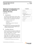
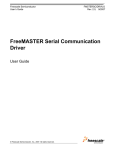
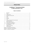
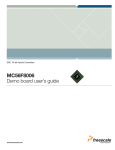
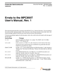
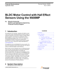
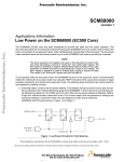
Freescale Semiconductor
User Guide
Document Number:LPWTUG
Rev. 0, October 2012
Low Power Wireless Transmitter
User’s Guide
Contents
1 Introduction
This reference design demonstrates a Freescale Qi-compliant
low-power wireless transmitter solution. It is focused on a
cost-effective, flexible, and highly integrated platform that
will highlight these features:
• Wide DC input voltage range of 5 V to 16 V with single
power stage
• Free positioning with multiple primary coils
• Simple and robust communication demodulation circuit
• Low-power standby operation
• Precise and reliable power transfer with digital PID
closed-loop control
• Interoperable operation with any receiver device with
WPC Qi logo
• Friendly user interface
This application is an open-source-based solution, which gives
users design freedom, allows products differentiation, and
providing access to essential Freescale wireless charging
embedded software libraries.
© 2012 Freescale Semiconductor, Inc.
1
Introduction................................................................1
2
About this document..................................................3
3
Warnings...................................................................3
4
Setup guide...............................................................4
5
FreeMASTER software installation..........................5
6
FreeMASTER control...............................................5
Introduction
Adapter
Receiver
Device with
“Qi” logo
JTAG Converter
+ Isolator
Freescale Low Power
Wireless Transmitter
Figure 1. Wireless charging system configuration
Figure 1 shows the complete wireless charging system proposed by Freescale. It contains:
• PC (for monitoring, controlling, and programming)
• JTAG converter with isolator (connection tool between target and PC)
• Wall adapter or other DC source (for powering the wireless transmitter)
• Any Qi-compliant receiver device
This user guide focuses only on how to correctly operate a Freescale low-power wireless transmitter. The detailed component
layout of the Freescale low-power wireless transmitter platform is shown in Figure 2, which contains:
• Freescale MC56F8006 DSC: CPU of platform
• Power sources: provides power for all components on platform
• Power stage: converts DC power to AC power
• Primary coil array: transmits power through generated magnetic field
• Sensing circuit: senses input voltage/current and coil voltage/current for power transfer control, power calculation, and
fault protection
• Resonant bank selection circuit: configures suitable primary coils and resonant capacitor for power transfer to support
free positioning function under full input voltage range and load range
• Communication demodulation circuit: demodulates communication signals to link with a receiver
• Human-machine interface: for monitoring, controlling, and debugging
HMI
Power source
MC56F8006
Communication
demodulation circuit
Sensing circuit
Power stage
Resonant bank
selection circuit
Primary coils
Figure 2. Layout of Freescale low-power wireless transmitter
Some key human interfaces are highlighted in Figure 3. They will be described in more detail later in this document when we
discuss setting up an operational system.
Low Power Wireless Transmitter User’s Guide, Rev. 0, October 2012
2
Freescale Semiconductor, Inc.
About this document
•
•
•
•
•
JTAG header: connects to JTAG converter for FreeMASTER connection and firmware programming
Power jack: connects to adapter or DC source
Coil mask: area to place receiver device
Enable button: to exit system from standby mode
Run status indicator: indicates system run status
• Off: standby mode
• Flashing: PING mode
• On: power transfer mode
• Fault indicator: indicates system fault status
• Off: no fault
• On: faults in system
Figure 3. Interfaces of Freescale low-power wireless transmitter
2 About this document
The key items can be found in the following sections of this document:
• Introduction to the demo: Section 1, “Introduction”
• Information about safety in using the demo: Section 3, “Warnings”
• System setup instructions: Section 4, “Setup guide”
• FreeMASTER installation: Section 5, “FreeMASTER software installation”
• Control via FreeMASTER: Section 6, “FreeMASTER control”
3 Warnings
The power stage includes power components that can reach temperatures hot enough to cause burns. To facilitate safe
operation, the DC input power should come from a DC power supply that is current limited to no more than 3 amps.
Keep the following points in mind while following the instructions in this guide:
• Power down the input supply source before moving scope probes, making connections, and so on.
• Follow proper safety procedures.
• Wear safety glasses.
• Remove all rings, watches, and jewelry or other metal belongings
• Use shields.
• Operation should be done only by personnel trained in power electronics lab techniques.
Low Power Wireless Transmitter User’s Guide, Rev. 0, October 2012
Freescale Semiconductor, Inc.
3
Setup guide
• Do not plug any other cables into the demo system except for the power supply cable.
• JTAG is only used for FreeMASTER connection (optional to run system) and firmware programming.
4 Setup guide
In order to correctly operate the Freescale low-power wireless transmitter demo, please perform the following instructions
step by step.
If FreeMASTER is not required to connect with the demo to monitor the system run status, please skip steps 1–4 and 6.
1. Properly connect the 14-pin JTAG connector of the Freescale JTAG converter to the JTAG header on the demo board.
Note that the red string of ribbon wire on the JTAG converter must be aligned with pin 1 of the JTAG header on the
demo board.
2. Properly connect the JTAG converter to the PC (USBTAP to USB port, parallel converter to parallel port).
3. Open FreeMASTER project in …\Project\FreeMASTER\Power Transmitter.pmp through the FreeMASTER
application. If FreeMASTER is not installed in your PC, please refer to section 5 for installation.
4. Correctly configure FreeMASTER options.
a. Click “Options…” command in “Project” menu of FreeMASTER application.
b. Select “Comm” tab in “Options” window.
c. A Plug-in Module has to be selected for FreeMASTER communication with the JTAG converter. Click the down
arrow button of the pulldown menu on the right side of the text box of the “Plug-in Module” item to select a
suitable plug-in connection: either FreeMASTER 56F8xxx Direct-LPT JTAG Communication Plugin item for
parallel converter, or FreeMASTER CodeWarrior-CCS JTAG/OnCE Communication Plugin for USBTAP.
d. Click the “Configure…” button to open the window of “Command Converter Server Settings”, keeping default
settings.
e. Click the "OK" button to complete configuring the command converter server settings (shown in Figure 4).
Figure 4. FreeMASTER settings – "Options: Comm"
f.
g.
h.
i.
Select the “MAP Files” tab in the “Options” window.
Open demo symbol file by clicking “…” open button.
Select symbol file of ptx.elf from the …\Project\Goal File folder.
Select file format “Binary ELF with DWARF1 or DWARF2 dbg format.” from pull-down menu by clicking the
down arrow button on the right side of the “File format” text box.
j. Click “OK” button to complete FreeMASTER options configuration (shown in Figure 5).
Low Power Wireless Transmitter User’s Guide, Rev. 0, October 2012
4
Freescale Semiconductor, Inc.
FreeMASTER software installation
Figure 5. FreeMASTER settings – "Options: MAP Files"
5. Power up the demo by plugging the output of a DC source (wall adapter) into the power jack on the demo board. The
system will stay in standby mode. The workable DC input voltage range is 5–16 V for this demo. If the voltage is less
than 6 V, use 3 A current rating; if it's above 6 V, use 2 A.
6. After the FreeMASTER options are configured, FreeMASTER communication can be started. To start/stop the
communication, click the red “STOP” button in the button toolbar of the FreeMASTER window (shown in Figure 6).
The system run status can be monitored and controlled via the FreeMASTER application. Please refer to FreeMASTER
control for more information.
Figure 6. FreeMASTER button toolbar
7. Place any Qi-compliant receiver device on top of the coil mask of the transmitter demo. Align the receiver coil on the
area of the transmitter primary coils to assure reliable power transfer.
8. Click the “Enable" button on the demo board to exit Standby mode and start receiver detection. The LED of the run
status indicator will start flashing. If there is no receiver or the receiver doesn't respond, the detection action will last
one minute, then the system will return to Standby mode (the LED of the run status indicator will be off).
9. When power transfer is successfully established, the LED of the run status indicator is on. The input current of the
transmitter demo or receiver output status can also indicate if the system successfully enters power transfer mode.
10. When power transfer is complete, the system will return to Standby mode, and the LED of the run status indicator will
be off. If the receiver is taken away when power is transferring, the system will restart to detect the receiver for one
minute. If there is no receiver or the receiver doesn't respond, the detection action will last one minute, then the system
will return to Standby mode.
11. If any system fault occurs, the fault indicator LED will turn on, and the system will stay in Fault mode. A fault status
can be cleared only by powering down the demo board.
5 FreeMASTER software installation
If there is no FreeMASTER application installed on the PC that you intend to use for to control the demo, you can find the
latest version of the installation file FMASTERSW.exe on the Freescale FreeMASTER web page, www.freescale.com/
freemaster. In case of any problem with the installation process or when using the software, download the user manual from
the Freescale web page.
6 FreeMASTER control
After launching the FreeMASTER application and performing all setup actions described above, FreeMASTER can
successfully set up communication with the demo board.
Low Power Wireless Transmitter User’s Guide, Rev. 0, October 2012
Freescale Semiconductor, Inc.
5
FreeMASTER control
In a FreeMASTER project, there is a Watch-Grid pane at the bottom of the application window. The Watch-Grid pane
contains the list of watch variables, which is used to observe/set the variable values (shown in Figure 7).
Figure 7. Watch-Grid pane
In addition, there are two types of charts (Scope and Recorder) to read application variables and plot them in a view panel.
While the Scope periodically reads variables and plots them in real time, the Recorder is running on the target board, reading
variables, and sending them to the FreeMASTER application in a burst mode fashion when the trigger event is detected by
the target. Therefore the Recorder enables use of a much shorter sampling period and can plot very quick actions. To open
either Recorder (telescope icon) or Scope (time line icon) view panel, select it from a list on the left project-tree window
(shown in Figure 8 —the Scope view panel of PID is open).
Figure 8. Scope view pane
Low Power Wireless Transmitter User’s Guide, Rev. 0, October 2012
6
Freescale Semiconductor, Inc.
FreeMASTER control
FreeMASTER is a free Freescale development tool, useful for accelerating development time in a project's R&D phase. A
"DIY" approach is encouraged to help you better debug your application per personalized requirements. The items are not
limited to those items shown in this document.
NOTE
Please refer to the FreeMASTER user manual for a complete list of features.
Low Power Wireless Transmitter User’s Guide, Rev. 0, October 2012
Freescale Semiconductor, Inc.
7
How to Reach Us:
Home Page:
www.freescale.com
Web Support:
http://www.freescale.com/support
USA/Europe or Locations Not Listed:
Freescale Semiconductor
Technical Information Center, EL516
2100 East Elliot Road
Tempe, Arizona 85284
+1-800-521-6274 or +1-480-768-2130
www.freescale.com/support
Europe, Middle East, and Africa:
Freescale Halbleiter Deutschland GmbH
Technical Information Center
Schatzbogen 7
81829 Muenchen, Germany
+44 1296 380 456 (English)
+46 8 52200080 (English)
+49 89 92103 559 (German)
+33 1 69 35 48 48 (French)
www.freescale.com/support
Japan:
Freescale Semiconductor Japan Ltd.
Headquarters
ARCO Tower 15F
1-8-1, Shimo-Meguro, Meguro-ku,
Tokyo 153-0064
Japan
0120 191014 or +81 3 5437 9125
[email protected]
Asia/Pacific:
Freescale Semiconductor China Ltd.
Exchange Building 23F
No. 118 Jianguo Road
Chaoyang District
Beijing 100022
China
+86 10 5879 8000
[email protected]
Document Number: LPWTUG
Rev. 0, October 2012
Information in this document is provided solely to enable system and software
implementers to use Freescale Semiconductors products. There are no express or implied
copyright licenses granted hereunder to design or fabricate any integrated circuits or
integrated circuits based on the information in this document.
Freescale Semiconductor reserves the right to make changes without further notice to any
products herein. Freescale Semiconductor makes no warranty, representation, or
guarantee regarding the suitability of its products for any particular purpose, nor does
Freescale Semiconductor assume any liability arising out of the application or use of any
product or circuit, and specifically disclaims any liability, including without limitation
consequential or incidental damages. "Typical" parameters that may be provided in
Freescale Semiconductor data sheets and/or specifications can and do vary in different
applications and actual performance may vary over time. All operating parameters,
including "Typicals", must be validated for each customer application by customer's
technical experts. Freescale Semiconductor does not convey any license under its patent
rights nor the rights of others. Freescale Semiconductor products are not designed,
intended, or authorized for use as components in systems intended for surgical implant
into the body, or other applications intended to support or sustain life, or for any other
application in which failure of the Freescale Semiconductor product could create a
situation where personal injury or death may occur. Should Buyer purchase or use
Freescale Semiconductor products for any such unintended or unauthorized application,
Buyer shall indemnify Freescale Semiconductor and its officers, employees, subsidiaries,
affiliates, and distributors harmless against all claims, costs, damages, and expenses, and
reasonable attorney fees arising out of, directly or indirectly, any claim of personal injury
or death associated with such unintended or unauthorized use, even if such claims alleges
that Freescale Semiconductor was negligent regarding the design or manufacture of
the part.
RoHS-compliant and/or Pb-free versions of Freescale products have the functionality and
electrical characteristics as their non-RoHS-complaint and/or non-Pb-free counterparts.
For further information, see http://www.freescale.com or contact your Freescale
sales representative.
For information on Freescale's Environmental Products program, go to
http://www.freescale.com/epp.
Freescale™ and the Freescale logo are trademarks of Freescale Semiconductor, Inc.
All other product or service names are the property of their respective owners.
© 2012 Freescale Semiconductor, Inc.