1
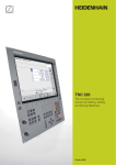
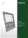
iTNC 530
The Versatile Contouring
Control for Milling, Drilling,
Boring Machines and
Machining Centers
March 2008
Start smart
For almost 30 years, TNC controls have
been proving themselves in daily use on
milling, drilling and boring machines, as
well as machining centers. This success
is due in part to their shop-oriented
programmability, but also to their
compatibility with programs of the
predecessor models.
With the new smarT.NC operating mode,
HEIDENHAIN has made yet another step
forward towards greater ease of use.
smarT.NC continues the success story of
this shop-floor programmable user
interface. Well-structured input forms,
straightforward graphic support, and
comprehensive help texts combine with
the easy-to-use pattern generator to form
a compelling programming environment.
And in spite of smarT.NC’s entirely different
user interface, it stands squarely on the
proven HEIDENHAIN plain language dialog.
Because in the background—out of view
for the user—smarT.NC generates the
program in conversational format.
HEIDENHAIN controls are powerful, userfriendly, and upwardly compatible so they
are prepared for the future and allow you
to look forward with confidence.
2
Contents
The iTNC 530...
Where can it be used?
Universally Applicable
4
– The right control for scores of applications
How does it look?
Well Designed and User Friendly
6
– The iTNC 530 in dialog with the user
How compatible is it?
Consistently Upward Compatible
8
– A promising future with HEIDENHAIN contouring controls
What can it do?
Machining with Five Axes
10
– The iTNC 530 permits optimum tool movement
– Swivel head and rotary table controlled by iTNC 530
Intelligent Machining
14
– Dynamic collision monitoring (DCM)
– Adaptive feed rate control (AFC)
– Global program settings
Higher Speed, More Accuracy, Truer Contours
18
– High speed milling with the iTNC 530
Automated Machining
20
– The iTNC 530 manages, measures and communicates
Minimize Setup Times
22
– The iTNC 530 makes setup easy
How is it programmed?
Programming, Editing, Testing
24
– The iTNC 530 opens endless possibilities
– Fast availability of all information
– Graphic support in any situation
Programming in the Workshop
28
– Straightforward function keys for complex contours
– Programming contours unconventionally
– Field-proven cycles for recurring operations
Well Thought Out, Simple and Flexible
32
– smarT.NC – the alternative operating mode
Open for Communication
34
– The iTNC 530 understands DXF files
– Program offline and enjoy the advantages of iTNC
– Fast data transfer with the iTNC 530
– The iTNC 530 with Windows XP
– The iTNC programming station
Are there any accessories?
Workpiece Measurement
40
– Setup, Presetting and Measuring with Touch Trigger Probes
Tool Measurement
41
– Measuring length, radius and wear right on the machine
Inspecting and Optimizing Machine Accuracy
42
– Calibrating Rotary Axes with KinematicsOpt (Option)
Positioning with the Electronic Handwheel
43
– Delicate axis traverse
... And If There’s a Problem?
44
– Diagnostics for HEIDENHAIN controls
... At a glance
Overview
– User Functions, Accessories, Options and Specifications
45
Universally Applicable
– The Right Control for Scores of Applications
The iTNC 530 is versatile. It adapts
optimally to the needs of your company—
regardless of whether you are
manufacturing single parts or batches,
simple or complex parts, whether your
shop works “on call” or is centrally
organized.
The iTNC 530 is flexible. Do you prefer to
work at the machine or at a programming
station? With the iTNC 530 you can easily
do both, because it is just as powerful in its
shop-floor programmability as it is for
offline programming:
You can program your own conventional
milling, drilling, and boring operations at
the machine in dialog with the control.
The iTNC 530 gives you optimal support
with smarT.NC or plain language—the
conversational guidance from
HEIDENHAIN—as well as with numerous
graphic aids including practice-oriented
fixed cycles. For simple work—such as
face milling—you need not write a
program, since it is easy to operate the
machine manually with the iTNC 530.
The iTNC 530 can be programmed
remotely just as well—for example on a
CAD/CAM system or at a HEIDENHAIN
programming station. Your Ethernet
interface guarantees very short transfer
times, even of long programs.
Universal milling machine
• Workshop programming in HEIDENHAIN
conversational format or with smarT.NC
• Upwardly compatible programs
• Fast presetting with HEIDENHAIN 3-D
touch probe
• Electronic handwheel
High speed milling
• Fast block processing
• Short control-loop cycle time
• Jerk-free path control
• High spindle speed
• Fast data transfer
Five-axis machining with swivel head
and rotary table
• When you are programming away from
the machine, the iTNC 530 automatically
takes the machine geometry into
account
• Tilting the working plane
• Cylindrical surface machining
• Tool Center Point Management (TCPM)
• 3-D tool compensation
• Fast execution through short block
processing times
4
The iTNC 530 is universal. Its broad and
complex range of applications proves it.
Whether on simple 3-axis universal milling
machines in tool and mold making, or on
machining centers in interlinked
production—in either case, the iTNC 530
is the right control. And it offers the
applicable features both necessary and
helpful.
Five-axis machining on very large
machines
• Inspecting and optimizing machine
accuracy with KinematicsOpt
• Global program settings for
superimposition of various functions
• Procedure with handwheel
superimposition in the virtual tool axis
Drilling and boring
• Cycles for drilling, boring and spindle
alignment
• Drilling oblique holes
• Control of quills (parallel axes)
Machining centers and automated
machining
• Tool management
• Pallet management
• Tool-oriented machining
• Controlled presetting
• Reference-point management with
preset tables
• Automatic workpiece measurement with
HEIDENHAIN 3-D touch probes
• Automatic tool measurement and
breakage inspection
• Connection with host computer
5
Well Designed and User Friendly
– The iTNC 530 in Dialog with the User
The monitor
The TFT 15-inch color monitor shows a
clear overview of all relevant information
for programming, operating and monitoring
the machine tool and control such as
program blocks, comments and error
messages. More information is provided
through graphic support during program
entry, test run and actual machining.
The selectable “split screen” display
shows the part program blocks in one half
of the screen and the graphics or the
status display in the other half.
During the course of the program, status
displays will always offer information on
tool position, the current program, active
cycles and coordinate transformations, and
other data. The iTNC 530 even shows the
current machining time.
The keyboard
As with all TNCs from HEIDENHAIN, the
keyboard is tailored to the programming
process. The well thought-out configuration
of keys facilitates program input. Simple
words and abbreviations or unambiguous
symbols clearly indicate each key’s function.
Certain functions are entered through the
iTNC 530’s soft keys. The control is also
equipped with a QWERTY alphabetic
keyboard for DIN/ISO programming or for
adding comments to a program. And it
features a complete set of PC keys and a
touchpad for using Windows functions.
6
Keys on the monitor
The smarT.NC mode is activated
with a separate key and can be
navigated with additional green
keys.
Select the screen layout
Display machine mode or
programming mode
Soft keys for selecting
functions in screen
Shift between soft-key rows
Keys on the control panel
Program/file management, TNC functions
Programming modes
Program management:
Manipulate and delete programs
Programming and editing
Supplementary operating modes
Test run with graphic simulation
HELP function
Straight line, chamfer
Display error messages
Circular arc with center point
Show pocket calculator
Circular path with known radius
Machine operating modes
Circular arc starting tangentially
Manual Operation
Corner rounding
Electronic Handwheel
Contour approach and departure
Positioning with Manual Data Input
Free contour programming
Program Run, Single Block
Entry of polar coordinates
Program Run, Full Sequence
Entry of incremental dimensions
smarT.NC
Entry of a parameter instead of a
fixed numerical value/Definition of
parameters
Navigation
With the gray path function keys
and conversational guidance, you
program line segments and
circular arcs defined in various
ways.
Many functions are entered by
soft key.
Transfer of actual position to
program
Definition and calling of tools
smarT.NC: Select next form
smarT.NC: Select previous/next
frame
Definition and calling of cycles
Labeling and calling of subroutines
and program repeats
Use the blue keys on the
alphabetic keyboard to enter
programs in accordance with
the DIN/ISO standard.
Programmable program call
Programmed stop, interrupt/
discontinue
Touch probe functions
Special functions, e.g. TCPM or
PLANE
7
Consistently Upward Compatible
– A Promising Future with HEIDENHAIN Contouring Controls
For over 20 years, HEIDENHAIN has been
providing customers with contouring
controls for milling, drilling and boring. Of
course the controls have undergone
development during this period: many new
features have been added—also for more
complex machines with more axes. The
basic operational technique, however, has
remained the same. The machinist who
has been working with TNC does not have
to relearn. On the iTNC 530 he immediately
uses all of his previous experience with
TNCs, programming and working as
before.
2004: iTNC 530
with smarT.NC
2003: iTNC 530 with
Windows XP
2001: iTNC 530
1997: TNC 426 M
TNC 430
1993: TNC 426 C/P
These contouring keys from the TNC 145
are also on the iTNC 530
1988: TNC 407
TNC 415
1987: TNC 355
1984: TNC 155
1983: TNC 150
8
1981: TNC 145,
the first contouring
control from
HEIDENHAIN
“Old” programs also run on newer
TNC controls
Part programs from your NC program
archive that were written on older TNC
contouring controls can also be run on an
iTNC 530 with very little effort. This
ensures the greatest possible flexibility in
machine utilization and provides enormous
cost benefits if you find you have to
produce “old” parts again. HEIDENHAIN
contouring controls put you in the position
to manufacture a replacement part quickly
and economically even now—after more
than 20 years—without having to
reprogram it.
Familiar function keys take on new
tasks
Of course many innovations and
improvements have been included in
the iTNC 530—but the fundamental
programming procedure has remained
the same. When you switch to a new
control you do not need to relearn the
programming and operation. You only
need to become familiar with the new
functions. So you can apply your
professional knowledge as a machinist
immediately even on a new TNC control.
Inside contour—
programmed with the TNC 145...
...machined with the iTNC 530
9
Machining with Five Axes
– The iTNC 530 Permits Optimum Tool Movement
Modern machines often work with four or
five positioning axes. This makes it possible
to machine complex 3-D contours. The
required programs are usually created on
external CAD/CAM systems and comprise
a large number of very short line segments
that are transferred to the control. Whether
the workpiece is actually machined according
the program’s instructions depends
essentially on the geometric behavior of
the control. With its optimized path control,
its precalculation of the contour and its
algorithms for jerk limitation, the iTNC 530
has the right functions for a perfect surface
in the shortest possible machining time.
See for yourself. In the end, it’s the quality
of the workpiece that proves the
performance of the control.
10
3-D contour machining at its finest
The iTNC 530’s short block processing
time of only 0.5 ms for a 3-D line segment
without tool compensation permits high
traversing speeds even on complex
contours. This enables you, for example,
to mill molds or dies approximated with
0.2 mm line segments at feed rates as
high as 24 meters per minute.
The particularly jerk-free path control
when machining 3-D figures and the
defined rounding of series of straight-line
segments provide you with smoother
surfaces as well as high dimensional
accuracy.
The iTNC 530 thinks ahead. Its “lookahead” function anticipates future changes
in direction by adjusting the traversing
speed to the programmed surface. If
desired, it also enables the iTNC 530 to
reduce the feed rate when plunging the
tool into the workpiece. This lets you
simply program the maximum machining
speed as the feed rate. The iTNC 530
automatically adapts the actual speed of
the workpiece contour to save you
machining time.
For NC programs with normal vectors,
such as those generated by CAD/CAM
systems, the iTNC 530 automatically
calculates a 3-D tool compensation for end
mills, ball-nose cutters, or toroid cutters.
Guided tool tip
CAD/CAM systems use postprocessors to
generate five-axis programs. In principle,
such programs contain either all coordinates
of the machine’s existing NC axes, or NC
blocks with surface normal vectors. When
machining with five axes (three linear axes
and two tilting axes)*, the tool can stay
perpendicular, or if desired, inclined at a
predetermined angle to the workpiece
surface.
Regardless of what type of 5-axis programs
you wish to run, the iTNC 530 makes all
the compensating movements in the linear
axes that result from movements in the
tilting axes. The iTNC 530’s Tool Center
Point Management feature (TCPM)—an
improvement upon the proven TNC function
M128—provides optimal tool guidance and
prevents contour gouging.
With TCPM you can define the behavior of
the tilting and compensating movements
automatically calculated by the iTNC 530.
TCPM defines the interpolation between
the start and end positions:
• During face milling—machining mainly
with the front face of the tool—the tool
point moves on a straight line. The path
of the tool’s cylindrical surface is not
defined, but rather it depends on the
machine geometry.
• During peripheral milling machining is
mainly by the side of the tool. The tool tip
also travels on a straight path, but
additionally the tool’s circumference
machines an explicitly defined plane.
TCPM defines the effect of the
programmed feed rate as desired either...
• as the actual velocity of the tool tip relative
to the workpiece. Very high axis feed
rates can result from large compensating
motions during machining near the
center of tilting.
• as contouring feed rate of the axes
programmed in the NC block. The feed
rate is usually lower, but you attain better
surface quality during large compensating
movements.
With TCPM you can also define the effect
of the inclination angle for more uniform
cutting passes when working with an
inclined radius cutter:
• Angle of inclination defined as axis angle
• Angle of inclination defined as spatial
angle
The iTNC takes the inclination angle into
account in all 3-D machining—even with
45° swivel heads or tilting tables. You either
specify the angle of inclination in the NC
program via a miscellaneous function, or
adjust it manually with an electronic
handwheel. The iTNC 530 makes sure that
the tool remains on the contour and does
not damage the workpiece.
* These functions must be implemented by the
machine tool builder.
11
Machining with Five Axes
– Swivel Head and Rotary Table Controlled by iTNC
Many five-axis operations that at first
glance may seem very complex can be
reduced to conventional 2-D movements
that are simply tilted about one or more
rotary axes or wrapped onto a cylindrical
surface. The iTNC supports you with
application-oriented functions to help you
write and edit such programs quickly and
simply without a CAD/CAM system.
Tilting the working plane*
Programs for contours and holes on
inclined surfaces are often very complex
and require time-consuming computing
and programming work. Here the
iTNC 530 helps you to save a great deal
of programming time.
You program the part as usual in the
working plane (e.g. the X/Y plane), but it is
machined in a plane that is rotated in one
or more axes about the main plane.
The PLANE feature makes it easy to define
a tilted working plane: You can specify tilted
working planes in seven different ways,
depending on the information on the
workpiece drawing. In order to keep the
12
use of these complex functions as simple
as possible, a separate animation is
available for each possible plane definition,
so that you can view them before selecting
the function. Clearly arranged support
graphics assist you during input.
You can define the rotary positioning
behavior with the PLANE function so that
there are no unpleasant surprises when
the program is run. The settings for
defining the positioning behavior are
identical for all PLANE functions, making
everything that much easier.
* These functions must be implemented by the
machine tool builder.
Machining cylindrical surfaces*
With the iTNC 530 it is quite easy to program
contours (which consist of straight lines
and arcs) on cylindrical surfaces using rotary
and tilting tables: You simply program the
contour in a plane as if the cylinder surface
were unrolled. The iTNC 530 then executes
the operation on the surface of the cylinder.
The iTNC 530 features four cycles for
cylindrical surface machining:
• Slot milling (the slot width is the same as
the tool diameter)
• Guide-groove milling (the slot width is
greater than the tool diameter)
• Ridge milling
• Mill outside of contour
Manual axis motion in the tool direction
on 5-axis machines
The safe retraction of a tool is very important
with five-axis machining. The “virtual tool
axis” function is of assistance here. You
can use it to traverse the tool in the current
direction of the tool axis via the external
direction keys or the handwheel. This
function is especially useful if you want to
• retract the tool in the direction of the tool
axis during interruption of a five-axis
machining program, or
• use the handwheel or external direction
keys to perform an operation in Manual
mode and the tool is in contact.
• move the tool with the handwheel in the
active tool axis direction during
machining.
Linear feed rate for rotary tables in
mm/min*
While the standard units of measure for
programming feed rates for rotary tables
are degrees per minute, the iTNC 530 can
also interpret a feed rate programmed in
millimeters or inches per minute. The feed
rate at the contour is then independent of
the distance of the tool center from the
center of the rotary axis.
* These functions must be implemented by the
machine tool builder.
13
Intelligent Machining
– Dynamic Collision Monitoring Option (DCM)
The complex motions and high traversing
speeds of five-axis machining make axis
movements difficult to foresee. This makes
collision monitoring a valuable function that
relieves the machine operator and protects
the machine from damage.
NC programs from CAM systems may
avoid collisions of the tool or tool holder
with the workpiece, but unless you invest
in expensive offline machine simulation
software they ignore the machine
components located within the work
envelope. And even then it cannot be
guaranteed that machine conditions, such
as the fixture position, will be identical to
those of the simulation. In the worst case,
a collision will remain undetected until the
damage is done.
In cases such as these, the machine
operator is supported by the DCM dynamic
collision monitoring* feature of the
iTNC 530 (only runs on the MC422 B/C).
The control interrupts machining whenever
a collision is imminent, thereby increasing
the safety for the machine and its operator.
This helps to prevent machine damage,
which can result in costly downtimes.
Unattended shifts become safer and more
reliable.
However, DCM works not only in automatic
mode. It is also active in manual operation.
If, for example, during setup the machine
operator takes a collision course to a
component in the working space, the
iTNC 530 detects it, stops axis movement,
and issues an error message.
If two machine components come too
close to each other, there are three
warning stages:
• Advance warning if below 14 mm
clearance
• Warning if below 8 mm clearance
• Error if below 2 mm clearance
* These functions must be implemented by the
machine tool builder.
14
Of course the iTNC 530 also shows the
machine operator—both with an error
message and graphically—which machine
components are endangered. If a collision
warning is displayed, the TNC permits
retracting the tool only in those directions
which increase the clearance between the
colliding objects.
The machine tool builder takes care of the
required definition of machine components.
The working space and the collision objects
are described using geometric bodies such
as planes, cubes and cylinders. Complex
machine components can be modeled with
multiple geometric bodies. The tool is
automatically considered a cylinder of the
tool radius (defined in the tool table). For
tilting devices, the machine tool builder can
use the tables for the machine kinematics
also to define the collision objects.
The last step of the configuration process
is defining which machine components can
collide. Because the machine design in
itself prevents collisions between certain
machine components, they can be ruled
out from the start. For example, a tool
touch probe like the HEIDENHAIN TT
clamped on the machine table can never
come into contact with the machine cabin.
When using the dynamic collision
monitoring, please note:
• While DCM can help reduce the danger
of collision, it cannot eliminate it.
• Only the machine manufacturer can
define collision objects.
• Collisions between machine
components (such as swivel heads) and
the workpiece cannot be detected.
• Handwheel superimposition (M118) is
not possible.
• DCM cannot be used during operation in
following error mode (which means
without feedforward).
• It is not possible to monitor for collision
before machining.
15
Intelligent Machining
– Option for Adaptive Feed Rate Control (AFC)
Besides the feed rate for each block or
cycle, HEIDENHAIN controls have always
allowed the programmer to enter a manual
compensation through the override
potentiometer to adjust for the actual
machining situation. But this always
depends on the experience and, of course,
the presence of the operator.
Adaptive feed rate control (AFC) automatically
regulates the feed rate of the TNC, taking
into consideration the respective spindle
power and other process data.
In a teach-in cut, the iTNC records the
maximum spindle power. Then, before
actual machining, you define in a table the
respective limit values between which the
iTNC can influence the feed rate in the
adaptive control mode in the “control” mode.
Of course, various overload reactions can
be provided for, which can also be defined
by your machine tool builder.
16
Adaptive feed rate control offers various
advantages:
Optimizing the machining time
Fluctuations in dimensions or material
(blowholes) often appear particularly on
cast parts. With a corresponding adaptation
of the feed rate, the control tries to keep
the previously "learned" maximum spindle
power during the entire machining time.
The total machining time is shortened by
an increased feed rate in the machining
zones with less stock removal.
Tool monitoring
The iTNC’s adaptive feed rate control
permanently compares the spindle power
with the feed rate. As a tool becomes
blunt, the spindle power increases. As a
result, the iTNC reduces the feed rate. As
soon as the feed rate falls below a defined
minimum, the iTNC reacts with an error
message or by switching off. This prevents
damage resulting from tool breakage or
wear.
Protection of the machine mechanics
Reducing the feed rate down to the
reference value whenever the learned
maximum permissible spindle power is
exceeded also reduces the strain and wear
on the machine. It effectively protects the
spindle from overload.
– Global Program Settings (Option)
The global program settings, which come
into play particularly in large-scale mold
making, are available in the Program Run
and MDI modes. It allows you to define
various coordinate transformations and
settings with global and priority effect for
the selected NC program, without having
to edit it.
You can change the global program settings
during a program stop even in mid-program.
After program start the iTNC then moves,
if necessary, to a new position with a
positioning logic influenced by you.
The following functions are available:
• Exchanging axes
• Additional, additive datum shift
• Superimposed mirroring
• Axis locking
• Handwheel superimposition, with axisspecific memory of paths covered per
handwheel, also in virtual axis direction
• Superimposed basic rotation
• Superimposed rotation
• Globally valid feed-rate factor
17
Higher Speed, More Accuracy, Truer Contours
– High Speed Milling with the iTNC 530
High speed cutting
High speed cutting stands for quick and
efficient contour milling. The control must
be able to transfer large amounts of data
quickly, make long programs efficient to
edit, and produce the desired ideal contour
on the workpiece—all qualities that the
iTNC 530 possesses.
18
Very short block processing times
Sophisticated feedforward servo methods
are progressively pushing block processing
as an influence ever further into the
background. Nevertheless, short block
processing times remain the best solution
for certain machining tasks. One example
is the machining of highly accurate
contours with very high resolution. This is
no problem for the iTNC 530. Here the
control provides ideal performance with
block processing times of less than one
millisecond.
Very high contour accuracy
The iTNC 530 calculates the contour for up
to 1024 blocks in advance. This enables it
to adapt the axis velocities to the contour
transitions. It controls the axes with special
algorithms that ensure path control with
the required limits to velocity and
acceleration. The integrated filters can
specifically suppress the natural frequencies
of an individual machine while maintaining
the desired surface accuracy.
Fast machining at specified accuracy
You as user specify the accuracy of the
machine contour—apart from the NC
program. You simply enter in the control
through a cycle the maximum permissible
deviations from the ideal contour. The
iTNC 530 automatically adapts the
machining to the tolerance that you define.
No contour damage occurs with this
method.
Spline interpolation
If your CAD/CAM system describes
contours as splines, you can transfer them
directly to the control. The iTNC 530
features a spline interpolator and can
process third-degree polynomials.
Digital drive technology
The position controller, speed controller
and, if required, the current controller are
integrated in the iTNC 530. The digital
motor control makes it possible to attain
very high feed rates. While interpolating
simultaneously in up to five axes, the
iTNC 530 reaches the required cutting
speeds by digitally controlling spindle
speeds up to 60 000 rpm.
19
Automated Machining
– The iTNC 530 Manages, Measures and Communicates
The difference in requirements placed
on the classical machine for tool and
mold-making and machining centers are
becoming ever less distinct. Today of
course the iTNC 530 is particularly capable
of controlling automated processes. It
masters the range of functions needed to
start the proper machining operations on
individual workpieces in any setup and
even in interlinked machining.
20
Tool management
For machining centers with automatic tool
changers, the iTNC 530 offers a central tool
file for up to 32 767 tools. The tool memory
is a freely configurable file and can therefore
be optimally fitted to your needs. You can
even have the iTNC 530 manage your tool
names. The control prepares the next tool
change while the current tool is still cutting.
This significantly reduces the non-cutting
time required for changing tools.
Pallet management
The iTNC 530 can assign the appropriate
program and datum shift to parts mounted
on pallets and brought to the machine in a
random sequence. If a pallet is exchanged,
the iTNC 530 automatically calls the correct
part program. This permits automatic
machining of a variety of parts in any
sequence.
Tool-oriented machining
With tool-oriented machining, one machining
step is performed on all workpieces on a
pallet before the next machining step. This
reduces the number of tool changes to a
necessary minimum and the machining
time is significantly shorter.
The iTNC 530 supports you with
convenient input forms with which you can
assign a tool-oriented machining operation
to a pallet with several workpieces on
several fixtures. You can write the program,
however, in the familiar workpiece-oriented
sequence.
You can also use this function even if your
machine does not support pallet
management. In the pallet file you then
simply define the positions of the
workpieces on your machining table.
Inspecting workpieces for proper
machining and dimensional accuracy
The iTNC 530 features a number of
measuring cycles for checking the
geometry of the machined workpieces.
To run the measuring cycles, you insert a
3-D touch probe from HEIDENHAIN (see
page 40) into the spindle in place of a tool
for the following tasks:
• Recognizing a workpiece and calling the
appropriate part program
• Checking whether all machining
operations were conducted correctly
• Determining infeeds for finishing
• Detecting and compensating tool wear
• Checking workpiece geometry and
sorting parts
• Logging measured data
• Ascertaining machining error trends
Workpiece measurement and automatic
compensation of tool data
Together with the TT 140, TL Nano and
TL Micro systems for tool measurement
(see page 41), the iTNC 530 can
automatically measure tools while they are
in the machine. The iTNC 530 saves the
ascertained values of tool length and radius
in the central tool file. By inspecting the
tool during machining you can quickly and
directly measure wear or breakage to
prevent scrap or rework. If the measured
deviations lie outside the tolerances, or if
the monitored life of the tool is exceeded,
the iTNC 530 locks the tool and
automatically inserts a replacement tool.
21
Minimize Setup Times
– The iTNC 530 Makes Setup Easy
Before you can begin machining, you must
first clamp the tool and set up the machine,
find the position and orientation of the
workpiece on the machine, and set the
workpiece reference point. This is a timeconsuming but indispensable procedure.
After all, any error directly reduces the
machining accuracy. Particularly in small
and medium-sized production runs, as well
as for very large workpieces, setup times
become quite a significant factor.
The iTNC 530 features application-oriented,
real-world setup functions. They support
the user, help to reduce non-productive
time, and make overnight, unattended
production possible. Together with the
3-D touch probes, the iTNC 530 offers
numerous probing cycles for automatic
alignment of the workpieces, presetting,
and measurement of the workpiece and
the tool.
22
Delicate manual traverse
For setup, you can use the direction keys
to move the machine axes manually or in
incremental jog. A simpler and more
reliable way, however, is to use the
electronic handwheels from HEIDENHAIN
(see page 42). Particularly with the portable
handwheels you are always close to the
action, enjoy a close-up view of the setup
process, and can control the infeed
responsively and precisely.
Workpiece alignment
With the 3-D touch probes from
HEIDENHAIN (see page 40) and the probing
functions of the iTNC 530, you can forgo
any tedious manual alignment of the
workpiece:
• Clamp the workpiece in any position.
• The touch probe ascertains the
workpiece misalignment by probing a
surface, two holes, or two studs.
• The iTNC 530 compensates the
misalignment with a “basic rotation,”
which means that in the NC program the
part is rotated by the measured
misalignment.
Compensating workpiece misalignment
Compensate misalignment by rotating the
coordinate system or turning the table
Workpiece presetting
You can use a reference point to assign a
defined value in the iTNC display to any
workpiece position. Finding this point
quickly and reliably reduces nonproductive
time and increases machining accuracy.
The iTNC 530 features probing cycles for
automatic presetting. Once found, you can
save reference points
• in the workpiece preset table,
• in a workpiece datum table, or
• by directly setting the displayed value.
Preset table: The iTNC’s central reference
point management
The preset table makes flexible machining,
shorter setup times and increased
productivity possible. In other words, it
makes it much easier to set up the
machine.
In the preset table you can save any
number of reference points and assign an
individual basic rotation to each one.
When working in a tilted plane and
presetting a reference point, the iTNC
includes the respective positions of the
rotary axes. In this way, the reference point
also remains active in any other angular
position.
On machines with an automatic spindle
head changer, the reference point remains
unchanged after a head exchange, even if
the heads differ in their kinematics (i.e. in
their dimensions).
The iTNC automatically creates separate
preset tables for individual traverse ranges
(such as for alternating table machining)
When changing traverse ranges, the iTNC
activates the correct preset table with the
most recently active reference point.
There are three ways to save reference
points in the preset table:
• In the Manual mode by soft key
• By using the probing functions
• With the automatic probing cycles
Workpiece presetting
At a corner, for example, or in the center of
a bolt hole circle
23
Programming, Editing, Testing
– The iTNC 530 Opens Endless Possibilities
The iTNC 530 is just as universal in
application as it is flexible in machining and
programming.
Programming at the machine
HEIDENHAIN controls are workshop
oriented, which means that they were
conceived for programming right at the
machine. The iTNC 530 supports you with
two user interfaces:
For almost 30 years, HEIDENHAIN
conversational programming has been
the standard programming language for all
TNC controls and for shop-floor programming
in general. The new smarT.NC intuitive
and self-explanatory operating mode uses
straightforward input forms to guide you
through the complete NC programming
process all the way to the actual machining.
There’s no need to learn G functions or
any special programming languages. The
control “speaks” with you using easily
understandable questions and prompts.
Whether plain-language prompts, dialog
guidance, programming steps or soft keys,
all texts are available in numerous
languages.
If you are used to DIN/ISO programming,
however, the iTNC is still the right control—
you can enter DIN/ISO programs over the
alphanumeric keyboard. The most
frequently needed letters are already
highlighted in color.
Positioning with manual data input
You can start working with the iTNC 530
even before writing a complete part
program. Simply machine a part step by
step—switching as you want between
manual operation and automatic
positioning.
Creating programs offline
The iTNC 530 is also well equipped for
offline programming. The iTNC 530 can be
integrated through its interfaces into
networks and connected with programming
stations, CAD/CAM systems or other data
storage devices.
24
– Fast Availability of All Information
Do you have questions on a programming
step but your User’s Manual is not at hand?
No problem: The iTNC 530 numerical
control and iTNC 530 programming station
now feature TNCguide, a convenient help
system that can show the user
documentation in a separate window.
You can activate the TNCguide by simply
pressing the help key on the iTNC
keyboard or by clicking any soft key with a
cursor in the shape of a question mark.
You switch the cursor by simply clicking the
help symbol ( ) that appears on all TNC
screens.
TNCguide
integrated in the
control, e.g. on the
iTNC 530 ...
The TNCguide usually displays the
information in the immediate context of
the element in question (context-sensitive
help). This means that you immediately
receive the relevant information. This
function is particularly helpful with the soft
keys. The method and effect of operation is
explained in detail.
The iTNC 530 is shipped with integrated
documentation for the respective NC
software in English and German. Other
languages are available for download free
of charge as soon as the translations
become available. After download, you can
save the national language files in the
corresponding language directory on the
TNC’s hard disk.
… or at the
programming
station.
The following manuals are available in the
help system:
• User’s Manual for Conversational
Programming
• User’s Manual for smarT.NC (same
format as a “Pilot”)
• User’s Manual for Touch Probe Cycles
• User’s Manual for DIN/ISO Programming
• User’s Manual for the iTNC 530
Programming Station (only included in
the programming station)
* Only with at least 256 MB RAM
25
Programming, Editing, Testing
– Graphic Support in Any Situation
Programming graphics
The two-dimensional programming
graphics give you additional security: while
you are programming, the iTNC 530 draws
every entered traverse command on the
screen.
3-D line graphics
The 3-D line graphics display the
programmed tool center point path in three
dimensions. With the powerful zoom
function you can also see the finest details.
You should especially use the 3-D line
graphics to inspect programs created
offline for irregularities before machining, in
order to avoid undesirable traces of the
machining process on the workpiece, e. g.
when points are output incorrectly by the
postprocessor. In order to find the error
location quickly, the currently active block
of the 3-D line graphics appears highlighted
in the left window. In addition, the
respective programmed end points can be
displayed to show any concentrations of
points.
Help graphics
During cycle programming in the plainlanguage dialog, the iTNC shows a separate
illustration for each parameter. This makes
it easier to understand the function and
accelerates programming. In smarT.NC you
will find help graphics for all required input.
26
Program verification graphics
To play it safe before running a program,
the iTNC 530 can graphically simulate the
machining of the workpiece. It can display
the simulation in the following ways:
• In a plan view with different shades of
depth
• In three planes (as in the workpiece
drawing)
• In a solid model, 3-D view
Details can be displayed in magnification.
The high resolution of the 3-D view visualizes
even very fine contours true to detail and
enables you to see even hidden details
clearly and reliably. A simulated light source
provides realistic light-and-shadow
conditions.
When testing complex five-axis programs,
even operations with tilted planes or
multi-side machining can be displayed.
In addition, the iTNC 530 indicates the
calculated machining time in hours, minutes
and seconds.
Program-run graphics
On the iTNC 530, you can run the
programming graphics or verification
graphics even while the workpiece is being
machined. Also, it shows a real-time
graphic of the machining progress during
program run. Coolant spray and protective
enclosures usually obstruct any direct view
of the actual workpiece. You can get around
this with a simple keystroke to see the
simulated progress of workpiece
machining.
27
Programming in the Workshop
– Straightforward Function Keys for Complex Contours
Programming 2-D-Contours
2-D contours are the daily bread of the
modern machine shop. The iTNC 530 offers
a variety of possibilities here.
Programming with path function keys
If contours are dimensioned for NC, which
means that the end points are specified in
Cartesian or polar coordinates, then you
can program them directly with the path
function keys.
Straight and circular contour elements
To program a line segment, for example,
simply press the key for linear traverse. The
iTNC 530 asks for all information required
for a complete programming block, such as
target coordinates, feed rate, cutter radius
compensation and machine functions.
Appropriate path function keys for circular
movement, chamfers, and corner rounding
simplify your programming. To avoid
surface blemishes during approach or
departure from the contour, it must be
approached smoothly—that is, tangentially.
Circular path defined
by its end point, with
a smooth (tangential)
departure from the
previous contour
element
Circular path defined
by its center point,
end point, and
rotational direction
You simply specify the starting or end point
of the contour and the approaching or
departing radius of the cutter edge—the
control does the rest for you.
The iTNC 530 can look ahead over a radiuscompensated contour for up to 99 blocks
to watch for back cutting and avoid contour
damage such as can occur when roughing
a contour with a large tool.
Straight line defined
by its end point
Rounding: circular path defined
by radius and corner
point, with a smooth
(tangential) transition
to its adjoining contour
elements
Chamfer:
defined by the
corner point and the
chamfer length
Circular path defined
by its radius, end point
and rotational
direction
28
– Programming Contours Unconventionally
Ø 10
62
R12
18
¬ 12
45°
4
R3
R12
R1
0
R12
R34
0
R1
FK free contour programming
Not all workpieces are dimensioned for
conventional NC programming. Thanks to
FK, the iTNC’s free contour programming
feature, in such cases you simply type in
the known data—without first having to
convert or calculate your data! It does not
matter if individual contour elements are
not completely defined as long as the
complete contour has been. If the given
data result in more than one mathematical
solution, the helpful iTNC 530 programming
graphics present the possible variants for
your selection.
R10
Ø 10
50
29
Programming in the Workshop
– Field-Proven Cycles for Recurring Operations
Comprehensive Fixed Cycles for
Milling, Drilling and Boring
Frequently recurring operations that
comprise several working steps are stored
in the iTNC 530 as cycles. You program
them under conversational guidance and
supported by graphics that clearly illustrate
the required input parameters.
Cycles for complex contours
SL cycles (SL = Subcontour List) are
particularly helpful for clearing pockets with
combined contours. This term is used to
identify machining cycles for pilot drilling,
roughing and finishing when the contour or
subcontours are specified in subroutines.
In this way, one contour description can be
used for more than one operation using
different tools.
Up to twelve subcontours can be
superimposed for machining. The control
automatically calculates the resulting
contour and the tool paths for roughing or
clearing the surfaces. Subcontours can be
pockets or islands. Different components
are combined to form a single pocket in
which the tool circumnavigates the islands.
The iTNC 530 maintains a finishing
allowance on the wall and floor surfaces
during roughing. When roughing with
different tools, the control identifies
material remaining in inside corners so that
it can be cleared later with smaller tools.
A separate cycle is used for milling to the
finished dimension.
You can also program “open” contours
with the SL cycles. This enables the
iTNC 530 to observe allowances for 2-D
contours, to move the tool in alternating
directions after each infeed, to avoid
contour damage at undercuts and to
maintain the defined milling direction
(climb or conventional) after coordinate
transformations such as mirroring.
Standard cycles
Besides the fixed cycles for drilling, tapping
(with or without floating tap holder), thread
milling, reaming and boring, there are
cycles for hole patterns and milling cycles
for clearing plane surfaces, and for
roughing and finishing pockets, slots and
studs.
30
You can assign a separate depth to each
subcontour. If the subcontour is an island,
the iTNC interprets the “depth” entered as
the height of the island.
OEM cycles
As original equipment manufacturers
(OEMs), machine tool builders can
contribute their special manufacturing
know-how by designing additional fixed
cycles and saving them in the iTNC 530.
However, the end user can write his own
cycles as well. HEIDENHAIN makes this
possible with its PC program CycleDesign.
CycleDesign enables you to organize the
input parameters and soft-key structure of
the iTNC 530 to suit your own needs.
3-D machining with parametric
programming
With parameter functions you can program
simple 3-D geometric figures that can
easily be described mathematically. Here
you can use the basic arithmetical operations,
trigonometric functions, roots, powers,
logarithmic functions, parentheses, and
logical comparisons with conditional jump
instructions. Parametric programming also
offers you a simple method of realizing 3-D
operations for which there are no standard
cycles. Of course, parametric programming
is also suited for 2-D contours that cannot
be described with line segments or circular
arcs, but rather through mathematical
functions.
Coordinate transformation
If you should need a contour that has already
been programmed at another position or in
a different size, the iTNC 530 offers you a
simple solution:
Coordinate transformation
With coordinate transformation you can, for
example, rotate or mirror the coordinate
system or shift the datum. With a scaling
factor you can enlarge or reduce contours
to respect shrinkage allowance or
oversizes.
31
Well Thought Out, Simple and Flexible
– smarT.NC — The Alternative Operating Mode
TNC controls from HEIDENHAIN have
always been user friendly: Thanks to their
simple programming in HEIDENHAIN
conversational language, field-proven
cycles, unambiguous function keys, and
clear and vivid graphic functions, they have
grown over the last 30 years to become
one of the most popular shop-floor
programmable controls.
The alternative smarT.NC operating mode
makes programming even easier. With the
well thought-out input forms, you can
create your NC program in a few quick
steps. Of course you’ll be aided by help
graphics. As always, HEIDENHAIN has also
placed great value on compatibility. You can
switch at any time between smarT.NC and
conversational programming. But not only
can you write programs with smarT.NC—
you can test and run them as well.
32
Programming made simple
With smarT.NC, you program with the aid
of easy-to-use, unambiguous forms. For
simple operations, you need only enter a
few machining data. With smarT.NC, you
define such a machining step simply and
quickly in a single overview window.
Of course, if required, you can define
additional machining options. These options
are available in subforms in which, with a
few additional keystrokes, you can enter
the parameters for machining options.
You can define other functions, such as
measuring cycles, in separate forms.
Stay simple and flexible when
programming machining patterns
Machining positions are often arranged in
patterns on the workpiece. With the
pattern generator in smarT.NC, you can
program very diverse machining patterns
simply and extremely flexibly—of course
with graphic support.
You can define as many point patterns as
desired with various numbers of points in
one file. smarT.NC displays the point
patterns in a tree structure.
smarT.NC can even handle irregular
patterns in the tree structure by allowing
you to simply hide or delete any machining
positions of a regular pattern.
If necessary, you can even edit the
coordinates of the workpiece surface in
individual machining patterns.
Programming contours
You define contours in the same way as
you do part programs—using forms with
graphic guidance. The individual contour
elements are likewise displayed in the
outline; the associated data are shown in a
form. The TNC saves the contour itself in a
separate file as a plain-language program
so that you can reuse the contour later
individually for various operations.
If a workpiece is not dimensioned for
conventional NC programming, smarT.NC
also features the powerful HEIDENHAIN
FK free contour programming.
Well-designed for fast operation
With the split-screen, smarT.NC provides
an easily understandable program
structure. On the left screen, you can
navigate quickly in a variable tree structure.
On the right, clearly arranged input forms
immediately show you the defined
machining parameters. The soft-key row
shows the input options.
Superior graphic support
Even as a CNC beginner, you can program
with smarT.NC quickly and without
extensive schooling. smarT.NC gives you
optimal support.
Clearly arranged help graphics illustrate all
required input.
smarT.NC means reduced input: You can
enter global program parameters such as
setup clearances, position feed rates, etc.
once at the beginning of the program to
avoid multiple definitions.
smarT.NC allows fast editing: With the
new navigation keys, you can quickly reach
any machining parameter in an input form.
With a separate key you can switch directly
between the form views.
Graphic symbols increase concept
recognition when the same type of input is
required for different operations.
Tooltips appear from under the mouse
pointer to help you along.
33
Open for Communication
– The iTNC 530 Understands DXF Files (Option)
Why program complex contours when
your drawing is already in DXF format
anyway? As of NC software 340 49x-02
you can open DXF files directly on the
iTNC 530 to extract contours. Not only
does this save time otherwise spent on
programming and testing, but you can
also be sure that the finished contour is
exactly according to the designer’s
specifications.
The DXF format—particularly the DXF
format supported by the iTNC 530—is very
widespread, and is supported by all
common CAD and graphics programs.
After the DXF file has been loaded onto the
iTNC from the network or a USB stick, you
can open the file just like an NC program in
the iTNC’s file manager. Meanwhile the
iTNC considers the operating mode in
which you started the DXF converter and
generates either a contour program for
smarT.NC or a program in conversational
format.
34
As a rule, DXF files contain multiple layers,
with which the designer organizes the
drawing. So that as little unnecessary
information as possible appears on the
screen during selection of the contours,
you can hide via mouse click all excessive
layers contained in the DXF file. This
requires the keyboard with touchpad or an
external pointing device. The iTNC can
select a contour train even it has been
saved in different layers.
The iTNC also supports you when defining
the workpiece preset. The datum of the
drawing for a DXF file is not always located
in manner that lets you use it directly as
reference point for the workpiece, especially
when the drawing contains multiple views.
Therefore, the iTNC has a function with
which you can shift the drawing datum to a
suitable location simply by clicking an
element.
You can define the following locations as
reference point:
• The beginning, end or mid-point of a line
• At the beginning, end or center point of a
circular arc
• Quadrant transitions or center point of a
circle
• Intersection of two lines, regardless of
whether it is located inside or outside
the programmed segments
• Intersection of a line and a circular arc
• Intersection of a line and a circle
If multiple intersections can result between
two elements (e.g., between a straight line
and a circle), you can select the correct
intersection with a mouse click.
Zoom in to details of an imported DXF file
Contour selection is exceptionally user
friendly. You select any element by clicking
it with the mouse. As soon as you select a
second element, the iTNC detects your
desired direction of machining, and starts
the automatic contour detection. The
iTNC automatically selects all clearly
identifiable contour elements until the
contour closes or branches out. There you
click the immediately following contour
element. In this way you can define even
extensive contours with just a few mouse
clicks. If desired you can also shorten,
lengthen or interrupt the contour elements.
A zoom function and various possibilities
for settings round out the functionality of
the DXF converter. For example, you can
define the resolution of the contour
program to be uploaded in case you want
to use it on older TNC controls, or a
transition tolerance if occasionally the
elements do not quite adjoin.
But you can also select machining
positions and save them as point files,
particularly to use drilling positions or
starting points for pocket machining. You
enjoy the same choices as when defining
the reference-point.
Part program on the basis of the imported DXF file
35
Open for Communication
– Program Offline and Enjoy the Advantages of iTNC
Frequently, 3-D programs are written on
offline CAD/CAM systems and then
transferred to the control over a data line.
Here, too, iTNC 530 performance comes to
the fore. The fast data transfer over the
Ethernet interface functions safely and
reliably, even with large 3-D programs. You
can make full use of the iTNC 530’s ease
of use—even for offline programming.
Programs created offline
NC programs for five-axis operations are
normally written on CAD/CAM systems.
The workpiece geometry is described in
the CAD system, while the required
technology data is added in the CAM
system. The technology data specify the
methods (such as milling, drilling, or boring),
the strategy (area pocket clearance, plunge
milling, etc.), and the parameters (spindle
speed, feed rate, etc.) for machining the
workpiece. A postprocessor uses the
geometry and technology data to create an
executable program, which is then usually
transferred over the company network to
the iTNC 530.
In principle, postprocessors generate two
types of NC programs, both of which can
be run by the iTNC 530:
• Machine-specific NC programs take the
respective machine configuration into
account and include all coordinates of
the NC axes on that machine.
• Machine-neutral NC programs define the
contour and use vectors to define the
respective tool position on the contour.
The iTNC 530 then uses the information
to calculate the axis positions of the
actual machine axes. The key benefit
here is that you can run such NC
programs on various machines with
differing axis configurations.
36
The postprocessor is the link between the
CAM system and the CNC control. Standard
features on all prevalent CAM systems
include post-processors for DIN/ISO format
as well as for the proven and user-friendly
HEIDENHAIN conversational format. This
enables you to use special TNC functions
that are available only in conversational
format. These are for example:
• TCPM function
• Program structuring
• Cutting data calculation through tables
• Special Q-parameter functions
Program optimization is also easy. As
usual, the conversational programming is
graphically supported. And of course you
can use all proven setup functions of the
iTNC 530 to quickly and economically
locate the workpiece.
CAD/CAM systems don’t always generate
programs optimized for the machining
process. Therefore, the iTNC 530 offers a
point filter for smoothing externally created
NC programs. The filter function creates a
copy of the original program, and then adds
any points required by the parameters that
you set. This smoothes the contour to
allow the program to run more quickly and
with less jerk.
– Fast Data Transfer with the iTNC
The networked iTNC 530
The iTNC 530 can be integrated into
networks and connected with PCs,
programming stations and other data
storage devices. Even in its standard
version, iTNC 530 features a latestgeneration Fast Ethernet interface in
addition to its RS-232-C/V.24 and
RS-422/V.11 data interfaces. The iTNC 530
communicates with NFS servers and
Windows networks in TCP/IP protocol
without needing additional software. The
fast data transfer at rates of up to
100 Mbps guarantees very short transfer
times even of comprehensive 3-D
programs with ten thousands of blocks.
The transmitted programs are saved on the
iTNC’s hard disk and are run from it at high
speed. In this way you can already begin
machining while the data is still being
transferred.
With the aid of the PC program
TNCremoNT from HEIDENHAIN and an
Ethernet or other data interface you can
• transfer remotely stored part programs
and tool or pallet tables bidirectionally,
• start the machine,
• make backups of the hard disk,
• and query the operating status of the
machine.
Company network
CAD/CAM
system
iTNC 530
Ethernet interface
TNC 320
Ethernet interface
MANUALplus 4110
Ethernet interface
TNCremoNT uses the LSV2 protocol to
operate the iTNC 530 remotely.
37
Open for Communication
– The iTNC 530 with Windows XP
Windows applications on the iTNC 530
The iTNC 530 hardware option with two
processors additionally features the
Windows XP operating system as a user
interface, enabling the use of standard
Windows applications. One processor
attends to the real-time tasks and the
HEIDENHAIN operating system, while
the second processor stays available
exclusively for the standard Windows
operating system, giving the user access
to the world of information technology.
What are the benefits of this
technology?
Firmly integrated in the company network,
the iTNC 530 provides the technician with
all relevant information: CAD drawings,
tooling sketches, tool lists and other data.
It is also possible to access Windows-based
tool databases where the machine operator
can very quickly find tool data such as
cutting speeds or permissible plunge
angles. You spare yourself the time
otherwise lost on printing and distributing
production documents.
Also, machine data and production data are
easily acquired with the iTNC 530 and your
Windows applications. In this way you
always have control over your productivity.
As a rule, any additional windows
applications are installed by the machine
tool builder, who then tests the function of
the entire system. If you intend to install
software yourself, please consult first with
your machine tool builder. Faulty installation
or unsuitable software can impair the
proper function of the machine.
38
– The iTNC Programming Station
Why a programming station?
It’s well known that it is easy to create part
programs on iTNCs at the machine, even
while another part is being machined.
Nevertheless, it can often happen that
short reloading times and other machining
tasks hinder any prolonged or concentrated
programming work. With the iTNC
programming station you have the capability
to program just as you do at the machine,
but away from the noise and distractions of
the shop floor.
The workstation
The iTNC programming station software
runs on a PC. The programming station is
only slightly different from an iTNC built
onto a machine tool. The familiar TNC
keyboard remains unchanged except that it
now includes the soft keys, which are
otherwise integrated in the visual display
unit. You connect the iTNC keyboard to
your PC’s USB port. The PC screen shows
the familiar TNC user interface.
Or as an alternative, you can even operate
the programming station without an iTNC
keyboard. You can use a virtual keyboard
instead—it is displayed together with the
iTNC Control Panel and features the most
important dialog initiation keys of the iTNC.
Creating programs
Programming, testing and optimizing your
smarT.NC, HEIDENHAIN conversational or
DIN/ISO programs for the iTNC 530 with
the programming station substantially
reduces machine idle times. You need not
adjust your way of thinking—every
keystroke fits. On the programming station
you program on the same keyboard as at
the machine.
Testing programs created offline
Of course you can also test programs that
were written on a CAD/CAM system. The
high-resolution program verification
graphics help you even with complex 3-D
programs to easily spot contour damage
and hidden details.
Training with the iTNC programming
station
Because the iTNC programming station is
based on the same software as the
iTNC 530, it is ideally suited for apprentice
and advanced training. The program is
entered on the original iTNC keyboard unit.
Even the program verification functions
exactly as it does on the machine. This
gives the trainee the experience needed to
enable him to safely operate the machine
later.
Because it can be programmed with
smarT.NC, in plain language, and in DIN/ISO,
the iTNC programming station can also be
used in schools for TNC programming
training.
More information about the programming
station and a free demo version are
available on the Internet at
www.heidenhain.de. Or simply ask for
the iTNC Programming Station CD or
brochure.
39
Workpiece Measurement
– Setup, Presetting and Measuring with Touch Trigger Probes
Workpiece touch probes from HEIDENHAIN
help you to reduce costs in the workshop
and in series production: Together with the
iTNC 530, touch probes can automatically
perform setup, measuring and inspection
functions.
The stylus of a TS three-dimensional touch
trigger probe is deflected upon contact
with a workpiece surface. At that moment
the TS generates a trigger signal that,
depending on the model, is transmitted
either by cable or over an infrared beam to
the control.
The 3-D touch probes* are inserted directly
into the machine tool spindle. They can be
equipped with various shanks. The ruby ball
tips are available in several diameters, and
the styli in different lengths.
Touch probes with cable connection for
signal transmission for machines with
manual tool change:
TS 220 – TTL version
TS 230 – HTL version
Touch probes with infrared signal
transmission for machines with automatic
tool change:
TS 440 – Compact dimensions
TS 444 – Compact dimensions, batteryfree power supply through integrated air
turbine generator over central compressed
air supply
TS 640 – Standard touch probe with widerange infrared transmission
TS 740 – High probing accuracy and
repeatability, low probing force
* The touch probes must be interfaced to the
iTNC 530 by the machine tool builder.
SE 640
TS 220
TS 640
TS 440
More information about workpiece touch
probes is available on the Internet at
www.heidenhain.de or in the brochure or
CD Touch Probes.
40
Tool Measurement
– Measuring Length, Radius and Wear Directly in the Machine
The tool is of course a definitive factor in
ensuring a consistently high level of
production quality. This means that an
exact measurement of the tool dimensions
and periodic control of the tool for wear
and breakage, as well as the shape of each
tooth, are necessary. HEIDENHAIN offers
the TT 140 trigger tool touch probe as well
as the non-contacting TL Nano and
TL Micro laser systems for tool
measurement.
The systems are installed directly in the
machine’s workspace, where they permit
tool measurement either before machining
or during interruptions.
The TT 140 tool touch probe captures the
tool length and radius. When probing the
tool, either while rotating or at standstill
(such as for measuring individual teeth),
the contact plate is deflected and a trigger
signal is transmitted to the iTNC 530.
The TL Nano and TL Micro laser systems
are available for various maximum tool
diameters. Using a laser beam, they probe
the tool without contact, and can detect
form deviations of individual teeth along
with the tool length and radius.
TL Micro
TT 140
More information about tool touch
probes is available on the Internet at
www.heidenhain.de or in the brochure or
CD Touch Probes.
41
Inspecting and Optimizing Machine Accuracy
– Calibrating Rotary Axes with KinematicsOpt (Option)
Accuracy requirements are becoming
increasingly stringent, particularly in the
area of 5-axis machining. Complex parts
are required to be manufactured with
precision and reproducible accuracy even
over long periods.
The new TNC function KinematicsOpt is
an important component to help you
meet these high requirements: With a
HEIDENHAIN touch probe inserted, a
3-D-touch probe cycle measures your
machine's rotary axes fully automatically.
The results of measurement are the same
regardless of whether the axis is a rotary
table, a tilting table or a swivel head.
42
To measure the rotary axes, a calibration
ball is fixed at any position on the machine
table and probed with the HEIDENHAIN
touch probe. But first you define the
resolution of the measurement and define
for each rotary axis the area that you want
to measure.
From the measured values, the TNC
calculates the statistical tilting accuracy.
The software minimizes the spatial error
arising from the tilting movements and, at
the end of the measurement process,
automatically saves the machine geometry
in the respective machine constants of the
kinematic table.
Of course, a comprehensive log file is also
saved with the actual measured values and
the measured and optimized dispersion
(measure for the static tilting accuracy), as
well as the actual compensation values.
Positioning with the Electronic Handwheel
– Delicate Axis Traverse
You can move machine axes controlled by
the iTNC 530 by simply pressing the axis
keys. A simpler and more sensitive way,
however, is to use the electronic
handwheels from HEIDENHAIN.
You can move the axis slide through the
feed motors in direct relation to the
rotation of the handwheel. For delicate
operations you can set the transmission
ratio to certain preset distances per
handwheel revolution.
HR 410 and HR 420 portable
handwheels
If you need to get a closer look at the
workpiece in the machine’s working
envelope, then ideally you should use the
HR 410 or HR 420 portable handwheels.
The axis keys and certain functional keys
are integrated in the housing. This way you
can switch axes and set up the machine at
any time—regardless of where you happen
to be standing.
The following functions are available:
HR 130 and HR 150 panel-mounted
handwheels
The panel-mounted handwheels from
HEIDENHAIN can be integrated in the
machine operating panel or mounted at
another location on the machine. An
adapter permits connection of up to three
HR 150 electronic handwheels.
HR 410
• Traverse direction keys
• Three keys with preset feed rates for
latched traverse
• Actual-position-capture key
• Three keys for machine functions to be
defined by the machine tool builder
• Permissive buttons
• Emergency stop button
HR 420 with display
• Traverse distance per revolution can be
set
• Display for operating mode, actual
position value, programmed feed rate
and spindle speed, error messages
• Override potentiometer for feed rate and
spindle speed
• Axis selection via keys and soft keys
• Keys for continuous traverse of the axes
• Emergency stop button
• Actual-to-nominal value transfer
• NC start/stop
• Spindle on/off
• Soft keys for machine functions defined
by the machine tool builder
If you no longer need the handwheel, just
attach it to the machine somewhere by its
built-in magnets.
HR 420
HR 410
43
... and If There’s a Problem?
– Diagnostics for HEIDENHAIN Controls
In recent years, the operating reliability of
machine tools and controls has improved
continually. However, interruptions or
problems can still occur. Often it is simply
a programming or parameter problem.
Here is where the true advantage of
remote diagnosis comes into play: The
service technician communicates online
with the control over modem, ISDN or
DSL, analyzes the control, and repairs it
immediately.
Remote diagnosis with TeleService
The TeleService PC software from
HEIDENHAIN enables the machine tool
builder to provide quick and simple remote
diagnosis and programming support for the
iTNC 530 controls.
Drive diagnosis with TNCdiag
TNCdiag enables the service technician to
quickly and easily troubleshoot the drives.
With its dynamic display of status signals,
you can even examine ambient conditions
that lead to errors.
The TeleService software is also of interest
to you, the NC user: Installing it on a
network PC enables remote operation and
remote monitoring of the iTNC 530
connected to the network.
Please contact your machine manufacturer
to enable TNCdiag on your control.
HEIDENHAIN offers the TeleService and
TNCdiag PC software for remote diagnosis.
They enable an extensive search for
problems on the control as well as in the
inverter system, and even in the motors
themselves.
TeleService also features comprehensive
remote operation and remote monitoring
of the control.*
* The iTNC must be prepared by the machine tool
builder for this function.
Remote
data transfer
44
Brief description
•
{
0-7
•
Program entry
•
42
Program optimization
FCL
Option
User functions
Standard
Overview
– User Functions
Basic version: 3 axes plus spindle
4th NC axis plus auxiliary axis
or
8 additional NC axes or 7 additional axes plus 2nd spindle
Digital current and spindle speed control
With smarT.NC, in HEIDENHAIN conversational format and according to DIN/ISO
Direct loading of contours or machining positions from DXF files and saving as smarT.NC or
conversational contouring programs, or as point tables
02 Point filter for smoothing externally created NC programs
Position data coordinates
•
•
•
•
Nominal positions for lines and arcs in Cartesian coordinates or polar coordinates
Incremental or absolute dimensions
Display and input in mm or inches
Display of the handwheel path during machining with handwheel superimposition
Tool compensation
•
•
•
Tool radius in the working plane and tool length
Radius-compensated contour look-ahead for up to 99 blocks (M120)
Three-dimensional tool-radius compensation for changing tool data without having to
recalculate an existing program
Tool tables
•
Multiple tool tables with any number of tools
Cutting data
•
•
•
Cutting data tables for automatic calculation of spindle speeds and feed rates from toolspecific data (cutting speed, feed per tooth)
Cutting speed as alternate entry to the spindle shaft speed
Feed rate can also be entered as FZ (feed per tooth) or FU (feed per revolution)
Constant contour speed
•
•
Relative to the path of the tool center
Relative to the tool’s cutting edge
Parallel operation
•
Creating programs with graphic support while another program is being run
3-D machining
9
9
9
9
9
9
9
Particularly jerk-free path control
3-D compensation through surface normal vectors
Tool Center Point Management (TCPM): Using the electronic handwheel to change the angle
of the swivel head during program run without affecting the position of the tool point
Tool perpendicular to contour
Tool radius compensation normal to the tool direction
Spline interpolation
02 Manual traverse in the active tool-axis system
Machining with rotary
tables
8
8
Programming of cylindrical contours as if in two axes
Feed rate in length per minute
Adaptive Feed Control
45
AFC: Adaptive feed control adjusts the contouring feed rate to the current spindle power
Collision monitoring
40
DCM: Dynamic Collision Monitoring (only with MC 422 B/C)
04 Graphic depiction of the active collision objects
45
FCL
Option
User functions
Standard
Overview
– User Functions (Continued)
Contour elements
•
•
•
•
•
•
•
Straight line
Chamfer
Circular path
Circle center
Circle radius
Tangentially connecting circular arc
Corner rounding
Approaching and
departing the contour
•
•
Via straight line: tangential or perpendicular
over a circle
FK free contour
programming
•
FK free contour programming in HEIDENHAIN conversational format with graphic support
for workpiece drawings not dimensioned for NC
Program jumps
•
•
•
Subroutines
Program section repeats
Calling any program as subroutine
Fixed cycles
•
•
•
•
•
•
•
•
•
Cycles for boring, and conventional and rigid tapping
Drilling cycles for pecking, reaming, boring, counterboring, centering
Cycles for milling internal and external threads
Multioperation machining of rectangular and circular pockets
Cycles for clearing level and inclined surfaces
Multioperation machining of straight and circular slots
Linear and circular point patterns
Contour train, contour pocket—also with contour-parallel machining
OEM cycles (special cycles developed by the machine tool builder) can be integrated
Coordinate
transformation
•
Q parameters
Programming
with variables
•
8
•
•
•
•
•
Programming aids
•
•
•
•
•
•
Datum shift, rotation, mirror image, scaling factor (axis-specific)
Tilting the working plane, PLANE function
n n
Mathematical functions =, +, –, *, /, sin Þ, cos Þ, tan Þ, arc sin, arc cos, arc tan, a , e , In, log,
2
2
√a, √a + b
Logical operations (=, = /, <, >)
Parentheses
Absolute value of a number, constant þ, negation, truncation of digits before or after the
decimal point
Functions for calculation of circles
Functions for text processing
Calculator
Complete list of all current error messages
Context-sensitive help function for error messages
03 TNCguide: The integrated help system. User information available directly on the iTNC 530
(only with at least 256 MB RAM)
Graphical support for programming cycles
Comment and structure blocks in the NC program
Actual position capture
•
Actual positions can be transferred directly into the NC program
Program verification
graphics
Display modes
•
•
•
Graphic simulation before a program run, even while another program is running
Plan view / projection in 3 planes / 3-D view, also in tilted working plane
Detail enlargement
46
3-D line graphics
FCL
Option
Standard
User functions
02 For verification of programs created offline
Programming graphics
•
In the Programming and Editing mode, the contour of the NC blocks is drawn on screen
while the blocks are being entered (2-D pencil-trace graphics), even while another program
is running
Program-run graphics
Display modes
•
•
Graphic simulation during real-time machining
Plan view / projection in 3 planes / 3-D view
Machining time
•
•
Calculation of machining time in the Test Run operating mode
Display of the current machining time in the Program Run operating mode
Returning to the contour
•
•
Mid-program startup in any block in the program, returning the tool to the calculated nominal
position to continue machining. The graphic support in smarT.NC also lets you return to
a point pattern.
Program interruption, contour departure and reapproach
Preset tables
•
One preset table per traverse range for storing reference points
Datum tables
•
Several datum tables for storing workpiece-related datums
Pallet tables
•
Pallet tables (with as many entries as desired for the selection of pallets, NC programs and
datums) can be machined workpiece by workpiece or tool by tool
Touch probe cycles
•
•
•
•
Touch probe calibration
Compensation of workpiece misalignment, manual or automatic
Datum setting, manual or automatic
Automatic tool and workpiece measurement
02 Global setting of touch-probe parameters
03 Probing cycle for three-dimensional measurements. Results of measurement shown as
desired in the coordinate system of the tool or the machine
Automatic measurement and optimization of the machine kinematics
48
Conversational languages
•
English, German, Czech, French, Italian, Spanish, Portuguese, Swedish, Danish, Finnish,
Dutch, Polish, Hungarian, Russian (Cyrillic), Chinese (traditional, simplified)
For more conversational languages, see Options
41
47
Overview
– Accessories
Accessories
Electronic handwheels
•
•
•
•
One HR 410 portable handwheel or
One HR 420 portable handwheel with display or
One HR 130 panel-mounted handwheel or
Up to three HR 150 panel-mounted handwheels via the HRA 110 handwheel adapter
Workpiece measurement
•
•
•
•
•
TS 220 3-D touch trigger probe with cable connection or
TS 440 3-D touch trigger probe with infrared connection or
TS 444 3-D touch trigger probe with infrared connection or
TS 640 3-D touch trigger probe with infrared connection or
TS 740 3-D touch trigger probe with infrared connection
Tool measurement
• TT 140 triggering 3-D touch probe
• TL Nano laser system for contact-free workpiece measurement or
• TL Micro laser system for contact-free workpiece measurement
Programming station
Control software for PCs for programming, archiving, and training
• Single-station license with original control keyboard
• Single-station license with virtual keyboard
• Network license with virtual keyboard
• Demo version (operated via PC keyboard—free of charge)
Software for PCs
•
•
•
•
48
TeleService: Software for remote diagnosis, monitoring, and operation
TNCdiag: Software for fast and easy fault diagnosis
CycleDesign: Software for creating your own cycle structure
TNCremoNT: Software for data transfer—free of charge
– Options
Option
number
Option
As of NC
software
340 49x-
ID
Comment
0
1
2
3
4
5
6
7
Additional axis
01
354 540-01
353 904-01
353 905-01
367 867-01
367 868-01
370 291-01
370 292-01
370 293-01
Additional control loops 1 to 8
8
Software option 1
(for MC 420)
01
367 591-01
Machining with a rotary table
• Programming of cylindrical contours as if in two axes
• Feed rate in length per minute
Coordinate transformation
• Tilting the working plane, PLANE function
Interpolation
• Circle in 3 axes with tilted working plane
9
Software option 2
(for MC 420)
01
367 590-01
3-D machining
• Particularly jerk-free path control
• 3-D compensation through surface normal vectors
• Tool Center Point Management (TCPM): Using the electronic
handwheel to change the angle of the swivel head during
program run without affecting the position of the tool point
• Tool perpendicular to contour
• Tool radius compensation normal to the tool direction
• Manual traverse in the active tool-axis system
Interpolation
• Line in 5 axes (subject to export permit)
• Spline: execution of splines (3rd degree polynomials)
Block processing time 0.5 ms
18
HEIDENHAIN DNC
01
526 451-01
Communication with external PC applications over COM
component
40
DCM Collision
02
526 452-01
Dynamic Collision Monitoring DCM (only with MC 422 B, MC 422 C)
41
Additional language
02
03
03
03
03
03
04
04
530 184-01
530 184-02
530 184-03
530 184-04
530 184-06
530 184-07
530 184-08
530 184-09
Additional conversational language:
Slovenian
Slovak
Latvian
Norwegian
Korean1)
Estonian
Turkish
Romanian
42
DXF Converter
02
526 450-01
Load and convert DXF contours
44
Global PGM Settings
03
576 057-01
Global program settings
45
AFC Adaptive Feed Control 03
579 648-01
Adaptive Feed Control
46
Python OEM Process
04
579 650-01
Python application on the iTNC
48
KinematicsOpt
04
630 916-01
Touch probe cycles for automatic measurement of rotary axes
53
Feature content level
02
529 969-01
Level of features
1)
2)
2)
Only with at least 256 MB RAM
Only with at least 512 MB RAM
49
Overview
– Function Upgrades
As of NC software 340 49x-02, error fixes
and software improvements were
separated from each other. An update of
NC software will predominantly contain
only error fixes.
New functions certainly offer added value
in user-friendliness and operational reliability.
Of course you also have the opportunity to
purchase these new functions after a
If, for example, a control is updated from
340 49x-01 to 340 49x-02, the functions
identified with “FCL 02” in the following
tables are only available if the Feature
Content Level is set from 01 to 02.
Of course, the current feature content level
also includes the upgrade functions of the
previous NC software levels.
All of the options included in the respective
NC software can be purchased, no matter
which feature content level you have.
Description
FCL
Mode of operation
software update: These improvements in
function will be offered as “feature
upgrades,” and are enabled via the Feature
Content Level option.
Miscellaneous
02 USB support for peripheral memory devices (memory sticks, hard disks, CD-ROMs)
02 DHCP (Dynamic Host Configuration Protocol) and DNS (Domain Name Server) possible for network
settings
03 TNCguide: The integrated help system. User information available directly on the iTNC 530 (only with
at least 256 MB RAM)
1)
04 Graphic display of machine kinematics in the Program Run modes of operation
04 3-D basic rotation: aligning workpieces in three dimensions1)
smarT.NC
02 Cycles for coordinate transformation introduced
02 PLANE function introduced
02 Contour pocket: Separate depth can be assigned for each subcontour
02 Block-scan with graphic support
03 smarT.NC editor in the Programming and Editing operating mode
03 Machining a contour pocket on a point pattern
03 Individually definable positioning heights in point patterns
03 Touch probe cycles 408 and 409 for setting datums in the centerline of a slot or ridge
03 Setting of probing parameters in a separate UNIT 441
03 Automatic feed rate reduction in contour pockets during full tool engagement
Conversational
programming
02 Cycle 441 for global setting of touch-probe parameters
02 Point filter for smoothing externally created NC programs
02 3-D line graphics for verification of programs created offline
02 Manual traverse in the active tool-axis system
03 Touch probe cycles 408 and 409 for setting datums in the centerline of a slot or ridge
03 Probing cycle for three-dimensional measurements. Results of measurement shown as desired
in the coordinate system of the tool or the machine
03 Automatic feed rate reduction in contour pockets during full tool engagement
1)
The function must be adapted by the machine tool builder
50
Components
Option
Standard
Specifications
Windows XP Option
– Specifications
•
{
•
•
•
Operating system
•
{
Memory
MC 422 C and MC 420 main computers
MC 422 C main computer with 2 processors
CC 422 and CC 424 B controller units
TE 530 B, TE 520 B and TE 535 operating panels
BF 150 15.1-inch color TFT flat-panel display with soft keys
HEROS real-time operating system for machine control
Windows XP PC operating system as user interface
•
RAM memory:
512 MB for control applications
512 MB for Windows applications
Hard disk with at least 13 GB program memory
Input resolution and
display step
•
•
Linear axes: up to 0.1 µm
Up to 0.000 1°
Input range
•
Maximum 99 999.999 mm (3937 inches) or 99 999.999°
Interpolation
•
•
{
9
Linear in 4 axes
Linear in 5 axes (subject to export permit)
Circular in 2 axes
Circular in 3 axes with tilted working plane
Helical: superimposition of circular and straight paths
Spline: execution of splines (3rd degree polynomials)
9
3.6 ms (3-D straight line without radius compensation)
Option: 0.5 ms
9
•
8
•
Block processing time
•
Axis feedback control
•
•
•
•
Position loop resolution: Signal period of the position encoder/1 024
Cycle time of position controller: 1.8 ms
Cycle time of speed controller: 600 µs
Cycle time of current controller: minimum 100 µs
Range of traverse
•
Maximum 100 m (3 937 inch)
Spindle speed
•
Maximum 60 000 rpm (with 2 pole pairs)
Error compensation
•
Linear and nonlinear axis error, backlash, reversal spikes during circular movements, thermal
expansion
Stick-slip friction
•
Data interfaces
•
•
•
•
18
One RS-232-C/V.24 and one RS-422/V.11, each with max. 115 Kbps
Extended data interface with LSV2 protocol for remote operation of the iTNC 530 over the
data interface with the HEIDENHAIN software TNCremoNT
100BaseT fast Ethernet interface
2 x USB
HEIDENHAIN-DNC for communication between a Windows application and iTNC (DCOM
interface)
Diagnostics
•
Fast and simple troubleshooting through integrated diagnostic aids
Ambient temperature
•
•
Operation: 0 °C to +45 °C
Storage: –30 °C to +70 °C
51
Serbia and Montenegro − BG
NL
CZ
HEIDENHAIN s.r.o.
106 00 Praha 10, Czech Republic
{ +420 2 72 65 81 31
E-Mail: [email protected]
HEIDENHAIN NEDERLAND B.V.
6716 BM Ede, Netherlands
{ +31 (3 18) 58 18 00
E-Mail: [email protected]
NO
TP TEKNIK A/S
2670 Greve, Denmark
{ +45 (70) 10 09 66
E-Mail: [email protected]
HEIDENHAIN Scandinavia AB
7300 Orkanger, Norway
{ +47 72 48 00 48
E-Mail: [email protected]
PH
FARRESA ELECTRONICA S.A.
08028 Barcelona, Spain
{ +34 9 34 09 24 91
E-Mail: [email protected]
Machinebanks` Corporation
Quezon City, Philippines 1113
{ +63 (2) 7 11 37 51
E-Mail: [email protected]
PL
HEIDENHAIN Scandinavia AB
02770 Espoo, Finland
{ +358 (9) 8 67 64 76
E-Mail: [email protected]
APS
02-489 Warszawa, Poland
{ +48 2 28 63 97 37
E-Mail: [email protected]
PT
HEIDENHAIN FRANCE sarl
92310 Sèvres, France
{ +33 01 41 14 30 00
E-Mail: [email protected]
FARRESA ELECTRÓNICA, LDA.
4470 - 177 Maia, Portugal
{ +351 2 29 47 8140
E-Mail: [email protected]
RO
Romania − HU
DK
www.heidenhain.de
ES
DE
HEIDENHAIN Technisches Büro Nord
12681 Berlin, Deutschland
{ (030) 54705-240
E-Mail: [email protected]
HEIDENHAIN Technisches Büro Mitte
08468 Heinsdorfergrund, Deutschland
{ (03765) 69544
E-Mail: [email protected]
AR
GB
HEIDENHAIN (G.B.) Limited
Burgess Hill RH15 9RD, United Kingdom
{ +44 (14 44) 24 77 11
E-Mail: [email protected]
RU
HEIDENHAINTechnisches Büro Südwest
70771 Leinfelden-Echterdingen, Deutschland
{ (0711) 993395-0
E-Mail: [email protected]
OOO HEIDENHAIN
125315 Moscow, Russia
{ +7 (4 95) 9 31-96 46
E-Mail: [email protected]
GR
SE
HEIDENHAIN Technisches Büro Südost
83301 Traunreut, Deutschland
{ (08669) 31-1345
E-Mail: [email protected]
MB Milionis Vassilis
17341 Athens, Greece
{ +30 (2 10) 9 33 66 07
E-Mail: [email protected]
HEIDENHAIN Scandinavia AB
12739 Skärholmen, Sweden
{ +46 (8) 53 19 33 50
E-Mail: [email protected]
HK
HEIDENHAIN LTD
Kowloon, Hong Kong
{ +852 27 59 19 20
E-Mail: [email protected]
SG
HEIDENHAIN PACIFIC PTE LTD.
Singapore 408593,
{ +65 67 49 - 32 38
E-Mail: [email protected]
HR
Croatia − SL
SK
Slovakia − CZ
HU
HEIDENHAIN Kereskedelmi Képviselet
1239 Budapest, Hungary
{ +36 (1) 4 21 09 52
E-Mail: [email protected]
SL
Posredništvo HEIDENHAIN
SAŠO HÜBL s.p.
2000 Maribor, Slovenia
{ +3 86 (2) 4 29 72 16
E-Mail: [email protected]
ID
PT Servitama Era Toolsindo
Jakarta 13930, Indonesia
{ +62 (21) 46 83 4111
E-Mail: [email protected]
TH
HEIDENHAIN (THAILAND) LTD
Bangkok 10250, Thailand
{ +66 (2) 3 98-41 47-8
E-Mail: [email protected]
IL
NEUMO VARGUS MARKETING LTD.
Tel Aviv 61570, Israel
{ +972 (3) 5 37 32 75
E-Mail: [email protected]
TR
T&M Mühendislik San. ve Tic. LTD. ŞTİ.
34738 Erenköy-Istanbul, Turkey
{ +90 (2 16) 3 02 23 45
E-Mail: [email protected]
TW
HEIDENHAIN Co., Ltd.
Taichung 407, Taiwan
{ +886 (4) 23 58 89 77
E-Mail: [email protected]
UA
Ukraine − RU
US
HEIDENHAIN K.K.
Tokyo 102-0073, Japan
{ +81 (3) 32 34-77 81
E-Mail: [email protected]
HEIDENHAIN CORPORATION
Schaumburg, IL 60173-5337, USA
{ +1 (8 47) 4 90-11 91
E-Mail: [email protected]
VE
HEIDENHAIN LTD.
Suwon, South Korea, 443-810
{ +82 (31) 2 0115 11
E-Mail: [email protected]
Maquinaria Diekmann S.A.
Caracas, 1040-A, Venezuela
{ +58 (212) 6 32 5410
E-Mail: [email protected]
VN
AMS Advanced Manufacturing
Solutions Pte Ltd
HCM City, Viêt Nam
{ +84 (8) 912 3658 - 835 2490
E-Mail: [email protected]
ZA
MAFEMA SALES SERVICES C.C.
Midrand 1685, South Africa
{ +27 (11) 3 14 4416
E-Mail: [email protected]
NAKASE SRL.
B1653AOX Villa Ballester, Argentina
{ +54 (11) 4768 42 42
E-Mail: [email protected]
HEIDENHAIN Techn. Büro Österreich
83301 Traunreut, Germany
{ +49 (8669) 31-13 37
E-Mail: [email protected]
AU
FCR Motion Technology Pty. Ltd
Laverton North 3026, Australia
{ +61 (3) 93 626800
E-Mail: [email protected]
BE
HEIDENHAIN NV/SA
1760 Roosdaal, Belgium
{ +32 (54) 34 3158
E-Mail: [email protected]
BG
ESD Bulgaria Ltd.
Sofia 1172, Bulgaria
{ +359 (2) 9 632949
E-Mail: [email protected]
BR
DIADUR Indústria e Comércio Ltda.
04763-070 – São Paulo – SP, Brazil
{ +55 (11) 5696-67 77
E-Mail: [email protected]
BY
Belarus − RU
CA
HEIDENHAIN CORPORATION
Mississauga, Ontario L5T 2N2, Canada
{ +1 (905) 6 70-89 00
E-Mail: [email protected]
CN
FR
HEIDENHAIN Technisches Büro West
44379 Dortmund, Deutschland
{ (0231) 618083-0
E-Mail: [email protected]
AT
CH
FI
HEIDENHAIN (SCHWEIZ) AG
8603 Schwerzenbach, Switzerland
{ +41 (44) 806 2727
E-Mail: [email protected]
DR. JOHANNES HEIDENHAIN
(CHINA) Co., Ltd.
Beijing 101312, China
{ +86 10-80420000
E-Mail: [email protected]
IN
IT
JP
KR
ASHOK & LAL
Chennai – 600 030, India
{ +91 (44) 26 15 12 89
E-Mail: [email protected]
HEIDENHAIN ITALIANA S.r.l.
20128 Milano, Italy
{ +39 02 27 07 51
E-Mail: [email protected]
MK
Macedonia − BG
MX
HEIDENHAIN CORPORATION MEXICO
20235 Aguascalientes, Ags., Mexico
{ +52 (4 49) 9 13 08 70
E-Mail: [email protected]
MY
ISOSERVE Sdn. Bhd
56100 Kuala Lumpur, Malaysia
{ +60 (3) 91 32 06 85
E-Mail: [email protected]
Vollständige Adressen siehe www.heidenhain.de
For complete addresses see www.heidenhain.de
363 807-27 · 50 · 3/2008 · F&W · Printed in Germany · Subject to change without notice
Zum Abheften hier falzen! / Fold here for filing!
DR. JOHANNES HEIDENHAIN GmbH
Dr.-Johannes-Heidenhain-Straße 5
83301 Traunreut, Germany
{ +49 (86 69) 31-0
| +49 (86 69) 50 61
E-Mail: [email protected]
CS