1
Marc Dimmers
Customer Support Manager
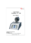
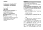
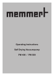
IMPORTANT COMPONENTS IN THE MACHINE
Seal bar
Contra bar / Silicone profile
Lid seal
Oil filling plug
Oil sight glass /
Oil drainage plug
Control panel
Control switch
Vacuum meter
Gas connection
(optional)
(Max 1 Bar)
Main power supply
1
Fuse holder
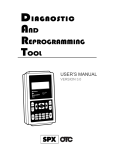
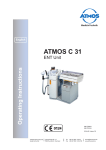
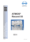
IMPORTANT COMPONENTS IN THE MACHINE
Seal bar
Lid seal
Suction opening
Control panel
Silicone Holder
Vacuum meter
Control switch
Machine plate
Main switch
Oil filling plug
Oil sight glass
Oil drainage plug
2
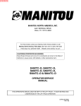
1.0 Technical functions of a vacuum packaging machine:
Vacuum:
Sensor & time control, 10 program
control system
DIGITAL TIME CONTROL
All the machines are equipped with digital controls as standard. These controls allow the
separate programming of the time control of all sub-processes in the packaging process
(vacuum, seal, decompression and possibly gas flush and soft-air). It is also possible to
record the settings of frequently used packaging processes in one of the 9 programs. The
controls are extremely easy to comprehend and simple to operate.
SENSOR CONTROL
With Sensor control, the packaging process is controlled by means of an accurate pressure
sensor. This pressure sensor ensures that the process is finished accurately according to
pressure values, expressed in percentages, programmed in advance. Application of the
pressure sensor ensures consistent packaging results and an optimum cycle time. Sensor
control is normally used in combination with a gas flush system.
SENSOR CONTROL - Vacuum Plus time
Sensor control makes it possible to program an additional vacuum period – vacuum plus
time after reaching the programmed pressure. Vacuum plus time is used to allow the air
trapped in the packaging to escape, thereby creating an optimum vacuum. Vacuum plus
time can only be used when the vacuum sensor pressure has been set to 99%.
SENSOR CONTROL – Time control
A sensor control can also be programmed for normal time control. The sensor will then be
deactivated and the packaging process will be carried out according to the programmed
cycle times.
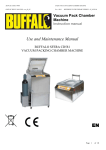
C1
Y2'
Y2
P1
Gas
M1
Y4
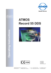
C1 = Seal bag
M1 = Vacuumpump
P1 = Vacuumgauge
Y1 = Vacuum valve
Y2 = Gas valve (optional)
Y2' = Gas valve (optional)
Y3 = Seal valve
Y4 = Softair valve (optional)
Y5 = Devac valve
Y1
Y3
Y5
H600, H675,
Vacuum phase
3
H800
Vacuum:
Quick Stop H2O sensor
During the vacuum cycle, the product can boil and
evaporate despite a cold temperature. The negative
consequences for the shelf life, the general hygiene and
the maintenance of the machine are obvious.
We have invested a lot of effort to put together a sensor
allowing the detection of the « boiling point » of a
product. The evaporation depends of several factors such
as the surrounding pressure, the viscosity and the product
temperature.
Available from the 10 program control system this function
is avoiding unnecessary boiling phases. It permits, among
other:
√ quicker vacuum packing cycles.
√ better protection of the product qualities
(prevention of desiccation, food more juicy…)
√ an appreciable better hygiene as the liquid is not flowing off anymore into the chamber.
√ a better protection of the pump against humidity and corrosion.
The Quickstop H2O sensor is available as a new command system. It is associated with our “classical”
pressure sensor and works in percentage.
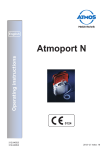
Vacuum:
Fresh Meat program
A special option in the software of the control board ensures a conservation for fresh meats.
This special software diminishes air entrapments (bubbles) in the package and therefore significantly
increases the self life of the product.
By allowing a certain amount of air inside the
chamber directly at the beginning of the sealing
phase, degassing of the meat during the full time of
the sealing phase is prevented.
4
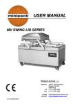
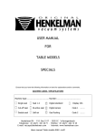
Gas:
Sensor & time control
GAS FLUSH SYSTEM
A gas flush system provides the option to fill the vacuum bag with a quantity of gas
after the termination of the vacuum cycle. This option is frequently used for vulnerable
or fragile products or if the gas provides the product with added value (e.g. product
presentation or storage life).
C1
Y2'
Y2
P1
Gas
M1
Y4
C1 = Seal bag
M1 = Vacuumpump
P1 = Vacuumgauge
Y1 = Vacuum valve
Y2 = Gas valve (optional)
Y2' = Gas valve (optional)
Y3 = Seal valve
Y4 = Softair valve (optional)
Y5 = Devac valve
Y1
Y3
Y5
H600, H675,
Gas flush phase
5
H800
Pressure and volume behavior during the normal vacuum gas flush cycle
Situation 1:
At the end of the vacuum phase the pressure inside the chamber and inside the vacuum bar are equal.
Situation 2:
While gas flushing the volume of the vacuum bag will increase due to an increasing pressure.
The pressure inside the chamber will also rise, but not as quickly as inside the bag.
Situation 3:
At a certain point the volume of the vacuum bag will not increase anymore, and extra gas will be pushed outside
the vacuum bag and inside the chamber. The pressure inside the chamber will increase.
Situation 4:
If the pressure inside the chamber increases and reaches the point where the pressure is equal to the pressure
inside the vacuum bag. At that point the volume of the vacuum bag will decrease.
Situation 5:
The moment we seal the pressure inside the chamber and the vacuum bag is equal.
Situation 6:
The moment we decompress, the volume of the vacuum bag will decrease.
The reduction of the volume will stop when the pressure inside the vacuum bag is equal to the surrounding
atmosphere.
The amount of gas inside the vacuum bag is depending on several issues:
Gas pressure, shape of the product, proportion between size product and the size of the vacuum bag.
If you put a small product in a relative big size of vacuum bag, there is a lot of “free” space, so it is easy
to reach a high volume of gas inside the package.
6
Gas:
Additional gas flush option
With this additional gas flush adjustment we realized two major improvements;
Much better consistency of quality of gas in each package.
It is now possible to create balloon type of packages.
7
Sealing
DOUBLE SEAL
The vacuum bag is sealed with two 3.5 mm concaved wires. The wires used have a rounded
concaved shape. This shape ensures that moisture and dirt on the seal seam is pushed to the
side, closing the packaging cleanly and completely. Two seal wires provide extra security
against rough handling of the packaging during transport and storage.
CUT-OFF SEAL
The vacuum bag is sealed with two wires. The inner seal wire is 3.5 mm wide and has a
rounded concaved shape, and the outer seal wire has a diameter of Ø 1.1 mm. The outer wire
has two functions: this wire creates a narrow seal, and the remaining flap can be torn off
manually due to the fact that the wire almost completely burns through the bag. This provides
optimum product hygiene during transport and storage.
8 mm SEAL
The vacuum bag is sealed with a single flat seal wire, 8 mm wide. This seal system is used
especially for packaging in which presentation is an important factor.
SEAL 1-2
The vacuum bag is sealed with two wires. One wire is 3.5 mm wide with a rounded
concaved shape, and the other wire has a diameter of Ø 1.1 mm. The function of SEAL 12 is the same as the CUT-OFF but provides the option to control the wires separately.
This makes it possible to activate the cut-off wire for longer time than the seal wire. This
modification makes it possible to seal and cut-off almost any type of bag, e.g. shrink
bags.
BI-ACTIVE SEAL
Bi-active seal has a seal wire both on top and bottom. This principle enables seals to be
produced from the bottom and the top simultaneously, with the aim being to produce the
optimum amount of heat in the vacuum bag. This seal system is applied to bags with a
thickness of 200+ mu, or, for example, laminated aluminium bags.
C1
Y2'
Y2
P1
Gas
M1
Y4
C1 = Seal bag
M1 = Vacuumpump
P1 = Vacuumgauge
Y1 = Vacuum valve
Y2 = Gas valve (optional)
Y2' = Gas valve (optional)
Y3 = Seal valve
Y4 = Softair valve (optional)
Y5 = Devac valve
Y1
Y3
Y5
H600, H675,
Sealing phase
8
H800
Sealing cycle step by step
The complete seal activity step by step,
1. pre-seal
(pneumatic action) Default settings for table models 1 second, and
double chambers 2,5 seconds. ( situation 3)
2. actual seal time
(electrical action) settings depending on the thickness and quality of
the vacuum bag ( situation 4)
3. After-seal
( cooling time) Default settings for double chambers 3 seconds.
( situation 5).
During the vacuum process there is a gap (opening) between the top part (seal bar) and lower part
(silicone holder). Through this gap the air inside the vacuum bag can escape.
If the vacuum cycle is finished the seal action will start. It will start with pre-seal.
The explanation of pre-seal:
To start with the electrical sealing we have to close the gap between the top part and lower part, the time
necessary to close the gap we call “pre-seal”. So pre-seal is only the movement of the seal bar.
If the gap is closed (the seal bar is pushed onto the silicone holder), we start the actual sealing time.
Now the seal wires are electrical activated and will heat up.
During the actual sealing time, if the seal bar is resting on the silicone holder, the seal wire can transmit
the generated heat, to the vacuum bag or the silicone profile. For a proper seal, It is essential that all
the generated heat is transmitted to the bag.
After finishing the seal time, we want to make sure that al remaining heat is also transmitted to the bag.
This time we call “after seal time”. For a constant sealing time, specially in case of short vacuum cycles,
it is very important that all generated heat can transfer to the vacuum bags, otherwise the residual heat
(the amount of heat that was not able to transfer to the vacuum bags), will heat up the seal bar itself.
And it is possible that the seal is to hot with the next cycle. If this is happening we recommend to
increase the after seal time.
Due to different circumstances it ma be necessary to change the default settings.
Situation 1: vacuum
Situation 2: gas flush
Situation 3: pre-seal
Situation 4: electrical seal
Situation 5: after-seal
Situation 6: soft-air /
decompression
9
Influence from using gas flush, on seal pressure (1-3)
Table Models
using seal cylinders for seal pressure.
Pomp start and stops every cycle.
C1 = Seal cylinder
M1 = Vacuum pump
P1 = Vacuum gauge
Y2 = Gas valve
Y3 = Seal valve
Y4 = Soft-air valve
Y5 = Decompresion valve
Conclusion:
If using gas flush, seal pressure
decreases with Table Models Machines
10
Influence from using gas flush, on seal pressure (2-3)
Single Chamber Models using seal
cylinders for seal pressure, pump
running constantly.
C1 = Seal cylinder
M1 = Vacuum pump
P1 = Vacuum gauge
Y1 = vacuum valve
Y2 = Gas valve
Y3 = Seal valve
Y4 = Soft-air valve
Y5 = Decompresion valve
Conclusion:
Seal pressure is not dropping if using
gas flush with Single chamber Models
Where the pump is running constantly
11
Influence from using gas flush, on seal pressure (3-3)
Single / Double- chamber Models
using seal bags for seal pressure.
Pump running constantly.
C1 = Seal bag
M1 = Vacuum pump
P1 = Vacuum gauge
Y1 = vacuum valve
Y2 = Gas valve
Y3 = Seal valve
Y4 = Soft-air valve
Y5 = Decompresion valve
Conclusion:
If using gas flush, seal pressure
decreases with Single / Double
chamber Models if equipped with seal
bags.
12
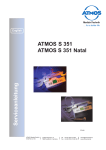
Extra seal pressure
In a certain amount of situations it is possible that the seal pressure is insufficient.
This will show itself by a very irregular and sometimes burned seal.
In this case it is possible to have a special connection for compressed air.(see photo)
One situation where it can occur is, if you use only partial vacuum.
This means if you only pack with 50 % of vacuum.
This also can happen with machines that are equipped with a gas flush option. By using gas flush the
press force for the seal system will drop
accordantly the setting for gas.
So if the setting for gas is 40 %, the actual seal pressure on the
seal bars is also down to 40 %.
Therefore we mount on the different chamber machine, which are
equipped with gas, an extra hose coupling on the backside of the
machine. On this hose coupling it is possible to connect compressed
air (max. 1 bar). With this extra compressed air connection you
re-establish the full press force for the seal system.
A higher pressure will result in a permanent deformation from the
seal system.
Seal pressure behavior form the various machines
Table top models
Pump starts and stops with every cycle, seal pressure is depending on pressure inside
the chamber.
(SV2804TE, SV2808TE, SV3716TE, SV4216TE, SV3516TP, SV4221TP, SV4221TX
and SV4221TB)
Single chambers machines (Equipped with seal cylinders)
Pump Is running continuously, seal pressure is not depending on pressure inside the
chamber.
(SV4663SP, SV5263SP and SV3263SP)
Single chambers machines (Equipped with seal bags)
Pump Is running continuously, seal pressure is depending on pressure inside the
chamber.
(SV5263SA, SV8010SA, SV8063SA, SV5263SS and SV8010SS)
Double chambers machines (Equipped with seal bags)
Pump Is running continuously, seal pressure is depending on
pressure inside the chamber.
(SV4563DA, SV5510DA, SV6263DS, SV6210DS, SV6216DS, SV8430DS
and SV1130DS)
13
Soft-air
SOFT-AIR (slow decompression)
Soft-air is a system that the chamber can be slowly decompressed for a programmable
period following to vacuuming and sealing. The vacuum chamber is decompressed so
slowly that the vacuum bag can shape itself around the product without damaging the
product or the vacuum bag. Soft-air is used primarily for the packaging of soft and/or
vulnerable products (e.g. fish), or products with hard protrusions (e.g. spare ribs).
C1
Y2'
Y2
P1
Gas
Y4
M1
C1 = Seal bag
M1 = Vacuumpump
P1 = Vacuumgauge
Y1 = Vacuum valve
Y2 = Gas valve (optional)
Y2' = Gas valve (optional)
Y3 = Seal valve
Y4 = Softair valve (optional)
Y5 = Devac valve
Y1
Y3
Y5
H600, H675,
Soft-air phase
14
H800
De-compression
DECOMPRESSION)
Decompression is the system that permits the outside air to enter the chamber till
pressure inside the chamber is equal to the outside air, and the lid is opens
automatically.
the
C1
Y2'
Y2
P1
Gas
Y4
M1
C1 = Seal bag
M1 = Vacuumpump
P1 = Vacuumgauge
Y1 = Vacuum valve
Y2 = Gas valve (optional)
Y2' = Gas valve (optional)
Y3 = Seal valve
Y4 = Softair valve (optional)
Y5 = Devac valve
Y1
Y5
Y3
H600, H675,
Decompression phase
15
H800
Extra Functions
Start codes
When starting the machine, first two codes appear on the large display in succession
before control panel switches to operation mode.
The first code indicates the execution / model of the machine.
The second code indicates the control software version.
Service Hours program
The service hours program is a service program which is used for installing a number of
hours after which the panel shows “oil” in the second display, to indicate that the machine
needs service. This program is used as memory to maintain a good and stable service
program for the machine. With help of this option we can prevent that, if settled
correctly, the oil is polluted in a way that it affects the optimal condition of the vacuum
pump.
15 min
Conditioningsprogramme “C” (Special for table Models, but also
necessary in case the sleeper function is activated)
A conditioning program has been included to limit the contamination of the oil caused by
the packaging of damp products (this means products that contain moisture, but also
liquids and sauces).
Regular use of this option will prevent unnecessary oil changes and the possibility of
pump corrosion caused by the excess water in the oil.
External vacuum function “E” (for all Table Models)
External vacuum function is included to make it possible to use special food containers.
The function comes with a special adaptor which should be connected to the vacuum
opening of the machine and suction opening of the food container. The function should be
activated and set through the control panel as well
Sleeper Function (all single and double chamber machines)
Both the standard digital and sensor controls have the possibility to activate a sleeper
function. The sleeper function ensures that the pump switches off after the period
programmed into the sleeper function (while the controls remain active) if the machine is
not in use for a significant period of time. The pump will automatically reactivate when
the machine is used. This function eliminates unnecessary noise pollution caused by the
pump. The sleeper function will only activate after the first cycle has been completed.
It is necessary for the pump to heat up for a minimum of 15 minutes prior to the
packaging in order to allow it to reach its operating temperature.
Machine counter function
The machine counter function registers the use of machine and certain functions for a
solid reference on the state and use of the machine.
Pump operation hours
Total hours which the pump has run.
Machine cycles
Total number of cycles which the machine has run.
Conditioning program cycles
Total number of cycles which the pump conditioning program
has run.
Service detection (gate test function)
The service detection function can help you to check whether a certain selected function
will working properly. This is convenient when the machine has a problem and the
technician has not idea yet where might be the cause of the problem.
With the help of this mode all function of the machine can be tested not only electrically
But on there full function.
16
Special option for Stainless steel swing lids.
Volume reduction by Lid filler plates.
Due to the volume reduction the cycle time shortens with 15-20 % and saving a gas consumption of
10-12 %!
Calculation the savings on gas the gas consumption: the pay-back time is approx 2 month!.
These filler plates are available for all stainless steel swing lids. The material of the filler plates is in
compliance with the European Directive for Food contact 90/128/EEC and its amendments. This means it
is allowed for utilization in the food processing equipment.
17
Time / Function Diagram.
Table models (10 program control)
Active cycle start the moment the lid is closed and the micro switch is activated.
Pump start to run, and the digital control is counting.
No vacuum valve mounted ( the non return valve inside the vacuum pump is taking over this function)
If vacuum time is ended, the pump stops.
Now the gas function is active, “T2”.
After ending the gas time the seal function is started.
The seal function is divided into two separate actions. The pneumatic part: activating “U4”
(moving of the seal bar)
The electric part: activating the seal contactor “U5”. (heating up the seal bar).
“T3” is the seal time, the setting is depending on the thickness and the quality of the vacuum bag
C1
U1
T1
U3
T2
U4
U5
T3
The time “TA”, after activating the seal valve “U4” but before activating “U5” contactor sealing, is called pre-seal time.
This is the time necessary to move the seal system against the counter bar.
The time “TB”, after ending the seal time “ T3” but before activating “U6” soft-air valve, is called cool time.
This is the time necessary to transmit the generated heat to the vacuum bags.
Now the soft-air function “U6” is activated
“T4”is the soft-air time, the setting is depending on the product.
And finally the decompression valve “U7” is activated till the lid is open, and the micro switch is de-activated.
18
U6
T4
U7
Time / Function Diagram.
The moment the machine is activated, the pump start to run.
Active cycle start the moment the lid is closed and the micro switch is activated.
The vacuum valve is activated, and the digital control is counting.
If vacuum time is ended, the vacuum valve is de-activated. The pump is still running.
Now the gas function is active, “T2”.
After ending the gas time the seal function is started.
The seal function is divided into two separate actions. The pneumatic part: activating “U4”
(moving of the seal bar)
The electric part: activating the seal contactor “U5”. (heating up the seal bar).
“T3” is the seal time, the setting is depending on the thickness and the quality of the vacuum bag
U1
C1
U2
T1
U3
T2
U4
U5
T3
The time “TA”, after activating the seal valve “U4” but before activating “U5” contactor sealing, is called pre-seal time.
This is the time necessary to move the seal system against the counter bar.
The time “TB”, after ending the seal time “ T3” but before activating “U6” soft-air valve, is called cool time.
This is the time necessary to transmit the generated heat to the vacuum bags.
Now the soft-air function “U6” is activated
“T4”is the soft-air time, the setting is depending on the product.
And finally the decompression valve “U7” is activated till the lid is open, and the micro switch is de-activated.
19
U6
T4
U7
ELECTRICAL DIAGRAMS
We have divided the electrical diagrams into a main current and a control diagrams.
Control diagram SV4221TP model:
Main current diagram SV4221TP (230 Volt – 1 ~ ):
20
ELECTRICAL DIAGRAMS
We have divided the electrical diagrams into a main current and control current diagrams.
Control diagram SV6216DS model:
Double chamber Main current diagram SV6216DS (400 Volt – 3~)
21
DIGITAL CONTROL
S
Siinnggllee pprrooggrraam
m ccoonnttrrooll ssyysstteem
m
CONTROL PANEL VERSION
Digital time control
The digital control is implemented with a function program that can be set with different
function values per cycle (to be able to pack different products). A program cycle is the
complete program of set functions (vacuum and seal) that the machine runs through to
package a product.
The control panel is implemented standard with a conditioning program for the regular
maintenance of the pump and two STOP keys for complete function interruption or for only
active function interruption. There are also a number of built-in service programs. Contact
South Coast Systems for more information about these functions.
The value of the functions can be set for a certain time period.
The vacuum function can be set to whole seconds with a maximum of 99 seconds.
The seal function can be set with an interval of 0.1 seconds and a maximum of 6.0 seconds.
CONTROL PANEL LAY-OUT
2
8
3
1
5
7
4
6
4
1. Display
Displays the status of the active function during the run of the program cycle or the set value of the selected function
when machine is not running.
2. FUNCTION SELECTION Key
Select function (vacuum or seal) for viewing or changing function values. The function is selected if the function light is
on in front of the function description under the display.
3. CONDITIONING PROGRAMME Key
Start the conditioning program for pump (duration 15 minutes). For instructions on the program, see page 15.
4. FUNCTION Lights
A light in front of the function indicates that the function is active during the program cycle or that the function is
selected for view or change.
22
5. + / STOP VACUUM Key
Function during cycle
General function.
6. - / STOP Key
Function during cycle
General function
Interruption of the active function during the program cycle. The cycle immediately
continues with the next function.
Increment the value of the selected function.
Terminates the program cycle completely. The cycle immediately switches into the
ventilation function.
Decrement the value of the selected function.
7. Vacuum meter
Displays the pressure in the vacuum chamber.
8. ON/OFF Switch
The ON/OFF switch is used to turn the machine on and off before and after operation. The switch turns on all units in
the machine. Caution, the switch does not completely remove all power from the machine.
CONTROL PANEL USE
When the machine is turned on then the it is ready for use once the two operating codes have displayed.
Description of the program cycle for digital time control
1. Functions (vacuum and sealing) are set with the correct values
2. Close the lid.
3. Vacuum function
The machine starts to vacuum the chamber.
The light in front of [VACUUM] goes on.
Display : decrementing time per second starting at the time set (max. 99 sec.).
Vacuum meter starts increasing to the left.
4. Sealing function
Once the vacuum function is finished, the sealing function starts to seal the vacuum bag(s).
The light in front of [SEAL] goes on.
Display : decrementing time per 0.1 second starting at the time set (max. 6.0 sec.).
The reading on the vacuum meter stays the same.
5. Ventilating function
After ending the seal function the ventilating function starts ventilating the chamber to 1
atmosphere/ATO and the lid opens.
There are no longer any lights on in front of the functions.
Display : lines moving up and down until the lid is opened.
The vacuum meter runs back to the right to zero and the lid opens automatically.
6. The product is packed and ready to remove.
23
Set / change function values
The following steps must be followed to change the function values for vacuum and/or seal :
Press the FUNCTION SELECT Key to select the required function. The function light will light up when the function is
selected.
Press the [+ / STOP VACUUM] or [- / STOP] keys for incrementing or decrementing the function values respectively. It
takes 0.5 seconds before the value begins to change.
After changing the value(s) the machine must run through the cycle once (see previous page) to record the values.
Vacuum function
The vacuum function value can be incremented or decremented per second with a maximum of 99 seconds and a
minimum of 2 seconds.
If while changing the vacuum function setting the [+ / STOP VACUUM] or [- / STOP] key is held down then the first 5
seconds will be incremented or decremented per second. Then intervals of 10 seconds will appear. If the key is
released then the settings can be changed again per second.
Sealing function
The seal function setting can be increased or decreased with a maximum of 6.0 sec. and a minimum of 0.5 sec.
If while changing the vacuum function setting the [+ / STOP VACUUM] or [- / STOP] key is held down then the first 0.5
seconds will be incremented or decremented per 0.1 second. Then intervals of 1.0 second will appear. If the key is
released then the settings can be changed again per 0.1 second.
START CODES
Service hours
counter
Additional service
indicator 120
hours
External vacuum
X
X
X
X
X
X
X
X
X
Display code
00
02
08
06
10
14
24
SERVICE MODE – PUMP CONDITIONING PROGRAM
The conditioning program ensures that the pump is thoroughly rinsed. During the program the pump
and oil reaches operation temperature so that the oil can better absorb any moisture and
contaminants and filter them. The high temperature enables any moisture in the pump to evaporate
minimising the risk for rust spots.
The program lasts 15 minutes and it is advisable to run it at least once a week. Turn on the machine, press the key
[conditioning program], and close the lid. The program runs automatically. During the program the large display will
display moving lines.
The program can be interrupted at any time using the [STOP] key. It is however important for the sake of good
maintenance that the program completes a full 15 minute cycle and therefore advisable only to interrupt the cycle for
something urgent.
It is also advisable to run the program before using the machine for the first time, after the machine has been
stationary for a lengthy period of time, and especially prior to changing oil.
25
SERVICE MODE – SERVICE HOURS COUNTER FUNCTION
The service hours counter function is used for setting time intervals (per 10 hours) for regular maintenance purposes on
machine and/or pump.
After expiration of set time interval, the control panel will provide the signal { OIL } that the interval
has expired and maintenance can be done. Signal disappears after 3 seconds and machine can
be used. However, signal is coming back each time when machine is started up.
Pay attention that the function only counts the hours that the pump is running (so only cycle times).
Standard factory setting function is OFF position.
ACTIVATE SERVICE HOURS COUNTER FUNCTION
1. Machine is OFF
2. Push [ + | VACUUM STOP ] , [ - | STOP ] and
[ SELECTION ] button and turn on machine while
pushing these buttons.
3. Keep pushing the buttons for at least 2 seconds
until { 6 o } appears on screen. Release buttons after
appearance of { 6 o } which is the number for service
hours counter program.
+
VACUUM
STOP
STOP
Enter service program activation mode
+
VACUUM
STOP
Activate function
4. Push [ + | VACUUM STOP ] button for activation program.
Signal { 6 I } appears now in display. This indicates that the
program has been activated. For de-activation push [ - | STOP ]
button.
5. For storing the activation, close the lid.
SET SERVICE HOURS COUNTER FUNCTION
Enter program mode
+
VACUUM
STOP
When function has been activated, the service hours can
be set as follows :
1. Machine is ON. Push [ SELECTION ] button for at least 5
seconds. After 5 seconds, the consumed hours (per 10
hours) appear for three seconds before displaying the set
service hours (standard setting is 12 which indicates 120
hours).
2. Push [ + | VACUUM STOP ] or [ - | STOP ] buttons to
increase or decrease the set value (per 10 hours).
STOP
Change value
Store value
3. Storing the value will be done by pushing the
[ SELECTION ] button once again.
26
SERVICE MODE – ADDITIONAL SERVICE INDICATOR FUNCTION
This additional service indicator is mend to help the customers to use the conditionings program.
After expiration of default time of 120 hours, the control panel will provide the signal , a flashing “C”.
This indicates preset time has expired and pump conditionings program should be used.(reed more about
conditioning program on page 25)
If the operator wishes to use the pump conditionings program, he should press the special
button.
By pressing the function key, the control will return to the standard program mode.
But next time the machine is activated, the flashing “C” will appear again as reminder.
Once one complete pump conditioning cycle is completed, the counter will be reset.
Standard factory setting function is OFF position.
ACTIVATE ADDITIONAL SERVICE INDICATOR FUNCTION
+
VACUUM
STOP
STOP
Enter service program activation mode
+
VACUUM
STOP
Activate function
1. Machine is OFF
2. Push [ + | VACUUM STOP ] , [ - | STOP ] and
[ SELECTION ] button and turn on machine
while pushing these buttons.
3. Keep pushing the buttons for at least 2
seconds until { 7 o } appears on screen.
Release buttons after appearance of {7 o }
which is the number for service hours counter
program.
4. Push [ + | VACUUM STOP ] button for activation program.
Signal { 7 I } appears now in display. This indicates that the
program has been activated. For de-activation push [ - |
STOP ] button.
5. For storing the activation, close the lid.
6. The default factory setting is 120 hours and is not changeable.
27
SERVICE MODE – SERVICE DETECTION (GATE TEST) FUNCTION
The service detection function can detect whether certain selected parts will be activated during operation or not. This
is convenient when the machine has a problem and the technician has not idea yet where might be the cause of the
problem.
ACTIVATE AND USE SERVICE DETECTION FUNCTION
+
VACUUM
STOP
STOP
Enter SERVICE DETECTION function mode
1. Machine is OFF.
2. Push [ + | VACUUM STOP ] or [ - | STOP ] buttons at same
time and turn on machine with ON/OFF switch while pushing
buttons.
3. Keep pushing both buttons for at least 5 seconds. First the
starting codes appear and after 5 seconds { 1 o } appears in
large display. { 1 o } indicates part 1 in OFF position.
+
VACUUM
STOP
4. Push [ + | VACUUM STOP ] button to activate the selected
part . Push [ - | STOP ] button to de-activate the selected part.
When the part is physically activated and de-activated (you
hear a click).
STOP
Activate detection part
1
2
3
4
5
Pump relay
Seal valve
Seal relay
No function
Ventilation valve
Selection parts
Return to operation mode
5. Push SELECTOR button to select part no. which is required
to be detected. See list of part no. in overview. Please pay
attention that for part numbers 3, the maximum activation time
is 3 seconds. Longer activation time will result in burns on
sealing bar or other relevant parts.
6. Switch off and turn on machine again to return to operation
mode.
28
SERVICE MODE – FACTORY SETTINGS FUNCTION
The factory settings function is used for returning all values and settings (operation mode and service mode) in the
control panel to the original factory setting.
ACTIVATE AND SET FACTORY SETTINGS FUNCTION
1. Machine is OFF.
2. Push SELECTOR button and turn on machine with ON/OFF
switch while pushing button.
3. Keep pushing button for at least 5 seconds. First the starting
codes appear and after control panel is returned to factory
settings/3 seconds { rP } appears in large display.
4. Release SELECTOR button and control panel returns
automatically all values and setting to original factory settings.
ERROR CODES
F1=
De-activation of micro switch during cycle run.
29
SPECIAL OPTION - EXTERNAL VACUUM FUNCTION (only available for Table Models)
External vacuum function is used for vacuuming special food containers. The function comes with a special adaptor
which should be connected to the vacuum opening of the machine and suction opening of the food container. The
function should be activated and set through the control panel as well. See operation procedures in user manual. See
for setting and activation procedures below :
ACTIVATE EXTERNAL VACUUM FUNCTION
1. Machine is OFF
2. Push [ + | VACUUM STOP ] , [ - | STOP ] and
[ SELECTION ] button and turn on machine while
pushing these buttons.
3. Keep pushing the buttons for at least 2 seconds
until { 6 o } appears on screen. Release buttons
after appearance of { 6 o } which is the number for
+
VACUUM
STOP
STOP
Enter service program activation mode
service hours counter program.
4. Push [ SELECTION ] button twice for appearance of { 8 o }
on screen which is the number for external vacuum option.
Activate function
+
VACUUM
STOP
Activate function
5. Push [ + | VACUUM STOP ] button for activation program.
Signal { 7 I } appears now in display. This indicates that the
program has been activated. For de-activation push [ - | STOP ]
button.
6. For storing the activation, close the lid.
USE EXTERNAL VACUUM FUNCTION
EXTERNAL VACUUM function can be selected in operation mode through
pushing button [ CONDITIONING PROGRAM ].
appears in display.
Subsequently, push button [SELECTION ]
appears in display.
E stands for “external vacuum”.
External vacuum is now ready for use.
+
VACUUM
STOP
To active the function push
To de-activate push the
STOP
and the pump start to run (max. for 15 min).
button and the pump stops.
30
SERVICE MODE – MACHINE COUNTER FUNCTION
The machine counter function registers the use of machine and certain functions for a solid reference on the state and
use of the machine. Total hours which the pump has run, total number of cycles which the machine has run, and total
number of cycles which the pump conditioning program has run will be displayed in the function.
ACTIVATE MACHINE COUNTER FUNCTION
1. Machine is OFF.
2. Push SELECTOR and
CONDITIONING PROGRAM
buttons at same time and turn on
machine with ON/OFF switch while
pushing buttons.
3. Keep pushing for at least 5 seconds.
First the starting codes appear and
after 5 seconds { co } appears in large
display.
4. Release buttons, after 5 seconds the
control panel displays subsequently
machine hours (per 10 hours) which
the machine has run, number of cycles
(per 100 cycles) which the machine
has run, and last the number of cycles
which the conditioning program has
run. The three indications appear each
for 2 seconds in display.
5. After that the control panel
automatically returns to the standard
operation mode.
Enter MACHINE COUNTER function mode
Pump operation
hours (per 10 hours)
Machine cycles
(per 100 Cycles)
Conditioning program
cycles
Display counters
The values cannot be deleted. When the values reach 99, it returns automatically to 0 and starts again.
31
DIGITAL CONTROL
1100 pprrooggrraam
m ccoonnttrrooll ssyysstteem
m
CONTROL PANEL VERSIONS
General
The digital control panels are implemented with 9 pre-select programs that can be
individually set with different function values (to be able to pack different products) Program
0 can not be set and is used for servicing and testing. A program cycle is the complete
program of set functions that the machine runs through to package a product.
The control panels are designed with a operation mode and a program mode.
The operation mode is used during operational activities for selecting the program number
with the required program cycle. The set values of the function program can also be seen in
the operation mode but not changed.
The program mode is used to change the function values within the programs.
The control panels are implemented standard with an automatic conditioning program for
the regular maintenance of the pump and two STOP keys for complete cycle interruption or
for only active function interruption. There are also a number of built-in service programs.
Contact South Coast Systems for more information about these programs.
Digital Time Control
The value of all active functions can be set for a certain time period.
The vacuum function, gas flush function (if installed), and soft air function can be set in
whole seconds up to a maximum of 99 seconds.
The seal function can be set with an interval of 0.1 seconds and a maximum of 6.0 seconds.
32
Digital Sensor Control
The value of the vacuum function and the gas flush function (if installed) can be set as a
percentage of the vacuum. This is the percentage of the under pressure in the vacuum
chamber related to the outside pressure 1 atmosphere/ATO (0%).
The maximum vacuum percentage setting of the vacuum function is 99%.
The minimum vacuum percentage setting of the gas flush function is 30%. This means that
the chamber is flushed with gas to 30% under pressure in relation to 1 atmosphere. It is
often expressed as 70% is flushed with gas (99+% - 30% = 70%).
The time for the soft air function can be set on whole seconds (max. 99 seconds).
The time for the seal function can be set on 0.1 seconds (max. 6.0 seconds).
The digital sensor control comes standard with the VACUUM PLUS function. The VACUUM
PLUS function is a time operated additional vacuum function for setting extra time after
reaching the 99% value of the vacuum function (only applicable if 99% is set for the vacuum
function). This function provides additional vacuum time for vacuuming any trapped air out
of the package.
Digital Multi-cycle Option The digital multi-cycle control is a special option on the digital time control for running more
vacuum and gas flush or rest sub-cycles continuous before going to seal function. The
control is useful for packaging applications which require a very low rest-oxygen in the
package or which requires rest times between vacuum to let the air out of the package or
product. The maximum number of vacuum-gas flush (or rest) sub-cycles before proceeding
to seal function is five. The value specifications of the option is the same to the digital time
control. For activating and setting the multi-cycle option, please review on page 47.
CONTROL PANEL LAY-OUT
1
2
3
5
4
6
7
7
7
7
10
8
9
11
1. Small Display
Displays active program in operating and program modes.
2. Large Display
Displays the current value of the active function during the program cycle or the set value of the selected function in
operation or program mode.
3. PROG 0-9 Key
Selects program number in operation or program mode.
4. REPROG Key
Switch from operation mode to program mode (for setting function values) and vice versa. After setting new function
value(s) within a selected program in program mode, this key must always be used to store the new values for the
program in memory.
5. FUNCTION SELECT Key
Selects function within selected program in operation and program mode. The function is selected if the function light is
on in front of the function description under the large display.
33
6. CONDITIONING PROGRAM Key
Start the conditioning program for pump (duration 15 minutes). For instructions on the program, see page 36.
7. FUNCTION Lights
A light in front of the function indicates that the function is active during the program cycle or that the function is
selected during the operation or program modes.
Special Remark
There is an additional time operated vacuum function available at digital sensor control, the VACUUM
PLUS function. This function is not displayed on the panel. The VACUUM PLUS function can only be
activated if the standard vacuum function is set to 99%
VACUUM PLUS function display during the cycle (if activated) : The vacuum indicator light remains
on after 99% is reached and during the time set for VACUUM PLUS. During the VACUUM PLUS
vacuum cycle a dot appears in the right lower corner of the large display.
Display during operation and program mode : If the VACUUM PLUS time is activated during the
selected program then a dot appears in the lower right-hand corner of the large display during the
operation and program mode. If the functions are selected using the function selection keys then the
indicator light in front of VACUUM comes on twice, and the vacuum percentage and VACUUM PLUS
time are shown consecutively.
Special Remark
If the machine has the gas flush function implemented and the function is activated within the
selected program then a dot appears in the lower right hand corner of the small display when
selecting the program no..
8. + / STOP VACUUM Key
Function during cycle
Function in program mode
9. - / STOP Key
Function during cycle
Function in program mode
Interruption of the active function during the program cycle. The cycle immediately
continues with the next function.
Raise the value of the selected function within the program selected in the program
mode.
Terminates the program cycle completely. The cycle immediately switches to the
ventilation function.
Lower the value of the selected function within the program selected in the program
mode.
10. Vacuum meter
Displays the pressure in the vacuum chamber. See the following table for the relationship between the vacuum meter
and the percentage vacuum.
Position
vacuum meter
0
0.2
0.3
0.4
0.5
0.6
0.7
0.8
0.9
- 1.0
Vacuum
percentage
0
20
30
40
50
60
70
80
90
99+
11. ON/OFF Switch
The ON/OFF switch is used to turn the machine on and off before and after operation. The switch turns on the control
panel for operating the machine. Caution, the switch does not completely remove all power from the machine.
34
DIPSWITCH SETTINGS / STARTING CODES
The dipswitches on the printed circuit board are to be used to activate several (optional) functions on the control.
ON POSITION
1
2
3
4
5
6
7
8
ACTIVATION
Multi-cycle control
Continuous pump running
Pre-seal factory setting 1.0 seconds / After-seal factory setting 2.5 seconds
Pump conditioning program on separate conditioning program button
Soft air ventilation
1-2 Cut off seal (separate time settings for seal and cut)
Gas flush injection function
Digital sensor control function
Quick Stop H2O Sensor
35
SERVICE MODE – PUMP CONDITIONING PROGRAM
The conditioning program ensures that the pump is thoroughly rinsed. During the program the pump
and oil reaches operation temperature so that the oil can better absorb any moisture and
contaminants and filter them. The high temperature enables any moisture in the pump to evaporate
minimising the risk for rust spots.
The program lasts 15 minutes and it is advisable to run it at least once a week. Turn on the machine, press the key
[conditioning program], and close the lid. The program runs automatically. During the program the large display will
display moving lines.
The program can be interrupted at any time using the [STOP] key. It is however important for the sake of good
maintenance that the program completes a full 15 minute cycle and therefore advisable only to interrupt the cycle for
something urgent.
It is also advisable to run the program before using the machine for the first time, after the machine has been stationary for a
lengthy period of time, and especially prior to changing oil.
36
SERVICE MODE - SLEEPER TIME FUNCTION
Sleeper time function is used for automatic stop of vacuum pump running after set time in sleeper time function when
machines has not been used during the set time.
When machine is used again by closing the lid, the vacuum pump starts automatically running again.
Sleeper time function is only useful when dilswitch (continuous pump running) is ON.
Standard factory setting function is OFF position.
ACTIVATE AND SET SLEEPER TIME FUNCTION
+
VACUUM
STOP
1. Machine is off
2. Push [ FUNCTION SELECTION ] button and [ + | VACUUM
STOP ] buttons at same time and turn on machine with
ON/OFF switch while pushing buttons.
3. Keep pushing both buttons for at least 5 seconds. First the
starting codes appear and after 5 seconds { SL o } appears in
large display. { SL o } indicates sleeper function in OFF
position.
4. Release buttons
+
5. Push [ + | VACUUM STOP ] button once and { SL o }
changes to { SL I }. This means sleeper function is activated.
VACUUM
STOP
Enter SLEEPER TIME function mode
6. Push [ FUNCTION SELECTION ] button and { 001 } appears
in screen. This indicates the time interval for the sleeper
Activate SLEEPER TIME function
after 6 seconds not using the machine, the pump stops
running.
+
VACUUM
STOP
function. The time interval is 6 seconds so { 001 } means that
STOP
Go to SLEEPER TIME value
7. Push [ + | VACUUM STOP ] or [ - | STOP ] buttons to
increase or decrease the number of time intervals with a
minimum of { 001 } which is 6 seconds and a maximum of {
099 } which is 5.994 seconds (appr. 10 minutes)
REPROG
Set required SLEEPER TIME
8. After setting the desired time interval, push [ REPROG ]
button to store activation and setting. Control panel returns automatically to standard operation mode.
37
SERVICE MODE – SERVICE HOURS COUNTER FUNCTION
The service hours counter function is used for setting time intervals (per 10 hours) for regular maintenance purposes
on machine and/or pump.
After expiration of set time interval, the control panel will provide the signal { OIL } that the
interval has expired and maintenance can be done. Machine can still be used for normal
operation after appearance but the signal keeps coming back.
Moreover, the function also displays the already consumed hours within the set time interval.
Pay attention that the function only counts the hours that the pump is running. So when the pump is not running
continuously (BOXER series), the counter only counts the time that the pump is running (vacuum function).
Standard factory setting function is OFF position.
ACTIVATE AND SET SERVICE HOURS COUNTER FUNCTION
Enter COUNTER function mode
+
VACUUM
STOP
STOP
Activate and or set COUNTER function
REPROG
Store activation and/or settings
1. Machine is ON
2. Push [ FUNCTION SELECTION ] button for at least 3
seconds.
3. After 3 seconds, the already consumed time (per 10
hours) will appear on display for 2 seconds (value
between 0 and 99). After display switches to originally
set service hours interval (per 10 hours). When function
has not been activated, there will be no appearance of
already consumed time and OFF will appear on display
after 3 seconds.
4. Push [ + | VACUUM STOP ] or [ - | STOP ] buttons to
activate and/or reset the required service hours interval.
The number on the display reflects 10 hours of
operation. So minimum value 1 indicates 10 hours and
maximum 99 means 990 hours. When set to value 0,
this means that the function will be de-activated (next
time when function mode is entered, OFF will appear on
display).
5. Push REPROG button to store new value in function.
Consumed hours will also be reset by this procedure.
Control panel will return automatically to operation mode.
38
SERVICE MODE – SERVICE DETECTION (GATE TEST) FUNCTION
The service detection function can detect whether certain selected parts will be activated during operation or not. This
is convenient when the machine has a problem and the technician has not idea yet where might be the cause of the
problem.
ACTIVATE AND USE SERVICE DETECTION FUNCTION
1. Machine is OFF.
2. Push [ + | VACUUM STOP ] and [ - | STOP ] buttons at
same time and turn on machine with ON/OFF switch
while pushing buttons.
3. Keep pushing both buttons for at least 5 seconds. First
the starting codes appear and after 5 seconds { 1 o }
appears in large display. { 1 o } indicates part 1 in OFF
position.
+
VACUUM
STOP
STOP
Enter SERVICE DETECTION function mode
+
4. Push [ + | VACUUM STOP ] button to activate the
selected part . Push [ - | STOP ] button to de-activate
the selected part. When the part is physically activated
and de-activated (you hear a click).
VACUUM
STOP
STOP
Activate detection part
1.
2.
3.
4.
5.
Pump
Vacuum valve
Gas valve
Seal valve
Magnetic switch seal 1
(activation max. 3 sec. !!)
6. Magnetic switch seal 2
(activation max. 3 sec. !!)
7. Soft air valve
8. Decompression valve
5. Push SELECTOR button to select part no. which is
required to be detected. See list of part no. in overview.
Please pay attention that for part numbers 5 or 6, the
maximum activation time is 3 seconds. Longer activation
time will result in burns on sealing bar or other relevant
parts.
Selection parts
REPROG
Return to operation mode
6. Push REPROG button to return to operation mode.
39
SERVICE MODE – FACTORY SETTINGS FUNCTION
The factory settings function is used for returning all values and settings (operation mode and service mode) in the
control panel to the original factory setting.
ACTIVATE FACTORY SETTINGS FUNCTION
Enter FACTORY SETTINGS function mode
1. Machine is OFF.
2. Push SELECTOR button and turn on machine with
ON/OFF switch while pushing button.
3. Keep pushing button for at least 3 seconds. First the
starting codes appear and after 3 seconds { rP } appears
in large display.
4. Release SELECTOR button and control panel returns
automatically all values and setting to original factory
settings. Only machine counter values (see next page)
remain on present value.
40
SERVICE MODE – MACHINE COUNTER FUNCTION
The machine counter function registers the use of machine and certain functions for a solid reference on the state and
use of the machine. Total hours which the pump has run, total number of cycles which the machine has run, and total
number of cycles which the pump conditioning program has run will be displayed in the function.
ACTIVATE MACHINE COUNTER FUNCTION
Enter MACHINE COUNTER function mode
Pump operation
hours (per 10 hours)
Machine cycles
(per 100 Cycles)
Conditioning program
cycles
1. Machine is OFF.
2. Push SELECTOR and CONDITIONING PROGRAM buttons at
same time and turn on machine with ON/OFF switch while
pushing buttons.
3. Keep pushing button for at least 5 seconds. First the starting
codes appear and after 5 seconds { co } appears in large
display.
4. Release buttons and after 5 seconds control panel displays
subsequently machine hours (per 10 hours) which the machine
has run, number of cycles (per 100 cycles) which the machine
has run, and last the number of cycles which the conditioning
program has run. The three indications appear each for 2
seconds in display.
5. After control panel return automatically to standard operation
mode.
The values cannot be deleted. When the values reach 99, it returns
automatically to 0 and starts again.
Display counters
41
SERVICE MODE – REPEATING PROGRAM FUNCTION
The repeating program function is used for continuously repeating a program for testing whether problems would arise
when machine is running for longer time.
ACTIVATE REPEATING PROGRAM FUNCTION
+
VACUUM
STOP
STOP
Only for Henkelman
purpose
PROG
0-9
1. Machine is OFF.
2. Push [ + | VACUUM STOP ] , [ - | STOP ] and SELECTOR
buttons at same time and turn on machine with ON/OFF
switch while pushing buttons.
3. Keep pushing button for at least 5 seconds. First the starting
codes appear and after 5 seconds { tPO } appears in large
display. This function is only for Henkelman internal purposes.
4. Push [ PROG 0-9 ] button once and mode changes to
REPEATING PROGRAM function mode. { tPO } changes to
{ rPt }.
5. Close the lid and the program which has been selected in
operation mode will start running continuously.
Enter REPEATING PROGRAM function mode
STOP
STOP continuous
repeating program
Return to operation mode
6. Push [ - | STOP ] button to interrupt the function and push
[ REPROG ] button to return to operation mode.
7. Push [ REPROG ] button for returning to operation mode
REPROG
42
SERVICE MODE – PRE-SEAL AND AFTER-SEAL FUNCTION
The pre-seal and after-seal function enables to change the time settings for pre-seal and after-seal.
ACTIVATE PRE-SEAL AND AFTER-SEAL FUNCTION
+
VACUUM
STOP
STOP
Only for Henkelman
purpose
PROG
0-9
1. Machine is OFF.
2. Push [ + | VACUUM STOP ] , [ - | STOP ] and SELECTOR
buttons at same time and turn on machine with ON/OFF switch
while pushing buttons.
3. Keep pushing button for at least 5 seconds. First the starting
codes appear and after 5 seconds { tPO } appears in large
display. This function is only for Henkelman internal purposes.
4. Push [ PROG 0-9 ] button twice and mode changes to PRESEAL function mode, {1 1,0 }. The first value 1 indicates preseal mode. The second value 1,0 indicates the pre-seal time.
5. Push [ PROG 0-9 ] button once more and mode changes to
AFTER-SEAL function mode, {2 3,0 }. The first value 2
indicates after-seal mode. The second value 3,0 indicates the
after-seal time.
PROG
0-9
Enter pre-seal function mode
PROG
0-9
Enter after-seal function mode
Change time values
pre-seal or after-seal
+
VACUUM
STOP
REPROG
6. Change time settings by using [ + | VACUUM STOP ] and
[ - | STOP ] buttons when selected either mode.
STOP
Store values and return to
operation mode
7. When settings have been changed upon required time, push [
REPROG ] button to store new values and return to operation
mode.
43
SERVICE MODE – SENSOR CALIBRATION FUNCTION
The sensor calibration function sets the right pressure values to the corresponding vacuum percentage values. For this
calibrating the sensor function, a digital vacuum meter is required
ACTIVATE SENSOR CALIBRATION FUNCTION
+
VACUUM
STOP
STOP
Only for Henkelman
purpose
PROG
0-9
1. Machine is OFF.
2. Push [ + | VACUUM STOP ] , [ - | STOP ] and SELECTOR
buttons at same time and turn on machine with ON/OFF switch
while pushing buttons.
3. Keep pushing button for at least 5 seconds. First the starting
codes appear and after 5 seconds { tPO } appears in large
display. This function is only for Henkelman internal purposes.
4. Push [ PROG 0-9 ] button 4 times for entering the
CALIBRATION function , { CAL }.
5. Place digital vacuum meter in chamber.
PROG
0-9
PROG
0-9
PROG
0-9
Enter calibration function mode
+
VACUUM
STOP
STOP
REPROG
Set 0% value which is
1 Bar
Set 99% value which is
8-10 mBar
Store values and return to
operation mode
6. Push [ + | VACUUM STOP ] button for setting the 0% vacuum
value (which is 1 Bar).
7. Close the lid and keep it closed while pushing [ - | STOP ]
button. The pump starts to run now. Keep pushing the
[ - | STOP ] button until the digital vacuum meter shows appr.
8-10 mBar.
8. Release [ - | STOP ] button. This is the setting for 99% vacuum
value.
9. Push [ REPROG ] button to store new values and return to
operation mode.
44
ERROR CODES
F1=
De-activation of micros witch during cycle run. For example when gas flush function is set at a too high value
and lid opens.
F2=
For sensor control panel. Starting pressure is not equal to set start pressure of sensor. For example, when
there is a tube bended and still vacuum (low pressure) in the system.
45
SPECIAL OPTION - EXTERNAL VACUUM FUNCTION (only available for Table Models)
External vacuum function is used for vacuuming special food containers. The function comes with a special adaptor
which should be connected to the vacuum opening of the machine and suction opening of the food container. The
function should be activated and set through the control panel as well. See operation procedures in user manual. See
for setting and activation procedures below :
ACTIVATE AND SET EXTERNAL VACUUM FUNCTION
+
VACUUM
STOP
PROG
0-9
Select EXTERNAL VACUUM function mode
1. Machine is off
2. Push [ FUNCTION SELECTION ] button and [ + | VACUUM
STOP ] button at same time and turn on machine with
ON/OFF switch while pushing buttons.
3. Keep pushing both buttons for at least 5 seconds. First the
starting codes appear and after 5 seconds { SL o } appears in
large display. This is the SLEEPER TIME function mode.
4. Release buttons
5. Push [ PROG 0-9 ] button once and mode changes to
EXTERNAL VACUUM function mode. { SL o } changes to { E o }.
6. Push [ + | VACUUM STOP ] button once and and { E o }
changes to { E I }. This means EXTERNAL VACUUM function
is activated.
+
VACUUM
STOP
Activate EXTERNAL VACUUM function
7. Push [ REPROG ] button for storing the activation of
function.
8. Control panel returns automatically to operation mode.
REPROG
Store activation
EXTERNAL VACUUM function can be selected in operation mode through button [ PROG 0-9 ] until { E } appears in
small display.
46
SPECIAL OPTION – MULTI-CYCLE CONTROL FUNCTION
The multi-cycle control option is used for packaging applications which require very low oxygen rests in package. The
operation mode cycle of the multi-cycle control is automatically repeating vacuum and gas flush functions with a
maximum of five times before proceeding to seal function.
The repetition of the vacuum and gas flush functions results in an optimum reduction of oxygen rests because during
each repetition the oxygen rests mix with gas and being then vacuumed again. So the oxygen percentage left in
package is reduced to minimum.
Special note :
For normal industrial or retail applications, the multi-cycle control does not create any considerable benefits
for the package or product shelf life. The vacuum achieved with normal controls are more than sufficient.
Multi-cycle control is only used for highly special laboratory or product applications.
MASTER CYCLE MULTI-CYCLE CONTROL
Vacuum function 1 ► Gas flush function 1 ► Vacuum function 2 ►Gas flush function 2 ►
Vacuum function 3 ► Gas flush function 3 ► Vacuum function 4 ►Gas flush function 4 ►
Vacuum function 5 ►Gas flush function 5 ►
Sealfunction ►Soft air ventilation function ►Ventilation function
For setting the suitable program, functions can be set on OFF position so it is possible to have for example only 2 or 1 ½ repeating
cycles.
ACTIVATE MULTI-CYCLE CONTROL
Change dilswitch 2 to ON position. Switch off and turn on machine and multi-cycle control is activated.
PROGRAM & SET MULTI-CYCLE CONTROL FUNCTION VALUES (ONLY MANUAL)
PROG
0-9
REPROG
Machine is ON and multi-cycle control is activated.
Push [ PROG 0-9 ] button for selection program to be programmed.
Push [ REPROG ] button to switch to program mode
There are five sets of vacuum-gas flush sub-cycles before going to seal function. The active set is indicated by the
number of lines at the left side of the value for digital time control and at the right side of the value for digital sensor
control.
Sub-cycle no. 1
vacuum-gas
Sub-cycle no. 2
vacuum-gas
Sub-cycle no. 3
vacuum-gas
Sub-cycle no. 4
vacuum-gas
Sub-cycle no. 5
vacuum-gas
So for example for digital time control when in program mode (program number is blinking), the light is
on before VACUUM
and there are two lines in front of value, it indicates that the
vacuum function value of the second sub-cycle is displayed and ready to be changed.
47
+
VACUUM
STOP
STOP
Push SELECTOR key for selecting the functions in the different (sub) cycles for
programming. When relevant function is selected, use [ + | VACUUM STOP ]
or [ - | STOP ] buttons to increase or decrease the function value.
When all functions have been programmed (or set on OFF position), push [ REPROG ] button for storing the new
values.
Special notes PROGRAMMING MULTI-CYCLE
Values cannot be conflicting. For example for digital sensor control , vacuum function is programmed at only 50%,
gas function in same sub-cycle cannot be set at 60%.
When digital sensor control, there is also VACUUM PLUS function available at each vacuum-gas flush sub-cycle.
For multi-cycle, only manual programming is possible.
48
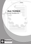
The Busch vacuum pump:
1. Oil Exhaust filter house
2. Inlet flange
3. Oil sight glass
4. Oil drain plug
5. Oil filling plug
6. Exhaust opening
7. Oil filter
8. Axial cooling fan pump side
9. Axial cooling fan motor side
10. Type plate
OIL TYPES
Take note of the type of oil used for the pump. Another type of oil may damage the pump. The following
types of oil can be used in the machines.
Machine type
SV2804TE
SV2808TE
SV3716TE / SV4216TE / SV3516TP
SV4221TP / SV4221TX / SV4221TB
Pump type
Oil quantity
Oil type
004
008
016D
0021-B
0.06 litres
0.25 litres
0.3 litres
0.4 litres
Viscosity VG 22
Viscosity VG 32
Viscosity VG 32
Viscosity VG VG 32
Examples of supplier’s brands of these types of oil are Shell Vitrea 32, Aral Motanol GM 32, BP Energol
CS 32 or Texaco Regal R+ O 32.
Machine type
SV5263SP / SV3263SP / SV5263SA
/ SV8063SA / SV4563DA /
SV5263SS / SV6263DS
SV8010SA / SV5510DA / SV8010SS
/ SV6210DS
SV6216DS
SV8430DS / SV1130DS
Pump type
Oil quantity
Oil type
063-122
1 litres
Viscosity VG 100
100-132
2 litres
Viscosity VG 100
160-132
302-132
6.5 litres
6.5 litres
Viscosity VG 100
Viscosity VG 100
Examples of supplier’s brands of these types of oil are Shell Vitrea 100, Aral Motanol GM 100, BP
Energol CS 100 or Texaco Regal R+ O 100. The quantities of oil in the table are appropriate for the
relevant pumps. The quantities of other types may differ. If the machine is used beyond normal
ambient temperature specifications, consult your supplier for the correct type of oil.
49
Busch oil lubricated vane pump
1
2
3
4
5
6
7
8
9
10
11
12
13
14
15
16
17
1 Exhaust air
2 Air inlet
3 Gas ballast valve
4 Inlet screen
5 Non return valve
6 Exhaust filter
7 Top compartment
8 Oil return bolt
9 Oil level top compartment
10 Exhaust valve
11
12
13
14
15
16
17
50
Rotor
Oil inlet
Lower compartment
Oil level lower compartment
Air inlet, from gas ballast
Vanes
Oil filter
Problem recognition
Vacuum:
Possible problems:
1.
2.
3.
4.
5.
6.
7.
The vacuum process will not start
It takes to long to reach a proper level of vacuum.
It is impossible to reach a proper end vacuum.
The bag is not tight around the product (immediately after packaging process)
During the vacuum process the vacuum bag is expanding enormously.
During the vacuum process the bag is starting to move.
The level of vacuum is not consisted
The bag is not tight around the product (after a few days of storage)
Possible causes:
1.
2.
3.
4.
5.
6.
7.
Mal functioning from the micro switch, or mal functioning from the vacuum valve.
The capacity from the pump is reduced.
The machine is leaking.
Improper setting from the vacuum level.
Distance between seal bar and counter bar is to small.
Proper functioning of the valves should be checked.
Possible damages from the vacuum bag
Possible released air that was trapped inside the core of the product
51
Possible solutions:
1. Check the proper functioning from the micro switch.
Check the proper functioning from the vacuum valve, electrical and pneumatically (membrane)
2. Check the quality and quantity of the oil / filters.
Change oil:
check the condition of the oil, (If very dirty decrease service indicator)
Change oil filter.
Check oil exhaust filter:
If this filter is polluted you have to change.
A polluted filter will result in: oil mist inside the packaging area.
A reduction of the pump capacity.
( it will take more time to reach the proper vacuum level).
We check the pollution of the exhaust filter with help of a pressure gauge.
If the gauge is indicating a pressure 0.6 Bar or higher, replace filter.
Check inlet screen of the vacuum pump:
If this filter is polluted you can clean it.
A polluted inlet screen will result in: a reduction of the pump capacity.
( it will take more time to reach the proper vacuum level).
3. Let the machine run to high vacuum, and activate the main switch so the electrical
connection is deactivated. Check for leakage.
With help of the digital hand held vacuum meter, it is possible to visualise the
leakage very clearly.
4. Check the settings, and check the end reached pressure inside the chamber, with help of the digital
hand held vacuum meter.
52
5. Check the distance between seal bar and counter bar.
If the end vacuum of the pump and the end vacuum in the chambers are sufficient, then you must check
the position of the seal bars and the contra bars.
If the contra bars and the seal bars are in line with each other you
measure the space between the seal bar and the contra bar.
This you can do with clay as follows: from clay you make 3 small
block of 15 x 15 x 15 mm and place these on both ends and in the
middle of the contra bar or seal bar depending on the model. Close
the lid to the start the vacuum process and when the vacuum meter
has reached 0,8 Bar you push the stop button.
STOP
When the lid has opened you take the clay blocks of the bars and
You measure the height. This height must be in between the 7 and 10 mm and equal over the total
length of the seal bar.
If the space between seal bar and counter bar is to little then the air that needs to get out of the bag
finds to much resistance to escape. You will have a perfect vacuum in the chamber while there is still
air in the bag.
Possible reasons why the space between the contra bar and the seal bar is to small
Dirt in the hole’s of the seal bar or contra bar so it does not stand in it’s lowest position.
Position of the seal cylinders
When the seal cylinders are adjusted to tight then the seal bar get’s stucked so it can not
come back in it’s lowest position.
Pollution of the seal valve so it does not close totally. Because of this the seal bars will move
up during the vacuum process and will close the open end of the vacuum bag.
When you have a leakage on the bottom side of the seal cylinder’s then the seal cylinders come up
during the vacuum process and this will also close the open end of the vacuum bag.
6. Check proper functioning of the vacuum valves.
Specially the membrane, the seals and the spring
7. Check the vacuum bag on possible damages, check if it is possible that the air was trapped inside the
product, and was released after some time.
53
Gas:
Possible problems:
1.
2.
3.
4.
5.
There is no gas in the package at all.
There is not enough gas in the package .
The amount of gas in the different packages is not equal
The level of gas supply not consisted, happening after a few hours of use.
The machine is gas flushing on the left side of the machine but not on the right side
(only in case of a double chamber)
Possible causes:
1.
2.
3.
4.
5.
Disconnected or broken wires to the gas valve
There is no gas supply to the machine.
Insufficient setting for gas.
The position of the bag and or the gas nozzle is improper.
There is a pollution in the connection hose a that gas nozzle.
The position of the one bag and or one gas nozzle is improper.
The gas reducing unit is freezing. This is clearly showing by ice forming on the gas regulator
The micro switch for gas is mal functioning or needs to be adjusted.
Possible solutions:
1.
2.
3.
4.
5.
Check the electrical connection to the gas valve.
Check the setting for gas, check the gas supply from the bottle.
Increase the setting, try to use a lower pressure or increase the size of the vacuum bag.
Check the position from gas nozzle.
Check the hoses.
Check the position from gas nozzle.
Use a gas regulator with a bigger capacity, or a heating element.
Check the adjustment and / or the proper functioning from the micro switch.
54
Sealing:
Possible problems:
1.
2.
3.
4.
5.
6.
7.
The seal is burning.
The bags are sticking to the seal bar.
The seal is not equal.
The seal image is perfect, but it has no strength.
The seal area is full of wrinkles.
During sealing the vacuum level drops
If the cycle is finished, there is no seal
Possible causes:
1.
2.
3.
4.
5.
6.
7.
The setting for seal time is to high.
The Teflon layer on the seal bar is damaged.
There is insufficient seal pressure.
Due to a pollution on the seal area, the warmth could not transmitted to both film sides.
The distance between seal bar and counter bar is to big, the used bag is to big in relation to the product.
The seal cylinders are not fastened properly.
The setting for gas is far to high.
Possible solutions:
1. Decrease the setting, and try again.
2. Change the Teflon layer on the seal bar.
3. If gas is used, try a new cycle without gas. (properly the seal pressure is decreased due to the use of gas
4.
5.
6.
7.
If gas was not used, check the proper functioning of seal cylinders or bags (depending on the type of
machine) A damaged membrane or seal bag will result is a insufficient seal pressure.
Clean the seal area, or try with an empty bag.
Check the distance between seal bar and silicone holder, it should be between 6 and 8 mm.
If this distance would be to big, check position of the seal bar, seal cylinders or seal bags.
Fasten the seal cylinders.
Check the setting for gas. Decrease it and test again.
55
Soft-air:
Possible problems:
1. The soft-air function is not working.
Possible causes:
1. The soft-air function is not activated.
2. Disconnected or broken wires to the soft-air valve.
Possible solutions:
1. Check the setting
2. Check the electrical connection from the valve.
Decompression:
Possible problems:
1. The decompression function is not working.
2. The machine is decompression only partial.
Possible causes:
1. Disconnected or broken wires to the decompression valve.
2. The membrane of the decompression valve is damaged.
The vacuum valve is not closed completely
Possible solutions:
1. Check the wires and the voltage to the decompression valve.
2. Check if the membrane of the decompression valve is damaged.
Check if the vacuum valve is working properly.
56
Digital control
Possible problems:
1. The Display doesn’t light up
2. The first display lights up and shows the program number, the second display is counting but nothing
works.
3. Display is showing tree little stripes which are jumping up and down.
4. Lid is open and the control is running though the program numbers.
Possible causes:
1.
2.
3.
4.
No powersypply.
Fuses burned
Lid is closed, and machine is decompressing.
Micro switch is still closed.
Possible solutions:
1. Check the main power supply
Check the main switch at the back side of the machine.
Table Models
Single / double chamber models
Check the fuse on the control transformer 250 mA 9 Volt connection.
Check the fuse on the printed circuit board 250 mA
Check the connections on the cables
Check the 15 pins connector on the PCB
All items checked but still no solution
Replace the PCB board. Try the different functions, if everything seems to work, put back
the previous PCB board. If the actual problem was caused by the PCB board, the machine
should malfunction again.
If the machine function well with the old board ( that was malfunction before), the actual
cause of the problem is probably coming from, bad connection from connector and PCB
board, or a breakage in the cable itself.
57
Maintenance:
Weekly ( done by the customer)
Check condition seal bar:
Teflon tape, seal wires, and position.
Check condition of seals:
Counter profile for sealing, lid seal
Check condition of pump:
Oil level, oil quality
Use Program “C” specific with Table models, and single chambers where sleeper function is active.
Every 4 till 6 month (done by service technician)
Check the vacuum level:
Change oil: check the condition of the oil,
If very dirty decrease service indicator
If clean increase service indicator
Change oil filter.
Check oil exhaust filter: If this filter is polluted you have to change.
A polluted filter will result in: oil mist inside the packaging area.
A reduction of the pump capacity. ( it will take more time to reach the
proper vacuum level).
We check the pollution of the exhaust filter with help of a pressure gauge.
If the gauge is indicating a pressure 0.6 Bar or higher, replace filter.
Check inlet screen of the vacuum pump:
If this filter is polluted you can clean it.
A polluted inlet screen will result in: a reduction of the pump capacity.
( it will take more time to reach the proper vacuum level).
58
Check condition seal bars:
For the correct maintenance on the seal bar check the instruction seal bar.
Teflon tape, seal wires, and position.
Check the position of the seal with help of thermic labels.
Check the gap between seal bar and counter bar:
Specially if the vacuum level from the pump and inside the
chamber is correct, but the vacuum bag is not tight around
the product
Check hinge parts:
And lubricate if possible:
use Molycote Foodslip EP 2 Grease
USDA classification H1
59
Seal bar options / materials:
Seal wires
Teflon tape
Single seal
3,5 x 0,3
0305000
0305515
Double seal
2 x (3,5 x 0,3)
0305000
0305515
Cut-off seal
3,5 x 0,3 + Ø 1,1 mm
0305000
0305010
0305515
Seal 1-2
3,5 x 0,3 + Ø 1,1 mm
0305000
0305010
0305515
Bi- active seal
8 x 0,2 mm + 5 x 0,2 mm
0305025
0305020
0305515
(Double chamber)
Biactief
2 x (5 x 0,2 mm)
0305020
0305515
8 x 0,2 mm
0305025
0305515
(Single chamber)
8 mm seal
60
SERVICE KIT FOR PUMP TESTING
PORTABLE DIGITAL VACUUM METER
Type:GMH 3160-12 / 0 - 1300 MBAR ABSOLUTE
The vacuum meter is applicable for the following services:
Check-up on the achieved and/or required final pressure in the vacuum chamber. The vacuum
meter must either be placed into the chamber or the meter must be connected to the machine
vacuum level display by the hose coupling on the top of the meter.
Check-up final pressure vacuum pumps.
The results of services with the vacuum meter can be used for:
Check the machine system for leakages.
Comparative measurements with machine display results.
Pay attention that the results must be seen as an indication as the precision
has limitations.
The meter in the service kit comes with 0,5 meter connection hose and T-shape
EXHAUST FILTER CONTROL METER
Connection plug 1”
The exhaust filter control meter is applicable for the following services:
Check-up pollution rate / condition of the exhaust filters inside the vacuum pump (it is not
necessary to take the filters out). The different connection plugs are for the different capacity
pumps in the pump range.
61
SEAL WIRE TENSION UNIT
#0930310
Seal bar placed up side down in base fork.
Cross head screw.
Locking shaft.
Tension shaft/handle.
By turning the handle the seal wire can be mount under tension and locked with the crosshead
screw.
62