1
Installation manual
1.
Operating unit BE 500
Installation
1.1. Installation notes
D Only install the equipment in dry, attended interior rooms.
Ambient conditions should be taken into account (see page 18).
D Operating control and display elements must be positioned at eye level.
D Only use the installation material recommended by UC--ST, otherwise it will
not be possible to guarantee against interference.
D Do not operate devices which have condensation on them.
D Push a ferrite sleeve on the NYM 3x1.5 power cable (230 V).
D Clip a flap ferrite onto the data cable.
D Observe the usual precautionary measures for CMOS technology when
handling printed circuit boards.
D Caution ESD (electrostatic discharge)
Ensure that the usual measures and instructions with regard to
electrostatic discharge are observed.
D Observe any electrical connection conditions currently enforced by local
authorities (fire service).
D If a BAT 100 LSN remote display panel is mounted in addition to the
BE 500 as an LED individual display detector group, it should be fitted
casing to casing with the BE 500.
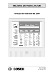
1.2. Dimensions
270
Alarm
75
Fire
Fire
Message
External Alarm Internal Alarm
BOSCH Safety Technology
Malfunction
System
Next Type
of Message
Next
Message
Next
Detector
Verification
time
Code
Reset-System
Switch off
Zone-Detector
ABC
Sounder/
Strobe
JKL
Transmission
unit
STU
Action
Transmission unit
Power supply
Operation
Code operation
Day operation
Maintenance
Control
Transmission unit
Switch off
Transmission unit
Sounder/Strobe
Internal Buzzer
01
2
0
Reset
Control
Day--Night
on/off
1
4
Maintenance Extinguishing
system
Addit.
function
Switching
point
7
2
DEF
Siren
3
GHI
5
6
MNO PQR
8
VWX YZ
CE 0
270
Sounder/Strobe
9
enter
--/:
no
page 3
stop
yes
BDL--4998100589
A1.en / 06.12.2000
ST--FIR/ PRM1/ deh