1
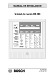
Installation manual
Operating unit BE 500
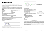
Strip the data cable and fix it to the
mountings using cable ties for strain
relief.
Clip a flap ferrite onto the data cable.
Solder on the connector and plug it in.
Connect the shielding the wire.
(see also chapter 2, Connections)
Data cable passage
Cable tie
mountings
Shielding wire
terminal
SINE
T 500
MAINS
230 V
Input
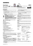
With a 230V power supply:
Screw in the mains fuse (SINE T500).
L1
N
Isolating jumper
CTS
OV3
1 2 3
14FB14
19FB19
23FB23
ON BE
6 FB6
7 FB7
1 FB1
2 FB2
4 FB4
Continued
OUT IN
(POWER)
DOWN LOAD
8 FB8
9 FB9
12FB12
-- +
10V...15V
SDO-SDO+
SDI-SDI+
Input
With a 230V power supply:
Screw in the SINE T 500 (mains fuse).
Fit the system voltage (and current
measurement) isolating jumper
(POWER).
overleaf
page 8
BDL--4998100589
A1.en / 06.12.2000
ST--FIR/ PRM1/ deh