1
Vorne Industries
Model 77/719
Analog to Digital Display
User's Manual
1445 Industrial Drive · Itasca, IL 60143-1849 · (630) 875-3600 · Telefax (630) 875-3609
Model 77/719 Analog to Digital Display
Table of Contents
1.
INTRODUCTION TO THE DISPLAY
1.1
2.
WIRING AND SPECIFICATIONS
2.1
2.2
2.3
2.4
2.5
2.6
2.7
2.8
3.
Display ...................................................................................................... 3
Input Range ............................................................................................... 3
Scaling the Display ..................................................................................... 3
Reset ......................................................................................................... 4
DC Output Voltage ................................................................................... 4
Power Requirements .................................................................................. 4
Accessing the Logic Board ........................................................................ 4
Wiring ....................................................................................................... 4
CALIBRATION PROCEDURE
3.1
3.2
3.3
3.4
3.5
3.6
3.7
3.8
3.9
Page 2
Operation .................................................................................................. 3
Equipment Needed .................................................................................... 5
Location of Trim Potentiometers ................................................................ 5
Logic Board Overview .............................................................................. 5
Calibration Procedure ................................................................................ 5
Verification ................................................................................................ 6
Selecting Normal Mode ............................................................................. 6
Securing Trim Pot Setting ........................................................................... 6
Notes ........................................................................................................ 6
Dimensions ................................................................................................ 7
Model 77/719 Analog to Digital Display
1. INTRODUCTION TO THE DISPLAY
1.1 Operation
The model 77/719 accepts analog input data, converts it to digital information, scales it in accordance with user
preset scale factor switches and displays the scaled data on 3.3 inch high digits. Various standard voltage and current
analog input ranges are available and special ranges can be accommodated. Over range analog inputs are indicated
by flashing nines on the display. Two sets of rotary dip switches are available to the user for scaling the display.
One sets the bottom while the other sets the top of the analog input range. The display is linear between the two
set points. Display accuracy is to three significant digits.
2. WIRING AND SPECIFICATIONS
2.1 Display
The display contains from 2 to 6 digits with 3.3" high LED characters. An optional decimal point in front of any
digit position is available.
2.2 Input Ranges
1) Voltage
All three voltage input ranges (0-1 Volt, 0-5 Volt, 0-10 Volt) have an input impedance such that the maximum
current drawn by the unit will be .05 milliamp at the top of the input range.
2) Current
The current input range (4-20 milliamps) has an input impedance of 44 ohms between terminals 6 and 7,
thereby creating a voltage drop of less than 1 Volt at the top of the input range.
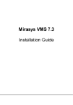
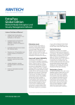
2.3 Scaling the Display
Two sets of four rotary BCD dip switches on the main logic board allow the user to select bottom-of-range
("Floor") and top-of-range ("Ceiling") values. The three rightmost switches in each set (labeled MSD, D2 and LSD)
set specific numbers. The leftmost switch in each set (labeled # of zeros) determines the number of following zeros
(up to 3). The bottom of range corresponds to the lowest valid analog input value, and the top of the range
corresponds to the highest valid analog input value. A new setting of the scaling switches is entered after reset or
power up.
Example: Bottom of range set to 1-1-5-0, top of range set to 1-8-5-0. Bottom of range = 150 x 101 = 1500;
Top of range = 850 x 101 = 8500.
BOTTOM OF RANGE
No. of Zeros
6
5
4
7 8
3 2
9
0
1
MSD
6
5
4
7 8
3 2
TOP OF RANGE
D2
9
0
1
6
5
4
7 8
3 2
LSD
9
0
1
Model 77/719 Analog to Digital Display
6
5
4
7 8
3 2
No. of Zeros
9
0
1
6
5
4
7 8
3 2
9
0
1
MSD
6
5
4
7 8
3 2
D2
9
0
1
6
5
4
7 8
3 2
LSD
9
0
1
6
5
4
7 8
3 2
9
0
1
Page 3
2.4 Reset
Internally pulled high, this active low input requires a contact closure to ground with a minimum 10 millisecond
duration. A reset input places the unit in a state equivalent to power up (ready to accept an input, display showing scaled
analog input).
2.5 DC Output Voltage
A regulated output voltage of 5 or 12 volts DC at 100 milliamps can be provided for auxiliary use.
2.6 Power Requirements
120 VAC ± 15% *, 15 VA. AC hot and neutral are wired to terminal #1 and #2 (polarity not important).
Terminal #3 is Earth Ground only.
* Also available in 220 VAC & 24 VDC.
2.7 Accessing the Logic Board
All wiring points are located on the logic board of the 77/719. This board is mounted to the front panel of
the display. For access, remove the six #8 screws which hold the front panel to the rest of the enclosure.
Warning - Shock Hazard
Disconnect power to the display prior to removing the front panel.
Do not reapply power until the front panel has been reinstalled.
2.8 Wiring
1
120
VAC
2
120
VAC
3
EARTH
GND
4
DC
GND
5
+DC
OUT
6
IN
+
7
IN
-
8
RESET
Screw terminal strip, mounted on a PC board inside the enclosure
SAFETY GROUND : On AC power units, use a 3 wire
grounded power cord with the earth ground tied to terminal 3.
3 CALIBRATION PROCEDURE
NOTE: Units are calibrated at the factory and re-calibration should not be necessary. The re-calibration
procedure should be performed if any one of the following symptoms are observed:
1) With the minimum specified input, the unit displays backward "C"s ( ]]] ).
2) With the minimum specified input, the unit displays any number not equal to the bottom range in scale
mode or > 0 in percent mode.
3) With a maximum specified input, the unit displays any out of range number.
Please consult with the factory concerning questions about the calibration procedure or re-calibration.
Page 4
Model 77/719 Analog to Digital Display
3.1 Equipment Needed
One or two digital voltmeters, capable of measuring milli volts and milliamps. The calibration instructions
are written for two DVMs between test points. See Section 3.3 for a diagram of the 77/719 logic board showing
calibration points.
3.2 Location of Trim Potentiometers
There are three 20 turn pots which are adjusted in the calibration procedure. The first is the Op Amp gain
adjust, a 10K Ohm pot (marked on its side "103") located next to the eight pin LM308 Op Amp IC. There should
also be a short piece of wire extending vertically from the logic board next to the Op Amp. This is the test point
for reading the output voltage of the Op Amp. If this wire is missing reading must be taken directly from pin 6 of
the LM308. The second pot is the A/D zero adjust, a 50K Ohm pot (marked on its side "503") located next to the
16 pin AD2020 A/D converter IC. The third pot is the A/D gain adjust, a 10K Ohm pot (marked on its side "103")
also located next to the AD2020.
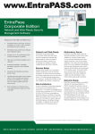
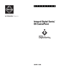
3.3 Logic Board Overview
Terminal Strip
Transformer
8
LM
308
Op-Amp
Gain
1
Test Point - 1
Test Point - 2
AD
Gain
16
AD
2020
*
AD
Zero
1
40
A
B
J1A - Current
J1B - Voltage
A
B
J2A - Scaled
J2B - Percent
Scaled Display Range
Processor
1
* CA3162 is an equivalent part.
3.4 Calibration Procedure
Note: Units that have 4-20 mA or 1-5 V input are calibrated as if they are 0-20 mA, or 0-5 V
respectively. This is because the microprocessor software compensates in normal scaled mode operation
for this special scaling requirement.
1) Selecting Calibration Mode
Power down the display and activate the calibration mode by moving the shorting jumper near pin #21
of the microprocessor from the scaled position to the percent position. Power up the display.
Model 77/719 Analog to Digital Display
Page 5
2) Op Amp Gain Adjust
Use DVM #1 to read the input at terminals #6 and #7. Use DVM #2 to read the voltage (in milli volts) out
of the Op Amp utilizing the test point. Adjust the input so it is at maximum at terminals #6 and #7 (DVM #1). For
a 4-20 mA input, maximum is 20.00 mA. For a voltage input maximum is generally 1.000 V, 5.000 V or 10.00 V
depending on the type of input ordered.
With the input at maximum, trim the Op Amp gain pot so that the op amp output (DVM #2) is 1.000 Volts exactly.
3) A/D Zero Adjust
Adjust the input at terminals #6 and #7 so it is at 0.000 (whether the input is current or voltage). Trim the
A/D zero adjust pot so that the display reads 000. A lower case backwards “c” in the third position of the display
indicates under range.
4) A/D Gain Adjust
Adjust the input so it is at maximum (as in step 2). Trim the A/D gain pot until the display is on the threshold
between 999 and lower case backward "c"s (]]]).
3.5 Verification
To verify proper calibration use the chart below. Locate the row which is marked to correspond with the
input type you have. Use the listed values as inputs on terminals 6 & 7. The displayed value should correspond
with the bottom row of the chart for each input level. If there is any disparity repeat steps 2-5.
% FULL RANGE
0%
25%
50%
75%
100%
INPUT TYPE:
INPUT TYPE:
INPUT TYPE:
INPUT TYPE:
INPUT TYPE:
0.00 mA
0.0 mV
0.000 V
0.000 V
0.000 V
5.00 mA
250.0 mV
1.250 V
1.250 V
2.500 V
10.00 mA
500.0 mV
2.500 V
2.500 V
5.000 V
15.00 mA
750.0 mV
3.750 V
3.750 V
7.500 V
20.00 mA
1000.0 mV
5.000 V
5.000 V
10.000 V
000
249-251
499-501
749-751
999-]]]
4-20 mA
0-1 V
0-5 V
1-5 V
0-10 V
Display should show
3.6 Selecting Normal (scaled) Mode
Power down the display and return the shorting jumper near pin #21 of the microprocessor to the scaled
position. The display will now operate per Section 1.1 (Operation).
3.7 Securing Trim Pot Setting
After the unit is calibrated, secure the trim pot settings by dotting silicon rubber, or nail polish on the shaft
of the pots.
3.8 Notes
_______________________________________________________________________________________
_______________________________________________________________________________________
_________________________________________________________________________________________________
_______________________________________________________________________________________________
Page 6
Model 77/719 Analog to Digital Display
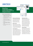
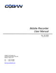
3.9 Dimension
(Not to scale)
Stand Alone Enclosure
E
H
D
B
C
K
K
3/16" Dia.
6 Places
J
E
G
F
G
F
3.0
A
A
B
3 digit
10.85
4 digit
13.60
5 digit
6 digit
3.9
C
D
E
F
G
H
J
K
7.10
9.15
3.80
.35
.55
4.87
1.05
2.25
.85
7.10
11.90
3.80
.35
.55
6.25
1.05
2.25
.85
16.35
7.10
14.65
3.80
.35
.55
7.63
1.05
2.25
.85
19.10
7.10
18.40
3.80
.35
.55
9.00
1.05
2.25
.35
All dimensions in inches.
Bezel Mount
E
H
K
L
K
C
B
D
M
3/16" Dia.
6 Places
J
E
G
F
G
F
A
- - - Dotted line indicates approximate panel cutout.
A
B
C
D
E
F
G
H
J
K
L*
M*
3 digit
11.75
4 digit
14.50
7.0
9.15
3.80
.30
1.0
4.87
.45
.65
.45
10.85
5.90
7.0
11.90
3.80
.30
1.0
6.25
.45
.65
.45
13.60
5 digit
5.90
17.25
7.0
14.65
3.80
.30
1.0
7.63
.45
.65
.45
16.35
5.90
6 digit
20.0
7.0
18.40
3.80
.30
1.0
9.00
.45
.65
.45
19.10
5.90
All dimensions in inches.
* Dimensions of panel cutout.
Model 77/719 Analog to Digital Display
Page 7
Vorne Industries Incorporated
1445 Industrial Drive
Itasca, IL 60143-1849
Phone: (630) 875-3600
Fax: (630) 875-3609
P0061R05