1
Vorne Industries
87/712
Parallel Input Module
User's Manual
1445 Industrial Drive
• Itasca, IL 60143-1849
• (630) 875-3600
• Telefax (630) 875-3609
Chapter 1 Introduction . . . . . . . . . . . . . . . . . . . . . . . . . . . . . . . . . . . . . . . . . . . . . . . . . . . .
. 2
1.1 Accessing Wiring Connections And Selection Switches . . . . . . . . . . . . . . . . . . . . . . 2
1.2 Setting The DIP Switches For Your Application . . . . . . . . . . . . . . . . . . . . . . . . . . . . . . 2
Run and Program Modes . . . . . . . . . . . . . . . . . . . . . . . . . . . . . . . . . . . . . . . . . . . . . . . . . . . . . . . . . . . . . . 2
DIP Switch Settings . . . . . . . . . . . . . . . . . . . . . . . . . . . . . . . . . . . . . . . . . . . . . . . . . . . . . . . . . . . . . . . . . . . . 3
Input Mode . . . . . . . . . . . . . . . . . . . . . . . . . . . . . . . . . . . . . . . . . . . . . . . . . . . . . . . . . . . . . . . . . . . . . . . . . . . . 3
Strobe Active Level . . . . . . . . . . . . . . . . . . . . . . . . . . . . . . . . . . . . . . . . . . . . . . . . . . . . . . . . . . . . . . . . . . 4
Strobe Mode . . . . . . . . . . . . . . . . . . . . . . . . . . . . . . . . . . . . . . . . . . . . . . . . . . . . . . . . . . . . . . . . . . . . . . . . . . 4
Debounce Time . . . . . . . . . . . . . . . . . . . . . . . . . . . . . . . . . . . . . . . . . . . . . . . . . . . . . . . . . . . . . . . . . . . . . . 5
Number Format . . . . . . . . . . . . . . . . . . . . . . . . . . . . . . . . . . . . . . . . . . . . . . . . . . . . . . . . . . . . . . . . . . 5
1.3 Parallel Input Connectors . . . . . . . . . . . . . . . . . . . . . . . . . . . . . . . . . . . . . . . . . . . . . . . . . . . 6
1.4Wiring to the Parallel Port . . . . . . . . . . . . . . . . . . . . . . . . . . . . . . . . . . . . . . . . . . . . . . . . . . . . . 6
Relay Connectors . . . . . . . . . . . . . . . . . . . . . . . . . . . . . . . . . . . . . . . . . . . . . . . . . . . . . . . . . . . . . . . . . . . . . . 9
Activate Relay . . . . . . . . . . . . . . . . . . . . . . . . . . . . . . . . . . . . . . . . . . . . . . . . . . . . . . . . . . . . . . . . . . . . . . . . . 9
Appendix A Character Representation . . . . . . . . . . . . . . . . . . . . . . . . . . . . . . . . . . . . .
11
Notice Of Disclaimer
While the information in this manual has been carefully reviewed for accuracy, Vorne
Industries, Inc. assumes no liability for any errors, or omissions in the information. Vorne
Industries also reserves the right to make changes without further notice to any products
described in this manual.
87/712 Parallel Input Module Users Manual
1
Chapter 1 Introduction
The 87/712 Parallel Module is a plug-in module for an 87/232 Series Display. The Parallel
Module incorporates 16 Data Inputs, a Strobe input and a Return line. The unit accepts parallel or
multiplexed BCD inputs and converts it to a digital display. The unit can be customized to your
particular application using VDP4. VDP4 is a Windows based utility that allows customization
of the 87 Series Display. VDP4 is available from Vorne at no charge.
1.1
Accessing Wiring Connections And Selection Switches
All external power and communication line connections to the display are made to printed circuit
board mounted terminal strips. These terminal strips, as well as a 10 position DIP switch, and
COM PORT selection switch, can be accessed by removing the back panel user access plate.
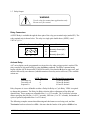
WARNING - SHOCK HAZARD
Always completely disconnect power from the display before
opening the user access plate. Do not reapply power to the
display until the access plate has been reinstalled and
securely closed.
There are two 7/8" conduit openings on the back panel of the display, provided for bringing
external wiring into the display enclosure. If these conduit openings will not be used for wiring,
these openings can be filled with plastic plugs (Caplugs Part Number BP-7/8) which are provided
with the display.
The left most conduit opening is provided for power wiring, the right most for signal wiring. It is
not recommended to run power wiring and signal wiring in the same conduit!
1.2
Setting The DIP Switches For Your Application
Note: Changes to the DIP switches are only acknowledged at power up. Factory default settings
are shown in gray.
Note: Installing the 87/712 module overrides the DIP switch settings of the 87/232 Logic board.
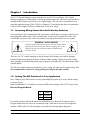
Run and Program Modes
1
Mode
ON
Program
OFF
Run
For normal operation the Run/Program switch should be set to Run (off). Setting the unit to
Program mode allows the unit to be customized using VDP4 and to run one of two diagnostic
routines. If DIP switch 2 is off, the display cycles thru the following display diagnostic.
2
87/712 Parallel Input Module Users Manual
a. Error status
Should show E0. E1 or E2 indicates a memory error.
b. Unit Address
Default value is 00.
c. Red segment test The unit will turn on 1 segment at a time A thru G and DP.
d. Green segment test. For a single color display a blank screen will be displayed.
e. All segments ON.
f. Unit type.
2 = 87/712
g. --.
This is a separator between the Unit type and the Software version.
h. Software version. This number is displayed on two consecutive screens (Ex: 1.2.6).
If DIP switch 2 is on, the display runs a DIP switch diagnostic. This diagnostic displays the HEX
value of DIP switches 3 thru 10 (switches 3 to 6 = MSD, switches 7 to 10 = LSD). If switches 3
thru 10 are all set to the ON position, the display turns on all LEDs.
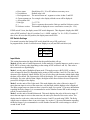
DIP Switch Settings
For normal operation the Settings DIP switch should be set to DIP switch (on).
In program mode, Switch 2 selects between Display test (off) and DIP switch test (on).
2
Settings
ON
DIP Switch
OFF
VDP4
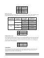
Input Mode
This setting determines the Input Mode that the parallel module will use.
Mode 0 sets the unit to Parallel Input mode. In this mode the 16 parallel inputs are used to enter a
BCD, HEX, or binary value (depending on the setting of DIP switches 9 and 10). This value is
then converted to a digital display.
Mode 1 sets the unit to Multiplexed Input mode. This mode accepts a BCD, HEX, or binary
value at Inputs D0 thru D3 (depending on the setting of DIP switches 9 and 10). This value is the
character to be displayed. Inputs D8 thru D15 act as select lines and determine which display digit
the data will be shown. D8 represents the LSD of the display. D15 represents the 8th character of
the display. For units with less than 8 digits, the higher strobe lines need not be used. Repeat this
process for all digits of the display.
Mode 2 sets the unit to Pilot Light mode. This mode displays the value of the active input. If
more than one input is active at the same time, only the Input with the highest value is displayed.
The Relay output turns on whenever there is an active input. See section 1.5 for more information
regarding the Relay Output. It is recommended to set the Number Format DIP switch settings to
switch 9 on and switch 10 off.
Mode 3 sets the unit to Round Robin mode. This mode displays the value of the active input. If
more than one input is active at the same time, the unit cycles thru all of the active values. The
display time for each active value can be set between 1 and 25 seconds using VDP4. The Relay
output turns on whenever there is an active input. See section 1.5 for more information regarding
the Relay Output. It is recommended to set the Number Format DIP switch settings to switch 9
on and switch 10 off.
87/712 Parallel Input Module Users Manual
3
3
4
Input Mode
OFF OFF Parallel Data
OFF
ON Multiplexed
ON
OFF Pilot Light
ON
ON Round Robin
Data Active Level
This setting determines the Data Active Level the parallel module will use. This setting affects the
parallel inputs D0 to D15. Use the table below to select the correct Data Active Level.
87/712 Return
Connection
Input Logic Type
Selected
Low
+V
High
High
GND
Low
PLC Output
Voltage
Open or +V
GND
Open or +V
GND
Open or GND
+V
Open or GND
+V
5
Data Active Level
ON
High
OFF
Low
Interpreted By
87/712 As
"0" (Inactive)
"1" (Active)
"1" (Active)
"0" (Inactive)
"0" (Inactive)
"1" (Active)
"1" (Active)
"0" (Inactive)
Strobe Active Level
This setting determines the Strobe Active Level the parallel module will use. For units which have
Strobe mode turned Off, (Switch 7 Off) this switch setting will be ignored. This setting does not
affect the operation of the digit select inputs (D8 thru D15) when the unit is set to Multiplexed
mode (Switch 3 Off Switch 4 On).
6
Strobe Active Level
ON
High
OFF
Low
Strobe Mode
This setting turns On or Off the operation of the Strobe Input (Terminal 3 of P4). This setting
does not affect the operation of the digit select inputs (D8 thru D15) when the unit is set to
Multiplexed mode (Switch 3 Off Switch 4 On).
4
87/712 Parallel Input Module Users Manual
7
Strobe Mode
ON
On
OFF
Off
Debounce Time
The Debounce time for Inputs D0 thru D15 and the Strobe input is field programmable to low or
high speed by setting this DIP switch. When using a input device such as a switch or a relay
contact, set the input rate to low speed. This will prevent false counts caused by contact bounce.
For input devices such as PLC NPN (Sinking) or PNP (Sourcing) outputs, set the input rate to
high speed. Shielded wire for the input is recommended when the unit is set to high speed but not
required for low speed.
8
Debounce Time
ON
High
OFF
Low
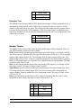
Number Format
The Number Format selection determines how the parallel inputs will be interpreted. There are
four different number format selections available.
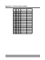
BCD specifies that the parallel inputs will be interpreted as BCD inputs. Up to 4 digits of BCD
data can be entered. In parallel mode, the right most digit consists of D0 to D3. The second digit
from the right consists of D4 to D7. The third digit from the right consists of D8 to D11. The
MSD consists of D12 to D15. A negative sign can be displayed at any digit position by placing a
HEX A at the parallel inputs. See Appendix A for additional character representation. The range
of values is from -999 to 9,999.
HEX specifies that the parallel inputs will be interpreted as HEX inputs. Up to 4 digits of HEX
data can be entered. The range of values is from 0 to FFFF.
Signed Binary specifies that the parallel inputs will be interpreted as signed binary data. D0 to
D14 will be interpreted as binary inputs. If D15 is active the binary value is interpreted as a
negative number. Negative numbers are two's complement format. The range of values is from
-32,768 to 32,767.
Binary specifies that the parallel inputs will be interpreted as binary data. D0 to D15 will be
interpreted as binary inputs. The range of values is from 0 to 65,535.
9
10
Number Formats
OFF OFF
BCD
OFF
ON
HEX
ON
OFF
Signed Binary
ON
ON
Binary
87/712 Parallel Input Module Users Manual
5
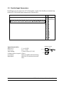
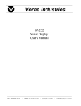
1.3 Parallel Input Connectors
Parallel Inputs can be wired to the 87/712 through the 19 pins of the Parallel port terminal strip
(marked P4). The Parallel Input terminal strip is shown below.
Pin Function
19 Pin Parallel INPUT Terminal Strip (P4)
Pins 1 to 19
1
2
3
Parallel Input Terminal Strip
4
5
6
Input characteristics
High Level
Low Level
Input loading
Leakage current accepted
Low Speed
High Speed
6
7
8
9
10 11 12 13 14 15 16 17 18 19
1
2
3
4
5
6
7
8
9
10
11
12
13
14
15
16
17
18
19
GND (Ground)
RET (Return)
STRB (Strobe)
D0
D1
D2
D3
D4
D5
D6
D7
D8
D9
D10
D11
D12
D13
D14
D15
Parallel Input Circuitry
3.5 to 30 VDC
0 to 1.5 VDC
1.5mA to 10mA (5V-30V)
450 uA
50 Hz (10 millisecond on/off time)
4000 Hz (120 microsecond on/off
time)
87/712
pin 3 to 19
Parallel
Input
6.8K
3.3K
pin 2
Return
Parallel Input Module Users Manual
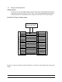
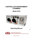
1.4
Wiring to the Parallel Port
Sinking Outputs
To operate the unit with sinking outputs, the DC Return line of the parallel port should be
connected to a positive voltage (3.5 to 30 VDC). This will internally pull up all the inputs
of the parallel port to this potential with a maximum current draw of 2.5 mA per input.
Parallel Port Wiring - Sinking Outputs
3.5 TO 30 VOLT DC USER
OUTPUT CARD SUPPLY
+
-
DC GROUND
DC RETURN
STROBE
D0
D1
D2
D3
D4
D5
D6
D7
D8
D9
D10
D11
D12
D13
D14
D15
87/712 PARALLEL PORT
1 2 3 4 5 6 7 8 9 10 11 12 13 14 15 16 17 18 19
PROGRAMMABLE CONTROLLER
DC GROUND
+ SUPPLY
OUTPUT 16
OUTPUT 0
OUTPUT 1
OUTPUT 2
OUTPUT 3
OUTPUT 4
OUTPUT 5
OUTPUT 6
OUTPUT 7
OUTPUT 8
OUTPUT 9
OUTPUT 10
OUTPUT 11
OUTPUT 12
OUTPUT 13
OUTPUT 14
OUTPUT 15
In all cases, make sure that DC ground (Terminal 1) is wired to the DC ground of the output card
supply.
87/712 Parallel Input Module Users Manual
7
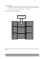
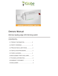
Sourcing Outputs
To operate the unit with sourcing outputs, the DC Return line on the parallel port should
be connected to DC ground. This will internally pull down all the inputs of the parallel port
to DC ground with a maximum current draw of 2.5 mA per input.
Parallel Port Wiring - Sourcing Outputs
3.5 TO 30 VOLT DC USER
OUTPUT CARD SUPPLY
+
-
DC GROUND
DC RETURN
STROBE
D0
D1
D2
D3
D4
D5
D6
D7
D8
D9
D10
D11
D12
D13
D14
D15
87/712 PARALLEL PORT
1 2 3 4 5 6 7 8 9 10 11 12 13 14 15 16 17 18 19
PROGRAMMABLE CONTROLLER
DC GROUND
+ SUPPLY
OUTPUT 16
OUTPUT 0
OUTPUT 1
OUTPUT 2
OUTPUT 3
OUTPUT 4
OUTPUT 5
OUTPUT 6
OUTPUT 7
OUTPUT 8
OUTPUT 9
OUTPUT 10
OUTPUT 11
OUTPUT 12
OUTPUT 13
OUTPUT 14
OUTPUT 15
In all cases, make sure that DC ground (Terminal 1) is wired to the DC ground of the output card
supply.
8
87/712 Parallel Input Module Users Manual
1.5 Relay Output
WARNING
Use the relay for annunciator applications only.
Do not use it for control.
Relay Connectors
A SPDT Relay is available through the three pins of the relay port terminal strip (marked P5). The
relay terminal strip is shown below. The relay is a single pole double throw (SPDT), rated
120VAC @ 1A.
3 Pin Relay Terminal Strip (P5)
A
B
C
Pin
Function
A
Normally Closed (NC)
B
Common
C
Normally Open (NO)
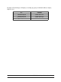
Activate Relay
A 87 series display can be programmed to activate the relay when a trigger point is reached. The
relay can also be activated serially by using the Relay command. The Relay command string
begins with the ASCII character R (52 hex/82 decimal). Note that the R must be upper case, and
must be followed by one character (which determines what relay action will occur). The available
actions are:
Action
Turn relay on
Turn relay off
Sequence A
ASCII Character
1
0
A
Hex/Decimal Representation
31 hex/49 decimal
30 hex/48 decimal
41 hex/65 decimal
Relay Sequence A is user definable as either a Delay On Relay or Cycle Relay. VDP4 is required
to change this parameter. The Delay On Relay selection allows adjustment of the delay and
duration time. These settings are adjustable from .1 to 25.5 seconds. The Cycle Relay selection
allows specifying the ON time (.1 to 25.5 seconds), OFF time (.1 to 25.5 seconds), and number of
cycles to perform (adjustable from 1 to 255 times).
The following examples assume that addressing and checksums are not being used, and that
Terminator has been selected as <CR>. Also note that the header of the packet <SOH>s: has
87/712 Parallel Input Module Users Manual
9
the effect of broadcasting to all displays, overriding any group or individual address a display
might be set to.
10
To....
Transmit
Turn the relay on
<SOH>s:R1<CR>
Turn the relay off
<SOH>s:R0<CR>
Trigger Sequence A
<SOH>s:RA<CR>
87/712 Parallel Input Module Users Manual
Appendix A Character Representation
D3 D2 D1 D0
BCD Mode
HEX Mode
representation representation
0
0
0
0
0
0
0
0
0
1
1
1
0
0
1
0
2
2
0
0
1
1
3
3
0
1
0
0
4
4
0
1
0
1
5
5
0
1
1
0
6
6
0
1
1
1
7
7
1
0
0
0
8
8
1
0
0
1
9
9
1
0
1
0
-
A
1
0
1
1
E
B
1
1
0
0
H
C
1
1
0
1
L
D
1
1
1
0
P
E
1
1
1
1
{blank}
F
87/712 Parallel Input Module Users Manual
11