1
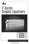
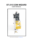
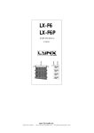
Vorne Industries
Model 77/712
BCD To Digital 3" Display
User's Manual
1445 Industrial Drive
• Itasca, IL 60143-1849
• (630) 875-3600
• Telefax (630) 875-3609
Model 77/712 BCD To Digital 3" Display
Page 2
MODEL 77/712 BCD TO DIGITAL 3" DISPLAY
Table Of Contents
1.
INTRODUCTION TO THE 77/712 DISPLAY
1.1
Operation ............................................................................................. 4
1.2
Display ................................................................................................. 4
2.
SETTING UP THE DISPLAY FOR YOUR APPLICATION
2.1
Selecting Sink Or Source Inputs ........................................................... 4
2.2
Input Types .......................................................................................... 4
3.
USING THE DISPLAY
3.1
Data Entry ............................................................................................ 5
3.2
Data Examples ...................................................................................... 6
4.
WIRING AND SPECIFICATIONS
4.1
Reset .................................................................................................... 7
4.2
DC Output Voltage .............................................................................. 7
4.3
Power Requirements ............................................................................. 7
4.4
Timing Diagram .................................................................................... 7
4.5
Wiring .................................................................................................. 8
4.6
Terminal Strip Identification ................................................................. 9
4.7
Dimensions ........................................................................................... 9
4.7
Dimensions Bezel Mount .................................................................... 10
4.8
Accessing the Logic Board ................................................................. 10
5.
APPENDICES
Appendix A
Character Set ...................................................................................... 11
Model 77/712 BCD To Digital 3" Display
Page 3
1. INTRODUCTION TO THE 77/712 DISPLAY
1.1 Operation
The model 77/712 accepts parallel or multiplexed BCD information, with either positive or negative true
logic, and converts it to a digital display. Hex values (A through F) can also be displayed.
1.2 Display
From 2 to 6 digits with 3.3" high characters.
2. SETTING UP THE DISPLAY FOR YOUR APPLICATION
2.1 Selecting Sink Or Source Inputs
The BCD and strobe inputs can be selected as active low (inputs normally pulled to +V, activated when input
is switched to DC ground) or active high (inputs normally pulled to ground, activated when input is switched to
+V).
To select active low inputs, connect the +V of your supply to the return line (terminal pin 32), and tie the
-V(ground) of your supply to DC ground (terminal pin 6). To select active high inputs, connect the -V (ground)
of your supply to the return line (terminal pin 32), and to the DC ground (terminal pin 6). See Section 4.5 Wiring.
2.2 Input Types
Two standard input types are available.
L - Low Voltage
Logic 0
Logic 1
Input Impedance
Maximum Leakage Current
0 - 1.5VDC
3.5 - 9VDC
680 Ohm
2 mA
H - High Voltage
Logic 0
Logic 1
Input Impedance
Maximum Leakage Current
0 - 6.6VDC
9 - 30VDC
3.3 K Ohm
2 mA
Model 77/712 BCD To Digital 3" Display
Page 4
3. USING THE DISPLAY
3.1 Data Entry
Up to 6 digits of BCD data can be entered. Each digit is made up of four BCD lines and one strobe line. Data
logic and strobe logic are independently user selectable as positive or negative logic via a PC board mounted
selector switch. Minimum input time duration is 20 mS. The strobe inputs can be used in four different modes.
1) Constant strobe mode: To select this mode, it is necessary to match the strobe logic with the return line
via the PC board mounted selector switch. Positive strobe logic should be selected if the return line is tied to +V,
and negative strobe logic should be selected if the return line is tied to ground. In this mode, any BCD data will
be instantaneously displayed.
2) Master strobe mode: As long as the master strobe input (terminal pin 31) is held inactive, display digits
will ignore any change of BCD input data. If the master strobe is brought to the active level, any data on the inputs
will be transfered to the respective display digits until the master strobe is brought inactive again.
3) Independent strobe mode: Each digit can have its own independent strobe. As long as the digit strobe
is held inactive, the display will ignore any change of BCD data for that digit. When the data strobe is active, the
BCD input data will be transferred directly to the display.
Note: For modes 1,2, and 3 switch #2 of the PC mounted selector switch must be in the off position (parallel
mode).
4) Multiplexed mode: In this mode BCD data is entered via pins 1 through 4 of the terminal strip. To display
data in this mode, hold all strobe lines inactive until the data to be displayed is present, then the strobe of the
selected digit should be pulsed active. This process is repeated for all of the digits on the display. To select this
mode, switch #2 of the selector switch should be in the on position.
S1 S2 S3 S4
O 1
N
S1
S2
2
S3
3
4
S4
MUX NEG NEG
ON
PAR POS POS OFF
IN
DATA STB
TYP
Model 77/712 BCD To Digital 3" Display
Page 5
3.2 Data Examples
BCD Data
0000
0001
0010
0011
0100
0101
0110
0111
1000
1001
1010
1011
1100
1101
1110
1111
Character Displayed
0
1
2
3
4
5
6
7
8
9
A
B
C
D
E
F
(positive logic)
Character Displayed
F
E
D
C
B
A
9
8
7
6
5
4
3
2
1
0
(negative logic)
* See Appendix A
Model 77/712 BCD To Digital 3" Display
Page 6
4. WIRING AND SPECIFICATIONS
4.1 Reset
Internally pulled high, active low (contact closure to ground). Requires 10 mS minimum duration signal.
Holding the reset line (terminal 5) low forces the display to an all-zero state, and places the unit in a state equivalent
to power-up. It is necessary to reset the unit in order to recognize any change in switch settings.
4.2 DC Output Voltage
Either 5.0 or 12.0 Volts DC (regulated), at 100 mA is available at terminal 7 for operating external devices.
4.3 Power Requirements
120VAC ±15% 15 VA. AC hot and neutral are wired to terminals #1 and #2 (polarity not important).
Terminal #3 is Earth ground only.
4.4 Timing Diagram
TON
STROBE
T SETUP
BCD 1-4
Model 77/712 BCD To Digital 3" Display
T HOLD
TON
T SETUP
THOLD
20mss
0mss
0mss
Page 7
4.5 Wiring
The output Voltage of the device driving the display must be compatible with the ordered input (TTL-9
VDC, 12 VDC - 30 VDC) of the display.
5-30 VOLT DC SOURCE
OUTPUT CARD
5-30 VOLT DC SINK
OUTPUT CARD
5-30 VOLT DC
USERS
SUPPLY
+
+V
GND
CONTACT
OUTPUT CARD
5-30 VOLT DC
USERS
SUPPLY
+
-
5-30 VOLT DC
USERS
SUPPLY
+
-
-
4) NC
4) NC
5) RESET
5) RESET
6) DC GND
6) DC GND
6) DC GND
7) +V OUT
7) +V OUT
7) +V OUT
32) RETURN
32) RETURN
32) RETURN
4) NC
5) RESET
+V
GND
OUT
31) MST STB
OUT
31) MST STB
31) MST STB
OUT
30) DIG 6 - STB
OUT
30) DIG 6 - STB
30) DIG 6 - STB
B
OUT
29) DIG 6 - D
OUT
29) DIG 6 - D
29) DIG 6 - D
OUT
28) DIG 6 - C
OUT
28) DIG 6 - C
28) DIG 6 - C
OUT
27) DIG 6 - B
OUT
27) DIG 6 - B
27) DIG 6 - B
OUT
26) DIG 6 - A
OUT
26) DIG 6 - A
26) DIG 6 - A
OUT
5) LSD - STB
OUT
5) LSD - STB
5) LSD - STB
OUT
4) LSD - D
OUT
4) LSD - D
4) LSD - D
OUT
3) LSD - C
OUT
3) LSD - C
3) LSD - C
OUT
2) LSD - B
OUT
2) LSD - B
2) LSD - B
OUT
1) LSD - A
OUT
1) LSD - A
1) LSD - A
OUTPUT
DEVICE
VORNE
DISPLAY
OUTPUT
DEVICE
VORNE
DISPLAY
1) Tie external supply DC ground
to Vorne DC ground.
1) Tie external supply DC ground
to Vorne DC ground.
2) Tie external supply DC ground
to Vorne Return terminal.
2) Tie external supply +V to
Vorne Return terminal.
3) Connect source outputs to
Vorne inputs.
3) Connect sink outputs to
Vorne inputs.
Model 77/712 BCD To Digital 3" Display
CONTACT
OUTPUTS
VORNE
DISPLAY
1) Tie external supply DC ground
to Vorne DC ground and to common
of switches.
2) Tie external supply +V to
Vorne Return terminal.
3) Connect contact outputs to
Vorne inputs.
Page 8
4.6 Terminal Strip Identification
1
120
VAC
2
120
VAC
3
EARTH
GND
4
NC
5
RESET
6
DC
GND
7
+V OUT
Screw Terminal Strip
TERMINAL #
1
2
3
4
5
6
7
LSD
BCD VALUE
A
B
C
8
9
10
11
12
DIGIT 2
D STB A
B
C
13
14
15
16
17
DIGIT 3
D STB
A
B
C
18
19
20
21
22
DIGIT 4
D STB A
B
C
23
24
25
26
27
DIGIT 5
D STB
A
B
C
28
29
30
DIGIT 6
D STB A
B
C
D STB
31
32
MST
RTN
STB
BCD Terminals
4.7 Dimensions
E
H
D
K
B
C
K
3/16" Dia.
6 Places
J
E
F
G
G
F
3.0
A
3.9
A
B
C
D
E
F
G
H
J
K
3 digit
10.85
7.10
9.15
3.80
.35
.55
4.87
1.05
2.25
.85
4 digit
13.60
7.10
11.90
3.80
.35
.55
6.25
1.05
2.25
.85
5 digit
16.35
7.10
14.65
3.80
.35
.55
7.63
1.05
2.25
.85
6 digit
19.10
7.10
18.40
3.80
.35
.55
9.00
1.05
2.25
.35
All dimensions in inches.
Model 77/712 BCD To Digital 3" Display
Page 9
Bezel Mount
E
H
L
K
K
C
B
M
D
3/16" Dia.
6 Places
J
E
F
G
F
G
A
--- Dotted line indicates approximate panel cutout
C
D
E
F
G
H
J
K
L*
7.0
9.15
3.80
.30
1.0
4.87
.45
.65
.45
10.85
5.90
7.0
11.90
3.80
.30
1.0
6.25
.45
.65
.45
13.60
5.90
17.25
7.0
14.65
3.80
.30
1.0
7.63
.45
.65
.45
16.35
5.90
20.0
7.0
18.40
3.80
.30
1.0
9.00
.45
.65
.45
19.10
5.90
A
B
3 digit
11.75
4 digit
14.50
5 digit
6 digit
M*
All dimensions in inches.
* Dimensions of panel cutout.
4.8 Accessing the Logic Board
All user accessable functions and wiring points are located on the main logic board of the 77/712. For access,
remove the six #8 screws which hold the front panel to the rest of the enclosure.
Warning - Shock Hazard
Disconnect power to the display prior to removing the front panel.
Do not reapply power until the front panel has been reinstalled.
Model 77/712 BCD To Digital 3" Display
Page 10
5. APPENDICES
Appendix A Character Set
0
1
2
3
4
5
6
7
8
9
A
B
C
D
E
F
Model 77/712 BCD To Digital 3" Display
Page 11
Vorne Industries Incorporated
1445 Industrial Drive
Itasca, IL 60143-1849
Tel: (630) 875-3600
Fax: (630) 875-3609
P0003R02