1
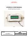
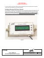
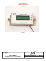
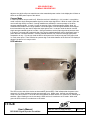
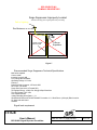
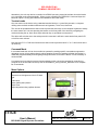
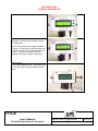
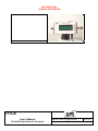
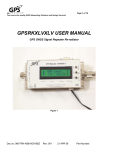
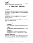
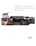
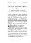
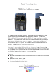
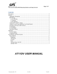
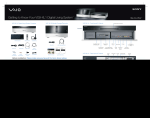
GPS SOURCE, INC.
COMPANY PROPRIETARY
060 USER’S MANUAL
PRODUCT:
RELEASED/REVISED BY:
APPROVED BY
GPS GNSS Signal
Repeater Re-radiator
Philip Coiner
Philip Coiner
PAGE: 1 of 14
REVISION HISTORY
REV. #
DATE
ECO#
DESCRIPTION
001A
01/13/09
INITIAL PRODUCTION RELEASE
003
10/30/08
UPDATE
006
2/5/08
UPDATE
008
1/12/09
UPDATE
009
3/3/09
UPDATE
010
21 May 09
UPDATE ADDED SURGE SUPRESSOR INFO
The drawing and specification herein are property of GPS Source and
shall not be reproduced or used in whole or in part as the basis of
manufacture or sale of items without written permission.
TITLE
User’s Manual
GPS GNSS Signal Repeater Re-radiator
DWG NO.
REV
060-FAV-AAB-AAX-BBZ
-010
GPS SOURCE, INC.
COMPANY PROPRIETARY
GPSRKXLV USER MANUAL
GPS GNSS Signal Repeater Re-radiator
Figure 1
TITLE
User’s Manual
GPS GNSS Signal Repeater Re-radiator
DWG NO. 060-FAV-AAB-AAX-BBZ
SHEET 2 OF 17
REV: 010
GPS SOURCE, INC.
COMPANY PROPRIETARY
Description ........................................................................................................................................ 5 Features ............................................................................................................................................. 5 Adjustable Output Power .........................................................................................................................5 RF Filtering ................................................................................................................................................5 Antenna/RF Line DC voltage ...................................................................................................................5 Antenna Current Fault Detection (Ant Fault Detect, Optional) ...........................................................5 Oscillation Detection (OSC Detect, Optional) .........................................................................................6 ERP Level Adjust ......................................................................................................................................8 Canyon Mode .............................................................................................................................................9 LED Indicator ............................................................................................................................................9 LCD display .............................................................................................................................................10 LCD Backlight .........................................................................................................................................10 Menu System ............................................................................................................................................10 Serial Port Control (Optional)................................................................................................................10 Setup ................................................................................................................................................ 10 Installation................................................................................................................................................10 Signal level requirement .........................................................................................................................12 Low signal vs. no signal ...........................................................................................................................13 High signal ................................................................................................................................................13 Fixed Output Mode .................................................................................................................................13 Operation ......................................................................................................................................... 13 Terminal mode .........................................................................................................................................14 Command Mode ......................................................................................................................................14 Menu Options...........................................................................................................................................14 Figure 1 ............................................................................................................................................. 2 Figure 2 ............................................................................................................................................. 6 Figure 3 ............................................................................................................................................. 7 Figure 4 ............................................................................................................................................. 8 Figure 5 ............................................................................................................................................. 9 Figure 6 ........................................................................................................................................... 11 Figure 7 ........................................................................................................................................... 12 TITLE
User’s Manual
GPS GNSS Signal Repeater Re-radiator
DWG NO. 060-FAV-AAB-AAX-BBZ
SHEET 3 OF 17
REV: 010
GPS SOURCE, INC.
COMPANY PROPRIETARY
DECLARATIONS
The GPSRKXLV product is intended for use as a GPS/GNSS (L Band) frequency repeater or re-radiator.
Use of this device is governed buy NTIA rules in Procedures and Principles for the Assignment and
Coordination of Frequencies. Improper use shall be considered unwarranted and could result in violation of
applicable federal rules and regulations. Changes or modifications to the equipment not expressly
approved by GPS Source, Inc. could void the user's authority to operate the equipment.
This device is intended to connect directly to an outdoor receiving antenna system. GPS Source strongly
recommends the inclusion of a coaxial surge protection in the event of lightening strikes to the outdoor
antenna. To provide protection to devices and personnel GPS Source recommends the use of devices
such as the Co-Pro - Surge / Coax Protector. Contact the GPS Source sales department for additional
information.
Operation Rules:
Per NTIA rules GPS Repeaters are to be operated by International Customers (customers outside the
U.S.), agencies of the US Federal Government, parties operating under the direction of the US Federal
Government, or parties granted an STA or Experimental License under part 5 of the FCC rules, or parties
that will be operating GPS Repeaters in a shielded room.
For further information regarding NTIA requirements in applications involving re-radiated signal, see
Section 8.3.28 of the NTIA manual found here:http://www.ntia.doc.gov/osmhome/redbook/redbook.html.
CE Marking:
The GPSRKXLV has been tested and verified to comply with applicable EU directives.
TITLE
User’s Manual
GPS GNSS Signal Repeater Re-radiator
DWG NO. 060-FAV-AAB-AAX-BBZ
SHEET 4 OF 17
REV: 010
GPS SOURCE, INC.
COMPANY PROPRIETARY
GPSRKXLV USER MANUAL
Description
The GPSRKXLV is a RF (L band) repeater/re-radiator, it transmits either L1 (1575.42MHz) only or L1 & L2
(1227.60MHz) frequencies, (L5 and other GNSS signals are possible but the internal filtering does not
currently support these signals) it requires an input signal from a GPS/GNSS source (i.e. GPS receive
antenna or GPS signal generator). It has one input RF port and one output RF port. Using front panel
buttons or an RS232 serial port, the ERP output power can be adjusted in 1dB steps over the -86dBm to 65dBm operating range of the device. The device measures the signal strength at the output and
automatically controls the output level based on the measured GPS signal level. This assures the
transmitted signal level is within the NTIA authorized range for GPS repeaters.
Features
The GPSRKXLV contains various features standard and optional. Optional features require the addition of
optional circuitry and may not be installed or applicable to your device.
Adjustable Output Power
The GPSRKXLV comes standard with adjustable output RF power from -86dBm to -65dBm.
RF Filtering
RF filtering is standard to prevent transmission of any out of band i.e. unwanted signals. There are two RF
filtering options:
L1/L2 filtering (Optional)
With L1/L2 filtering the maximum gain provided will be in the frequency bands of L1, 1575.42 MHz
and L2, 1227.60 MHz.
L1 filtering (Optional)
With L1 filtering the maximum gain provided will only be in the band only i.e.1575.42 MHz.
Note see data sheet for filter response[s].
Antenna/RF Line DC voltage
As a standard feature, the GPSRKXLV is capable of providing a switched DC voltage out each RF port to
power other devices in the RF signal chain. The unit can be externally powered by 110VAC, 220VAC,
240VAC or from a DC source (minimum 8VDC).
Antenna Current Fault Detection (Ant Fault Detect, Optional)
If the antenna current exceeds either a high or low threshold value then the device will remove power from
the antenna or input port and it will display an error message on the display and via serial port.
After approximately 10 to 13 seconds the unit will retry to see if the current fault condition has been
removed by clearing the error message and momentarily reconnecting power to the input port. If a high or
low threshold current level is no longer exceeded then the device will once again operate normally. The
exact trigger level[s] can be set via the serial port. (GPSRKXLV_Serial_Interface_Reference)
TITLE
User’s Manual
GPS GNSS Signal Repeater Re-radiator
DWG NO. 060-FAV-AAB-AAX-BBZ
SHEET 5 OF 17
REV: 010
GPS SOURCE, INC.
COMPANY PROPRIETARY
If you do not have the serial port option the factory defaults are low current threshold level is less than
15ma and the high threshold level is greater than150ma.
Oscillation Detection (OSC Detect, Optional)
The GPSRKXLV is capable of detecting high levels of RF energy which is indicative of feed back from the
output of the device to the input. If the OSC detect circuitry threshold is exceeded, the unit will remove
power from the antenna or input and it will display an error message (OSCF) on the display LCD display
and send an error message via serial port. Unlike the antenna current fault the unit will not retry and
requires a key press or equivalent character from the serial port to clear the error and to retry. The exact
trigger level[s] can be set via the serial port. (GPSRKXLV_Serial_Interface_Reference).
Figure 2
TITLE
User’s Manual
GPS GNSS Signal Repeater Re-radiator
DWG NO. 060-FAV-AAB-AAX-BBZ
SHEET 6 OF 17
REV: 010
GPS SOURCE, INC.
COMPANY PROPRIETARY
Figure 3
TITLE
User’s Manual
GPS GNSS Signal Repeater Re-radiator
DWG NO. 060-FAV-AAB-AAX-BBZ
SHEET 7 OF 17
REV: 010
GPS SOURCE, INC.
COMPANY PROPRIETARY
Figure 4
ERP Level Adjust
This device’s output is intended to be connected to a repeat or re-radiating antenna. Without the ERP level
adjust enabled the ERP level numbers in the display only reflect the power at the output connector and do
not take the retransmit antenna gain or loss into account. ERP level adjust lets the user add the antenna
gain (or loss) into the power control calculation so the numbers reflect the total system ERP level not just
the power at the output connector of the device. Most antennas have some positive gain but could just as
easily be negative, imagine a repeat antenna with positive gain connected to a long cable with enough loss
to give a negative gain overall, also many passive antennas have little or no gain by design. There are two
steps to using this function. First the user is required to set the amount of gain (positive or negative) by
navigating to the ERP level Adjust menu see Figure 2. Use the up and down arrow keys to enter a value
in the range of +3 to -3 dB see Figure 3. Then navigate to the ERP level adjust ON/OFF menu see Figure
4 and turn the option on or off. When ERP level adjust is enabled an asterisk will appear after the
transmitted power number in the display. Remember that one has the option of setting the ERP level
TITLE
User’s Manual
GPS GNSS Signal Repeater Re-radiator
DWG NO. 060-FAV-AAB-AAX-BBZ
SHEET 8 OF 17
REV: 010
GPS SOURCE, INC.
COMPANY PROPRIETARY
adjust to zero which will put an asterisk next to the transmitted power number in the display but will have no
effect on the ERP power output of the device!
Canyon Mode
In normal operation canyon mode is off. When the receiver is initializing i.e. it is in mode 1 or acquisition
mode it uses the single strongest satellite signal to set the output signal level. Whilst in mode 2 (often the
receiver will skip directly to mode 3 if enough satellites are available) it uses an average of the three
strongest satellite signals. In mode 3 it uses an average of the 4 strongest satellite signals. Note: All
measurements whether from a single satellite or three strongest or four strongest satellites are averaged
three times before they are used to adjust the output power level. In canyon mode the device uses the
single strongest satellite signal as in mode 1 during all modes to set the output signal level because when
in a canyon or an area with a restricted view of the sky the masked satellites may be significantly lower in
power than the unmasked satellites. Including masked satellites may cause the average signal power
computation to vary. If in canyon mode the device will report on the serial port as part of the power level
i.e. main menu report. There will also be a percent sign in the third character of the first line LCD display to
denote if the device is in canyon mode.
LED Indicator
Figure 5
The LED is on the side of the device as shown above (shown RED). Red indicates that the power to the
antenna is off. Green indicates that the antenna power is on. Whilst green, the flash rate indicates the
mode of the GPS receiver. A one half hertz rate indicates the GPS receiver is in mode one or searching for
satellites. When flashing at a one hertz rate the GPS receiver is in mode two or 2D mode. When solid
green the GPS receiver is in mode three or 3D mode.
TITLE
User’s Manual
GPS GNSS Signal Repeater Re-radiator
DWG NO. 060-FAV-AAB-AAX-BBZ
SHEET 9 OF 17
REV: 010
GPS SOURCE, INC.
COMPANY PROPRIETARY
LCD display
As a standard feature, the GPSRKXLV is equipped with a LCD display to provide feedback to the user.
LCD Backlight
The LCD display is equipped with an LCD back light. The back light is not available with the non-powered
option, which removes the AC power supply from the product.
Menu System
The LCD of the device has two lines of sixteen characters. The first line or top line always contains the title
of menu item selected so that you know where you are at in the menu tree. From the top level of the menu
each press of the up or down button navigates the menu system. The menu system is flat, i.e. it is a loop
of items that can be selected for modification or selected to display the current values or settings.
Once an item is selected the up and down keys can be used to change the displayed values of the
particular item. After approximately 10 seconds with no user input (button presses from the user or
characters on the serial port) the menu returns to the main screen which displays the current selected ERP
level.
Main Screen
The main screen is shown in Figure 1. The title which reads ERP Level is on the first or top line. On the
right hand side of the title is a number (3 in the picture) which shows the mode of the GPS receiver. Mode
1 denotes the GPS receiver is not yet tracking satellites. Mode 2 denotes the receiver is tracking satellites
but only has sufficient satellites for a 2D fix. Mode 3 denotes the GPS receiver has enough satellites to
compute a 3D fix and represents the highest level of accuracy. Because the power output of the device is
based on what the GPS receiver is reporting the accuracy is better when the receiver has a 3D fix. The
first number of the second line shows the desired ERP transmitted power level selected by the user and is
always a whole number. The second number is the actual ERP transmitted power level and is always a
decimal number.
Serial Port Control (Optional)
The GPSRKXLV can be controlled via a RS232 port. For detailed information regarding the serial port
protocol and command interface, refer to the GPSRKXLV_Serial_Interface_Reference, which may be
downloaded from the GPS Source website (www.gpssource.com)
.
Setup
Installation
Roof Antenna Placement, Mounting
The roof antenna should be located where the antenna has a clear view of the sky. The metal antenna
mounting bracket, antenna mast, and any metal tower components should be all be grounded to earth with
the shortest path possible and with at least a 6 gauge (4mm 2) copper wire or larger. Local regulations for
earthing/grounding (may be different in different countries and regions) please consult with local regulations
before installing.
Surge Suppressor
Lighting surge protection is required! The GPSRKVXLV is not designed to operate without a proper surge
suppressor installed. Without a proper surge protector the GPSRK could sustain damage from lighting.
More importantly when the surge protector is properly installed (see figure 5) it will route/keep the energy
from lighting strikes outside the building preventing a possible electrocution hazard. You can order a surge
TITLE
User’s Manual
GPS GNSS Signal Repeater Re-radiator
DWG NO. 060-FAV-AAB-AAX-BBZ
SHEET 10 OF 17
REV: 010
GPS SOURCE, INC.
COMPANY PROPRIETARY
suppressor from GPS Source (http://www.gpssource.com) or from other manufacturers. See the
recommended requirements below.
Figure 6
TITLE
User’s Manual
GPS GNSS Signal Repeater Re-radiator
DWG NO. 060-FAV-AAB-AAX-BBZ
SHEET 11 OF 17
REV: 010
GPS SOURCE, INC.
COMPANY PROPRIETARY
Surge Suppressor Improperly Located
Path of Lighting
This will route energy from a lighting strike into your building
Roof Antenna
6 Gauge Copper
Wire to Earth
Surge
Supressor
Figure 7
Recommended Surge Suppressor Technical Specifications
Multi-strike capable
Current: 4Adc
Insertion Loss:≤ 0.1dB
Freq. Range:800-2500MHz
Operating Voltage:+15 Volts
Polarity:+
Protected Side Connector: N Female 50Ω
RF Power: 2.25 Watts
Surge Side Connector: N Female 50Ω
Throughput Energy: ≤ 500μJ for 3kA @ 8/20μs Waveform
Turn-On Voltage: 16.5 Volts
Unit Impedance:50Ω
Voltage Standing Wave Ratio: 1.1: 1
Weatherized: Bellcore #TA-NWT-000487 Procedure 4.11, Wind Driven (120 mph) Rain Intrusion.
UL Approved and Listed
UL497B
Signal level requirement
TITLE
User’s Manual
GPS GNSS Signal Repeater Re-radiator
DWG NO. 060-FAV-AAB-AAX-BBZ
SHEET 12 OF 17
REV: 010
GPS SOURCE, INC.
COMPANY PROPRIETARY
The GPSRKXLV device needs to have the proper level of input signal in order to transmit over its range i.e.
-86dBm to -65dBm.
The GPSRKXLV is designed to smooth out fluctuations of GPS signal levels by attenuating strong signals
and increasing weak signals to provide a constant signal level at the output. The level need not be exact;
but the closer the signal is to the center of the dynamic range the more likely it will operate at maximum
and minimum transmit power points.
The input signal level range of the GPSRKXLV is greater than -100dBm and less than -72dBm. If the input
signal level to the GPSRKXLV is too high it will not be able to attenuate sufficiently or if it is too weak it will
not be able to amplify it enough to reach the desired level. See FAQ on GPS Source’s web site
www.gpssource.com for calculation signal and system noise levels in a GPS network.
Low signal vs. no signal
If the signal is too weak to generate the desired output the GPSRKXLV will display a LOWSIG message on
the LCD display and the serial port. A low signal means the internal GPS receiver is still tracking satellites
so the device has some GPS signal reception but the level is too weak for the GPSRKXLV to provide the
desired power level out. If the GPSRKXLV displays very low actual power level numbers i.e. below 137dBm then this means there is no GPS signal making it to the internal GPS receiver as the built in
receiver cannot acquire signals below the -137dBm level so this is a no signal condition.
High signal
If the signal is too strong to produce desired output the GPSRKXLV will display a HIGHSIG message on
the LCD display and the serial port. This means the power level is so strong that the device cannot
attenuate it down to the desired level.
Fixed Output Mode
If configured for fixed output mode the GPSRKXLV will only operate at one default level. The default level
can be changed by the user if the device has a serial port using the *FOL= command (see
GPSRK_A11XLV-G_Serial_Interface_Reference). If there is no serial port the default level set at the
factory cannot be changed (factory default is -80dBm). The desired output level adjust menu still works as
will the *STL= command, but as soon as the user selects enter or in the case of *STL=, the command
completes, the desired output level will return to the default level.
Placement Issues
When choosing a mounting location for a GPSRKXLV there are a few things to keep in mind. Do not place
the device near a window or skylight where the signal from the transmit antenna can leak back to the roof
antenna. Note the transmit antenna has a back lobe so just facing the transmit antenna in the opposite
direction is not good enough. The roof and transmit antenna need to be isolated to prevent feedback and
runaway/oscillation. It is not a good idea to place the device where it is aimed out a door or window as it is
possible to interfere with nearby users.
The GPS signal is reflected by metal surfaces (as are all radio waves). So take care to minimize the
reflecting surfaces near the intended receiver when possible and do not use any more power than
necessary. With GPS signals, less signal power is more. Reflected signal power causes multipath or
degradation of the GPS signal so use only enough power to over come the free space loss in the direct
path.
Operation
In normal operation the GPSRKXLV is controlled via the front panel using buttons. There are three buttons
UP, DOWN and ENTER.
TITLE
User’s Manual
GPS GNSS Signal Repeater Re-radiator
DWG NO. 060-FAV-AAB-AAX-BBZ
SHEET 13 OF 17
REV: 010
GPS SOURCE, INC.
COMPANY PROPRIETARY
Alternatively, the unit may also be controlled via a RS232 port using a terminal emulator in terminal mode
or in command mode programmatically. When you are controlling the GPSRKXLV via the serial port the
Bluetooth option is a very good idea as most installations are further away
Terminal mode
One can connect to the device using a standard terminal device or, a more likely scenario, a computer
utilizing some terminal emulation software such as Hyperterm, Terra Term, Kermit etc.
The unit can be operated with the down arrow keys and the enter keys on the computer keyboard in exactly
the same manor as if one were pressing the buttons on the front panel of the device by navigating the
menus and using the up, down arrow keys and enter key or equivalent esc sequences.
The device will echo the text to the serial port and in most case it will be the same as the front panel LCD
or it will be more verbose.
Note the letter “D” & “d” will also function as the down arrow key and the letter “U” & “u” will function as the
up arrow key.
Command Mode
In command mode the unit can be controlled or operated by sending specific commands as opposed to
navigating menus via key strokes there is nothing stopping a user from sending individual key strokes i.e.
characters programmatically and navigating through the menus to control the device it is not necessary or
recommended.
A command set is provided to execute functions directly so the unit can be controlled by a machine or
computer as in an automatic test setup. See the GPSRKXLV_Serial_Interface_Reference for a complete
list of commands.
Menu Options
Brightness
Sets the level of brightness of the LCD back
light
Instructions
press middle (down) button
press ‘Enter’
Adjust brightness using up/down buttons
TITLE
User’s Manual
GPS GNSS Signal Repeater Re-radiator
DWG NO. 060-FAV-AAB-AAX-BBZ
SHEET 14 OF 17
REV: 010
GPS SOURCE, INC.
COMPANY PROPRIETARY
ERP Adjustment
Sets the ERP Level of the amplifier
Instructions
press up or down button until ‘ERP Level’
appears on screen
press ‘Enter’
Adjust ERP level up or down using up/down
buttons
Contrast
Sets the contrast of the LCD display
Instructions
press middle (down) or up button until ‘contrast’
is displayed on screen
press ‘Enter’
Adjust contrast using up/down buttons
Help
The Help menu displays the serial number of
the device, the version of the firmware, and the
URL of GPS Source for service and support
Instructions
press middle (down) button until ‘Help’ appears
on screen
press ‘Enter’
View information specific to product by using
up/down arrows
Antenna Power On Off
The Antenna operation turns the antenna power
on and off
Note: This does not affect the out port, so this
will not turn off power to the devices powered by
the output port
TITLE
User’s Manual
GPS GNSS Signal Repeater Re-radiator
DWG NO. 060-FAV-AAB-AAX-BBZ
SHEET 15 OF 17
REV: 010
GPS SOURCE, INC.
COMPANY PROPRIETARY
Antenna VDC
Displays the voltage that is available to power
the output ports.
Note: this only displays the voltage available to
the ports. If an input port is DCB (blocked) then
this does not mean there is voltage present on
the port. If the port is enabled to pass DC
(PDC) this then is the voltage on the port[s].
Canyon Mode
Turns Canyon Mode on or off. A percent sign in
the first line of the main menu denotes Canyon
mode.
TITLE
User’s Manual
GPS GNSS Signal Repeater Re-radiator
DWG NO. 060-FAV-AAB-AAX-BBZ
SHEET 16 OF 17
REV: 010
GPS SOURCE, INC.
COMPANY PROPRIETARY
TITLE
User’s Manual
GPS GNSS Signal Repeater Re-radiator
DWG NO. 060-FAV-AAB-AAX-BBZ
SHEET 17 OF 17
REV: 010