1
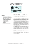
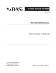
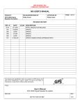
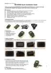
GPS Module SPK-GPS-002RS
SMD type
ROM version
Technical Manual
S.P.K. Electronics Co., Ltd.
.
All right reserved, © 2006
10F, No 510, Sec5.5, Chung Hsiao E.RD.Taipei, Taiwan.
TEL:886-2-23462323 FAX:886-2-23463939
2007, Version 1.0
MADE IN TAIWAN
RoHS compliance.
Contents
1.
Features and introductions……………………………………………………………………………………...1
2.
Performance……………………………………………………………………………..…….…. ……………….2
2.1 Receiver specification……………………………………………….…………………..…………………..2
2.2 Electric specification…………………………………………………………………….…………………..3
2.2.1
Pin assignment………………………………………………………………….…………………..3
2.2.2
Absolute maximum ratings………………………………………………..…. ………………... 4
2.2.3
DC electrical characteristics………………………………………………….…………………..5
2.2.4
Antenna power supply output………………………….…………………….…………………..5
2.2.5
Adaptor antenna……………………………………………………….…….….…………………..6
2.2.6
Input and output timing………………………………………………….…….…………………..6
2.3 Environment specification………………………………………………….…….…….…………………..7
3.
Reference design…………………………………………………………………….….…….…………………..7
4.
Communication specification……………………………………………………………….…………………..8
5.
Foot print……………………………………………………………………………….……….…………………..9
6.
Approved NMEA message…………………………………………….….……..………….………………….10
GGA - Global Positioning System Fix Data…………………………………………….….. ……………….10
GLL - LATITUDE AND LONGITUDE, WITH TIME OF POSITION FIX AND STATUS.…. ………………..11
GSA - GPS DOP AND ACTIVE SATELLITES.….….….….….….….….….….….….………………………..12
GSV - GPS SATELLITE IN VIEW .….….….….….….….….….….….….….….….……….………………….13
RMC - RECOMMANDED MINIMUM SPECIFIC GPS/TRANSIT DATA.….….…..….….…………………..14
VTG - COURSE OVER GROUND AND GROUND SPEED.….….….….….…..….….….………………….15
ZDA TIME AND DATE .….….….….….….….….….….….….….….….….….…...….….….………………….15
Binary Messages.….….….….….….….….….….….….….….….….….….….….….….….………………….15
7.
Evaluation Board……………………………………………………………….…………….………………….16
.
2007, Version 1.0
RoHS compliance.
SPK-GPS-002RS
Fast-Acquisition High-Sensitivity
44-Channel SMD GPS Receiver Module
GPS-002RS is a miniature 44-channel OEM GPS receiver
module. It is optimized for high-performance, ease-of-use,
flexibility, and low-cost. The GPS receiver is suitable for a
wide range of navigation and tracking applications.
FEATURES
z
44 channel to acquire and track
satellites simultaneously
z
SMD type packaging
z
Industry-leading TTFF speed
z
Signal detection better than -158dBm
z
0.5 PPM TCXO for quick cold start
z
SBAS (WAAS/EGNOS) capable
z
Cold start < 35sec
z
Hot start < 1sec
z
Accuracy 5m CEP
z
16 mm L x 13.2 mm W x 3 mm
z
RoHS compliant
44 parallel channels provide fast satellite signal acquisition
and short start-up time. Re-acquisition sensitivity of
-155dBm and tracking sensitivity of -158dBm offers good
performance even under difficult environments.
The GPS-002RS offers a RFIN pad for connecting an active
antenna.
~45mA current consumption and 1sec hot-start TTFF
makes the GPS-002RS ideal for battery-operated portable
devices.
Small size and SMD mounting allow standard SMT
assembly
process,
making
it
ideal
for
volume production.
high
GPS-002RS Evaluation Board
z
GPS-002RS and Evaluation Board
z
USB output adapter board for PC/Notebook
z
USB power/signal cable
z
GPS active antenna (SMA, 3.3V)
z
CD user manual and testing programming
1
.
2007, Version 1.0
RoHS compliance.
2.
PERFORMANCE
2.1 RECEIVER SPECIFICATIONS
Specification
Parameter
Receiver Type
44 channel
Re-acquisition sensitivity
-155dBm
Tracking sensitivity
-158dBm
Cold start sensitivity
-137dBm
Receiver frequency
1575.42MHz
Code
C/A code
Accuracy
(1) Position
(2) Velocity
5m CEP
0.1m/sec
Startup Time
hot start
< 1 sec
warm start
< 10 sec
cold start
< 35 sec
Signal Reacquisition
<1s
Update Rate
1Hz (standard)
Operational Limits
(1) Altitude
< 18,000m
(2) velocity
< 500m/s
Dynamics
4G (39.2m/sec2)
Datum
WGS-84(Default)
Protocol
NMEA-0183 V3.01
2
.
2007, Version 1.0
RoHS compliance
2.2 ELECTRIC SPECIFICATIONS
2.2.1 PIN ASSIGNMENT
NO.
Signal name
I/O
V
Description
1
NC
-
-
Not used.
2
NC
-
-
Not used.
3
1PPS
O
0/3.3
1 pulse per second
4
TXD0
O
0/3.3
Serial data port transmit line
5
RXD0
I
0/3.3
Serial data port transmit line
6
NC
-
-
Not used.
7
NC
-
-
Not used.
8
NC
-
-
Not used.
9
NC
-
-
Not used.
10
ON/OFF
I
0/3.3
11
V-BK
P
3.3
Back up power input
12
VIN
P
3.3
Main power supply
13
NC
-
-
Not used.
14
NC
-
-
Not used.
15
GPS_IND
O
0/3.3
16
NC
-
-
Notes
Turn ON/OFF the GT-755RS
(active Hi)
3.3V
GPS status indicator
Not used.
3
.
2007, Version 1.0
RoHS compliance
NO.
Signal name
I/O
V
Description
17
NC
-
-
Not used.
18
GND
P
0
Ground
19
RF IN
P
3.3
20
GND
P
0
Ground
21
GND
P
0
Ground
22
GND
P
0
Ground
2.2.2
Receive RF signal input
Antenna power supply
Notes
Antenna
spec
ABSOLUTE MAXIMUM RATINGS
Item
Absolute maximum ratings
Unit
ON/OFF input voltage
0~3.3V (Max 6.0V)
V
RXD0 input voltage
0~3.3V (Max 4.0V)
V
V-BK input voltage
0~3.3V (Max 6.0V)
V
VIN input voltage
0~3.3V (Max 6.0V)
V
4
.
2007, Version 1.0
RoHS compliance
2.2.3
DC ELECTRICAL CHARACTERISTICS
Item
Min.
TYP
Max
Unit
ON/OFF
H
Voltage
2.6
-
3.3
V
(Input)
L
Voltage
0
-
0.4
V
TXD0
H
Voltage
2.6
-
3.3
V
(Output)
L
Voltage
0
-
0.4
V
RXD0
H
Voltage
2.6
-
3.3
V
(Input)
L
Voltage
0
--
0.4
V
GPS_IND
H
Voltage
2.6
-
3.3
V
(Output)
L
Voltage
0
-
0.4
V
Voltage
3.0
3.3
3.6
V
Voltage
3.0
3.3
3.6
Current
-
45mA
120mA
V-BK
VIN
Voltage
RF IN
2.2.4
3.3
mA
Notes
@3.3V
V
Impedance
-
50
-
Ohm
Center frequency
-
1.57542
-
GHz
ANTTENNA POWER SUPPLY
The GPS-002RS No.19 pin, RF IN, receives RF signal input and antenna power supply which must be
connected to an external active antenna.
5
.
2007, Version 1.0
RoHS compliance
2.2.5
ADAPTOR ANTENNA
Parameter
Impedance
50 Ohm
NF
1.5dB or less
VSWR
2.0 or less
Element profit
2.2.6
Condition
0dBi or more (at zenith)
-6dBi or more (elevation
Axial ratio
3dB or less
Gain
26dBi~40dBi
Out of band rejection
25dB or more
Operation voltage
3.3V
10 degree)
INPUT AND OUTPUT TIMING
6
.
2007, Version 1.0
RoHS compliance
2.3 ENVIRONMENT SPECIFICATION
Parameter
Temperature
Specification
Operating
-20
~+70
Storage
-40
~+80
Humidity
5%~95%
3. REFERANCE DESIGN
7
.
2007, Version 1.0
RoHS compliance
4. COMMUNICATION SEPECIFICATIONS
Item
Description
Interface
Full duplex serial interface
Bit rate
4800/9600bps
Start bit
1bit
Stop bit
1bit
Data bit
8bit
Parity
none
Transmission data
SACII NMEA0183 Ver:3.01
8
.
2007, Version 1.0
RoHS compliance
5. FOOT PRINT
Unit:mm
TopView
9
.
2007, Version 1.0
RoHS compliance
6. APPROVED NMEA MESSAGE
1
The serial interface protocol is based on the National Marine Electronics Association’s NMEA 0183 ASCII
interface specification. This standard is fully define in “NMEA 0183, Version 3.01” The standard may be
obtained from NMEA, www.nmea.org
GGA - Global Positioning System Fix Data
Time, position and fix related data for a GPS receiver.
Structure:
$GPGGA,hhmmss.sss,ddmm.mmmm,a,dddmm.mmmm,a,x,xx,x.x,x.x,M,x.x,M,x.x,xxxx*hh<CR><LF>
1
2
3
4
56 7 8
9
10
11 12 13
Example:
$GPGGA,060932.448,2447.0959,N,12100.5204,E,1,08,1.1,108.7,M,,,,0000*0E<CR><LF>
Field
1
Name
UTC Time
Example
060932.448
2
Latitude
2447.0959
3
4
N/S Indicator
Longitude
N
12100.5204
5
6
E/W Indicator
GPS quality
indicator
E
1
7
8
9
10
Satellites Used
HDOP
Altitude
Geoid Separation
08
1.1
108.7
11
DGPS Age
12
DGPS Station ID
0000
Description
UTC of position in hhmmss.sss format, (000000.00 ~
235959.99)
Latitude in ddmm.mmmm format
Leading zeros transmitted
Latitude hemisphere indicator, ‘N’ = North, ‘S’ = South
Longitude in dddmm.mmmm format
Leading zeros transmitted
Longitude hemisphere indicator, 'E' = East, 'W' = West
GPS quality indicator
0: position fix unavailable
1: valid position fix, SPS mode
2: valid position fix, differential GPS mode
3: GPS PPS Mode, fix valid
4: Real Time Kinematic. System used in RTK mode with
fixed integers
5: Float RTK. Satellite system used in RTK mode. Floating
integers
6: Estimated (dead reckoning) Mode
7: Manual Input Mode
8: Simulator Mode
Number of satellites in use, (00 ~ 12)
Horizontal dilution of precision, (00.0 ~ 99.9)
mean sea level (geoid), (-9999.9 ~ 17999.9)
Geoid separation in meters according to WGS-84 ellipsoid
(-999.9 ~ 9999.9)
Age of DGPS data since last valid RTCM transmission in
xxx format (seconds)
NULL when DGPS not used
Differential reference station ID, 0000 ~ 1023
NULL when DGPS not used
13
Checksum
0E
Note: The checksum field starts with a ‘*’ and consists of 2 characters representing a hex number. The
checksum is the exclusive OR of all characters between ‘$’ and ‘*’.
10
.
2007, Version 1.0
RoHS compliance
GLL - LATITUDE AND LONGITUDE, WITH TIME OF POSITION FIX AND STATUS
Latitude and longitude of current position, time, and status.
Structure:
$GPGLL,ddmm.mmmm,a,dddmm.mmmm,a,hhmmss.sss,A,a*hh<CR><LF>
1
2
3
4
5
6 7 8
Example:
$GPGLL,4250.5589,S,14718.5084,E,092204.999,A,A*2D<CR><LF>
Field
1
Name
Latitude
Example
4250.5589
2
N/S Indicator
S
3
Longitude
14718.5084
4
E/W Indicator
E
5
6
7
UTC Time
Status
Mode Indicator
092204.999
A
A
8
Checksum
2D
Description
Latitude in ddmm.mmmm format
Leading zeros transmitted
Latitude hemisphere indicator
‘N’ = North
‘S’ = South
Longitude in dddmm.mmmm format
Leading zeros transmitted
Longitude hemisphere indicator
'E' = East
'W' = West
UTC time in hhmmss.sss format (000000.00 ~ 235959.99)
Status, ‘A’ = Data valid, ‘V’ = Data not valid
Mode indicator
‘N’ = Data not valid
‘A’ = Autonomous mode
‘D’ = Differential mode
‘E’ = Estimated (dead reckoning) mode
‘M’ = Manual input mode
‘S’ = Simulator mode
11
.
2007, Version 1.0
RoHS compliance
GSA - GPS DOP AND ACTIVE SATELLITES
GPS receiver operating mode, satellites used in the navigation solution reported by the GGA or GNS
sentence and DOP values.
Structure:
$GPGSA,A,x,xx,xx,xx,xx,xx,xx,xx,xx,xx,xx,xx,xx,x.x,x.x,x.x*hh<CR><LF>
1 2 3 3 3 3 3 3 3 3 3 3 3 3 4
5
6 7
Example:
$GPGSA,A,3,01,20,19,13,,,,,,,,,40.4,24.4,32.2*0A<CR><LF>
Field
1
Name
Mode
2
Mode
3
Satellite used 1~12
4
5
6
7
PDOP
HDOP
VDOP
Checksum
Example
A
Description
Mode
‘M’ = Manual, forced to operate in 2D or 3D mode
‘A’ = Automatic, allowed to automatically switch 2D/3D
3
Fix type
1 = Fix not available
2 = 2D
3 = 3D
01,20,19,13,,,,, Satellite ID number, 01 to 32, of satellite used in solution,
,,,,
up to 12 transmitted
40.4
Position dilution of precision (00.0 to 99.9)
24.4
Horizontal dilution of precision (00.0 to 99.9)
32.2
Vertical dilution of precision (00.0 to 99.9)
0A
12
.
2007, Version 1.0
RoHS compliance
GSV - GPS SATELLITE IN VIEW
Number of satellites in view, PRN number, elevation angle, azimuth angle, and C/No. Four satellites details are
transmitted per message. Additional satellite in view information is send in subsequent GSV messages.
Structure:
$GPGSV,x,x,xx,xx,xx,xxx,xx,…,xx,xx,xxx,xx *hh<CR><LF>
1 2 3 4 5 6
7
4 5 67
8
Example:
$GPGSV,3,1,09,28,81,225,41,24,66,323,44,20,48,066,43,17,45,336,41*78<CR><LF>
$GPGSV,3,2,09,07,36,321,45,04,36,257,39,11,20,050,41,08,18,208,43*77<CR><LF>
Field
1
2
3
4
Name
Number of message
Sequence number
Satellites in view
Satellite ID
Example
3
1
09
28
5
6
7
Elevation
Azimuth
SNR
81
225
41
8
Checksum
78
Description
Total number of GSV messages to be transmitted (1-3)
Sequence number of current GSV message
Total number of satellites in view (00 ~ 12)
Satellite ID number, GPS: 01 ~ 32, SBAS: 33 ~ 64 (33 =
PRN120)
Satellite elevation in degrees, (00 ~ 90)
Satellite azimuth angle in degrees, (000 ~ 359 )
C/No in dB (00 ~ 99)
Null when not tracking
13
.
2007, Version 1.0
RoHS compliance
RMC - RECOMMANDED MINIMUM SPECIFIC GPS/TRANSIT DATA
Time, date, position, course and speed data provided by a GNSS navigation receiver.
Structure:
$GPRMC,hhmmss.sss,A,dddmm.mmmm,a,dddmm.mmmm,a,x.x,x.x,ddmmyy,x.x,a,a*hh<CR><LF>
1
2
3
4
5
6 7
8 9
10 111213
Example:
$GPRMC,092204.999,A,4250.5589,S,14718.5084,E,0.00,89.68,211200,,A*25<CR><LF>
Field
1
Name
UTC time
Example
092204.999
2
Status
A
3
Latitude
4250.5589
4
N/S indicator
S
5
Longitude
14718.5084
6
E/W Indicator
E
7
8
9
10
11
Speed over ground 000.0
Course over ground 000.0
UTC Date
211200
Magnetic variation
Magnetic Variation
12
Mode indicator
A
13
checksum
25
Description
UTC time in hhmmss.sss format (000000.00 ~
235959.999)
Status
‘V’ = Navigation receiver warning
‘A’ = Data Valid
Latitude in dddmm.mmmm format
Leading zeros transmitted
Latitude hemisphere indicator
‘N’ = North
‘S’ = South
Longitude in dddmm.mmmm format
Leading zeros transmitted
Longitude hemisphere indicator
'E' = East
'W' = West
Speed over ground in knots (000.0 ~ 999.9)
Course over ground in degrees (000.0 ~ 359.9)
UTC date of position fix, ddmmyy format
Magnetic variation in degrees (000.0 ~ 180.0)
Magnetic variation direction
‘E’ = East
‘W’ = West
Mode indicator
‘N’ = Data not valid
‘A’ = Autonomous mode
‘D’ = Differential mode
‘E’ = Estimated (dead reckoning) mode
‘M’ = Manual input mode
‘S’ = Simulator mode
14
.
2007, Version 1.0
RoHS compliance
VTG - COURSE OVER GROUND AND GROUND SPEED
The Actual course and speed relative to the ground.
Structure:
GPVTG,x.x,T,x.x,M,x.x,N,x.x,K,a*hh<CR><LF>
1
2
3
4
5 6
Example:
$GPVTG,89.68,T,,M,0.00,N,0.0,K,A*5F<CR><LF>
Field
1
2
3
4
Course
Course
Speed
Speed
Name
Example
89.68
5
Mode
A
6
Checksum
5F
0.00
0.00
Description
True course over ground in degrees (000.0 ~ 359.9)
Magnetic course over ground in degrees (000.0 ~ 359.9)
Speed over ground in knots (000.0 ~ 999.9)
Speed over ground in kilometers per hour (0000.0 ~
1800.0)
Mode indicator
‘N’ = not valid
‘A’ = Autonomous mode
‘D’ = Differential mode
‘E’ = Estimated (dead reckoning) mode
‘M’ = Manual input mode
‘S’ = Simulator mode
ZDA TIME AND DATE
Structure:
$GPRMC,hhmmss.sss,dd,mm.yyyy, , ,xxx<CR><LF>
1
2
3
4 5 6 7
Example:
$GPZDA,104548.04,25,03,2004,,*6C<CR><LF>
Field
Name
1
UTC time
2
UTC time: day
3
UTC time: month
4
UTC time: year
5
Example
104548.04
25
03
2004
6
7
6C
6C
Description
UTC time in hhmmss.ss format, 000000.00 ~ 235959.99
UTC time: day (01 ... 31)
UTC time: month (01 ... 12)
UTC time: year (4 digit year)
Local zone hour
Not being output by the receiver (NULL)
Local zone minutes
Not being output by the receiver (NULL)
Checksum
Binary Messages
See Binary Message Protocol User’s Guide for detailed descriptions.
15
.
2007, Version 1.0
RoHS compliance
7. EVALUATION BOARD
Evaluation Board
Power Switch
USB output connector
SMA active antenna connector
GPS-002FS
USB Output Cable
GPS SMA Active Antenna
16
.
2007, Version 1.0
RoHS compliance
Testing Programming
17
.
2007, Version 1.0
RoHS compliance