1
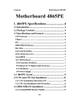
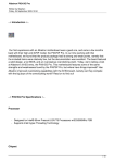
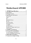
OPTICOM TECHNOLOGIES INC.
.
Vista “L”ite Series DVR
Users Guide
June 2004
1
Opticom Technologies Inc. “L” Series DVR
SAFETY PRECAUTIONS
The exclamation point within an equilateral triangle is intended to alert the user to the
presence of important operating and maintenance (servicing) instructions in the literature accompanying
the appliance
The Lightning flash with arrowhead symbol within an equilateral triangle, is intended to alert the user to
the presence of uninsulated "dangerous voltage" within the product's enclosure that may be of sufficient
magnitude to constitute a risk of electric shock to persons.
2
Opticom Technologies Inc. “L” Series DVR
Table of Contents
1. About the User’s Guide
2. Introduction
3. Equipment Setup Related H/W
3.1 Unpacking (Board Type)
3.1.1 System Requirement
3.1.2 Package Content Per Model
3.1.3 Chipset Comparability
3.2 Unpacking (PC Base System)
3.3 Front of the DVR System
3.4 Back of the DVR System
3.5 Before You Start
4. System Environment Setting
4.1. Power On
5. Current Time Setting
6. Program Start
7. Storage Configuration
7.1 Allocate Hard Drive Space
7.2 Delete Allocated Space
8. Real-Time Monitoring
8.1 Rear-Time Monitoring Screen
8.2 Main Buttons
8.3 Current Time and Status Display
8.4 Screen Split Buttons
8.5Camera Selection/StatusButton
8.6 Sensor / Control Status Buttons
9. Setting Password
10. Basic System Configuration
10.1 Video Source & E-mail Setup
10.2 Camera Rotation & Popup Setting
8
9
11
11
11
11
12
13
14
14
15
16
16
17
18
19
20
21
22
22
23
24
25
26
27
28
29
30
30
3
10.3 Audio Setting
10.4 Analog Video Out Setting
10.5 Sensor & Link Alarm Setting
10.6 Alarm Setting
10.7 Alarm Wave File Setting
11. Video Channel Configuration
11.1 Motion Detection Setting
11.2 PTZ Configuration
11.3 Camera Configuration Setting
11.4 Video Adjust
11.5 Video Quality
11.6 Alarm Sound & E-mail Link Setting
12.Recording/Schedule/Configuration
12.1 Pre-Post Alarm Record
12.2 Recording Schedule Configuration
12.3 Recording Schedule
13. Network Configuration
13.1 Server Configuration
13.2 User Registration
13.3 Current Session
14. ID Setup
15. PTZ Setup
15.1 Button description
16. Recording Data Search
16.1 Calendar & Playback
16.2 Payback Data Search Window
17. Detail Search
17.1 Detail Search Screen
17.2 Digital Zoom In/Out and Enhancement
17.3 Still Image Print& Save
18. Panorama Data Search
19. Video Clip Backup
20. Client Program Installation
21. Remote Monitoring
21.1 Client Program Description
21.2 Remote Client Features
21.2.1 Connection Screen
21.2.2 Recorded Data Search
31
32
32
33
33
34
35
36
36
37
37
37
38
38
39
42
45
46
48
49
50
51
52
53
54
55
56
56
57
58
60
62
63
64
64
68
68
69
4
21.2.3 Server Setting
21.2.4 PTZ Control
22. Web Remote Client
23. Troubleshooting Guide
24. Customer’s Responsibilities
25. Manufacturer’s Responsibilities
26. Safety Summary
70
71
72
73
79
79
80
Opticom Technologies Inc. “L” Series DVR
1. About the User’s Guide
This User’s Guide is designed for end users, installers and technical support.
.
● End User : If a user is able to perform basic operations or has basic knowledge about
computers, he/she can understand and use most of the functionality of the DVR by simply
following the instructions in this User’s Guide.
.
● Installer : If an installer has basic knowledge of the hardware structure of a DVR,
he/she can easily understand most of the Vista “L” Series DVR’s functionality by following the
instructions in the User’s Guide and he/she will be able to set the system according to the end
user’s request.
* This User’s Manual does not include explanations of peripheral
equipment such as cameras, pan/tilt equipment, monitors, computers,
network equipment, etc.
● Technical Support : Tech support can understand most of the functionality if he/she
follows the instruction of the User’s Guide for the Vista “L” Series .DVR, and he/she
can offer advice to the end user or installer on their inquiries.
* This User’s Manual does not include explanations of peripheral equipment
such as cameras, pan/tilt equipment, monitors, computers, network
equipment, etc.
This User’s Guide explains how to set-up and operate the product from the moment
the box is opened.
The following is a list of the contents of the guide
-Equipment and System Environment Setup and Safety Instructions
-Main Server Application (Vista “L” Series DVR) Operations
-Client Application (Vista “L” Series Remote PC) Setup and Operations
-Warranty and Responsibility
5
Opticom Technologies Inc. “L” Series DVR
2. Introduction
The Vista “L” Series DVR series is an advanced digital video monitoring and recording
system that converts analog video signals into digital data, displays the digital video on
computer monitors in real time, stores it onto permanent storage such as hard disks with high
compression ratio, and transmits it through the Internet. It also generates credible alarms
using state-of-the-art image processing techniques. The Vista “L” Series features are:
.
●Various split display modes (1, 4, 9, 16 equally split display or 6, 8, 10, 17 focused split
display)
.
●Easy select & backup facilities -still image and AVI video clip (Neo Drive, CD-ROM,
Removable Hard Disk, DVD, etc.)
.
●Convenient search features – our patented VisualCue® recording map shows a colorcoded recording history divided per camera. At a glance our patented VisualCue® recording
provides an easy way of searching with date/time/camera/event. Our state-of-the-art Instant
Visual Check scrollbar enables random access with instant visual checking and the panoramic
temporal search shows snap-shots for specific camera to analyze every scene. 2-times and 4-times
fast video replay are also available.
.
●Remote pan/tilt/zoom control and remote program configuration – the Vista “L” Series
client program fully controls the Vista “L” Series server program through the Internet.
.
●Remote video monitoring in real-time, remote searching and replaying through the
Internet.
.
●Highly compressed recording of high resolution images (320×240 or 640×480,
compressed up to 1~6 KB per frame)
.
●E-mail alarm – E-mails are sent when there is motion in front of the camera or sensors.
Since the e-mail contains the image taken at the time, the user can discern what was happening.
The e-mail can be transferred to a mobile phone if there is an E-mail-to-Mobile link.
The strengths of the Vista “L” Series are:
●Non-stop operation along with patented technologies.
-Anti-Frag® File System prevents disk fragmentation from to
frequent hard disk writes. -Watchdog Function continuously
checks up the system and recovers it from unexpected system
failure. -The 10-Segment Reliability Test Program guarantees
highly reliable products.
6
Opticom Technologies Inc. “L” Series DVR
● Rapid and flexible customization capability and high compatibility with analog CCTV
systems. -Object-oriented programming and component software technology enable rapid
completely reflecting customer requirements.
-High compatibility with analog CCTV systems promotes the reuse of existing analog
CCTV equipment.
.
● User-friendly and efficient working environment.
- Various split-screen modes facilitate intensive and focused monitoring.
-Visual metaphor functions such as VisualCue®, Temporal Panorama, and Slide Bar
control enable fast and powerful search.
-Video clips and still images of interest can be stored as a backup in well-known formats on
various media such as Neo Drive, CD-RW, Removable Hard Disk, DVD-RW, DAT, and
analog video.
● Real-time remote monitoring and control through the Internet.
-Network-version client software enables real-time remote monitoring and searching,
remote pan/tilt/zoom control, and remote configuration.
-Web-version client software enables real-time remote monitoring and searching, remote
pan/tilt/zoom control with only a web browser.
● High-speed display, high-performance compression, and anti-forgery watermark adoption
- DMA data transfer and AGP enable high-speed real-time video display.
-Our unique Adaptive MPEG-4 algorithm for video data compression remarkably
prolongs the recording period.
-Our efficient and fast watermarking technology protects the recorded video against
malicious forgery.
7
Opticom Technologies Inc. “L” Series DVR
3. Harware Setup
3.11
Unpacking (Board Type)
3.1.1 System Requirements
Minimum Requirement
CPU
Recommended
Intel Celeron 1.7 GHz equivalent
O/S
Intel P-4 1.8 GHz or faster
Windows 2000 series, Windows XP series
Memory
128 MB
256MB or more
HDD Space
40 GB
80 GB or more
VGA Card
ATI Radeon 7000 64MB or higher DDR
3.1.2 Package Content Per Model
Capture Board Type Model
Intel CPU
compatible
chipset
AMD CPU
compatible
chipset
VGA Card
VSL430
VSL1630
VSL16120
VSL16240
VSL16480
VSL16480B
VSL16480C
Intel i845PE
OK
OK
OK
OK
OK
OK
OK
Intel i865PE
OK
OK
OK
OK
OK
OK
OK
Intel i875P
OK
OK
OK
OK
OK
OK
OK
VIA P4X400
OK
OK
N/A
N/A
N/A
N/A
N/A
VIA PT800
OK
OK
N/A
N/A
N/A
N/A
N/A
SiS 645
OK
OK
OK
OK
N/A
N/A
N/A
SiS 658
OK
OK
OK
OK
OK
OK
OK
SiS 748
OK
OK
OK
OK
OK
OK
OK
VIA KT400
OK
OK
OK
OK
OK
OK
OK
VIA KT600
OK
OK
OK
OK
OK
OK
OK
ATI Radeon 7000
SDR 32M
OK
OK
OK
OK
OK
OK
OK
ATI Radeon 7000
DDR 32M
OK
OK
OK
OK
OK
OK
OK
ATI Radeon 7500
DDR 128M
OK
OK
OK
OK
OK
OK
OK
8
Opticom Technologies Inc. “L” Series DVR
3.2 Unpacking (System Type)
DVR Main System
Keyboard
Mouse
Handles
Power Cable
Application CD
Manual
Computer Case Keys
9
Opticom Technologies Inc. “L” Series DVR
3.3 Front of the DVR System
1
1)
2)
3)
4)
5)
6)
2
3
4
5
6
Power LED: Indicates if the power is ON?OFF.
Run LED: Displays the status of the system.
HDD(Hard Disk Drive) LED: A lamp indicating the operation of the HDD
Power Switch: Turns the DVR system on or off.
FDD: Image Retrieval (Option)
CD-RW: Recover DVR system and back up video (Option)
10
3.4 Back of the DVR System
1
6
1)
2)
3)
4)
5)
6)
7
Camera Inputs 1 – 16
Sensor Connections
A/V Out Connector
Alarm Out Connector
Audio Input Connector
Power Plug
2
8
3
9
4
10
5
11
12
7) Mouse Connector
8) Keyboard Connector
9) Serial Communication Port (Com1, Com2)
10) Parallel Port
11) Video Connector
12) Lan Connection
Opticom Technologies Inc. “L” Series DVR
3.5 Before You Start
Make sure you have access to three standard grounded outlets and a flat level surface to support
the main system. Proper grounding is essential for user safety and proper DVR operation.
Before you install the Vista “L” Series DVR properly, you should prepare the following
equipment:
SVGA video monitor
CCTV cameras
Coaxial cable
1.
1. This system is not explosion-proof. Therefore, it is not to be used in the presence
of flammable material.
2.
2. Proper use of this device depends on careful reading of all instructions and labels.
3.
3. Keyboard and mouse connectors to the main system
Connect the keyboard and mouse to the back of the main system.
DVR system may not be operated if the Key Board and Mouse are not connected
proper way.
11
4. Video monitor cable to the main system
Connect the video monitor cable to the main system by inserting one end of the
9-pinconnecting cable into the back of the main system.
5. Video monitor cable to video monitor
Connect the video monitor cable to the video monitor by inserting one end of the
9-pin connecting cable into the back of the video monitor.
6. Coaxial video cable to the main system
Connect the coaxial video cable to the main system by inserting one end of the
BNC connecting cable into the back of the main system.
7. Coaxial video cable to the cameras
Connect the coaxial video cable to the cameras by inserting one end of the BNC
connecting cable into the back of the camera.
8. Video monitor power cord to outlet
Plug the video monitor power cord into a grounded wall outlet.
9. Main system power cord to outlet
Connect the main system power cord to a grounded wall outlet
12
Opticom Technologies Inc. “L” Series DVR
4. System Environment Setting
4.1. Power On
1) After setting up the hardware, turn on the power switches to the main system,
monitor, camera, and other devices connected with the Vista “L” Series DVR.
Wait a few moments for the display to appear. The system performs a self-test and
displays a message if any errors are found. Call the OPTICOM TECHNOLOGIES
Technical Support.
if error messages are displayed (E-mail: [email protected]),
Phone: 1-888-367-2288
When the self-test is finished, the main screen appears.
The Vista “L” Series model determines the number of video windows in the main
screen.
For example, Displays 16CH video windows. The main screen display that you
first see when you power up is:
Please check your power supply mode before “power on”
13
Opticom Technologies Inc. “L” Series DVR
5. Current Time Setting
Because the Vista “L” Series DVR System is using the Windows system time, the time already set
at the factory needs to be set again with the appropriate time according to the user’s geographic
location.
Step 1) Click Settings Button Step 4) “System Time Setup “ Click
Step 2) Enter Password (default -“0”) and
click “Enter” Step 5) Set the time
for the location Press “Apply” and
“OK” to finish
14
Opticom Technologies Inc. “L” Series DVR
Step 3) “Data Storage Setup” Button Click
15
Opticom Technologies Inc. “L” Series DVR
6. Program Start
Step 1) In the Windows main screen, click “Start” → “Programs →
“Vista “L” Series DVR” Click
Step 2) Auto Update
Step 3) Main Screen
16
Opticom Technologies Inc. “L” Series DVR
7. Storage Configuration
: Add or delete allocation space of the hard drive for recorded video data.
* Available Hard
* Total Hard Drive Space
* Used Hard Drive
* To overwrite hard disk drive, check this box.
If this box is not checked, recording is stopped after HDD gets full (100%).
17
Opticom Technologies Inc. “L” Series DVR
7.1 Select Hard Drive Space for Recording
18
Opticom Technologies Inc. “L” Series DVR
Step 1) Click Setting Button
19
Opticom Technologies Inc. “L” Series DVR
8. Real-Time Monitoring
8.1 Real-Time Monitoring Screen
#1) Video Input Status.
#2) Recording Status.
#3) Date/Time Mode.
#4) HDD Capacity Indicator.
#5) Camera Display Status.
#6) Screen Split
#7) Video Search.
#8) Pan/Tilt Control.
20
Opticom Technologies Inc. “L” Series DVR
8.2 Main Buttons
1
1 Video Search
2 Setup
2
3
4
Click to search recorded video data. There are two types
of search: general search and detailed search.
Click to setup the Vista L Series DVR. There are 6 types
of system settings.
3 Pan/Tilt Control
Click to move the camera up/down, left/right, to focus, to
enlarge to reduce.
4 Exit
Terminate the main program or the system. Type
password to confirm the termination.
System Reboot: Terminate application and reboot system
Exit Application: terminate the Vista L Series DVR
server and return to windows.
System Poeroff: Exit application and power down the
system
[Password Confirm]
[Termination Options]
21
Opticom Technologies Inc. “L” Series DVR
8.3 Current Time and Status Display
Current Time and Date
Current time and date should be setup correctly for accurate
video recording.
The playback of the video is performed according to this time and date.
In order to setup date and time, use either the BIOS setup before
system booting or the date/time applet in the control panel of Windows.
-Playback & Search Mode -Detailed Search Mode -System Configuration Mode -Pan/Tilt Control
Mode
22
Opticom Technologies Inc. “L” Series DVR
8.4 Split Screen Buttons
The selected split screen icon is green. According to
the DVR model, available screen split modes are as
follows:
Equally Split Screen
Focused Split Screen
Alternating Display and Full Screen Display
23
Opticom Technologies Inc. “L” Series DVR
8.5 Camera Selection/Status Buttons
In surveillance mode, each button corresponds to
a camera. Clicking the camera button will display
the corresponding camera in the main view.
In Playback and Search Mode, select a camera for
detailed search.
Camera Status Display
Camera status is displayed as follows.
•
•
•
Active Camera &
Main View
Camera
•
•
This camera indicates that the camera is activated. In other wards,
the camera is currently displayed on the screen
This icon indicates the camera is displayed in the Main View
(Gray with Black Number)
This icon indicates the camera is inactive. In other words the
camera cannot be seen on the screen.
(Gray with White Number.
Inactive Camera
•
Icon turns to “Yellow” under recording search or PTZ.
Recording Search
& PTZ Camera
24
Opticom Technologies Inc. “L” Series DVR
8.6 Sensor/Control Status Buttons
Displays the sensor input status and control output.
The light is on when the sensor input is activated. Active Sensor Input
The light is on when the control is activated. Active Control Output
25
Opticom Technologies Inc. “L” Series DVR
9. Setting Password
26
Opticom Technologies Inc. “L” Series DVR
10. Basic System Configuration
27
Opticom Technologies Inc. “L” Series DVR
10.1 Video Source & E-mail Setup
* Sensor or Motion triggered channel pops up in a large screen.
Adjust for length of time in seconds.
28
Opticom Technologies Inc. “L” Series DVR
*Windows Sound and
Audio Devices Properties
open up.
Click “OK” to exit.
29
Opticom Technologies Inc. “L” Series DVR
10.4 Analog Video Out Setting
* Analog Video out Rotation Interval
* Select cameras to view through analog
video out. -Default : Select all cameras -Reset
: Unselect all cameras
10.5 Sensor & Link Alarm Setting
Connect up to 8 sensors.
*Name individual sensors.
* Select sensor type.
*Select alarms trigger when sensor
is triggered.
VSL430-cs, VSL1630-cs, VSL16480-cs only support 4 alarms.
30
Opticom Technologies Inc. “L” Series DVR
10.6 Alarm Setting
Connect up to 8 alarms.
Name individual alarms.
Select duration of the alarm.
(1 ~ 180 seconds)
10.7 Alarm Wave File Setting
Select wave file to be played
for motion detection.
Select wav file to be played
for sensor detection.
4 wav files are included in the
default system. You can select
other wav files in other
locations if desired.
31
Opticom Technologies Inc. “L” Series DVR
11. Video Channel Configuration
: Settings for Motion Detect, Recording Quality, Camera Display, PTZ, Alarm Sound
and E-mail.
* Click “ALL” button to select or un-select all cameras.
32
Opticom Technologies Inc. “L” Series DVR
11.1 Motion Detection Setting
Current view of selected camera.
Set motion detection sensitivity
and region.
Motion detection region application size.
(PEN size: PEN1 < PEN2 < PEN3)
Show/Hide motion detection region on
the view screen.
Remove all previous regions.
Apply current region setting.
.
Sensitivity ( 0 ~ 10 )
33
Opticom Technologies Inc. “L” Series DVR
11.2 PTZ Configuration
* Select connected port. * Select PTZ address
11.3 Camera Configuration Setting
34
Opticom Technologies Inc. “L” Series DVR
11.4 Video Adjust
Adjust video display /
recording properties.
.
11.5 Video Quality
Recording quality settings.
11.6 Alarm Sound & E-mail Link Setting
Enable Alarm Sound
notification
Enable Email notification.
35
Opticom Technologies Inc. “L” Series DVR
12. Recording Schedule Configuration
Setup recording schedule, recording frame rate, pre-alarm and post alarm.
* Click “ALL” button to select or un-select all cameras.
36
Opticom Technologies Inc. “L” Series DVR
12.1 Pre-Post Alarm Recording Time Setting
* When Motion or Sensor recording is selected, pre-alarm and post-alarm recording is
possible up to 5 seconds.
Pre-Post Alarm applies to all the cameras regardless of recording schedule.
12.2 Recording Schedule Configuration
If checked, selected camera and timeframe will be recorded
continuosly.
If checked and motion region is set, selected camera and
timeframe will be recorded when motion is detected.
If checked, selected camera and timeframe will be recorded
when applicable sensor is triggered,
Motion & Sensor Detection can be checked together for
recording under either conditions.
37
Opticom Technologies Inc. “L” Series DVR
Sensor connected to the cameras.
If external light is attached to the camera,
the light will be powered on selected
camera and timeframe.
Alarm Sound and Email notification will
operate when motion or Sensor is
detected.
( Alarm Sound & Email need to be
setup beforehand. )
Click “Reset” to clear all recording
schedules.
.
38
Opticom Technologies Inc. “L” Series DVR
39
Opticom Technologies Inc. “L” Series DVR
12.3 Recording Schedule example
Continuous Recording
2) Motion Detection Recording Schedule
40
Opticom Technologies Inc. “L” Series DVR
4) Motion & Sensor Detection Recording Schedule
41
Opticom Technologies Inc. “L” Series DVR
5) Continue + Light ON + Alarm ON Recording Schedule
6) Motion & Sensor Detection + Light ON + Alarm ON Recording Schedule
42
Opticom Technologies Inc. “L” Series DVR
13. Network Configuration
* Configure the network and clients
43
Opticom Technologies Inc. “L” Series DVR
13.1 Server Configuration
.* Server Name, IP Address, Client Video Transmission Quality configuration.
Enter DVR Server name.
Open “Network Connections”
(View page 46 for more info. )
Current IP address
Enable Web browse client
TCP Service can be any number
Between 1200 and 9999.
Video transmission quality
through network.
44
Opticom Technologies Inc. “L”
Series DVR
Open “Network Connections” window to
configure network.
Step 1) Right click on Local Area Connection
And click “Properties”.
Step 3) Fill in appropriate values in the
following window. Click “OK”
Step 2) Select “Internet Protocol (TCP/IP)” and click “Properties”
45
Opticom Technologies Inc. “L” Series DVR
13.2 User Registration
* Enter ID and Password for Client to connect to Server.
Enter User Id.
Enter Username.
Enter Password.
Select User Level.
Live monitoring.
Live monitoring and playback.
Live monitoring, playback and configuration.
Click “ADD” to add a new user.
Click “UPDATE” to edit existing user.
Click “DEL” to delete a user.
46
Opticom Technologies Inc. “L” Series DVR
13.3 Current Session
* Shows current Client connection and Client’s information.
disconnection of Client
47
Opticom Technologies Inc. “L” Series DVR
14. ID Setup
* Change Password
48
Opticom Technologies Inc. “L” Series DVR
15. PTZ Setup
* Operation of PTZ cameras.
49
Opticom Technologies Inc. “L” Series DVR
15.1 PTZ Button Description
Pan / Tilt control button :
A button to control the direction of the camera ( Up, Down, Left
and Right)
Image Zooming in/out control button:
Used to zoom in and out of selected image
Focus Control button:
Used to control the focus of the selected camera.
Wiper On/Off switch:
Used to run/stop the operation of the wiper for cameras which are
installed outside the location.
Outside Light Switch button:
Used to turn On/Off the housing light installed outside.
Power switch button:
Used to turn on/off power of peripherals like a fan.
Set/release button at the starting/end point:
Setting/releasing the starting and ending point of the automaticturning of the camera.
Automatic-turning switch:
Used to start/stop the auto-turning base
50
Opticom Technologies Inc. “L” Series DVR
16. Recording Data Search
* Playback, Search and Back up recorded data.
51
Opticom Technologies Inc. “L” Series DVR
16.1 Calendar & Playback
Calendar
Select the Year and month of interest, then
the color coded dates are shown.
limited to the range you selected earlier.
.
Play: Play the selected video
Fast Play: Fast forward play the selected video
Next Image: Go to next image frame.
Pause
Random Access Slider:
As the slider moves, the video plays in high speed. So, you can skim over
the entire selected video to find out events of interest.
52
Opticom Technologies Inc. “L” Series DVR
16.2 Recorded Data Search Window Example
Display the selected date
Denotes camera number
* Video recording status map shows the video
recording status; the column denotes channels and the
row denotes the time.
One row represents a 30 minute time slot. You can
select time-camera zones by using the keyboard or
dragging the mouse. When you use the keyboard, the
starting time is set by the up/down arrow key with the
SHIFT key, and the stop time by the up/down arrow
key with the CTRL key.
Right click within 60 minute search
window to select different type of
recording to be displayed.
53
Opticom Technologies Inc. “L” Series DVR
17. Detail Search
Color Adjustment
Play
Button
Restore
Zoom Panning
In/Out
Thumbnail
Images
54
Opticom Technologies Inc. “L” Series DVR
17.2 Digital Zoom In/Out and Image Enhancement
Restore:
The image is restored to its original state. All the zooming and
moving actions are rolled back.
Zoom In/Out:
With the zoom in/out icon selected, place the cursor on the image
region you want to zoom in on and drag it to the right. The region is
zoomed in. Dragging to the left performs zoom out.
[Zoom In]
[Move Up/Down]
[Zoom Out]
[Move Left/Right]
55
Opticom Technologies Inc. “L” Series DVR
17.3 Still Image Print & Save
Preview Selected Image:
Preview the selected image. Here, you can set up
the print layout
[ 1x2 Layout]
[ 2x4 Layout]
[ 4x8 Layout]
Selected Print:
Print the selected image.
You can preview them with the “Preview” function.
.
56
Opticom Technologies Inc. “L” Series DVR
Save selected image:
Save the selected image onto a disk.
Show/Hide Thumbnail Image:
Show or hide the thumbnail images on the screen
57
Opticom Technologies Inc. “L” Series DVR
18. Panorama Data Search
58
Opticom Technologies Inc. “L” Series DVR
59
Opticom Technologies Inc. “L” Series DVR
19. Video Clip Backup
* Year, Month and Date :
Select the date of the video
on which a video clip is made.
* Channel Select :
Select the channel of the video on
which a video clip is made..
Backup Start Time
Backup Stop Time
Backup Location.
Available free space.
Codec selection.
* Make AVI File:
Make an AVI file for
Selected time period
* Quit Backup
Quit backup operation
60
Opticom Technologies Inc. “L” Series DVR
20. Client Program Installation
61
Opticom Technologies Inc. “L” Series DVR
1.
21. Remote Monitoring
2.
21.1 Starting Client Program
Step 1) “My Computer”
double click “C:/OpticomtechDVRs/OpticomTechdvrs.exe”
62
Opticom Technologies Inc. “L” Series DVR
Step 4) Following window will open once password is entered.
63
Opticom Technologies Inc. “L” Series DVR
Step 5) Enter Server information to the screen below and click “ADD”. Click on Exit Button at
the bottom to exit.
Setup 6) Click Connect Button to connect.
64
Opticom Technologies Inc. “L” Series DVR
Step 7) Enter User ID and Password and click “CONNECT” to start Client program.
65
Opticom Technologies Inc. “L” Series DVR
21.2 Client Features
21.2.1 Main Client Screen
Description
66
Opticom Technologies Inc. “L” Series DVR
21.2.2 Recorded Data Search in Client
Playback Screen
* Calendar
* Video Playback Control
67
Opticom Technologies Inc. “L” Series DVR
21.2.3 Server Setting change in Client
68
Opticom Technologies Inc. “L” Series DVR
21.2.4 PTZ control through Client Software
69
Opticom Technologies Inc. “L” Series DVR
22. Web Client
70
Opticom Technologies Inc. “L” Series DVR
23. Trouble Shooting Guide
1) ‘No Video Signal’ message on the screen.
-Check camera input connector.
-Check camera power supply.
* Contact camera supplier for further troubleshooting.
2) Frozen Screen or screen shake in black and white.
-Check video input type (NTSC / PAL).
-Check if the connected camera is NTSC or PAL.
3) DVR time does not match current time. -DVR
time is set by Windows time. -Set time in BIOS or
Windows to correct time (Windows time can be set in
NeoWatch under Settings.) -Changing time during
recording could damage the data.
4) ‘Neo Watch’ image instead of video. -Check if that particular camera is
enabled. -Check if that particular camera’s display is enabled.
71
Opticom Technologies Inc. “L” Series DVR
5) Sensor malfunction.
-Check for secure sensor connection at the sensor input.
-Check power supply to sensor.
-Check if that particular sensor is enabled in the setting.
-Check if sensor type is entered correctly.
6) Alarm malfunction with motion detection.
-Check for secure alarm connection at the alarm input.
-Check power supply to Alarm.
-Check if that particular alarm is enabled in the setting.
-Check if motion detection region is set for that particular camera. -Check if Alarm is enabled
in the Schedule for that particular camera.
7) Alarm malfunction when connected to sensor.
-Check sensor (see number 5)
-Check alarm (see number 6)
8) Alarm operation is too short.
-Increase Alarm operation time up to 180 seconds.
72
Opticom Technologies Inc. “L” Series DVR
9) Motion detection malfunction.
-Check if motion detection region is set for that particular camera. –Motion detection region
setting instruction
* Select desired PEN size and hold down mouse button and ‘paint’ desired area. (Set 0 –
10 for sensitivity. Recommend ‘8’)
10) Display screen properties change. (color, brightness, etc.)
-Slide video property bar to set desired setting. (default setting is usually optimal)
11) No e-mail notification for motion detection.
-Check if e-mail address is correct. -Check if e-mail server
setting is correct. (contact your network administrator or your
ISP for further assistance.)
12) No e-mail notification for sensor detection.
-Check if sensor is operating correctly and AlarmEmail is checked.
-Check if e-mail address is correct.
-Check if e-mail server setting is correct.
(contact your network administrator or your ISP for further assistance.)
73
Opticom Technologies Inc. “L” Series DVR
13) No recording.
-Check schedule for desired recording schedule.
-Recording schedule setting instruction. * Continuous Recording: Continuous recording
during selected day and time.
* Motion Detection Recording: Recording only when
motion is detected during
selected day and time.
* Sensor Recording:
Recording only when sensor is triggered during selected day
and time.
14) No recording in Continuous mode. -Check recording schedule for desired recording day
and time.
15) No recording in Motion Detection mode during movement.
-Check sensitivity.
-Check recording schedule for desired recording day and time.
16) No recording in Sensor Recording mode when sensor is triggered. -Check sensor setting
and type. -Check camera and sensor link selection. -Check recording schedule for desired
recording day and time.
17) Poor recording quality.
-Increase Video Quality in setting.
74
Opticom Technologies Inc. “L” Series DVR
18) Choppy playback.
-Increase frame rate in the Recording Schedule. (Increasing the frame rate
decreases the total recording time. Check required frame rate and total
recording time and adjust appropriately.)
19) No display screen rotation even when the rotation time is set.
-Check if rotation button is pressed in the main screen.
20) No video in the external analog monitor
-Check for secure connection between the monitor and DVR.
-Check power supply of the monitor.
-Check if Analog Video is enabled.
21) Random display of large screen in the main screen.
-Check if Popup is enabled.
-Popup feature will show the channel where motion is detected in the main screen.
75
Opticom Technologies Inc. “L” Series DVR
22) PTZ control malfunction.
-Check for secure connection of the PTZ camera.
-Check for correct controller connection.
-Check for correct PTZ controller type and protocol.
-Check for correct COM port selection for that particular PTZ controller.
(contact camera supplier for further troubleshooting.)
23) Cannot view playback or change settings through Client software.
-Check for appropriate user level for playback and settings configuration. -Change the user
level to desired level in the Server.
76
Opticom Technologies Inc. “L” Series DVR
24. Customer’s Responsibility
This product and its components will perform reliably only when operated and
maintained in accordance with the instructions contained in this manual,
accompanying labels, and/or inserts. A defective product should not be used. Parts
which may be broken or missing or are plainly worn, distorted or contaminated should
be replaced immediately with clean, genuine replacement parts manufactured by or
available from Opticom Technologies Inc. The responsibility of Opticom
Technologies Inc for a defective product is limited by the warranty set forth in this
manual. Should repair or replacement of this product become necessary after the
warranty period, the customer should seek advice from Opticom Technologies Inc
prior to such repair or replacement. If this product is in need of repair it should not be
used until all repairs have been made and the unit is functioning properly and ready
for use. The owner of this product has sole responsibility for any malfunction
resulting from improper use or maintenance, or repair by anyone other than Opticom
Technologies Inc, and from any malfunction caused by parts that are damaged or
modified by anyone other than Opticom Technologies Inc
25. Manufacturer’s Responsibility
Opticom Technologies Inc or its authorized representative is responsible for the effects on
safety, reliability and performance of Vista “L” Series DVR only if:
Repairs or modifications to Opticom Technologies Inc.are made by OPTICOM
.
TECH authorized personnel.
The electrical installation provided for the Opticom Technologies Inc.at the
customer site complies with the appropriate local electrical regulations. For example, in Europe,
the
“Regulations for the Electrical Equipment of Buildings” published by the Institution of
Electrical Engineer shall be followed.
.
Opticom Technologies Inc.is used in accordance with the instructions for use.
77
Opticom Technologies Inc. “L” Series DVR
26. Safety Summary
Two labels are used in this manual to identify potentially dangerous conditions or procedures.
WARNING and CAUTION messages must be strictly observed.
WARNING identifies conditions or practices that may present danger to the user.
CAUTION identifies conditions or practices that could result in damage to the
equipment.
The following safety precautions must be observed during the operation of the system to
avoid the possibility of injury.
This system is not explosion-proof. Therefore, it is not to be used in the presence of flammable
materials.
This equipment utilizes a three-wire power cord. The chassis is earth-grounded. Inspect
the power cords
periodically for fraying or other damage.
Do not operate the apparatus with a damaged power cord or plug.
Be sure the switches to the main system, monitor, and cameras are OFF and they are unplugged
before you begin cabling.
Be sure power is OFF when connecting or disconnecting the camera. Do not connect or
78
disconnect the camera when power is on; Damage may result.
Usage
1) Power Cord: Make sure that it is not placed under any heavy objects, such as a monitor.
To disconnect the cord, pull it out by the plug. Pulling the cord itself may cause
stripping or cutting, which may result in electric shock.
To avoid electric shock, always dry your hands before plugging or unplugging
Opticom Technologies Inc. “L” Series DVR
2) Always keep the DVR off the foreign objects.
3) Any modifications such as changing the HDD , installation of modem, etc. will be
recommended to be serviced through OPTICOM TECH Co.,Ltd or any authorized branch
office. Modifications conducted by any unauthorized parties may cause void in the
warranty and improper after service.
4) In case of any problems while using the product, it is prohibited for any unauthorized
personnel or end-user to take the unit apart and/or re-install the unit. Must contact any
OPTICOM TECH office for all after service and technical support
5) A protective seal will be placed on the DVR for various reasons and shouldn’t be tampered
with. It may void the warranty and a standard after service of the DVR. will not be conducted
if the seal is tampered with.
6) Never open and modify the DVR while it is on
7) Each DVR has an AIR FILTER on the front right side to prevent dust and is installed for
better performance of the fan. For any normal condition, cleaning the air filter is required only
once every 2 weeks depending on the amount of dust in the area which may require frequent
cleaning of the filter To replace a damaged air filter, contact the customer service or the
referred agents
8) Error may occur during natural disasters such as thunder and lightering storm.
9) If not used for on extended period of time, keep the DVR unplugged, for safety.
Setup
1) Heat
Do not install DVR in an air-tight area. For the air circulation, make sure the holes on the DVR
case are not covered or blocked. Increasing the temperature of the DVR from a low air circulated
area, it may cause the system to go down.
Do not remove the rubber pegs off the DVR . These are for the air circulation and to protect the
79
bottom of the unit.
2) To prevent any instability. Do not drop or place materials such as heavy objects, liquids, high
voltage materials, etc. The HDD is weak in taking shock.
3) Installation of DVR must be made by OPTICOM TECHNOLOGIES INC.or the authorized
agents.
Opticom Technologies Inc. “L” Series DVR
Handling
1) The products weigh 23kg and is very fragile. Dropping a DVR may cause the unit to
break or may cause serious injuries. Must handle with extreme care when handling the
DVR out of box.
2) When shipping the DVR to a far location, please pack the DVR with the appropriate
padding and other protective materials as is. Shipping or carrying the DVR unit without
its protective packaging materials, may cause damage to the DVR. HDD is weak in shock
3) When returning or shipping the DVR, the units must be packed in the original
condition. Damages may be cause to the DVR if packed in other boxes.
4) Chemicals : Avoid exposure to insecticide, thinner or other flammables.
Danger of explosion if battery is incorrectly replaced.
Replace only with the same Lithium Battery in the mother Board.
Dispose of used batteries according to manufacturer’s instructions.
Proper use of this device depends on careful reading of all instructions and
labels
Specifications on the User’s Guide are made in February, 2004 and subject to
change without notice. Please contact OPTICOM TECHNOLOGIES INC.
80
and/or authorized agents with any questions
81