1
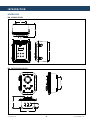
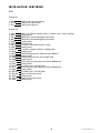
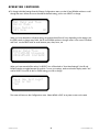
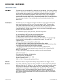
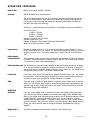
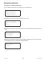
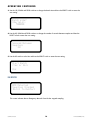
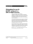
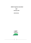
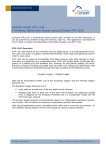
An ISO 9001 certified company
KAM® SC SAMPLER CONTROLLER
PER API 8.2, ASTM D4177
AND ISO 3171
User Manual
SCMANUAL-0613
TEL +1 713 784-0000
FAX +1 713 784-0001
Email [email protected]
KAM CONTROLS, INC.
3939 Ann Arbor Drive
Houston, Texas 77063 USA
www.KAM.com
TABLE OF CONTENTS
SECTIONTITLEPAGE
1 Introduction •Mounting Options
•Theory of Operation
•Features
•Applications
2
2
3
3
3
2 Specifications
•Specifications
4
4
3 Installation
5
•Typical Sampling System
5
•Wiring
6
4 Operation
8
•User Interface
8
•Main Menu
8
•Change Configurations Menu
8
•Configurations Settings
10
•Start New Batch (Automatic)
12
•Start New Batch (Manual)
13
•Emergency Manual Override
14
KAM CONTROLS, INC. reserves the right to make changes to this document without notice.
SCMANUAL 0313
1
KAM CONTROLS, INC.
INTRODUCTION
MOUNTING OPTIONS
FIG. 1-1 NEMA IV ENCLOSURE
6.0
7.4
9.4
Kam
Controls
R
Incorporated
3939 Ann Arbor Drive
Houston, Texas 77063
USA
Tel. 713 784 0000
Fax. 713 784 0001
Sampler Controller
11.9
MENU
SELECT
FIELD
UP
DOWN
EXIT
10.75
www.Kam.com
2.50
2.50
3.75
9.53
10 5/8 MTG. CEN
FIG. 1-2 EXPLOSION PROOF ENCLOSURE
13.00
SCMANUAL 0313
2
KAM CONTROLS, INC.
INTRODUCTION CONTINUED
THEORY OF OPERATION
The KAM® SC™ Sampler Controller is an extremely user friendly way to regulate and monitor sample size with
the KAM® IAS™ sampler. Through a localized input, operators enter values for multiple factors such as pipe size,
fluid gravity, total number of sample grabs, and cargo size. This information combined with continuous data from
a flow meter enables the KAM SC to calculate the flow volume required for sampling and to regulate the sampling
sequence appropriately via a solenoid valve on the sampler. Additionally, the KAM SC receives data from the
sampler and is able to display flow rate, total volume, pressure, temperature, total samples taken, and sampler
performance.
FEATURES
•
•
•
•
•
•
User friendly
User programmable
Local LCD display
Time, day, month, & year
Container overfill shutoff
Automatically switch between containers
APPLICATIONS
•
•
•
•
•
•
•
•
•
Marine tanker (loading, unloading, lightering)
Blending
Additive injection
Pipeline
Truck (loading, unloading)
Production
Refinery
Power plant fuel oil
Research
SCMANUAL 0313
3
KAM CONTROLS, INC.
SPECIFICATIONS
Power Requirements:
24 VDC, 110 or 220 VAC, 50/60 Hz
Panel Mount Dim.: 7" x 5" x 1.5"
(175mm x 127mm x 40mm)
Mounting:
NEMA IV – 8”(120mm) x 10” (255 mm) x 6”(150mm)
Explosion Proof Enclosure –10.5 x 13”
Enclosure Weight:
NEMA IV - 15 lbs. (6.8kg)
Explosion-proof - 55 lbs. (24.9kg)
Inputs: Flow meter pulse input
Meterizer pulse input
Analog (2) for OWD and scale
Digital (2) switch and emergency stop
Outputs:
High current (2) to solenoid valve(s)
Interface: RS-232
SCMANUAL 0313
4
KAM CONTROLS, INC.
INSTALLATION
FIG. 3-1 TYPICAL SAMPLING SYSTEM
CUSTOMER SUPPLIED
2” BALL VALVE, NUTS,
BOLTS AND GASKET
CUSTOMER SUPPLIED
2” BALL VALVE, NUTS,
BOLTS AND GASKET
KAM CONTROLS, INC.
5
SCMANUAL 0313
INSTALLATION CONTINUED
WIRING
Terminal X1
1. CHS
2. AC-N
3. AC-L
110AC power input ground wire
110AC power input neutral
110AC power input line
Terminal X7
1. 24V+
2. GND
3. TXD
4. RXD
5. GND
6. GND
7. SOL 2
8. GND
9. IAS SOL
10. GND
11. AIN1
12. GND
13. AIN2
14. GND
15. 12V+
16. GND
17. FM PLS
18. 12V+
19. GND
20. MET PLS
21. DIG IN2
22. GND
23. DIG IN1
24. GND SCMANUAL 0313
24Vdc In for 24Vdc controller option, or 24Vdc out for 110ac controller
System ground
RS232 TX for downloading batch information
RS232 RX for downloading batch information
System ground
System ground
To control a 24V solenoid valve or relay
System ground
To control a sampler solenoid or sampler relay
System ground
4-20mA analog input for OWD Oil Water Detector
System ground
4-20mA analog input for online weight scale
System ground
12Vdc supply for flow meter fused with an 800mA fuse
System ground
Flow meter input 0-12Vdc pulses
12Vdc supply for flow meter fused with an 800mA fuse
System ground
Flow meter input 0-12Vdc pulses
Digital input for level switch.
System ground
Digital input for level switch
System ground
6
KAM CONTROLS, INC.
INSTALLATION CONTINUED
FIG. 3-2 TERMINAL BLOCK
SAMPLER CONTROLLER
TERMINAL BLOCK
X1
1 CHS
2 AC-N
3 AC-L
X7
1---24V+
CUSTOMER SUPPLIED POWER 24VDC(+)
24VDC/2A 24VDC(-)
2---GND
3---TXD
4---RXD
5---GND
6---GND
*SAMPLER RECEIVER
24VDC SOLENOID VALVE
7---SOL2
8---GND
ISOKINETIC AUTOMATIC SAMPLER
24VDC SOLENOID VALVE
9---IAS SOL
10---GND
11---AIN1
12---GND
13---AIN2
14---GND
15---12V+DC OUT
FLOW-METER 12VDC INPUT
FLOW-METER GND
FLOW-METER PULSES
16---GND
METERIZER 12VDC INPUT
METERIZER GND
METERIZER PULSES OUT
19---GND
17---FM PLS
18---12V+DC OUT
20--- MET PLS
21---DIG IN2
NORMALLY CLOSED
EMERGENCY SWITCH
22---GND
23---DIG IN1
24---GND
SCMANUAL 0313
7
KAM CONTROLS, INC.
OPERATION
User Interface
The Controller has a set of switches for user interface. The
explosion-proof version has selector switches and the Nema
4X version has push-button switches.
ON/OFF Switch turns the power to the controller on or off
MENU or EXIT takes you to the main menu
FIELD moves cursor from character to character
SELECT used to enter menus and to accept settings
UP used to scroll between menus, increase numbers and to
change options in the menu
DOWN used to scroll between menus, decrease numbers and
to change options on the menu
Main Menu
Start New Batch: enters the menu for a new batch
Playback Log: select to download batch information
A
VIEW CONFIG
SET: read-only menu showing all current settings
CHANGE CONFIG: menu to view and change main settings such as number of samples, flowmeter calibration
factor, number of receivers, etc.
RESET TO FACTORY: restores controller to the factory default setting
MATERIAL
UNLESS OTH
SPECIFI
CHANGE CONFIGURATIONS MENU
1. From the main menu use the DOWN switch to navigate cursor to CHANGE CONFIG and press or turn the
SELECT switch.
FINISH
ALL DIM IN I
ANGULAR TO
FRACTIONAL T
3 PLACE DEC
2 PLACE DEC
REMOVE ALL
BREAK SHAR
DO NOT SCA
2
<
Start New Batch
Playback Log
View Config Set
<Change Config
2. You will be prompted for a passcode. Using the FIELD, UP, and DOWN switches enter the pass code 900000.
If the code is correct you will see the configurations menu. If you have the wrong code, the display will
return to the main menu. In the configurations menu, you can change the following settings by scrolling
through the display and selecting each item:
•
•
•
•
•
•
•
Set date and time
Batch Mode
Flow M-pls/b (flow meter pulses per barrel)
API Grav
Meterizer
Batch Size bbls
Total Smp (total samples)
SCMANUAL 0313
•
•
•
•
•
•
•
•
8
Samp Receiver
Smp Dur (sec)
Sec Betwen Smp
Level Switch
OWD
Weight Scale
Weight Scale 2
Contrast
KAM CONTROLS, INC.
OPERATION CONTINUED
3. To change individual settings from the Change Configurations menu, use the UP and DOWN switches to scroll
through the menu. When the cursors bracket the desired setting, push or turn SELECT to change.
<
<Set Date and Time
Batch Mode
Flow M-pls/b
API Grav
10
When you have selected an individual setting, the prompts that follow will vary depending on the settings. Use
the FIELD switch to change entry fields, the UP and DOWN switches to change values. In the case of "Set Date
and Time" use the FIELD switch to move between year, date, hours, etc.
Enter Date/Time
YYYY-MM-DD hh:mm:ss
2012-05-04 14:19:03
When you have entered all the values, hit SELECT. You will be asked to "Save New Settings?" Use UP and
DOWN switches to toggle between Yes and No. To save your settings, make sure that the display reads "Yes"
and hit SELECT. You must do this for EVERY setting you wish to change.
Save New Settings?
(Yes or No)
Yes
The screen will return to the Configurations menu. Select MENU or EXIT at any time to return to the main
SCMANUAL 0313
9
KAM CONTROLS, INC.
OPERATION CONTINUED
CONFIGURATIONS SETTINGS
Batch Mode
This allows the user to automatically or manually start new batches. First, use the up/down buttons to select "Auto" or "Man." If you wish to manually start batches, select "Man" and save the setting when prompted. If you would like to automatically begin new batches, select "Auto." You will then be prompted to select "Time or Flow." If you would like to
automatically start new batches based on time intervals, select "Time." You will then be asked to select "Time btw batch in hours." Use the UP/DOWN buttons to select the number
of hours between batches. If you would prefer to start new batches based on flow,
select "Flow."
Flow M-Pls/b: This allows the user to configure the Sampler Controller to use the pulses from the flow
meter to calculate the correct flow rate. The normal setting is 1000. That means that
1000 pulses from the flow meter count as one barrel. 500 pulses count as 0.5 barrels
etc. Increasing the pulses per barrel will decrease the flow-rate calculated by the
controller because it will take more pulses to count as one barrel. Decreasing the pulses
per barrel will increase the flow-rate.
To recalculate the proper pulses per barrel, follow the steps below:
A. Use the MENU or EXIT switch to return to the Main Menu.
B. Start a new batch and fill in all the correct information.
C. Wait a minute to until the controller shows a steady flow rate.
D. Divide the flow rate showing on the controller by the actual flow rate going through
the line (verified by tank gauging or an additional flow meter). The result is the
calibration factor.
F. Exit out of the batch with the MENU or EXIT switch.
G. From the main menu, select Change Config and select Flow M-Pls/b.
H. Multiply the number showing there by your calibration factor. The result of that will be
your new Pulse per Barrel Factor. Round off any decimals.
I. Use FIELD, UP, DOWN switches to enter the new Pulses per Barrel Factor.
J. Hit SELECT. At the Save New Settings? screen, make sure "Yes" is selected and hit
SELECT to save changes.
K. Start a new batch to confirm that the controller shows the correct flow-rate
Calibration Example 1
Flow rate on the controller = 25,000 bbl/hr
Correct Flow rate = 22,000 bbl/hr
Current Pulses per Barrel Factor = 1000
25,000 ÷ 22,000 =1.136
1000 x 1.136 = 1136 new pulses per barrel factor
API Grav: Allows flow meter to compensate for density change. Default is 10. Range is 10–90.
Meterizer:
If you have a Meterizer, select "Yes" when prompted. You will be asked for the "Default Meterizer Pulses Per ml." Default is 4. See your meterizer data sheet for specific number. You will also be asked for the default sample size. This is actual volume of individual samples which is manually set on the sampler probe. Default is 2.5 ml. Then you will be asked if you wish to "Continue Sampling When Samples Ordered is Reached?" If
you wish to do so select yes and you will be asked if you wish to "Activate Solenoid 2
when Samples Ordered is Reached? This would be for situations with a second Sample
Receiver or an alarm.
SCMANUAL 0313
10
KAM CONTROLS, INC.
OPERATION CONTINUED
Batch Sz bbls:
Batch size in barrels. Default is 500,000.
Total Smp: Default # samples over the entire batch.
This value is determined by the size of the container where the sample is going and the
sample size of the sampler. Most users want to sample 80% percent of the capacity of
the container. If this is the case, the formula for determining the number of samples of
over the entire batch is the following:
Total Smp = (sample container size in milliliters x .8)/(sampler sample size in milliliters)
Conversion Factors
1 Gallon = 3785mL
3 Gallon = 11356mL
5 Gallon= 18927mL
Example: Container size = 5 Gallon
Sampler Sample size = 3mL
Number of Samples of Entire Batch=(18927mlx.8)/3ml=5047
Most users would round down to 5000.
Samp Receiver:
Number of sample receivers (1 or 2) you have connected to system. Default is 1. If you
have 2 sample receivers in use, select 2. You will then be prompted to enter the "percent of
samples to activate sol 2." If you have a meterizer or weight scale, this should be set at 100.
Default Sampler
Solenoid Duration:
This the amount of time the solenoid on the sampler stays activated. This may be changed in situations where the sampler is unable to keep up with flow, but should not be set below 1.5 seconds. 2 seconds is the preferred setting.
Dflt Seconds btwn smp: This determines the seconds between samples for Manual Sampling Mode only. A setting of 10 sets the controller to activate the sampler solenoid every 10 seconds, a setting 60 sets the controller to activate the sampler solenoid to every minute, etc. This setting can be changed every time you start a new batch in manual mode.
Level Switch: If you have a Level Switch connected to your Sampler Controller, select "yes." You will then be prompted to "Continue Sampling if Closed?" If you have a second receiver, select yes, and then yes again when prompted to "Activate Solenoid 2 if Closed?"
OWD: If you are using an OWD Oil Water Detector to monitor water concentrations in real time,
select "yes." You will then be prompted to select the equivalent water percentages for the
4-20mA range. 4 mA is usually equivalent to 0% water. The 20 mA equivalent should be
determined during OWD calibration.
Weight Scale
Connected:
If you are using a weight scale to confirm the volume in the sample receiver, first select "yes" and then you will be prompted to enter equivalent weights for the 4-20mA range. Refer to your weight scale data sheet for these values. You will then be prompted to set the
"Weight Setpoint," or point at which the receiver is full. You may select to "continue
sampling after the weight setpoint" is reached in cases where you have a second sample
receiver connected. You will then be asked to "Activate Solenoid 2 after Weight Setpoint."
Finally, you will be asked to enter the weight of the empty Sample Receiver ("Empty
Weight").
Weight Scale 2:
You will be prompted to enter equivalent weights for the 4-20mA range.
SCMANUAL 0313
11
KAM CONTROLS, INC.
OPERATION CONTINUED
START A NEW BATCH (FLOW BASED OR AUTOMATIC MODE)
1. From the Main Menu enter the Start a New Batch menu using the select switch.
<
<Start New Batch
Playback Log
View Config Set
Change Config
2. Using the UP switch select Auto and then use the SELECT switch to enter.
Auto or Manual?
(Auto or Manual)
Manual
3. Use the UP, DOWN and FIELD switches to change the batch size and then the SELECT switch to enter the new
setting.
Batch size?
(Barrels):
500000
4. If the API gravity of the fluid has changed, use the UP, DOWN, and FIELD switches to set the new API gravity.
This will allow the flow meter to compensate for the change in density.
API Gravity
(10-90)
10
SCMANUAL 0313
12
KAM CONTROLS, INC.
OPERATION CONTINUED
5. Use the UP switch to Select Yes and then the SELECT switch to enter the new setting.
Start Batch
(Yes or No):
Yes
Once you start a new batch, the controller will display the current status of the sampling operation. The first
line will show the date and time on the following format Year-Month-Day Hr:Min:Sec. The Second line will show
the volume counted in barrels. Line 3 will show the flow-rate. Line 4 will show Sample Ord: that represents the
number of times the Sampler Controller has activated the sampler solenoid. If you have an OWD connected, you
may scroll down the status menu to see the current water percentage. If you have a meterizer connected, the status
menu will also display samples received.
Barrels:
Barrels/hr:
Sample Ord:
<
< 012-05-04
14:44:29
0
0
2
START A NEW BATCH (TIME BASED OR MANUAL MODE)
1. From the Main Menu enter the Start a New Batch menu using the SELECT switch.
<
<Start New Batch
Playback Log
View Config Set
Change Config
2. Using the UP switch select Manual and then use the SELECT switch to enter.
Auto or Manual?
(Auto or Manual)
Manual
SCMANUAL 0313
13
KAM CONTROLS, INC.
OPERATION CONTINUED
3. Use the UP, DOWN and FIELD switches to change the batch size and then the SELECT switch to enter the
new setting.
Batch size?
(Barrels):
500000
4. Use the UP, DOWN and FIELD switches to change the number of seconds between samples and then the
SELECT switch to enter the new setting.
Seconds Between
Samples:
20
5. Use the UP switch to select Yes and then the SELECT switch to enter the new setting.
Start Batch
(Yes or No):
Yes
EMO DETECTED
EMO Detected
Sampling Stopped
[Exit] to Restart
This screen indicates that an Emergency Manual Override has stopped sampling.
SCMANUAL 0313
14
KAM CONTROLS, INC.