1
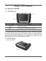
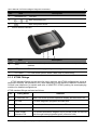
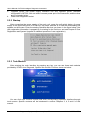
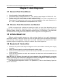
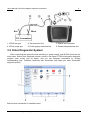
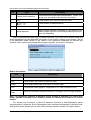
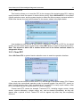
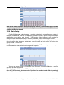
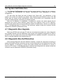
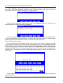
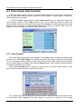
User’s Manual of KT300 Intelligent Diagnostic Instrument WELCOME TO USE KINGTEC INSTRUMENTS Thank you for using KT300 Intelligent Diagnostic Instrument (hereinafter called KT300) produced by Bosch Automotive Diagnostic Equipment (Shenzhen) Co., LTD. (hereinafter called BOSCH (Shenzhen)). This manual mainly contains more device information including use precautions; overview, registration method, connection, operation method, and upgrade method, etc. Therefore, please read this manual carefully before using the instrument so that you can use it in a quick and correct way. The manual only introduces how to operate and use the instrument. Please refer to original repair manual for repair and diagnosis of a specific automobile. The manual is prepared based on the existing functions and configurations of product. Its contents are subject to change without notice. If you still have any query after reading the manual, please contact distributors timely or directly dial the service telephone number of BOSCH (Shenzhen): 0755-83476767. Registered trademark BOSCH (Shenzhen) has registered a trademark in China and many countries with its logo as . Bosch Automotive Diagnostic Equipment (Shenzhen) Co., LTD WWW.KINGTEC.NET User’s Manual of KT300 Intelligent Diagnostic Instrument Safety Precautions Testing in good-ventilation condition, vehicle exhaust pipe should be connect to outside without enough ventilation. No smoking or fire while testing. Battery liquid of car contains vitriol that corrupts skin, so while operation you must be careful not to touch it directly especially paying more attention to your eyes. The engine works in high temperature, so you should keep away from the water tank and exhaust pipe and some other hot parts. Before starting the engine, you should pull the MT brake, particularly prevent the front wheel moving, and place the gear lever in P/N to avoid the car rushing out to hurt someone while started. If the battery is used as power supply, the red alligator clip should be connected with the battery positive and the black one with the negative. When the instrument is used in the engine chamber, all the power supply leads, the meters and the tools should be far away from the strap or other moving machines. Don’t wear watch and ring as well as large and wide clothes in the engine chamber In the process of car testing, you should wear the permissive safety glasses. Notice This unit is a hi-tech and hi-precision electronic instrument for Automotive Diagnosis, so never shake or hit while operating. Tested for the first time, the instrument may respond slowly; but wait patiently and don’t operate it frequently. The screen may blink for a moment while the engine is igniting. This is normal. If it does not run or the screen is not stable after blinking, please turn off the power supply and then try again. Make sure it is connected properly with the diagnostic connector to prevent the signal from being interrupted. Without normal connection, please pull out the connector and insert it again. Don’t shake the connector acutely while using. Try not to take down the KT600 protection cover while using it. You should try to place it on the level with the screen upwards. Try to fasten the extension leads and the connectors with snails to avoid disconnect and destroy port. When pulling out the connector, please hold firmly the front end, and don’t pull the back end of the extension leads. Try your best to carry and put it softly in safety place. Avoid colliding. If no use, please disconnect power supply. After using you should insert the touching pen in the socket in the upper-right corner of the main unit and put back fittings in the box in case of losing. Your local network influences the speed of on line upgrading. If you download at a low speed please wait patiently. The operation of the instrument needs relevant knowledge about vehicle maintenance and ECU. Bosch Automotive Diagnostic Equipment (Shenzhen) Co., LTD WWW.KINGTEC.NET User’s Manual of KT300 Intelligent Diagnostic Instrument Attention in operating an automobile ECU When you are going to operate an automobile which has installed the ECU system, you should pay more attention to the following points: Don’t put magnetic objects near ECU, such as radio loudspeakers, because the magnetic of the loudspeaker will damage the electro circuits and components in ECU. When ignition switch is turned ON, you can not turn off the automotive interior electric device, because of the self inductance effects, a very high instantaneous voltage will damage the sensors and ECU. Special attentions should be paid to avoid damaging the sensors and ECU, when repair work is near these places. As reliably as possible to connect the ECU harnesses, or it may damage the automotive interior electronic components, such as integrated circuits. When you repair the digital instrument controlled by ECU or approach the instrument,you should wear the metal strip, nip the one end to the car body and twine the other end to the wrist. Cut off the ECU system power, when welding works is going on the automobile. Unless special explains, don’t use the test lights to test the electric devices which are related to ECU in order to protect the sensors and ECU. Don’t use pointer ohmmeters to test the sensors and ECU except special explains in test program. The right type is high impedance digital instrument. Running Environment Conditions Details temperature(run-time) -10~50 ℃(14~122 °F) temperature(un-run-time) -20~70 ℃(-4~158°F) relative humidity(run-time) When 40℃,15%~95%(no frost) relative humidity(un-run-time) When 60℃, 90%(no frost) Bosch Automotive Diagnostic Equipment (Shenzhen) Co., LTD WWW.KINGTEC.NET User Manual of KT300 Intelligent Diagnostic Instrument i Contents CHAPTER 1 FOREWORD..................................................................................................................... 1 1.1 KT300 INSTRUCTION ....................................................................................................................... 1 1.2 FUNCTIONS ....................................................................................................................................... 1 1.3 FEATURES ........................................................................................................................................ 1 1.4 MAINTENANCE .................................................................................................................................. 1 1.4.1 Storage Environment ............................................................................................................. 1 1.4.2 Touch Screen Maintenance .................................................................................................. 2 1.4.3 CF Card Maintenance ........................................................................................................... 2 1.5 HOW TO GET HELP .......................................................................................................................... 2 CHAPTER 2 PRIOR TO OPERATE ..................................................................................................... 3 2.1 STRUCTURE OF KT300.................................................................................................................... 3 2.1.1 KT300 Main Unit..................................................................................................................... 3 2.1.2 KT300 Interface...................................................................................................................... 3 2.1.3 KT300 Fittings......................................................................................................................... 4 2.1.4 Specifications.......................................................................................................................... 5 2.2 KT300 USAGE ................................................................................................................................. 5 2.2.1 Power On................................................................................................................................. 5 2.2.2 Startup...................................................................................................................................... 6 2.2.3 Task Module............................................................................................................................ 6 CHAPTER 3 AUTO DIAGNOSIS .......................................................................................................... 7 3.1 GENERAL TEST CONDITIONS ........................................................................................................... 7 3.2 CHOOSE TEST CONNECTOR AND SOCKET ...................................................................................... 7 3.3 VEHICLE MODEL LIST ....................................................................................................................... 7 3.4 EQUIPMENT CONNECTION................................................................................................................ 7 3.5 ENTER DIAGNOSTIC SYSTEM ........................................................................................................... 8 3.5.1 Read Vehicle Computer Model .......................................................................................... 10 3.5.2 Read DTC ..............................................................................................................................11 3.5.3 Clean DTC..............................................................................................................................11 3.5.4 Component Control Test ..................................................................................................... 12 3.5.5 Read Dynamic Data stream ............................................................................................... 12 3.5.6 Basic Setup ........................................................................................................................... 13 3.5.7 Controller Coding ................................................................................................................. 14 3.5.8 Login ...................................................................................................................................... 14 3.5.9 Adjustment ............................................................................................................................ 15 3.5.10 Erase Self-Adaptation Value ............................................................................................ 16 CHAPTER 4 SYSTEM SETUP............................................................................................................ 17 4.1 CONTRAST ADJUSTMENT ............................................................................................................... 17 4.2 USER INFORMATION ....................................................................................................................... 17 4.3 LANGUAGE SETUP.......................................................................................................................... 18 4.4 TOUCH CALIBRATION ...................................................................................................................... 18 4.5 SYSTEM INFORMATION ................................................................................................................... 19 4.6 SYSTEM SELF-DETECTION ............................................................................................................ 20 4.7 DIAGNOSTIC BOX UPGRADE .......................................................................................................... 20 4.8 DIAGNOSTIC BOX SELF DETECTION .............................................................................................. 20 CHAPTER 5 USER REGISTRATION AND SYSTEM UPGRADE................................................. 21 Bosch Automotive Diagnostic Equipment (Shenzhen) Co., LTD WWW.KINGTEC.NET User Manual of KT300 Intelligent Diagnostic Instrument ii CHAPTER 6 AUX FUNCTION .............................................................................................................23 6.1 ENGLISH-CHINESE DICTIONARY .....................................................................................................23 6.2 RFID KEY DIAGNOSIS ....................................................................................................................23 6.3 DATA STREAM HELP FUNCTION ......................................................................................................26 6.3.1 Data Capture .........................................................................................................................26 6.3.2 Data Comparison ..................................................................................................................27 6.3.3 Value/Waveform Display......................................................................................................28 6.3.4 Data Range Reference ........................................................................................................28 6.3.5 Drive Recorder ......................................................................................................................29 CHAPTER 7 FAQ...................................................................................................................................31 ADDENDUM LIMIT RANGE OF OUR MAINTENANCE SERVICE ...............................................33 Bosch Automotive Diagnostic Equipment (Shenzhen) Co., LTD WWW.KINGTEC.NET User’s Manual of KT300 Intelligent Diagnostic Instrument 1 Chapter 1 Foreword 1.1 KT300 Instruction KT300 Intelligent Diagnostic Instrument is a diagnostic device of the latest generation of BOSCH (Shenzhen). It is a perfect product integrating electronic application technology in automobile with information and network technology, characterized by structuring, standardization, modularization and sustainable development. It contains most communication protocols of original manufacturer and communication protocol of controller local area network, with strong expansibility, and various functions can be combined freely. 1.2 Functions z z z z z z z z Automobile trouble diagnosis Data stream waveform display/storage/contrast Volkswagen/Audi repair technology manual RFID key diagnosis English-Chinese automobile dictionary Multiple upgrade methods Device self-testing function OBDII test connector compatible with model test of most 16-pin diagnostic sockets 1.3 Features z Faster running speed of system Leading 32-bit embedded chip and selected mass memory offer you a feeling of fast speed. z Higher system stability Use of advanced development methods provides fast and stable system applications, and the stability of product is improved greatly while a great amount of model information is available. z Improved system independence Applications for test of various models, stored in a storage card, are independent of one another, enabling upgrade by model. z Data stream waveform display/storage Data stream test of automobile is shown in the data stream curve, therefore, the data stream can be accurately analyzed by observing the continuous change of data stream curve. Data stream can also be stored and played back, through which any exceptions that occurs to sensors and actuator can be found. 1.4 Maintenance 1.4.1 Storage Environment z Store the instrument where it is flat and dry, with appropriate temperature and less dust, when it is not in use. Bosch Automotive Diagnostic Equipment (Shenzhen) Co., LTD WWW.KINGTEC.NET User’s Manual of KT300 Intelligent Diagnostic Instrument z z z z 2 Do not place the instrument under direct sunlight or near heater. Do not place the instrument where it is near furnace or subject to smoke erosion or water or oil spills. Do not dismantle the main unit without permission. When the main unit is dirty, please shut it down, unplug the power supply, and then use soft damp cloth to wipe the housing or screen. If test operation is not conducted for a long time, please run the main unit of KT300 regularly to avoid being affected with damp. 1.4.2 Touch Screen Maintenance z z z z z z When calibrating touch screen, do not click it before a cross cursor appears. Please use the touch pen provided in the upper right corner of the instrument to operate touch screen, and do not use nail or other sharp articles (hard object) to touch screen surface, avoiding scratch. Do not place anything on the touch screen to avoid screen distortion and damage of internal component caused as a result of heavy pressure. Do not expose the touch screen to direct sunlight or ultraviolet lamplight so as to lengthen its service life. Do not place the instrument near an electronic device which may produce electromagnetic wave interference to avoid affecting oscillograph effect. Since screen surface gathers dust due to static, it is recommended to buy special cleanser and wiping cloth for LCD to clean the screen. Do not use other chemical cleanser or clean the screen by hand. 1.4.3 CF Card Maintenance z z z Do not pull out CF card when the main unit is running. Pull it out after shutting down the main unit and attention should be paid to magnetic prevention. When conducting on-line upgrade using CF card, do not pull it out arbitrarily when card reader is running, which may cause data loss. The correct way to pull out CF card is as follows: in Windows desktop, open “My Computer” window, right-click “Movable Disk”, select “Eject” option in the pop-up menu, and then you can pull out the CF card. When the CF card of KT300 is damaged and the programs in it cannot run, you can re-make a CF card in the following steps: 1. Login on http://download.kingtec.net (KT300 download area of BOSCH (Shenzhen)) through user name and password, download KT300 upgrade tools, display program and system database to your PC by selecting corresponding product serial number. The diagnostic programs of various vehicles can be downloaded as required. 2. Install KT300 upgrades tools to your PC. 3. Format CF card of KT300. 4. Just upgrade the display program, system database and diagnostic program to your CF card by running KT300 upgrade tools. 1.5 How to Get Help KT300 provides users with powerful random help and on-line help functions. In the actual test, there is a ? Help button on the interface to provide help information of the current screen for operation. If you would like to know the latest products of BOSCH (Shenzhen) or diagnostic information of other automobiles, you can get complete detailed help by visiting our website http://www.kingtec.net/ through Internet. Bosch Automotive Diagnostic Equipment (Shenzhen) Co., LTD WWW.KINGTEC.NET User’s Manual of KT300 Intelligent Diagnostic Instrument 3 Chapter 2 Prior to Operate 2.1 Structure of KT300 2.1.1 KT300 Main Unit No. Item Description 1 Power supply indicator Power supply indicator on when the main unit of KT300 is powered on and started 2 Screen TFT640 x 480 5.6 inch touch screen, true color 3 Touch pen To operate screen The above figure shows introduction to the main unit of KT300, inside which two modules are included: KT300ARM main board and KT300IO board. These two modules, integrated as one unit, play diagnosis function in repair work. In addition, KT300 is also equipped with some Fittings required for automobile diagnosis and on-line upgrade, such as test extension line, power supply extension line, automobile alligator clip, cigarette igniter connector, 14V power supply, CF card, CF card reader and various test connectors, etc. 2.1.2 KT300 Interface z View of top interface Bosch Automotive Diagnostic Equipment (Shenzhen) Co., LTD WWW.KINGTEC.NET User’s Manual of KT300 Intelligent Diagnostic Instrument No. 1 Item 4 Description DIAGNOSTIC Test port 2 Main unit power port 3 Main unit power switch View of bottom interface z No. Item Description 1 SP/2 To connect with keyboard and mouse, or used as serial port through switcher 2 NET To achieve online upgrade by connecting to network cable 3 CF CARD CF card socket (shown when rubber strip is pulled away) 2.1.3 KT300 Fittings KT300 standard fittings are the same for every machine, but KT300 configurations (such as diagnostic software, test connector, etc.) differ depending on the demand of different customers. Consult local distributor for details and refer to KINGTEC KT300 packing list accompanying machine for detailed configurations. KT300 standard fittings are listed as follows: No. Fitting Name Remarks 1 KT300 main unit Main unit screen provides operation display and test result, etc. 3 CF card To store diagnostic programs and data files 4 CF card reader To read data from and store data into CF card 5 Test extension line To connect test connector and test interface on the main unit 6 Power supply extension line To connect automobile alligator clip to provide power for the main unit through battery/cigarette igniter (extension role) Bosch Automotive Diagnostic Equipment (Shenzhen) Co., LTD WWW.KINGTEC.NET User’s Manual of KT300 Intelligent Diagnostic Instrument 5 7 14V power supply To convert 100-230V AC power supply into 14V DC power supply 8 Automobile alligator clip To get power from automobile battery 9 Cigarette igniter To get power from cigarette igniter 10 Touch pen To operate interface buttons of KT300 by clicking 11 Test connector Used to connect automotive diagnostic socket and KT300 for automobile diagnosis 2.1.4 Specifications Main unit Item Index Voltage of power supply 11–14V DC Operating temperature -10℃–50℃ Relative humidity < 90% RJ45 network interface 10 M SP/2 interface Standard SP/2 interface CF card interface For plug and play of CF card Hardware configuration System hardware Index CPU 32-bit embedded chip Main frequency 80 MHz Flash memory Very large capacity FLASH, re-writable External memory CF card, expandable discretionally Display 5.6 inch LCD touch screen, true color 2.2 KT300 Usage 2.2.1 Power On There are four methods to provide power for the KT300 main unit, from which you can select as needed: 1. 2. AC power: use power adapter, standard configuration of KT300, with one end to connect power port of the instrument, and the other end to AC outlet. Automobile battery: use power supply extension line and automobile alligator clip, standard configuration of KT300, with one end to connect power port of the instrument, and the other end to automobile battery. Bosch Automotive Diagnostic Equipment (Shenzhen) Co., LTD WWW.KINGTEC.NET User’s Manual of KT300 Intelligent Diagnostic Instrument 3. 4. 6 Cigarette igniter: use power supply extension line and cigarette igniter, standard configuration of KT300, with one end to connect power port of the instrument, and the other end to cigarette igniter. Power from diagnostic socket. 2.2.2 Startup After connecting the power supply of the main unit, press the soft switch button of power supply at the upper left corner of KT300 top, the power indicator is on and the downloading bar appears on the screen. Enter the starting interface after that, as shown in the figure below: (the user registration information is popped up for starting for the first time, and see Chapter 5 User Registration and System Upgrade for detailed operation of user registration). 2.2.3 Task Module After entering the main interface by pressing any key, you can see three task modules provided by KT300: Auto Diagnosis, System Set and Aux Function, shown as below: You can click each function module and enter corresponding operation interface through touch screen. Specific contents will be introduced in section Chapters 3, 4, 5 and 6 of this manual. Bosch Automotive Diagnostic Equipment (Shenzhen) Co., LTD WWW.KINGTEC.NET User’s Manual of KT300 Intelligent Diagnostic Instrument 7 Chapter 3 Auto Diagnosis 3.1 General Test Conditions z z z z Open the switch of automobile power supply. Automobile battery voltage should be 11~14V, and the rated voltage of KT300 is DC 12V. Throttle should be in closed state, namely closed at idle joint. Ignition timing and idle should be within standard range, and water temperature and transmission oil temperature reach normal working temperature (the water temperature is 90~110oC, and the transmission oil temperature is 50~80oC). 3.2 Choose Test Connector and Socket KT300 is equipped with multiple test connectors, which you can select depending on the specific type of automobile diagnostic socket. The position of diagnostic socket varies with different models, please use correct diagnostic socket for test. (For selection of test connector and determination of diagnostic socket position, refer to Appendix II and Appendix III) 3.3 Vehicle Model List Different vehicle models emerge one after another thanks to the rapid development automobile industry. KT300 can provide you with the latest and most accurate test information timely through on-line upgrade. Please get new model information and download the latest upgrade program of diagnosis by visiting our website: http://www.kingtec.net. 3.4 Equipment Connection 1. 2. 3. 4. Determine the position and shape of diagnostic socket, and whether external power supply is needed. Select connector based on model and diagnostic socket shape. Insert one end of test extension line into the test port of KT300, and connect the other end to test connector. Insert the test connector to which test extension line has been well connected into the diagnostic socket. Note: Be sure to connect the main unit, test extension line and diagnostic connector before connecting test connector to diagnostic socket, or diagnostic socket fuse may be melted down due to short circuit of wire during connection. If the automobile diagnostic socket is not powered on, refer to the following figure for specific connection: Bosch Automotive Diagnostic Equipment (Shenzhen) Co., LTD WWW.KINGTEC.NET User’s Manual of KT300 Intelligent Diagnostic Instrument 8 1: KT300 test port 2: Test extension line 3: Special test connector 4: KT300 power port 5: Power supply extension line 6: Double clamped power line 3.5 Enter Diagnostic System After connecting the instrument and switching on power supply, start KT300 and enter the main menu. Select Auto Diagnosis module, shown in the figure. KT300 automobile diagnostic program uses model logo as button, and you can diagnose automobile by clicking corresponding logo. Therefore, familiarity with automobile logo helps you enter automobile diagnosis quickly. Brief function introduction to interface menu: Bosch Automotive Diagnostic Equipment (Shenzhen) Co., LTD WWW.KINGTEC.NET User’s Manual of KT300 Intelligent Diagnostic Instrument No. Item 9 Description 1 Vehicle series selection China/America/Europe/Japan/Korea/OBDII, select the proper one according to the vehicle to be tested 2 ESC Touch button, exit, return to previous menu 3 Touch button, to select direction 4 OK Touch button, to confirm 5 Model selection Make proper selection according to the model to be tested (model logo will be sorted automatically based on your use frequency) Select corresponding model logo for vehicle fault test. If you click China vehicle series and Audi/Volkswagen logo, the diagnostic information of the vehicle is shown on the screen. V02.06 is the diagnostic model version of the model in the instrument (depending on different test versions, such number may change after program upgrade), as shown in the figure: Button description: Item Description OK Touch button, to confirm selection, execute current task ESC Touch button, exit, return to previous menu ? Help To provide relevant help information of current page Print To save the current page to Temp folder in CF card in the form of file Page Up/Page Down When all information cannot be shown in one page, use it to page up/down Note: The diagnostic interface of different vehicle models is operated in a similar way. Please operate according to the interface prompt for detailed test methods of various models. The manual only introduces in detail all detection functions of Audi/Volkswagen series engine system for reference. Since Volkswagen series vehicles are diagnosed in the same way, directly click Select System item to enter next operation interface, shown in the figure below: Bosch Automotive Diagnostic Equipment (Shenzhen) Co., LTD WWW.KINGTEC.NET User’s Manual of KT300 Intelligent Diagnostic Instrument 10 KT300 can diagnose all current Audi/Volkswagen models in China, Skoda series, SEAT series, and small red flag models equipped with waveform electronic control system as well as some mini vehicle. It can test 87 electronic control systems from original manufacturers. Test functions includes reading DTC, cleaning DTC, reading data stream, basic setup, controller coding, unit control test, various adjustments and matching, self-adaptation clearing, system login and matching anti-theft key, etc. Note: Different systems are tested in a similar way, and we will take engine system as an example for description. Select 01-Engine, and automobile computer version number appears. Since some models may have several screen displays, please click to view. After reading automobile computer version number, press any key to enter system diagnosis interface. We will describe function menus of each test system in the following. 3.5.1 Read Vehicle Computer Model The function allows you to read computer information of tested system, including version number, coding number, service station code and relevant information. Generally, when replacing vehicle control unit, you need to read original control unit information and record it as a reference for buying new control unit. When coding new control unit, original control unit information is needed. After you select 01-Read Vehicle Computer Model in the system function selection menu, the screen displays as following: Since some models may have several screen displays, please press any key or click screen to display next screen. Press ESC to return to previous one. Bosch Automotive Diagnostic Equipment (Shenzhen) Co., LTD WWW.KINGTEC.NET User’s Manual of KT300 Intelligent Diagnostic Instrument 11 3.5.2 Read DTC This function allows you to read the DTC in the storage of the tested system ECU, helping repair personnel check the reason of vehicle failure quickly. Select 02-Read DTC in the system function selection menu, and the system begins to detect the failure memory contents stored in ROM. After the test, the result will be shown on the screen, shown in the figure below: Use scrollbar to scroll screen to view all DTC information. If there is no DTC for the tested system, no DTC will be shown on the screen. Select ESC button to return to the previous menu. Note: The failure for which /SP is marked at the end of the failure contents shown is abiogenetic failure. 3.5.3 Clean DTC Select 05-Clean DTC in system function selection menu to enter the operation interface: You can use this function to clean the DTC in the storage of the tested system ECU. Please follow strictly the conventional operation order for general models: first read DTC, record (or print) it before cleaning them, then conduct trial run, re-read DTC to verify, repair vehicle, clean DTC, re-conduct trial run to confirm that DTC does not appear. Current hard DTC cannot be cleaned. Technical DTC, including oxygen sensor, knock sensor, mixture calibration, cylinder misfire, etc., can be cleaned immediately, but they will appear after a period of time. These DTC will not appear only after they are completely removed. Bosch Automotive Diagnostic Equipment (Shenzhen) Co., LTD WWW.KINGTEC.NET User’s Manual of KT300 Intelligent Diagnostic Instrument 12 3.5.4 Component Control Test This function allows you to check the circuit working conditions of actuator, and observe whether this actuator works normally when you conduct the control test. If the actuator does not work normally, you need to check whether there is a failure in relevant electronic components, plug harness or mechanical parts. Select 03-Component Control Test in system function selection menu to enter operation interface, shown in the figure below: The instrument panel system will simulate display, and you can observe instrument for failure. Press any key or click screen to enter the component test. In this case, all warning indicators on the instrument panel are shown, from which you can judge instrument warning indicators or circuit for failure. Click Continue button to enter test of next component and operate it in the same way above until all components of the tested system are tested. Press ESC key to return to the system function selection menu. Note: Refer to the original manual for use of 03-Component Control Test function, avoiding causing vehicle failure. 3.5.5 Read Dynamic Data stream Audi/Volkswagen vehicle series have complete data stream but original manual is needed, or you can only show data without knowing exact contents. Select 08-Read Dynamic Data stream in the system function selection menu to enter the operation interface. For example, after you enter the test system for Audi/Volkswagen vehicles, the instrument reads data streams of groups 1, 2 and 3 by default. You can increase or reduce the group number by clicking group adjustment box order on the screen interface, and then select different data streams. You can also directly click the group number box and input specific group number of data stream using pop-up small keyboard, as shown in the figure below. Using this function, you can read the dynamic data stream of any group. Bosch Automotive Diagnostic Equipment (Shenzhen) Co., LTD WWW.KINGTEC.NET User’s Manual of KT300 Intelligent Diagnostic Instrument 13 How to use small keyboard: Input specific group number in the selected group number box through Arabic numbers in the small keyboard, use Del key to delete, Enter key to confirm and Esc key to exit. 3.5.6 Basic Setup For Audi/Volkswagen vehicle series, it needs to make basic setup after some system is repaired or maintained, such as self-adaptation process of throttle, ignition timing, mixture, idle stabilization valve setting, and exhaust of ABS system. Select different group number for different models and the basic setup of different parameter, subject to the original manual. Generally, you can view the data stream corresponding to basic setup group number. If there is no such data stream or data stream does not match the basic setup, the basic setup group number is not correct. The operation steps for basic setup are as follows: select 04-Basic setup function in system function selection menu, with the following screen displays: You can set group number using pop-up small keyboard, and select Ok button to confirm and then exit after completion. Note: Setting conditions are: no DTC stored in control unit; coolant temperature not less than 80oC; all electronic device turned off (radiator fan must be turned off during setting), air conditioner turned off. Bosch Automotive Diagnostic Equipment (Shenzhen) Co., LTD WWW.KINGTEC.NET User’s Manual of KT300 Intelligent Diagnostic Instrument 14 3.5.7 Controller Coding If the vehicle code is not shown or the main computer has been replaced, it needs to conduct control unit coding. If the new control unit has the same part number and index number as that of the old one, you just need to read the coding of the old one and then code them into the new one. Generally speaking, if the vehicle configuration is different, it is certain that control unit coding is different. The control unit of some vehicle models allows coding one time, and wrong coding may cause poor performance of vehicle, and as a worse result, cause serious failure to vehicle, therefore, try to avoid misoperations. Select 07-Controller Coding in system function selection menu, and the system pops up a window to input coding value, as shown in the figure below: After clicking the input window, input correct control unit coding in the new CODING box using pop-up big keyboard (see 4.2 User Information section for key description of big keyboard). Click Enter key to confirm and exit or click Conform key to complete coding after directly clicking ESC to exit big keyboard. Return to the previous level to re-execute 01-Read Vehicle Computer Model function, and you can view if the coding you have just input is shown behind CODING. 3.5.8 Login You need to log in before executing 10-Adjust function in system. For example, matching anti-theft key, adjusting some group numbers of instrument system, idle adjusting of some vehicle models require login before each function can be executed. Select 11-Login function in system function selection menu, and press OK key, with screen display as the figure below. After inputting login password using small keyboard, click Enter key to confirm and exit, or directly select ESC key on the small keyboard to exit. Click Ok button in the interface prompt menu to log on. Press ESC button to return to the previous menu. Bosch Automotive Diagnostic Equipment (Shenzhen) Co., LTD WWW.KINGTEC.NET User’s Manual of KT300 Intelligent Diagnostic Instrument 15 3.5.9 Adjustment The adjustment function is used in different way for group number of each system, and you need to view the original manual of the vehicle model before operation. Not all models have such function; it is key whether the control unit of vehicle model supports such adjustment function. Using this function, you can achieve anti-theft key matching, idle stabilization valve setting, etc. First, select 11-Login function in system function selection menu. After successful login, select 10-Adjust function to enter the following operation interface: When using adjustment function, by referring to the original manual, first input group number you want to adjust using pop-up small keyboard, and click Read button. The system will read the Original Value of the group number. Input desired value by selecting Adjust Value field, using pop-up big keyboard (see 4.2 User Information section for key description of big keyboard). Click Test button to enter the testing. After the test, click Save button, and the system will save the adjustment information. Press ESC key to exit the adjustment function. Note: z z When matching anti-theft key, the matching time for each key should not exceed 30s. Do not insert the key you have just matched into ignition switch for re-matching, otherwise anti-theft key matching automatically terminates, and re-execution of such function is needed. The key without chip cannot be matched. Bosch Automotive Diagnostic Equipment (Shenzhen) Co., LTD WWW.KINGTEC.NET User’s Manual of KT300 Intelligent Diagnostic Instrument 16 3.5.10 Erase Self-Adaptation Value The function of erasing self-adaptation value, equivalent to 00 group of the adjustment function, is for purpose of restoring initial value of control unit. When replacing the engine computer on Audi/Volkswagen vehicle model where the second generation of anti-theft computer is installed, you just need to enter anti-theft system and select the erasing self-adaptation value function in the system function selection menu without the need to match key. Select self-adaptation erasing and then press OK key, and “Do you want to execute this operation?” will be shown on the screen. Press Confirm key to execute it, and the system will prompt you that “Self-adaptation value has been erased”. After that, press ESC key or click screen anywhere to exit. When an illegal key is used to start engine, anti-theft will be triggered. In this case, you just need to insert a legal key into ignition switch and open it without starting engine, and use self-adaptation erasing function to release anti-theft without the need to match key. Note: If the Engine is locked, you have no choice but to insert the legal key into ignition switch and wait until locking ends, and then you can start engine. Bosch Automotive Diagnostic Equipment (Shenzhen) Co., LTD WWW.KINGTEC.NET User’s Manual of KT300 Intelligent Diagnostic Instrument 17 Chapter 4 System Setup 4.1 Contrast Adjustment This function menu allows you to adjust the contrast of LCD display. Because of its property, LCD can have different display effect in an environment of different contrast, temperature and humidity. You can adjust at any time the contrast of LCD to achieve the optimal display effect. By clicking direction touch button under the screen menu, you can increase and decrease contrast percentage. After adjustment, press ESC button to exit and save adjustment result. 4.2 User Information By clicking the User Information module, you can enter user information input window where you can input your own relevant information to meet the need of automatic retrieval of service code by the system during automobile diagnosis. Detailed operation steps are as follows: 1. 2. 3. Click Amend button next to the service code, and input service code information through pop-up big keyboard. Select ESC button to exit. Enter service name input window, click Amend button next to the service name and then input service name information through pop-up big keyboard. Input user’s name in the same way as above, press Save button to save your user information after confirmation. The interface is shown in the following figure: Bosch Automotive Diagnostic Equipment (Shenzhen) Co., LTD WWW.KINGTEC.NET User’s Manual of KT300 Intelligent Diagnostic Instrument 18 Key description of big keyboard ESC To exit current interface and return to previous one En/Cn Chinese/English switch button Shift Upper/lower cases switch, input of special characters. Click this button to input upper case letters or special characters. Del To delete the character in front of cursor Enter To confirm or exit Inputting window cursor move key and direction key allow Chinese character selection at Chinese character input status ∨ ∧ Up/down movement switch button 4.3 Language Setup KT300 provides two kinds of languages, that is, simplified Chinese and English for your selection. z z z Step 1: Enter Language Setup module. Step 2: Select desired system language. Step 3: Select OK button to confirm the selection of system language, and the new system language will be shown. 4.4 Touch Calibration If you feel there is distortion in touch screen when using it, you need to calibrate the touch screen. Click Touch Calibration module to enter the touch calibration window, as shown in the figure below: Bosch Automotive Diagnostic Equipment (Shenzhen) Co., LTD WWW.KINGTEC.NET User’s Manual of KT300 Intelligent Diagnostic Instrument 19 Depending on the prompt, use touch pen to click the center of cross cursor accurately, and one time of calibration is completed after change occurs. After that, the cursor moves to other corners of the screen. After you complete the calibration for each corner, the system will prompt whether touch screen is calibrated successfully. The system will automatically return to system setup menu. Note: Do not click screen arbitrarily before cursor appears, which may cause calibration failure! 4.5 System Information You can query detailed information of system through system information module: After entering main interface of system setup, click System Information module, and the main menu will list the serial number, register password, register?, product name, instrument model, dealer code, distribution code, manufacture company, product date, diagnosis software version and diagnosis hardware version of the system in the machine, as shown in the figure below: Bosch Automotive Diagnostic Equipment (Shenzhen) Co., LTD WWW.KINGTEC.NET User’s Manual of KT300 Intelligent Diagnostic Instrument 20 4.6 System Self-Detection Click System Self-Detection module and the system begins to detect its own hardware. The system will automatically list relevant Self-detection items depending on current configuration. You can select the items you want to detect (note: items with * are mandatory), or the system will conduct full detection by default. After determining self-detection items, click Ok button and the system enters self-detection status during which your coordination may be required. Please operate it according to interface prompt. After the full detection is completed, if everything is normal, the screen shows that all detections are normal (some detection items need your judgment, such as LCD detection; therefore the system does not provide detection results for these items). If there is an abnormal item, it indicates that there is a failure in the instrument, please contact the customer service department of BOSCH (Shenzhen) timely. 4.7 Diagnostic Box Upgrade Make sure KT300 main unit and CF card are connected and powered on, enter diagnostic box upgrade interface, and click OK button, the program will upgrade the diagnostic box. After a period of time, the system will prompt that “Diagnostic box upgrade successful”, and press any key to complete diagnostic box upgrade and exit. 4.8 Diagnostic Box Self Detection After entering diagnostic box self detection interface, connect the instrument according to system information prompt, and press any key to enter diagnostic box self detection mode. After the self detection, if everything is normal, the screen prompts that the detection is normal. If there is a DTC shown, it indicates that there is a failure in the diagnostic box, please contact the customer service department of BOSCH (Shenzhen) timely. Bosch Automotive Diagnostic Equipment (Shenzhen) Co., LTD WWW.KINGTEC.NET User’s Manual of KT300 Intelligent Diagnostic Instrument 21 Chapter 5 User Registration and System Upgrade On-line upgrade function of KT300 allows you to easily download software of the latest version for upgrade through Internet. BOSCH (Shenzhen) provides software of the latest version at download area at http://download.kingtec.net:86/down/e/?u=3, and also prompt information at upgrade notice column. You can visit it through Internet, and download KT300 software of the latest version after registration. Downloaded software saves the diagnostic program to CF card using upgrade tool, and then you can upgrade the KT300. In this chapter, we introduce in detail the whole process of KT300 registration and upgrade, and please read it carefully when you conduct the registration and upgrade. Specific steps for user registration are as follows: Preparation before upgrade: a computer that can access the Internet; USB port works normally; KT300 main unit, special CF card and card reader. z Step 1: Check the product serial No.. Start the KT300 intelligent diagnostic instrument, select System Set module after entering main interface, and click System Information button to enter system information interface where you can find serial number and registration password of this machine. z z Step 2: Into the registration interface. Log in BOSCH (Shenzhen) website http://download.kingtec.net:86/down/e/, and click Register Now to enter user registration wizard interface. And then register according to registration wizard. Select Registration Password is I have found registration password and click Next button to enter next operation. Input your serial number、registration password and verify code in prompt box on the interface, and press Submit key to verify. Step 3: Fill in the personal information. After submitting the product information, enter the interface for filling in personal information where you are required to fill in your personal information carefully, and then submit it. Note: User name is used to log in for future upgrade and cannot be duplicated, so it is recommended to use real name for registration. E-mail is used to get back password, and fill in your E-mail you usually use. Please keep in mind your user name and password before submitting your personal information. z Step 4: Registration succeeds (after correct personal information is submitted, the system prompts Successful Registration) Specific steps for software upgrade are as follows: z z z Step 1: Log in BOSCH (Shenzhen) website http://download.kingtec.net, and in registered user login (KT300) field select your registered user name or product serial No. to log in. After login, you can download automobile diagnosis upgrade program relating to KT300 and save them to your computer (it is recommended to create a new folder named “KT300 upgrade” to save downloaded files). Step 2: Connect CF card to your computer using card reader, run the upgrade program you have just downloaded (upgrade program files of complete packs are large, and it may take a little long time during which you cannot re-click to run upgrade program). Step 3: Insert CF card into CF card socket of KT300, start machine and run diagnostic kit upgrade according to system interface prompt to complete upgrade. Bosch Automotive Diagnostic Equipment (Shenzhen) Co., LTD WWW.KINGTEC.NET User’s Manual of KT300 Intelligent Diagnostic Instrument 22 Upgrade precautions: z z z z KT300 upgrade is to update the data in CF card, so it is required to select correct CF card to ensure normal card reader. Make sure complete upgrade process, and do not pull out CF card or force to terminate program, which may cause damage to CF card. After upgrade, insert CF card into KT300 main unit to check whether it is normal. If not, contact us timely. When running KT300 for the first time, please download “Complete upgrade packs of KT300”, and format CF card before running upgrade program. Note: If you have any query about KT300 user registration and system upgrade, please refer to on-line registration; upgrade files and demonstration video of our company. Bosch Automotive Diagnostic Equipment (Shenzhen) Co., LTD WWW.KINGTEC.NET User’s Manual of KT300 Intelligent Diagnostic Instrument 23 Chapter 6 Aux Function 6.1 English-Chinese Dictionary The English-Chinese dictionary of automobile gives explanations to specialized terms of automobile, with which the system will give corresponding information if you input relevant terms. Detailed operation steps are as follows: After entering the Aux Function module, select Dictionary on the main interface to enter the following interface. Click the big keyboard icon at the upper right corner of the screen to pop up big keyboard as shown (see 4.2 User Information section for key description of big keyboard). Input the information (in English) you want to query using big keyboard, and click Search button, all matching information (as shown in the figure below) will be shown if the system finds results. Click the direction selection button under the screen menu to determine the item you query. No content is shown in the information list box if the system cannot find matching information. 6.2 RFID Key Diagnosis RFID key diagnosis is an optional function specially provided in KT300, therefore automobile key detection box is not a standard kit. So you can order it from our company separately as needed. This section will introduce in detail the specific operation of function of RFID key diagnosis function. RFID key diagnosis function works with automobile key detection box of our company which can read/write the types and key IDs of full series of key chips, and can also read EEP ROM in automobile system closely related to key. Key diagnosis box can be used with PC’s associated software through USB port. The specific operation methods of RFID key diagnosis function are as follows: Step 1: Detect the key. Bosch Automotive Diagnostic Equipment (Shenzhen) Co., LTD WWW.KINGTEC.NET User’s Manual of KT300 Intelligent Diagnostic Instrument 24 After connecting KT300 and key diagnosis box, insert automobile key into the socket of key box, select RFID key diagnosis under the Aux Function module, and click to enter the key/storage detection interface, as shown in the figure below: Wait while the systems is detecting key after clicking Detect Key button, and enter the following operation interface if the key is detected: If there is no key in the socket of the key box, the interface will prompt “No key detected”. If no key is detected due to communication, the system will take a short time to conduct multiple detections, and then the interface prompts “Communication abnormal error”. Step 2: Read/write the storage. Before reading/writing the storage, please pull up chip bar and install IC properly according to the direction marked on the key box (semi-circle opening or small round opening and other marks should be consistent in direction with that marked on the key box, with the socket at the mark as starting point). And then pull down chip bar. Click Select Chip button to select the type corresponding with IC (note: if improper type is selected, no IC information can be read/written. If there is no IC information you want to read/write, please contact us timely), as shown in the figure below: Taking 24C08 chip as an example, select 24C08 and then click Next button to enter next operation interface: Bosch Automotive Diagnostic Equipment (Shenzhen) Co., LTD WWW.KINGTEC.NET User’s Manual of KT300 Intelligent Diagnostic Instrument 25 After the selected IC is detected, click Read Storage button to read IC information. During reading, the communication indicator (green) near the power supply indicator flashes, the system enters the following interface after reading: On the interface, you can use scroll button to browse all IC information that have been read, and save them to CF/OSCSAVE/24C08-XX.txt (XX is a number between 0-39). You can modify the data related to IC according to key information using PC, and then call the modified information (the software will automatically monitor the text information that has been saved previously). Select the group number folder in which you want to save after modification, and then confirm to enter the following interface: After you select Confirm to Write IC button, the system enters a status of writing IC. During the sending of information, the communication indicator (green) near the power supply indicator flashes. After the sending of information, key diagnosis operation is completed. Bosch Automotive Diagnostic Equipment (Shenzhen) Co., LTD WWW.KINGTEC.NET User’s Manual of KT300 Intelligent Diagnostic Instrument 26 6.3 Data stream Help Function KT300 provides powerful function of random data stream help. Now we will introduce in detail the data stream help function by taking TOYOTA CAMRY engine system of Japanese vehicle series as an example. In TOYOTA CAMRY engine system, select Data List test menu to enter data stream test result display interface. Click? Help button to pop up the following window in which the communication data, picture browse, data stream file management, data range reference, data capture, data comparison, and data stream-related setup menu are shown. After a menu is selected, a red “V” appears on the right side of this menu. 6.3.1 Data Capture After entering the data stream test interface, click? Help button to enter data stream help function menu. After Data Capture is selected, the system will record all data currently tested. You can use page up/down function to make the device record all data, otherwise only the data on the current page is recorded. After clicking Record button, enter interface saving function. The specific operation is as follows: After clicking Record button, a dialog box requiring you to input file name pops up if the device allows to input saved files, shown in the figure: The interface pops up a dialog box to input file name, and at the same time shows the file that has been saved regarding this data stream, to prevent the original file from being Bosch Automotive Diagnostic Equipment (Shenzhen) Co., LTD WWW.KINGTEC.NET User’s Manual of KT300 Intelligent Diagnostic Instrument 27 overwritten by a file with the same name input by user. If the file name you input exists, the system determines that the user will overwrite the original file by default, and will not give any prompt. File name is shown as: file name input by user + suffix of one character. If a file name input by user is E800, and it will be shown as E8001. Please input correct file name and then press Ok button, the system will automatically save it to NOTE folder in CF card. If you press Record button and the recorded files about the data stream has reached three, the system prompts the following dialog box requiring you to delete these files. The files saved for each data stream can be three as a maximum. In this case, select the file name you want to delete, and then click Delete button to delete it. 6.3.2 Data Comparison After saving file, press? Help button and select Data Comparison in the help menu, the system can call the data files that have been saved for data comparison, as shown in the figure below: The figure above lists all files about the data stream and you can select corresponding data stream as needed and select display methods: single frame comparison and automatic judgment. The following interface is shown after single frame comparison is selected, and you can judge whether the input is correct through this interface: The following interface is shown after the selection of automatic judgment: Bosch Automotive Diagnostic Equipment (Shenzhen) Co., LTD WWW.KINGTEC.NET User’s Manual of KT300 Intelligent Diagnostic Instrument 28 Comparison range values shown on this interface are: reference value multiplying a deviation. The deviation can be set through data stream result deviation setup item in Data stream-related Setup function in the data stream help function menu. 6.3.3 Value/Waveform Display After entering the data stream test interface, select Value/Waveform Display in? Help function menu, and the system pops up Value/Waveform display dialog, with which the change trend of a data stream group value is shown clearly, helping you judge the failure of automotive electronic device quickly. You can select different data stream groups for waveform display through inverted triangle on the interface. 6.3.4 Data Range Reference In data stream help function menu, select data stream range reference to enter data stream reference function page. The middle part of this page is reference data which you can record and save in the system after capture. The system automatically compares tested data with the range, if the tested value is not within the range, the value will be considered incorrect and shown in red font for check. In this case, the device records data at the same time. If you press Record button, the device will use the current value tested to modify the current data range. Bosch Automotive Diagnostic Equipment (Shenzhen) Co., LTD WWW.KINGTEC.NET User’s Manual of KT300 Intelligent Diagnostic Instrument 29 6.3.5 Drive Recorder Driver Recorder is mainly used to long time record some data in ECU. It can record 6 different data in maximum at the same time and the record time for every data is about one hour (it will vary according to the communication rate between diagnostic device and ECU). During the recording process, data can be recorded at any time into temp folder of CF card as the xx.osc format. The temp folder will be created by system automatically. When enter automotive diagnosis function, user can playback the waveform by “Driver Record Playback” function in the help menu. Detail usages are as follows: 1、 Driver Record When reading some data stream in ECU, user can record the driver record by “Driver Recorder” function in the help menu and select “Driver Recorder” to enter the following window: This window will record the first six data in default. User can select different data options by the triangle down button on the left. The recorded data stream window will display its data stream name, current value and unit, and also the speed. It will be completed when the progress bar occupies the whole record bar. F:1/ at the lower left window is sampling rate. The sampling rate is decided by the communication rate between diagnosis device and ECU, for example: when an ECU is reading data stream, it can communicate with diagnosis device at rate 8, at the same time F:1/ is set to 2, so it can record 4 data per second. ESC ------ Exit waveform recording OSC ------ Perform real-time monitoring of waveform SAVE ------ Save the waveform data into the temp folder of CF card as the xx.osc file format. The filename has 8 characters in maximum and 32 files recorded at most. 2、Waveform real-time monitoring Select “OSC” at the above figure to enter waveform real-time monitoring window, as the figure below shows: Bosch Automotive Diagnostic Equipment (Shenzhen) Co., LTD WWW.KINGTEC.NET User’s Manual of KT300 Intelligent Diagnostic Instrument 30 The window displays the data by waveform. User can view waveform at any time slot by the slider bar in the window. It can display at most 6 waveforms. When viewing the waveforms, the system is still recording the data, but the window doesn’t refresh automatically. Left side of the above figure is the data stream name and Max/Min value. User can not modify the recorded data streams, but can save them. When exit the Driver Recorder, user can playback the waveform by “Driver Record Playback” function in the help menu. Select the file you want to playback and enter the window like waveform real-time monitoring window to playback the waveform. Bosch Automotive Diagnostic Equipment (Shenzhen) Co., LTD WWW.KINGTEC.NET User’s Manual of KT300 Intelligent Diagnostic Instrument 31 Chapter 7 FAQ 1. When the instrument is used to repair vehicle, you cannot enter the system. Answer: The common reasons include: Wrong power supply of the control unit, including problems on positive and negative, etc. z Wrong connection between the control unit and diagnostic socket. z Damaged control unit. z Outdated version of decoder software. z No self-diagnosis function available for the system. What if the prompt of “Communication with automobile computer error” appears when the DTC is read? z 2. Answer: The possible reasons include: Detection connector is badly connected. Please check whether the detection connector is properly connected with automobile diagnostic socket. z Connection trouble of automobile self-diagnostic socket, please use a multimeter to test whether each terminal meets normal conditions. z Fluctuated power supply of decoder, for example, run decoder test while starting vehicle. Why can part system of some vehicle be tested while other system cannot be entered? z 3. Answer: This is caused by the abnormal diagnostic line of some systems. The decoder requires two-way communication between signal line of diagnostic socket and corresponding vehicle computer to complete failure reading, failure clearing, data stream reading and terminal element controlling. Please use a multimeter to test whether each terminal of diagnostic socket meets normal working conditions (for example, ignition power supply, grounding line, communication line and system control unit, etc. should be in normal condition). 4. When testing automobile, you can enter the system for testing, but the communication is often interrupted. Answer: This is caused by the interference. Keep the test extension line away from strong interference sources. In addition, it is advisable to use automobile battery as power supply for the decoder, so that the external decoder has favorable grounding with automobile electronic system, providing strong anti-interference ability. 5. When the automobile is tested, the communication speed is very slow, but works. Answer: The speed of device and automobile communication depends on the performance of automobile computer. A decoder is used to detect a PCM with low baud rate in a lower speed than when it is used to detect a PCM with high baud rate. For example, GE Company adopted early low speed PCM of 160 baud rate as its control system, but now the control system of new GE vehicle adopts 8192 baud rate, it is certain that there is a large difference in communication speed. 6. Touch screen responses slowly in cold weather. Answer: Slow response of touch screen is caused by over low temperature because each element has its own temperature range (the working temperature range of this machine is -10℃–50℃). In the case of low environmental temperature, please preheat it for 30 minutes after it is powered on. 7. Communication with ECU fails. Bosch Automotive Diagnostic Equipment (Shenzhen) Co., LTD WWW.KINGTEC.NET User’s Manual of KT300 Intelligent Diagnostic Instrument 32 Answer: Check whether the test connector and test program match vehicle model. 8. When the system is started, it prompts that no CF card is found or it cannot enter the diagnostic interface: Answer: This often happens when the CF card is not inserted, inserted improperly or damaged. Bosch Automotive Diagnostic Equipment (Shenzhen) Co., LTD WWW.KINGTEC.NET User’s Manual of KT300 Intelligent Diagnostic Instrument 33 Addendum Limit range of our maintenance service Basic information Problem caused by the quality of the machine in correct use can be partially solved by BOSCH (Shenzhen) Company during the guarantee time. When there is problem on our instrument, contact the distributor directly. BOSCH (Shenzhen) Company has after sales engineers in each big and middle city in our country through strictly select and excellent training, which will offer high efficiency and good quality service. Guarantee time refers to the period BOSCH (Shenzhen) Company sells the product. Detailed guarantee information consult system record of BOSCH (Shenzhen) Company. Users keep the guarantee card and purchasing voucher distributor open when sell instrument carefully. When the instruments need to be repaired, the vouchers mentioned above are regarded as guarantee proof. Register the instrument in time. Guarantee time start from the register date system record. Repaired instrument still enjoy maintenance service in warranty time. If warranty time will be end in three months, replaced spare parts enjoy three-month maintenance since replace. Spare parts replaced in maintenance period belong to BOSCH (Shenzhen) Company. Users should take responsibility for the safety of data. Before maintenance, users backup the data and program automatically. BOSCH (Shenzhen) Company and our distributors don’t take any responsibility for destruction or loss of data, program or memory medium. Out of guarantee range as follows Technology problem of non-hardware (visit BOSCH (Shenzhen) Company’s website http://www,kingtec.net or call after sales hotline +86-0755-83476767-225 Users replace components by themselves or the components not belong to Kingtec and they don’t buy from BOSCH (Shenzhen) Company or our distributors. Consume material(such as instrument appearance,natural consume and aging caused by inserting and taking out components) Trouble and destruction caused by wrong installation, operation (for example, pull out data cable with electricity), or work condition which is not suitable for instrument(such as too high or too low temperature, too humidity or dryness, too high altitude, unstable voltage or current, ground voltage too big ) Destruction caused by accident, abuse (including excess working load), misuse. Destruction caused by keeping improperly, such as rat scourge, liquid inleakage, Destruction caused by using self-program or non-publicly publishing software. Computer virus infected by improper maintenance. Trouble and destruction caused by installation and using non-standard extension card. Trouble and destruction caused by removing and repairing without technical people’s advice or self-changing or abusing. Bosch Automotive Diagnostic Equipment (Shenzhen) Co., LTD WWW.KINGTEC.NET User’s Manual of KT300 Intelligent Diagnostic Instrument 34 The trouble or destruction caused by human beings or natural disaster. Special instruction The above clauses prescribe all responsibilities BOSCH (Shenzhen) Company should take and take the place of all the clear and implicit guarantees and/or other responsibilities. When the instrument can’t be operated properly, BOSCH (Shenzhen) Company is only responsible for maintaining and/or changing according to the above clauses. Except this, no other guarantees. If national law has any other definite prescripts, BOSCH (Shenzhen) Company will obey the law. In any case, BOSCH (Shenzhen) Company is not responsible for the loss caused by users losing product, by destroying data record, files and/or program and some other immateriality, by the third party putting forward compensation requirement. Contact us When the instrument need repair, please contact distributor of after sales engineer to send it back to BOSCH (Shenzhen) Company and attach problem explanation. If in the warranty period, BOSCH (Shenzhen) Company will repair it for free, otherwise, we will charge corresponding fee, freight charge by collected. Bosch Automotive Diagnostic Equipment (Shenzhen) Co., LTD WWW.KINGTEC.NET