1
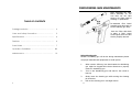
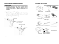
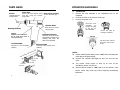
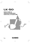
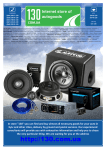
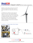
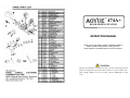
1
7
474A+
DESOLDERING STATION
2
INSTRUCTION MANUAL
Thank you for purchasing 474A+ Desoldering Station.
Please read the manual before using the unit.
Keep manual in accessible place for future reference.
CAUTION
Please remember to remove the pump securing screw
(M4×10 marked red) from the bottom of the station before using. Failure to do so may cause damage to the
unit.
12
DESOLDERING GUN MAINTENANCE
After extracting the Filter
Barrel Assembly we can
now take out the filter
spring or the filter pads for
cleaning or replacement.
TABLE OF CONTENTS
Package Inclusion ……..…………...…………………..
4
Care and Safety Precaution …………………..…..
5
Specifications …….…………..…..………………...…..
6
Features ………...………………………...……...….....
6
Parts Guide ……….……………..…………………...…..
7
Operation Guidelines …..……………..…………..…
8-9
Maintenance …..……………...………………….…..
10
Re-assemble Filter Barrel
assembly and place back to
the de-soldering gun body.
Push the Filter dock back
in place a “click” sound
would signify that the filter
dock is properly secured.
Using Cleaning pin:
Caution: Desoldering gun will be hot during maintenance please
use proper materials and equipments to avoid injuries.
1.
When suction efficiency has deteriorated the desoldering
gun might be clogged follow these directions to properly
clean the desoldering gun.
2.
Turn on the desoldering gun and wait for the nozzle to
heat up.
3.
Slowly insert the cleaning pin while turning the cleaning
pin clockwise.
4.
2
Pull out the cleaning pin in a straight motion.
11
DESOLDERING GUN MAINTENANCE
PACKAGE INCLUSION
Changing nozzle:
●
Unscrew the securing lock and pull out the heater external
housing together with the securing lock, Nozzle can now be
changed. Re-secure nozzle by tighten the securing lock on its
receptacle.
201252 Spring Filter
474 Main Station
Changing Filter pad and Filter Spring:
●
Desoldering Gun
Unlock the filter dock by toggling the filter dock locking
mechanism. The filter dock would push out to allow easy
extraction of the filter barrel assembly which houses the filter
pad, filter spring and filter barrel cap.
Filter Dock
Gun Holder
3022X Filter Pipe
30180X Ceramic
Filter Paper
Filter dock locking
mechanism
Filter Barrel Assembly
3006X Vacuum Cover
20178 Cleaning Drill
201242 Cleaning Pin
Filter Dock
Silicon Grease
Instruction Manual
Power Cord
10
3
302092 Desoldering Tip
302082 Desoldering Tip
CARE and SAFETY PRECAUTIONS
CAUTION: Misuse may cause extensive damage to the unit.
For your own safety, be sure to comply with the following precautions.
DESOLDERING GUN MAINTENANCE
General Guidelines:
●
Before usage dampen the filter pads with a little bit of water
to allow efficient air passage and filter action, re-dampen pads
frequently for maximum efficiency.
Check every component after opening the package whether
●
everything is in good working condition. If there are any
damages suspected , don’t use the item and contact your
Filter Pads
Routinely clean Spring Filter, and replace filter pads when
they are dirty or clogged .
●
dealer.
Upon using, please make sure that the plug is properly
●
Filter Spring
grounded . When moving the unit to another location, be
sure to turn off the power switch and remove the plug.
The solder pathway can be cleaned using the provided Nozzle
cleaning pin, use the cleaning pin when pathway seems
clogged.
●
Do not disassemble/modify unit, high voltage pressure inside
●
unit may cause damages.
●
Do not allow nozzle tip to touch board directly.
●
Unit produces heat, use under ventilated environment.
●
Disconnect plug when not to be used for a long period of
Nozzle cleaning pin
time.
Do not strike or subject to physical shock the main unit or
●
any parts of the system. Use carefully and lightly so as not
Disassembled illustration:
to damage any parts.
Filter Barrel
Be sure the unit is grounded. Always connect power to a
●
Spring Filter
grounded receptacle.
Filter barrel
cap
Filter Pads
Filter Dock
Heating element
assembly
Tip lock cylinder
4
9
De-soldering Gun
Body
Heat guard
assembly
Nozzle
OPERATION GUIDELINES
II. Melt the solder
1.
Power Input :
available in 110V / 220V
* Do not touch nozzle to board.
Power Consumption:
70W
Try to check the inside of the hole and the backside of the PCB
Temperature Range:
150°C - 380°C
Heating Element:
Heating Element
easily then it means that solder is completely melted but do not
Output Voltage:
24V
force it.
Tip to Ground Resistance:
Below 2 Ω
Tip to Ground Potential:
Below 2mV
After checking that solder is completely melted, position the
Suction Flow:
15 l /min (max)
desolder gun then absorb the solder by pulling the trigger.
Vacuum Generator:
Double Cylinder
Vacuum Pressure:
600mm Hg
Station Dimensions:
188(w) x 127(h) x 244(d) mm
Weight:
5.3Kg
Apply the nozzle to the soldered part and melt the solder.
2.
if solder is melted.
3.
Try moving the solder using the desolder gun nozzle, if it moves
III. Absorb the solder
1.
* Be careful not to leave any solder remain in the hole.
2.
SPECIFICATIONS
After fully absorbing all the solder, cool the soldering junction in
order to prevent it from becoming resoldered.
FEATURES
Compact unit with air cylinder type strong suction vacuum
●
pump.
●
Suited for multi-layered PCB reworking.
●
The heating element and tip are designed closely to
guarantee enough temperature during desoldering.
8
5
OPERATION GUIDELINES
PARTS GUIDE
Filter Pipe
Where you trap melted solder Back Holder Assembly
and flux using the ceramic Secures the filter pipe.
paper filter.
Nozzle
Transmit heat for
melting solder.
I.
Connections
1.
Connect the cord assembly of the Desoldering Gun to the
receptacle .
2.
Connect the tube to the vacuum outlet cap.
3.
Connect the power cord.
Insert the cord
assemble
by
keying the plug
to the key on
the receptacle.
Release Knob
Push down to remove
the filter pipe.
Heating Element
Trigger
Pressure Indicator
Squeeze to start absorption.
Do not press when nozzle is
not fully heated up.
Indicates when the nozzle
and heating element need
cleaning and when the
filters need replacing.
Cord Assembly
t
an
Cle
he
pu
h
mp
d
ea
Fully insert the vacuum
tube in the vacuum outlet cap.
Vacuum Tube
Connects to the receptacle
(station).
Secure the plug by
turning it clockwise.
Connects to the vacuum cover
(station).
an
d
ng
fixi
pla
te.
NOTE:
Confirm that the power switch is set to “OFF”, before connecting the
●
power plug to the power supply
Fixing plate
Check if the indicator light lights up when you turn the unit
●
Valve plate
Pump Head
Exhaust Filters
“ON”.
The suction nozzle begins to heat up as soon as the
●
desoldering switch is turned on.
Pump Head
After turning the switch to “ON”, wait for a few minutes (until
●
suction nozzle fully heats up) before beginning desoldering
Valve plate
Fixing plate
6
operations.
7