1
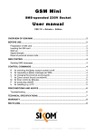
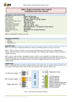
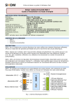
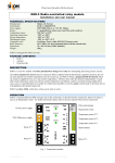
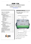
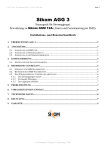
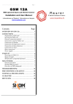
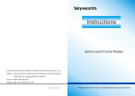
R
Please leave this guide with the end user
Rev 1.3
INS T ALL AT ION AN D US E R M ANU AL
FOR FU SE BO X NO DE G R-3
www.EcoStarter.com
NB!
GR-3 is not a stand-alone product; it is exclusively operated via a Sikom central unit, either
locally or using SMS messages. GR-3 only communicates with Sikom A-Comfort and Sikom GSM
Alarm Controller III.
PA C KAGE C ONT EN TS
•
•
•
GR-3
Antenna
Protection lid
DE S C RIP TIO N
GR-3 is a fuse box module that offers three relays for turning circuits on and off.
Up to three temperature sensors may be connected. When combined with the thermostatic regulation function,
the user can enter desired eco/comfort temperatures into the system to obtain a programmable thermostat
which can easily be toggled between eco- and comfort temperatures. All three relays offer this function.
It is also possible to activate a pulse control mode on all outputs for equipment that should require this.
GR-3 has three LEDs which show when a given relay is switched on.
INS T ALL A T ION
Po wer su ppl y:
Use either 230 VAC (orange terminals) or 12 V DC (black terminals) as power supply, but not both at the same
time! Adjust the protection lids over the terminal strips once all connections are made.
GND
+12V
GR-3
Relay
230V
50Hz
NC
Relay 2
C
NO
NC
Relay 1
Puls
SW
G
T3
G
T2
G
T1
ANT
GND
NO
Temp. sensor 2
Temp. sensor 1
Antenna
NO
C
C
Temp. sensor 3
Relay 3
NC
Fig 1: Connection terminals
www.EcoStarter.com
64-309-36_001-Manual-GR-3_REV1.3-ENG-CH.doc
Page 1 of 1
R
Please leave this guide with the end user
Rev 1.3
Output s/ Rel a ys:
Three potential-free relays are available for control of other appliances, each one supporting a load of 16 A.
They offer thermostatic regulation, on/off or pulse control. Remove the jumper from the Puls pins to make all
three relays produce pulses as control output. Thermostatic regulation will then be disabled. It will nevertheless
remain possible to read off the current temperature from connected sensors.
NB!
When using a 230 VAC power supply, the voltage applied at any relay must also be 230 VAC.
Conversely, a power supply of 12 V DC limits the use of the relays to extra-low voltages (12 V DC or
less). Add auxiliary relays or contactors when necessary.
Remark: the current received at the power supply terminals will only ensure the working of GR-3 itself (e.g., for
communicating with the central unit), but not of the circuits and appliances connected to the relay terminals!
As such, the relays will only act as switches (see fig. 2), not as power supplies.
NO = Normally Open
C = Common
NC = Normally Closed
NO
C
NC
Fig. 2: Relay contacts (in the inactive state)
Te mper ature sen sor inp ut s:
Only temperature sensors can be connected to inputs T1, T2 and T3: no other kind of detector!
Connect temperature sensors for the relays that will be used for thermostatic regulation or for reading off
temperatures: sensor for relay #1 shall be connected to inputs T1 and G, and so on.
Temperature sensor cables must not be laid out alongside 230 V leads and should be kept as far away as possible
from any sources of electrical interferences. Thermostatic regulation and temperature reading may otherwise be
perturbed. Temperature sensors should therefore not be used as floor sensors for floor heating installations, as
this would require shielded twisted pair sensors and filters. Similarly, whereas it is possible to extend a
temperature sensor, it would also induce a loss of precision of measurements.
Ante nna :
The radio antenna is stripped along 16 cm on one end, which must stick vertically out of the fuse box. Connect
the central lead wire to the ANT terminal, and the other one to GND.
GR-3
Fuse box
ANT
GND
Thin, 16 cm long portion of the antenna
cable that is to hang vertically outside of
the fuse box.
Fig. 3: Installation of antenna
www.EcoStarter.com
64-309-36_001-Manual-GR-3_REV1.3-ENG-CH.doc
Page 2 of 2
R
Please leave this guide with the end user
Rev 1.3
RE GIST R A TION WITH THE CEN T RAL U NIT
1. Choose Main menu 8 “Node” on the central unit (GR-3 is viewed as a set of three “Nodes”).
Please refer to the node registration procedure in the user manual of the central unit.
2. Select “New node” and press OK.
3. Press then the SW button of GR-3 for at least 5 seconds.
4. “New node OK!” should then appear on the display of the central unit.
5. All three nodes/relays of GR-3 are registered in a single operation. Write down the three sequential
numbers assigned to the relays of GR-3. These numbers will shortly be displayed by the central unit.
Please write down these numbers for the end user.
IM PO R T ANT INFO R M AT ION R EG ARDIN G F ROS T P RO TE CTIO N
The thermostatic regulation offered by Sikom devices may be used to maintain a base “eco” temperature in your
premises, but must not be taken as an infallible frost protection. Indeed, any electronic equipment is vulnerable
to power surges and other perturbations that may come from the electricity network, e.g. due to lightning. In
such an event, if the electronics is damaged, it may no longer ensure the thermostatic regulation, and hence the
frost protection. Therefore, if frost protection is a critical requirement, it is recommended to add a security
mechanism. These are some alternatives:
1. Use an additional heating system, with its own thermostat, to ensure frost protection in critical premises.
2. Install a protection against power surges and other perturbations from the electricity network.
3. Set up a bimetal thermostat in parallel with your Sikom unit, as shown in the following figure:
N
t
L
Bimetal
thermostat
GSM Fixi
GSM Alarm Controller
GR-1 / GR-3
Fig. 4: Bimetal thermostat mounted in parallel
Sikom and its representatives will not assume liability for any damage due to frost!
TE CHN IC AL S PE CIF ICA T ION S
Manufacturer:
Sikom AS, Norway
Model:
GR-3
Power supply:
230 V AC or 12 V DC
Power consumption:
max 25 mA at 230 V, and max 150 mA at 12 V
Relays:
3 x potential-free relays 230 VAC 16 A (resistive load)
Temperature sensor:
10K NTC at 25°C
Temperature sensing:
-28°C to +49°C ±2°C
Operating temperature:
-20°C to +50°C
Non-operating temperature:
-40°C to +70°C
Radio frequency:
433.9 MHz (for local communication with the central unit)
Dimensions:
70 x 90 x 59 mm (equivalent to 4 DIN modules)
Weight:
250 g
Certification:
CE Nemko
GR-3 is designed for indoor use only.
www.EcoStarter.com
64-309-36_001-Manual-GR-3_REV1.3-ENG-CH.doc
Page 3 of 3
R
Please leave this guide with the end user
Rev 1.3
CO MP LIAN C E WITH IN TE RN A TION AL REGUL ATIONS
This equipment complies with the European R&TTE directive. Further information may be obtained by
contacting either the Swiss importer through www.EcoStarter.com or the manufacturer:
Sikom AS (www.sikom.no)
Jernbanegata 16/18
P.O. Box 223
7601 Levanger
Norway
WA RR ANT Y
Sikom A.S. products are covered by a two years warranty against any faults due to material flaws or
manufacturing errors, which limit or render useless certain functions described for the product. The warranty
requires the customer to present the original bill, with date of purchase and type of equipment clearly readable.
What is covered by the warranty?
During the warranty period, Sikom A.S. reserves the right to repair the product or to replace defective parts with
functionally equivalent parts. If, after several attempts, Sikom A.S. is unable to correct the problem, and the
product does not work as described in the manual, Sikom may elect to refund the purchase price or to replace the
product with a functionally equivalent one. All replaced parts and products become the property of Sikom A.S.
What is not covered by the warranty?
• Indirect damage to life, health, property, revenue and environment caused by circuits and appliances
connected to the units (install and use this product responsibly).
• Costs related to (re)installing, transporting and dismantling units; recycling may be governed by special
rules (see the relevant chapter).
• Damages caused by use outside of the operating conditions specified in the manual.
• Malfunctions caused by transport damages.
• Any unauthorized repair, modification or disassembly.
• Use of non-original parts.
• External factors, such as lightning, power supply issues, mobile network issues, flood damage or fire.
• Units with modified, removed or unreadable serial number.
Sikom assumes no responsibility for any errors that may appear in this manual.
Information contained herein is subject to change without notice.
RE C YCL ING INFO R M AT ION
The WEEE (Waste Electrical and Electronic Equipment) symbol indicates that this product must not be disposed
of along with other household waste. It is the customer's responsibility to dispose of the product properly by
taking it to a designated site for recycling. To locate a recycling/disposal site near you, contact your local city
recycling program, your regular waste disposal service or the agent from whom you purchased this product.
For Switzerland, this product includes in its purchase price a contribution (the advanced recycling fee) to the
SWICO Recycling Warranty, which means that used equipment can be handed in free of charge for recycling.
Collection sites are listed at http://www.swicorecycling.ch.
www.EcoStarter.com
64-309-36_001-Manual-GR-3_REV1.3-ENG-CH.doc
Page 4 of 4