1
3 Ladder Diagram Examples
Part I: Ladder Diagrams
3.1
Across-the-Line, Non-Reversing,
Remote Three-Wire
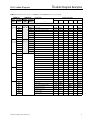
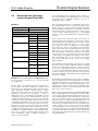
Example 1
Starter Type
Across-the-line, non-reversing
Control Type
Remote three-wire
Device
Name
Assignment
Front Panel Pushbuttons
None
None
Front Panel Light Bars
L1
STOP
L2
RUN
INPUT1
STOP_PB_NC
INPUT2
START_PB_NO
Output
OUTPUT1
M
Timers
TR1
on-delay
Remote Inputs
Flashing Light Bars
TR2
off-delay
FL1
during off-delay
FL2
during on-delay
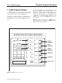
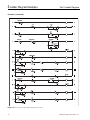
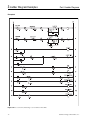
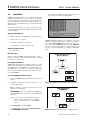
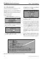
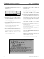
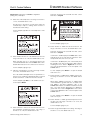
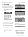
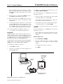
Example 1 and the ladder diagram in Figure 3.2 represent
an across-the-line, non-reversing, remote three-wire motor
application.
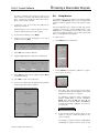
The ladder comprises eight rungs. The topmost rung,
rung 1, latches the state of the START and STOP remote
pushbuttons in control relay CR1. If the normally-closed
remote STOP button (IN1_PB_NC) is depressed, CR1 is deenergized regardless of the state of the START button
(IN2_PB_NO). If the STOP button is relaxed, CR1 is energized as soon as the START button is depressed. Auxiliary
contact CR1 seals in the momentary START pushbutton.
Rung 2 starts the on-delay timer as soon as CR1 is energized. If CR1 is de-energized, the timer is de-energized.
(Although it may seem possible to combine the two rungs
into a single rung avoiding the control relay altogether by
deleting the second rung and replacing CR1 devices with
TR1 devices, it is not possible. Because of the possible
need to retain the state of the momentary remote pushbuttons to ride through a one-second power outage, the latching function of CR1 is retained.)
Rung 4 controls off-delay timer TR2. (Although TR2 provides
a delay between the pressing of the STOP button and the
actual stopping of the motor, which could be realized with
an off-delay type timer, the realization here uses an on-delay
type timer.) A normally-closed instantaneous contact of
timer TR1 controls the state of TR2. If on-delay timer coil
TR1 is energized, TR2 is de-energized; if TR1 is de-energized, TR2 is energized. (A CR1 contact can be used to
replace the TR1 contact without changing operation.)
Rung 3 controls the motor contactor with coil driver output
OUTPUT1. In the cold state, the contacts are in the states
shown, i.e.,
Siemens Energy & Automation, Inc.
•
contact TR2_NCTO (normally-closed, timed-open) is
closed
•
contact TR1_NOTC (normally-open, timed-closed) is
open
•
seal-in contact OUTPUT1_NO (normally-open) is open.
When the START button is depressed, timing relay TR1 in
rung 2 starts to time. When TR1 times out, the TR1_NOTC
contact in rung 3 closes, energizing coil driver output
OUTPUT1 to start the motor and closing seal-in contact
OUTPUT1.
When the STOP button is depressed, timing relay TR1 in
rung 2 is de-energized and its contacts change state. The
motor continues to run even though the TR1_NOTC contact
in rung 3 opens because seal-in contact OUTPUT1 remains
closed.
Contact TR1_NC in rung 4 closes, starting timing relay TR2.
As soon as the timer times out, contact TR2_NCTO in rung
3 opens, de-energizing the OUTPUT1 coil driver, stopping
the motor, and opening seal-in OUTPUT1.
The RUN light bar L2 on the front panel of the SAMMS
device is controlled by another auxiliary OUTPUT1_NO contact as shown in rung 5. The light bar is illuminated as long
as the motor is running.
The STOP light bar L1, as shown in rung 6, is controlled by
the state of the RUN light bar. A NC (normally-closed) auxiliary contact of RUN light bar L2 controls L1. If L2 is on, L1 is
off, and vice versa. (The L2_NC contact in rung 6 can be
replaced by an OUTPUT1_NC contact with no effect on the
operation. Notice also that the SAMMS custom software
permits light bars to have auxiliary contacts.)
Rungs 7 and 8 control the flashing of the RUN and STOP
light bars to indicate on-delay and off-delay timing. The goal
is to have the RUN light bar flash while the on-delay timer is
timing and to have the STOP light bar flash while the offdelay timer is timing.
When on-delay timing relay TR1 is first energized, it starts to
time and its NO instantaneous contact closes. Because
contact TR1_NCTO in rung 7 does not open until TR1 times
out, RUN light bar FL2 flashes. As soon as the timing relay
times out, its NCTO contact opens, ending the flashing.
Rung 8 controls the flashing of the STOP light bar analogously. (In treating the flashing of light bars as outputs distinct from the light bars themselves, the SAMMS software
can eliminate the inclusion of the flashing rate timer in the
ladder diagrams.)
Many of the rungs of the ladder in the remote three-wire
example can be retained for the other control types. In particular, rungs 3 to 8 are common to all standard across-theline, non-reversing starters. The only rungs that change from
one control type to another are those associated directly
with the remote control inputs or the front panel pushbuttons.
11