1
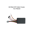
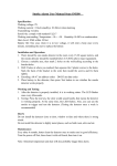
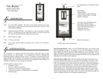
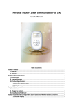
GPS Vehicle Tracker
User Manual
VT810
1. Please read this manual carefully for correct operation.
2. You need to ask a professional to install this product in a safe position of your vehicle. Avoid dangerous or
unsuitable positions, otherwise, harm to the driver or passengers may occur.
3. This manual is just for your reference. The contents and operating steps described in this manual may be different
from that of the actual product, please refer to the actual product.
1. Overview
This vehicle tracker is a remote vehicle positioning device consisting of a GPS module and a GSM/GPRS module, which
is featured by compact size, good concealment and high precision. It can provide the GPS satellite positioning
information, and can also provide the positioning information supported by the GSM base station if the GPS satellite
information is unavailable, and the information about the latitude and longitude coordinates can be sent to the system
platform and the preset mobile phone number. You can make use of these features to locate and manage your vehicle.
2. Definition
2. Installation of SIM card
There is a SIM card slot on the vehicle tracker. Insert the SIM card into the slot as illustrated
3. Operating environment
Operating temperature
-20---65℃
Humidity
5%---95%
Dimensions (mm)
90x53x21
Average current
Less than 80MA ( On Standby)
Weigh
PCBA Size
70g
82×47 mm
Frequency
GSM850/900/1800/1900 Mhz
GPS capability
Hot start: <1.5s
Warm start: <34s
Cold start: <35s(Autonomous)
Position Accuracy: 3.0 m 2D-RMS ,DGPS: 2.5 m
Velocity Accuracy: 0.1m/s,DGPS:0.05m/s
GPS antenna
25×25×2 Built-in
GSM antenna
Built-in
Sensor
G-SENSOR
Button
Turn On/ Off
Interface
2 pieces 4PIN Connector , 2 pieces 2PIN Connector
MIC
External
Relay
External
SOS Button
External
Power
Inner Battery
Input voltage 9-57V
3.7V,350MAH
Speaker
NO
Indicator
2 LED
SIM Slot
PUSH-PUSH
Note:
• The SIM card shall be GSM card
• Make sure to keep enough money in the SIM card account.
• Make sure the SMS service of the SIM card have been subscribed for. To use the real-time tracking by service
platform and positioning by SMS, the user has to subscribe for the GPRS service.
4. Wiring precautions
Power supply, ACC, relay (4-PIN)
(1) The standard power supply of the equipment is 9V-58V DC. Please use the factory supplied power cord, the red
wire is the positive wire, and the black wire is the negative wire. When connecting the negative wire, please ground it
separately, and do not connect it to other ground wires;
(2) ACC wire (green) is used to connect to the vehicle ACC switch. Be sure to connect the ACC wire, because the
vehicle tracker will decide whether to enter the security status depending on the ACC switch status; if the ACC wire is
not connected, the vehicle will be kept in the security or sleep status. Under the status of security or sleep, if vehicle
vibration occurs, the vibration alarm will be triggered. If anti-theft alarm function is not required, you can connect the
ACC wire with the positive wire in parallel to maintain high electrical level.
5. Description of special functions
(1) Security function
If the ACC wire is connected to the ACC switch, this equipment will start the security function automatically in five
minutes after the vehicle engine is turned off. If vehicle vibration occurs within one minute, the equipment will enter
the security status with 1 minute delay, and will enter the security status unless no vehicle vibration occurs.
(2) Sleep mode
After entering the security status, if no vehicle vibration occurs within 20 minutes, this equipment enters the sleep
mode. In the sleep mode, this equipment neither locates nor uploads data, but can send/receive messages and
make/answer calls, so as to achieve maximum energy saving.
(3) Vibration alarm
Under the security status (including the sleep status), if vehicle vibration occurs, this equipment immediately
disconnects the relay and dials the mobile phone number of the vehicle owner to give an alarm; meanwhile, it wakes
up the GPS positioning, and uploads the alarm and location data to the service platform.
(4)Wire cutting alarm
Under the security status, when the main power line of the vehicle tracker is disconnected, the vehicle tracker will
send the wire cutting alarm message to the mobile phone number preset to receive the SOS message and uses the
inner backup battery instead. The backup battery can work 7-10 hours. If the positive wire and negative wire of
equipment are connected together after power line had been cut, the equipment still works normally.
6. Definition of indicators
Red indicator (
) refers to the GPS status
Status
Meaning
Flash at intervals of 1 second
No GPS signal
Flash at intervals of 4 seconds
GPS normal positioning
Blue indicator (
) refers to the GSM/GPRS signal status
Status
Meaning
Flash evey 10 seconds
Normal connection to the server for data uploading
Flash evey 4 seconds
GSM normal standby status
Flash evey 1 second
No GSM signal/initialization/call in progress/incoming call
7. Query by SMS
Send the message 9880000 to the terminal using a mobile phone, and then the terminal will return a message about
the location information with Google map link, click the link by cell phone, then the detailed position will show on
Google map directly.
8. Description of Accessories
(1) Power cord
(2) SOS button
(3) Microphone
(4) Relay
Instruction list
Instruction
Description
Set the center number.
#710#center number#user
password ##
Set the center number through the message sent by a mobile phone. After
successful setting, the terminal returns “&710&Config OK&&”.
e.g.: #710#134xxxxxxxx#0000##
Description: The SOS alarm and low battery alarm messages will be returned
to the number.
Set a preset number
#711#phone number 1#phone
number 2 #phone number 3#user
password##
6660000 (0000 is the factory-set user
password, which can be changed)
9880000 (0000 is the factory-set user
password, which can be changed)
Use a mobile phone to send the setting instruction to the terminal. After
successful setting, the mobile phone will receive the message “&711&CONFIG
OK&&” returned by the terminal.
e.g. 1: #711#134xxxxxxxx###0000## (The format of setting one preset
number)
e.g. 2: #711#134xxxxxxxx#158xxxxxxxx#150xxxxxxxx#0000## (The
format of setting three preset numbers)
Single location query; a message about the latitude and longitude will be
returned
Single location query; a message about the specific location will be returned.
Monitoring function
5550000 (0000 is the factory-set user
password, which can be changed)
The guardian uses a mobile phone to send the message instruction “5550000
(0000 is the user password)” to the vehicle tracker. Upon receipt of the
instruction, the vehicle tracker dials the number of the mobile phone which
has sent the message instruction. After the call is connected, the vehicle
tracker enters the monitoring mode.
Note: The monitoring function can be used only when a preset
number and the center number are set. For the center number
setting and the preset number setting, please refer to the 710 and
711 instruction setting formats described in the Instruction Set
respectively.
Time setting instruction
#567#year, month, day#hour,
minute, second #user password (4
digits)##
e.g.: #567#110513#125820#0000##
Through sending this instruction, the user can change the one-key time
announcement.
Set the timed data uploading function
The factory-set uploading interval of the product is 30, and under this
circumstance, the timed uploading function is turned on. The user can change
the parameter according to his needs.
#730#sampling interval (0 or
15-65535 seconds)#number of
pieces of data uploaded (0 -10)#user
password##
e.g.: #730#20#4#0000##
Description: “20” refers to point sampling every 20 seconds, and the
positioning information will be uploaded after point sampling 4 times, that is,
the uploading interval is 20*4=80 seconds. The user can change the
parameter according to his needs.
Note: The user can send the instruction #730#0#1#0000## to turn off the
GPRS, so as to enter the power saving mode.
Change the user password
#770#new password (4 digits) #old
password (4 digits)##
Description: After the instruction is executed, the terminal will change the
user password according to the user’s requirements. After successful setting,
“&770&CONFIG OK&&” will be returned to the phone; if the password is
wrong, “&770&PASSWORD ER&&” will be returned.
e.g.: #770#1111#0000##. After the instruction is executed, the user
password changes from 0000 to 1111.
Change the user name
#801#letters or numbers (0-20
digits)#user password##
Description: After the instruction is executed, the user name of the terminal
under the GPRS mode will be set according to the requirements. After
successful setting, “&801&CONFIG OK&&” will be returned to the phone; if
the password is wrong, “&801&PASSWORD ER&&” will be returned.
e.g.: #801#13900139000#0000##
Set the APN
#802#APN (letters or numbers, 0-32
digits)#login user name (letters or
numbers, 0-20 digits)#login
password (letters or numbers, 0-20
digits)#user password##
Description: After the instruction is executed, the terminal APN under the
GPRS mode will be set according to the requirements. After successful
setting, “&802&CONFIG OK&&” will be returned to the phone; if the password
is wrong, “&802&PASSWORD ER&&” will be returned.
e.g. 1: #802#CMNET###0000##. After the instruction is executed, the
terminal APN is CMNET, the login user name and password are blank.
e.g. 2: #802#CCDLEN#Guest#Guest#0000##. After the instruction is
executed, the APN is CCDLEN, the login user name is Guest and the login
password is Guest.
Note: The default APN of this product is CMNET.
Set the service address
#803#fixed IP address#port
number#user password##
This instruction is used to set the GPRS center server address. The server
address can either be a fixed IP, whose format is xxx.xxx.xxx.xxx; or a domain
name, whose length is less than 64 bytes. After successful setting,
“&803&Config OK&&” will be returned to the phone; if the password is wrong,
“&803&Password Error&&” will be returned.
e.g.: #803#203.171.233.248#30000#0000##
or it can also be set through the domain name:
e.g.: #803# www.xxx.com#30000#0000##
Set the electronic fence
e.g.: #751#500#5#22.5442N#113.91E#0000## or
#751#500#5#22.5442S#113.91W#0000##
#751#fence radius
(meter)#sampling interval
(minute)#latitude#longitude#user
password##
After successful setting, “&751&CONFIG OK&&” will be returned to the
phone. When the terminal leaves the area, the fence alarm message will be
sent to the center number.
Description: N refers to north latitude, S refers to south latitude, E refers to
east longitude, and W refers west longitude. N/S, E/W is the necessary
condition of the instruction.
Read the electronic fence
Send the instruction “#752#4-digit user password##” to the terminal. After
the instruction is successfully sent, the terminal reads the work status data of
the fence and returns it to the phone. If the password is wrong, “&752&
PASSWORD ER &&” will be returned.
#752#user password##
e.g.: #752#0000##
The following will be returned:
#open:1#lat:22.543685N#lng:113.910633E#distance:500#time:5#status:2
Or
#open:1#lat:22.543685S#lng:113.910633W#distance:500#time:5#status:2
Wherein, open:1 refers to the activation of the fence, open:0 refers to the
deactivation of the fence.
lat: 22.543685N refers to north latitude, 22.543685S refers to south latitude.
lng: 113.910633E refers to east longitude, 113.910633W refers to west
longitude
distance: 500 refers to the radius of the fence.
time:5 refers to the sampling interval.
status:2 refers to that the terminal gets valid satellite data, and the fence
works normally.
status:1 refers to that the fence is activated, but the terminal fails to get valid
satellite data.
status:0 refers to that the electronic fence is not set.
#760#user password##
223+user password
233+user password
Cancel the electronic fence
Turn on the fuel/power cut-off function
Turn off the fuel/power cut-off function
Read the user parameters
#901##
After the instruction is sent, the terminal returns the following message:
#center number#password#user name#user password#preset number 1#
preset number 2#preset number 3# preset number 4#IMEI number##
e.g.:
#134xxxxxxxx#0000#13900139000#0000#@134xxxxxxxx
####356823032080264##
Read the GPRS parameters
#mode#sampling time#number of samples@APN#APN user name#APN
password#IP#port##version number
#902##
e.g.:
#5#0#0@CMNET###121.9.206.148#30000##2011/09/02 18:36
810_V1.XX
#904##
#905##
GPRS connection
GPRS disconnection
Voice switching instruction
#920##
After the instruction is sent, the terminal can switch between English and
Chinese
Short Message
Format of Short Message
Description
IMEI number: SOS (Latitude & longitude
information or base station information)
SOS message
IMEI number: Terminal battery is low, please
charge in time!
Low battery alarm message
IMEI number: Out of the fence (Latitude &
longitude information)
Vibration alarm
Wire cutting message
An alarm message indicating the vehicle is out of
the fence
After the vehicle tracker enters the sleep mode,
the power of the ACC wire is disconnected.
When vehicle vibration occurs, the vehicle
tracker will send the vibration alarm message to
the mobile phone number preset to receive the
SOS message.
When the main power line of the vehicle tracker
is disconnected, the vehicle tracker will send the
wire cutting alarm message to the mobile phone
number preset to receive the SOS message.
Precautions:
This equipment is of non-waterproof design, so please prepare a waterproof bag;
This equipment shall be supported by the GSM network;
Make sure to keep enough money in the SIM card account, so as to avoid inconvenience;
This equipment can not work under power-off status or outside the service area, even you are a registered user;
This equipment supports GPS and GSM/GPRS dual positioning mode, and the results of both shall be deemed
equivalent;
Please use this equipment within the scope permitted by law. Any consequence arising from violation of the laws shall
be solely borne by the user.