1
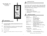
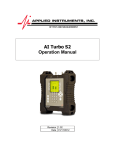
“Sat Buddy”
TM
To LNB
Satellite Signal Meter
User Instructions
LED Display
-Signal Strength
-Current drawn by LNB voltage and
voltage of internal battery or voltage
supplied to IRD port.
DEFINITIONS
LNB:
Low Noise Block amplifier. The portion of the antenna-dish that receives the
high-frequency signal reflected from the dish and then down-converts it to the
L-band (950-2150 MHz).
IRD:
Integrated Receiver Decoder. Also referred to as the set-top box or satellite
receiver. The IRD processes the digital data carried to it by the RF signal and
then provides the baseband picture signal to the television.
RF:
Radio Frequency signals
-First push of the ON/MODE button
selects SIG STRENGTH mode.
-Second push activates audible tone
(still in SIG STRENGTH mode.)
-Third push activates
CURRENT/VOLT mode.
Cable: 75 Ohm coaxial cable
Dish:
Oval shaped antenna hardware mounted on the exterior of the customer’s
premises.
INTRODUCTION
The Sat Buddy™ is a satellite signal meter that measures relative RF signal strength
when connected to a dish antenna. It is designed to be used for installing and
maintaining typical residential satellite systems. In addition to measuring relative RF
signal strength, the Sat Buddy™ also measures LNB current and the voltage being
supplied to the LNB. It can power the LNB using its rechargeable internal battery or it
will allow the IRD power to run through it to the LNB.
Each Sat Buddy™ package contains:
• Sat Buddy™ meter
• Protective rubber boot with clip
• Wall plug transformer for charging battery
• Vehicle power adapter for charging battery in automobile
• Instruction page
Field Replaceable F-81 Double F Female
Barrel
Battery charger plug in.
To IRD (unless using internal battery.
Signal Strength Display: While in the SIG STRENGTH mode, each segment of the
left LED bargraph is equal to 10 segments of the right LED bargraph. Therefore,
when aligning the dish for maximum signal strength, it is more important to have a
higher LED segment illuminated on the left LED bargraph than on the right. Use the
right side LED bar graph for fine alignment purposes and take care to not sacrifice the
illumination of any left side LED segments.
Signal Strength Audible Tone: Press the audible tone button to turn the tone on or
off. There are three beep tones: slow, fast and solid. The audible tone will be a slow
beep if not connected to an LNB and a fast beep or solid tone when connected to an
LNB. For the audible tone to work correctly, the meter has to “learn” the installation’s
maximum and minimum signal level. With the meter connected to the LNB and the
audible tone activated, slowly adjust the horizontal (azimuth) dish alignment over a
wide left/right sweep. The audible tone will change from a solid tone to a fast beep
indicating the meter is “learning and remembering” different signal strengths. After a
forward sweep through the peak signal, slowly sweep back until obtaining a solid tone,
which will indicate the meter is receiving the maximum signal.
BATTERY CHARGING
Over-current detection: If the Sat Buddy™ detects an over-current situation, it will
switch to CURRENT/VOLT mode and flash the highest LED segment on the
CURRENT side. LNB power will be shut off except for re-testing every 4 seconds.
Over or under voltage detection: If the Sat Buddy™ detects a voltage from the IRD,
greater than 20V or less than 10V while in the CURRENT/VOLT mode, it will flash
either the highest or lowest LED segment on the VOLT side, respectively.
DISH ALIGNMENT
1)
2)
3)
Mount and adjust the dish per the instructions of the service provider and
hardware manufacturer.
Connect the Sat Buddy™ to the LNB.
Adjust the dish alignment vertically and horizontally until signal strength is
maximized on the Sat Buddy’s™ display or its audible tone.
SPECIFICATIONS
Frequency Range ....................... 950 to 2150 MHz
Impedance ................................. 75 Ohm
Measurable Input Level............. -48 to –8 dBm total power
-60 to –20 dBm per transponder
Insertion Loss............................ 3 dB (950 to 1450 MHz)
8 dB (1450 to 2150 MHz)
Size (HxWxD)/Weight .............. 6.5” x 2.7” x 1.1”, 1.5 lbs.
(16.5 cm x 6.9 cm x 2.8 cm, 700g)
Operating Temperature.............. 0º to 125º F (-17º to 50º C)
Connectors................................. F81 Double F female (field replaceable)
Power......................................... Uses IRD power when connected, otherwise uses
internal battery. IRD voltage loss through Sat Buddy™
is 1.3 V. Current consumed by Sat Buddy™ in 90 mA.
LNB Power from Sat Buddy™.. Uses internal battery voltage 12 to 16 V, current limited
at 600 mA. Able to continuously power a typical single
LNB (90 to 150 mA) for 1.7 hours.
Internal Battery Pack................. Rechargeable 12 cell NiMH, 350mAh, 12-16 volts
nominal. Automatic shut off when battery voltage drops
to 12.0 volts.
Battery Charge Time ................. 10 hours from wall charger
Wall Charger Output ................. 12 VDC, 200 mA, center pin positive, 2.1mm I.D.
To obtain optimum battery performance, follow these guidelines:
•
Do not use a wall-transformer other than the one provided. Improper voltage
or current input may damage the battery charge circuit and require nonwarranted service work.
WARRANTY
The Applied Instruments Sat Buddy™ has a limited warranty against defects in materials
and workmanship for a period of twelve months. Applied Instruments agrees to repair or
replace any assembly or component (except F-connectors, battery, and protective rubber
boot) found to be defective under normal use during this period. Applied Instruments’
obligation under this warranty is limited solely to repairing the instrument proved to be
defective within the scope of the warranty when returned to the factory. Transportation to
the factory is to be arranged and prepaid by the customer. Authorization by Applied
Instruments is required prior to shipment.
Applied Instruments assumes no liability for secondary charges or consequential damages
and, in any event, Applied Instruments’ liability for breach of warranty under any contract
shall not exceed the purchase price of the instrument shipped, and against which a claim is
made.
Any application recommendations made by Applied Instruments for the use of its products
are based upon tests believed to be reliable, but Applied Instruments makes no warranty of
the results to be obtained. This warranty is in lieu of all other warranties, expressed or
implied, and no representative or person is authorized to represent or assume for Applied
Instruments, any liability in connection with the sale of Applied Instruments products other
than that set forth herein.
Please keep your receipt of purchase to verify purchase date.
If it becomes necessary to have your Sat Buddy™ serviced, contact:
Applied Instruments, Inc.
5230 Elmwood Avenue
Indianapolis, IN 46203
Tel. (317) 782-4331
Fax (317) 786-9665
www.appliedin.com
Signal Measure Mode
•
Signal Level Display ......... Bargraph LEDs left row x 10, right row x 1
•
Audible Tone..................... Dual beep rate with solid tone at peak
Current/Voltage Mode
•
LNB current draw.............. 0 to 500 mA (each LED segment is 50 mA)
•
LNB supply voltage........... 10 to 20 volts (each LED segment is 1V, above 9V)
Specifications subject to change without notice.
Revised 3/2007