1
Cat. No. I560-E2-04
Cat. No. I560-E2-04
RX
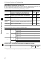
OMRON EUROPE B.V. Wegalaan 67-69, NL-2132 JD, Hoofddorp, The Netherlands.
Tel: +31 (0) 23 568 13 00 Fax: +31 (0) 23 568 13 88 www.industrial.omron.eu
Austria
Tel: +43 (0) 2236 377 800
www.industrial.omron.at
France
Tel: +33 (0) 1 56 63 70 00
www.industrial.omron.fr
Netherlands
Tel: +31 (0) 23 568 11 00
www.industrial.omron.nl
Spain
Tel: +34 913 777 900
www.industrial.omron.es
Belgium
Tel: +32 (0) 2 466 24 80
www.industrial.omron.be
Germany
Tel: +49 (0) 2173 680 00
www.industrial.omron.de
Norway
Tel: +47 (0) 22 65 75 00
www.industrial.omron.no
Sweden
Tel: +46 (0) 8 632 35 00
www.industrial.omron.se
Czech Republic
Tel: +420 234 602 602
www.industrial.omron.cz
Hungary
Tel: +36 (0) 1 399 30 50
www.industrial.omron.hu
Poland
Tel: +48 (0) 22 645 78 60
www.industrial.omron.com.pl
Switzerland
Tel: +41 41 748 13 13
www.industrial.omron.ch
Denmark
Tel: +45 43 44 00 11
www.industrial.omron.dk
Italy
Tel: +39 02 32 681
www.industrial.omron.it
Portugal
Tel: +351 21 942 94 00
www.industrial.omron.pt
Turkey
Tel: +90 (0) 216 474 00 40
www.industrial.omron.com.tr
Finland
Tel: +358 (0) 207 464 200
www.industrial.omron.fi
Middle East & Africa
Tel: +31 (0) 23 568 11 00
www.industrial.omron.eu
Russia
Tel: +7 495 648 94 50
www.industrial.omron.ru
United Kingdom
Tel: +44 (0) 870 752 08 61
www.industrial.omron.co.uk
USER’S MANUAL
Note: Specifications subject to change without notice.
Cat. No. I560-E2-04
RX
Customised to your machine
Model: 3G3RX
200 V Class Three-Phase Input 0.4 to 55 kW
400 V Class Three-Phase Input 0.4 to 132 kW
USER’S MANUAL
Introduction
Introduction
Thank you for choosing the general-purpose Inverter RX Series. This User's Manual (hereinafter
called "this manual") describes the parameter setting methods required for installation/wiring and
operation of the RX model, as well as troubleshooting and inspection methods.
z This manual should be delivered to the actual end user of the product.
z After reading this manual, keep it handy for future reference.
z This manual describes the specifications and functions of the product as well as the relations
between them. You should assume that anything not described in this manual is not possible with
the product.
z Intended readers
This manual is intended for:
Those with knowledge of the workings of electricity (qualified electric engineers or the equivalent),
and also in charge of:
• Introducing the control equipment
• Designing the control system
• Installing and/or connecting the control equipment
• Field management
1
Read and Understand this Manual
Read and Understand this Manual
Please read and understand this manual before using the product. Please consult your OMRON representative
if you have any questions or comments.
Warranty and Limitations of Liability
WARRANTY
OMRON's exclusive warranty is that the products are free from defects in materials and workmanship for a
period of one year (or other period if specified) from date of sale by OMRON.
OMRON MAKES NO WARRANTY OR REPRESENTATION, EXPRESS OR IMPLIED, REGARDING
NON-INFRINGEMENT, MERCHANTABILITY, OR FITNESS FOR PARTICULAR PURPOSE OF THE
PRODUCTS. ANY BUYER OR USER ACKNOWLEDGES THAT THE BUYER OR USER ALONE HAS
DETERMINED THAT THE PRODUCTS WILL SUITABLY MEET THE REQUIREMENTS OF THEIR
INTENDED USE. OMRON DISCLAIMS ALL OTHER WARRANTIES, EXPRESS OR IMPLIED.
LIMITATIONS OF LIABILITY
OMRON SHALL NOT BE RESPONSIBLE FOR SPECIAL, INDIRECT, OR CONSEQUENTIAL
DAMAGES, LOSS OF PROFITS OR COMMERCIAL LOSS IN ANY WAY CONNECTED WITH THE
PRODUCTS, WHETHER SUCH CLAIM IS BASED ON CONTRACT, WARRANTY, NEGLIGENCE, OR
STRICT LIABILITY.
In no event shall the responsibility of OMRON for any act exceed the individual price of the product on
which liability is asserted.
IN NO EVENT SHALL OMRON BE RESPONSIBLE FOR WARRANTY, REPAIR, OR OTHER CLAIMS
REGARDING THE PRODUCTS UNLESS OMRON'S ANALYSIS CONFIRMS THAT THE PRODUCTS
WERE PROPERLY HANDLED, STORED, INSTALLED, AND MAINTAINED AND NOT SUBJECT TO
CONTAMINATION, ABUSE, MISUSE, OR INAPPROPRIATE MODIFICATION OR REPAIR.
2
Read and Understand this Manual
Application Considerations
SUITABILITY FOR USE
OMRON shall not be responsible for conformity with any standards, codes, or regulations that apply to
the combination of products in the customer's application or use of the products.
At the customer's request, OMRON will provide applicable third party certification documents identifying
ratings and limitations of use that apply to the products. This information by itself is not sufficient for a
complete determination of the suitability of the products in combination with the end product, machine,
system, or other application or use.
The following are some examples of applications for which particular attention must be given. This is not
intended to be an exhaustive list of all possible uses of the products, nor is it intended to imply that the
uses listed may be suitable for the products:
• Outdoor use, uses involving potential chemical contamination or electrical interference, or conditions
or uses not described in this manual.
• Nuclear energy control systems, combustion systems, railroad systems, aviation systems, medical
equipment, amusement machines, vehicles, safety equipment, and installations subject to separate
industry or government regulations.
• Systems, machines, and equipment that could present a risk to life or property.
Please know and observe all prohibitions of use applicable to the products.
NEVER USE THE PRODUCTS FOR AN APPLICATION INVOLVING SERIOUS RISK TO LIFE OR
PROPERTY WITHOUT ENSURING THAT THE SYSTEM AS A WHOLE HAS BEEN DESIGNED TO
ADDRESS THE RISKS, AND THAT THE OMRON PRODUCTS ARE PROPERLY RATED AND
INSTALLED FOR THE INTENDED USE WITHIN THE OVERALL EQUIPMENT OR SYSTEM.
PROGRAMMABLE PRODUCTS
OMRON shall not be responsible for the user's programming of a programmable product, or any
consequence thereof.
3
Read and Understand this Manual
Disclaimers
CHANGE IN SPECIFICATIONS
Product specifications and accessories may be changed at any time based on improvements and other
reasons.
It is our practice to change model numbers when published ratings or features are changed, or when
significant construction changes are made. However, some specifications of the products may be
changed without any notice. When in doubt, special model numbers may be assigned to fix or establish
key specifications for your application on your request. Please consult with your OMRON representative
at any time to confirm actual specifications of purchased products.
DIMENSIONS AND WEIGHTS
Dimensions and weights are nominal and are not to be used for manufacturing purposes, even when
tolerances are shown.
PERFORMANCE DATA
Performance data given in this manual is provided as a guide for the user in determining suitability and
does not constitute a warranty. It may represent the result of OMRON's test conditions, and the users
must correlate it to actual application requirements. Actual performance is subject to the OMRON
Warranty and Limitations of Liability.
ERRORS AND OMISSIONS
The information in this manual has been carefully checked and is believed to be accurate; however, no
responsibility is assumed for clerical, typographical, or proofreading errors, or omissions.
4
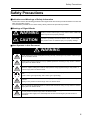
Safety Precautions
Safety Precautions
Indications and Meanings of Safety Information
In this user's manual, the following precautions and signal words are used to provide information to ensure the
safe use of the RX Inverter.
The information provided here is vital to safety. Strictly observe the precautions provided.
Meanings of Signal Words
WARNING
Indicates an imminently hazardous situation which, if not avoided,
is likely to result in serious injury or may result in death. Additionally
there may be severe property damage.
CAUTION
Indicates a potentially hazardous situation which, if not avoided,
may result in minor or moderate injury or in property damage.
Alert Symbols in this Document
WARNING
Turn off the power supply and implement wiring correctly. Not doing so may result in a serious injury
due to an electric shock.
Wiring work must be carried out only by qualified personnel. Not doing so may result in a serious
injury due to an electric shock.
Do not change wiring and slide switches (SW1), put on or take off Digital Operator and optional
devices, replace cooling fans while the input power is being supplied. Doing so may result in a
serious injury due to an electric shock.
Be sure to ground the unit. Not doing so may result in a serious injury due to an electric shock or
fire.
(200-V class: type-D grounding, 400-V class: type-C grounding)
Do not remove the terminal block cover during the power supply and 10 minutes after the power
shutoff.
Doing so may result in a serious injury due to an electric shock.
Do not operate the Digital Operator or switches with wet hands. Doing so may result in a serious
injury due to an electric shock.
Inspection of the Inverter must be conducted after the power supply has been turned off. Not doing
so may result in a serious injury due to an electric shock.
The main power supply is not necessarily shut off even if the emergency shutoff function is
activated.
5
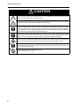
Safety Precautions
CAUTION
Do not connect resistors to the terminals (PD/+1, P/+, N/-) directly. Doing so might result in a smallscale fire, heat generation or damage to the unit.
Install a stop motion device to ensure safety. Not doing so might result in a minor injury. (A holding
brake is not a stop motion device designed to ensure safety.)
Be sure to use a specified type of braking resistor/regenerative braking unit. In case of a braking
resistor, install a thermal relay that monitors the temperature of the resistor. Not doing so might
result in a moderate burn due to the heat generated in the braking resistor/regenerative braking
unit. Configure a sequence that enables the Inverter power to turn off when unusual overheating is
detected in the braking resistor/regenerative braking unit.
The Inverter has high voltage parts inside which, if short-circuited, might cause damage to itself or
other property. Place covers on the openings or take other precautions to make sure that no metal
objects such as cutting bits or lead wire scraps go inside when installing and wiring.
Do not touch the Inverter fins, braking resistors and the motor, which become too hot during the
power supply and for some time after the power shutoff. Doing so may result in a burn.
Take safety precautions such as setting up a molded-case circuit breaker (MCCB) that matches
the Inverter capacity on the power supply side. Not doing so might result in damage to property due
to the short circuit of the load.
Do not dismantle, repair or modify this product.
Doing so may result in an injury.
6
Precautions for Safe Use
Precautions for Safe Use
Installation and Storage
Do not store or use the product in the following places.
•Locations subject to direct sunlight.
•Locations subject to ambient temperature exceeding the specifications.
•Locations subject to relative humidity exceeding the specifications.
•Locations subject to condensation due to severe temperature fluctuations.
•Locations subject to corrosive or flammable gases.
•Locations subject to exposure to combustibles.
•Locations subject to dust (especially iron dust) or salts.
•Locations subject to exposure to water, oil, or chemicals.
•Locations subject to shock or vibration.
Transporting, Installation, and Wiring
•Do not drop or apply strong impact on the product. Doing so may result in damaged parts or malfunction.
•Do not hold by the front cover and terminal block cover, but hold by the fins during transportation.
•Do not connect an AC power supply voltage to the control input/output terminals. Doing so may result in
damage to the product.
•Be sure to tighten the screws on the terminal block securely.
Wiring work must be done after installing the unit body.
•Do not connect any load other than a three-phase inductive motor to the U, V, and W output terminals.
•Take sufficient shielding measures when using the product in the following locations. Not doing so may
result in damage to the product.
Locations subject to static electricity or other forms of noise.
Locations subject to strong magnetic fields.
Locations close to power lines.
Operation and Adjustment
•Be sure to confirm the permissible range of motors and machines before operation because the Inverter
speed can be changed easily from low to high.
•Provide a separate holding brake if necessary.
Maintenance and Inspection
•Be sure to confirm safety before conducting maintenance, inspection or parts replacement.
7
Precautions for Correct Use
Precautions for Correct Use
Installation
• Mount the product vertically on a wall with the product's longer sides upright.
The material of the wall has to be noninflammable such as a metal plate.
Main Circuit Power Supply
• Confirm that the rated input voltage of the Inverter is the same as AC power supply voltage.
Error Retry Function
• Do not come close to the machine when using the error retry function because the machine may abruptly
start when stopped by an alarm.
• Be sure to confirm the RUN signal is turned off before resetting the alarm because the machine may
abruptly start.
Non-Stop Function at Momentary Power Interruption
• Do not come close to the machine when selecting restart in the non-stop function at momentary power
interruption selection (b050) because the machine may abruptly start after the power is turned on.
Operation Stop Command
• Provide a separate emergency stop switch because the STOP key on the Digital Operator is valid only when
function settings are performed.
• When checking a signal during the power supply and the voltage is erroneously applied to the control input
terminals, the motor may start abruptly. Be sure to confirm safety before checking a signal.
Product Disposal
• Comply with the local ordinance and regulations when disposing of the product.
8
Precautions for Correct Use
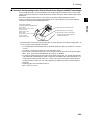
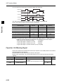
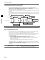
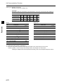
Warning Labels
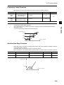
Warning labels are located on the Inverter as shown in the following illustration.
Be sure to follow the instructions.
HITACHI
:$51,1*
/2&$/
5(027(
5($'
:5,7(
(6&
):'
5(9
Warning Description
9
Checking Before Unpacking
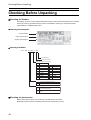
Checking Before Unpacking
Checking the Product
On delivery, be sure to check that the delivered product is the Inverter RX model that you ordered.
Should you find any problems with the product, immediately contact your nearest local sales
representative or OMRON sales office.
zChecking the Nameplate
Inverter model
Input specifications
Output specifications
zChecking the Model
3 G 3 R X -A 2 0 5 5 - E F
F: Built-in filter
E: Europe standard
Max. applicable motor capacity
004
007
015
022
037
055
075
110
150
185
0.4 kW
0.75 kW
1.5 kW
2.2 kW
3.7 kW
5.5 kW
7.5 kW
11 kW
15 kW
18.5 kW
220
300
370
450
550
750
900
11K
13K
22 kW
30 kW
37 kW
45 kW
55 kW
75 kW
90 kW
110 kW
132 kW
Voltage class
2
4
3-phase 200 V AC (200-V class)
3-phase 400 V AC (400-V class)
Enclosure rating
A
Panel-mounting (IP20 min.) or closed
wall-mounting models
B
IP00
Checking the Accessories
Note that this manual is the only accessory included with the RX model.
Mounting screws and other necessary parts must be provided by the user.
10
Revision History
Revision History
A manual revision code appears as a suffix to the catalog number located at the
lower left of the front and back covers.
Cat. No. I560-E2-04
Revision code
Revision code
Revision date
01
April 2009
04
September 2011
Description
First version
Major changes
11
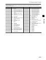
About This Manual
About This Manual
This User's Manual is compiled chapter by chapter for user's convenience as follows.
Understanding the following configuration ensures more effective use of the product.
Overview
13
Chapter 1 Overview
Describes features and names of parts.
Chapter 2 Design
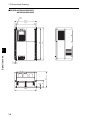
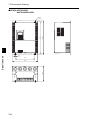
Provides external dimensions, installation dimensions, peripheral device
design/selection instructions, and other information necessary for
design.
Chapter 3 Operation
Describes names of parts, the Inverter's operations, including how to use
the keys on the Digital Operator, and the monitor function.
Chapter 4 Functions
Describes the functions of the Inverter.
Chapter 5
Maintenance
Operations
Describes the causes and their countermeasures if the Inverter fails,
including the solutions to possible troubles (troubleshooting).
Chapter 6
Inspection and
Maintenance
Describes items for periodical inspection and/or maintenance for the
Inverter.
Chapter 7 Specifications
Provides Inverter specifications, as well as the specifications and
dimensions of peripheral devices.
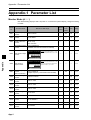
Appendix
Describes the summarized parameter settings as a reference for users
who have used this Inverter and understood the functions.
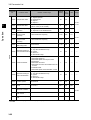
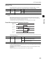
Contents
Introduction..............................................................................................1
Read and Understand this Manual ..........................................................2
Safety Precautions ..................................................................................5
Precautions for Safe Use.........................................................................7
Precautions for Correct Use ....................................................................8
Checking Before Unpacking ....................................................................10
Revision History.......................................................................................11
About This Manual...................................................................................13
Chapter 1 Overview
1-1
1-2
Functions .................................................................................................1-1
Appearance and Names of Parts.............................................................1-4
Chapter 2 Design
2-1
2-2
Installation................................................................................................2-1
Wiring.......................................................................................................2-6
Chapter 3 Operation
3-1
3-2
3-3
3-4
3-5
3-6
3-7
Operation Method ....................................................................................3-3
Test Run Procedure................................................................................. 3-4
Test Run Operation ................................................................................. 3-5
Part Names and Descriptions of the Digital Operator..............................3-8
Keys.........................................................................................................3-11
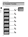
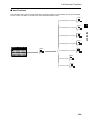
Parameter Transition ...............................................................................3-12
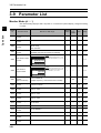
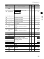
Parameter List ......................................................................................... 3-18
Chapter 4 Functions
4-1
4-2
4-3
4-4
Monitor Mode...........................................................................................4-1
Function Mode ......................................................................................... 4-8
Functions When PG Option Board (3G3AX-PG01) Is Used....................4-119
Communication Function ........................................................................4-139
Chapter 5 Maintenance Operations
5-1
5-2
Protective Functions and Troubleshooting ..............................................5-1
Warning Function.....................................................................................5-9
Chapter 6 Inspection and Maintenance
6-1
Inspection and Maintenance.................................................................... 6-1
Chapter 7 Specifications
7-1
7-2
7-3
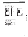
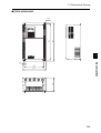
Standard Specification List ......................................................................7-1
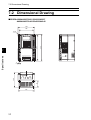
Dimensional Drawing...............................................................................7-6
Options ....................................................................................................7-14
15
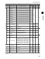
Contents
Chapter App Appendix
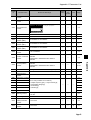
Appendix-1Parameter List ................................................................................. App-1
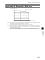
Appendix-2Product Life Curve ........................................................................... App-38
Appendix-3Life Alarm Output............................................................................. App-39
Index
16
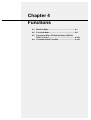
Chapter 1
Overview
1-1 Functions .......................................................... 1-1
1-2 Appearance and Names of Parts .................... 1-4
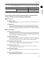
1-1 Functions
1Overview
Overview
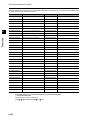
1
1-1 Functions
RX Inverter Models
Rated voltage
Enclosure rating
3-phase 200 V AC
Max. applicable motor capacity
Model
0.4 kW
3G3RX-A2004
0.75 kW
3G3RX-A2007
1.5 kW
3G3RX-A2015
2.2 kW
3G3RX-A2022
3.7 kW
3G3RX-A2037
5.5 kW
3G3RX-A2055
7.5 kW
3G3RX-A2075
11 kW
3G3RX-A2110
15 kW
3G3RX-A2150
18.5 kW
3G3RX-A2185
22 kW
3G3RX-A2220
30 kW
3G3RX-A2300
37 kW
3G3RX-A2370
45 kW
3G3RX-A2450
55 kW
3G3RX-A2550
0.4 kW
3G3RX-A4004
0.75 kW
3G3RX-A4007
1.5 kW
3G3RX-A4015
2.2 kW
3G3RX-A4022
4.0 kW
3G3RX-A4040
5.5 kW
3G3RX-A4055
7.5 kW
3G3RX-A4075
11 kW
3G3RX-A4110
15 kW
3G3RX-A4150
18.5 kW
3G3RX-A4185
22 kW
3G3RX-A4220
30 kW
3G3RX-A4300
37 kW
3G3RX-A4370
45 kW
3G3RX-A4450
55 kW
3G3RX-A4550
75 kW
3G3RX-B4750
90 kW
3G3RX-B4900
110 kW
3G3RX-B411K
132 kW
3G3RX-B413K
IP20
3-phase 400 V AC
IP00
1-1
1-1 Functions
International Standards Models (EC Directives and UL/cUL Standards)
The RX Inverter meets the EC Directives and UL/cUL standard requirements for worldwide use.
Classification
EC Directives
Applicable standard
EN61800-3: 2004
Low-voltage Directive
EN61800-5-1: 2003
Overview
EMC Directive
UL/cUL Standards
1
UL508C
Human-/Environment-friendly, High-performance, General-purpose
Inverters Suitable for Various Advanced Applications
High Performance
High Starting Torque
With the vector control and auto-tuning functions, the RX Series has achieved high starting torque
in excess of 200% at 0.3 Hz.
Trip Suppression
This Inverter features two trip suppression functions: "Overcurrent trip suppression function" to
suppress overcurrent trip during acceleration, and "Overvoltage suppression function during
deceleration" to suppress overvoltage trip during deceleration. Therefore, the RX Series provides
tough operational capabilities regardless of the severe time setting of acceleration and deceleration.
Various Applications
Sensor-less Vector Control at 0 Hz
The RX Series provides sensor-less vector control, which is useful for up/down applications. It can
provide a high torque of 150%, even at a speed reference of 0 Hz (150% torque is available when
the Inverter capacity is increased by one rank). This function contributes to simplification of control
programs and extension of the service life of the brake.
Emergency Shutoff Function
By switching the dedicated switch (SW1) this function enables you to change the multi-function
input (input 3) to the emergency shutoff input. You can directly turn off a motor control power module
without operating the software. This function simplifies construction of safety applications.
Built-in Braking Circuit (up to 22 kW)
The Inverter models with 22 kW or lower capacity incorporate a braking transistor, enabling spacesaving configuration for applications that need rapid acceleration and stop.
Restart Speed Search Function
For a free-running motor (e.g. a fan motor), this function checks the direction of rotation and
frequency, enabling smooth restart of the motor.
High-torque Multi-operation
The RX Series enables balanced torque control for the whole system, in proportion to multiple motor
loads.
Deceleration Stop During Power Failure
During a power failure or momentary power interruption, the RX Series can decelerate and stop a
motor by using the motor braking energy.
1-2
1-1 Functions
Human-/Environment-friendly Features
1
More Simplified Parameter Settings and View
Overview
•Only parameters that have been changed from the default settings can be viewed.
•With the user setting function, only 12 parameters for frequent use can be viewed.
Compliance With Safety Standards
The RX Series meets the requirements of the CE and UL/cUL and complies with various standards.
The RoHS Directive
The standard model meets the requirements of the RoHS Directive.
Easily Meets the Requirements Specified by the Ministry of Land, Infrastructure and
Transport of Japan
The RX Series incorporates a zero-phase reactor (radio noise filter) as a standard specification.
When an optional DC reactor is added, the RX Series meets the requirements specified by the Ministry of Land, Infrastructure and Transport of Japan.
1-3
1-2 Appearance and Names of Parts
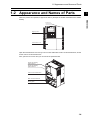
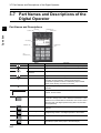
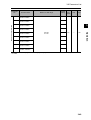
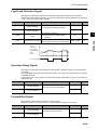
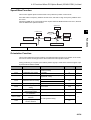
1-2 Appearance and Names of Parts
1
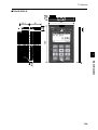
Front cover
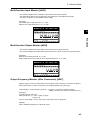
HITACHI
:$51,1*
Digital Operator
/2&$/
5(027(
5($'
:5,7(
(6&
):'
5(9
Terminal block cover
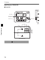
Open the terminal block cover and you can connect cables to the main circuit terminal block, as well
as the control circuit terminal block.
Also, open the front cover and you can mount the optional board.
Position for installing
optional board 1
Position for installing
optional board 2
Control circuit terminal block
Main circuit terminal block
Backing plate
1-4
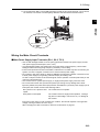
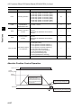
Overview
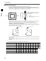
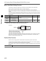
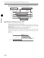
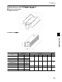
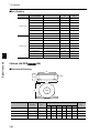
When the product is unpacked, it appears as below. (Example of 3G3RX-A2150/A4150 to A2220/
A4220)
Chapter 2
Design
2-1 Installation ........................................................ 2-1
2-2 Wiring ................................................................ 2-6
2-1 Installation
2Design
2-1 Installation
2
Design
WARNING
Turn off the power supply and implement wiring correctly. Not doing so may result in a serious injury
due to an electric shock.
Wiring work must be carried out only by qualified personnel. Not doing so may result in a serious
injury due to an electric shock.
Do not change wiring and slide switches (SW1), put on or take off Digital Operator and optional
devices, replace cooling fans while the input power is being supplied. Doing so may result in a
serious injury due to an electric shock.
Be sure to ground the unit. Not doing so may result in a serious injury due to an electric shock or fire.
(200-V class: type-D grounding, 400-V class: type-C grounding)
CAUTION
Do not connect resistors to the terminals (PD/+1, P/+, N/-) directly. Doing so might result in a smallscale fire, heat generation or damage to the unit.
Install a stop motion device to ensure safety. Not doing so might result in a minor injury. (A holding
brake is not a stop motion device designed to ensure safety.)
Be sure to use a specified type of braking resistor/regenerative braking unit. In case of a braking
resistor, install a thermal relay that monitors the temperature of the resistor. Not doing so might result
in a moderate burn due to the heat generated in the braking resistor/regenerative braking unit.
Configure a sequence that enables the Inverter power to turn off when unusual overheating is
detected in the braking resistor/regenerative braking unit.
The Inverter has high voltage parts inside which, if short-circuited, might cause damage to itself or
other property. Place covers on the openings or take other precautions to make sure that no metal
objects such as cutting bits or lead wire scraps go inside when installing and wiring.
2-1
2-1 Installation
Safety Information
Installation and Storage
Do not store or use the product in the following places.
•Locations subject to direct sunlight.
•Locations subject to ambient temperature exceeding the specifications.
•Locations subject to relative humidity exceeding the specifications.
•Locations subject to condensation due to severe temperature fluctuations.
•Locations subject to corrosive or flammable gases.
•Locations subject to exposure to combustibles.
•Locations subject to dust (especially iron dust) or salts.
•Locations subject to exposure to water, oil, or chemicals.
•Locations subject to shock or vibration.
2
Design
Transporting, Installation, and Wiring
•Do not drop or apply strong impact on the product. Doing so may result in damaged parts or malfunction.
•Do not hold by the front cover and terminal block cover, but hold by the fins during transportation.
•Do not connect an AC power supply voltage to the control input/output terminals. Doing so may result in
damage to the product.
•Be sure to tighten the screws on the terminal block securely.
Wiring work must be done after installing the unit body.
•Do not connect any load other than a three-phase inductive motor to the U, V, and W output terminals.
•Take sufficient shielding measures when using the product in the following locations. Not doing so may
result in damage to the product.
Locations subject to static electricity or other forms of noise.
Locations subject to strong magnetic fields.
Locations close to power lines.
Precautions for Use
Installation
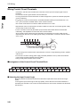
•Install the Inverter vertically on the wall.
Install the Inverter on a nonflammable wall surface material, like metal.
+,7
$&+
,
:$
(6
HITACHI
):
:$51,1*
5($'
5(
51
,1
*
$'
:5
5(
,7
(
9
+,7$&+,
/2&$/
5(027(
5(/2
02&$
7(/
&
'
:5,7(
):'
5($'
5(9
:5,7(
5(9
:$51,1*
(6&
):'
/2&$/
5(027(
(6&
Position for
installing a screw
Main Circuit Power Supply
•Confirm that the rated input voltage of the Inverter matches the AC power supply voltage.
2-2
2-1 Installation
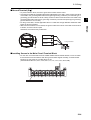
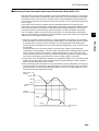
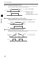
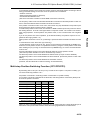
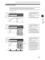
Installation Environment
•Increased ambient temperatures will shorten the life of the Inverter.
•Keep the Inverter away from heating elements (such as a braking resistor, DC reactor, etc.).
If the Inverter is installed in an enclosure, keep the ambient temperature within the range of the
specifications, taking dimensions and ventilation into consideration.
2
Save enough space to prevent the upper
and lower wiring ducts from blocking
cooling airflow.
Inverter
Design
Airflow
*1
Inverter
5 cm min.
5 cm min.
*1 10 cm min.
*2 10 cm min.
Note that replacing the smoothing capacitor
Wall
requires 22 cm or more.
*2
•When several RX models are installed in an enclosure and a ventilation fan is mounted in the
enclosure, be careful about the layout of the Inverters and the air intake apertures.
Depending on the internal layout of the panel, the Inverter's cooling effect may deteriorate,
resulting in an increase in ambient temperature.
Also, use thorough caution in making sure that the Inverter's ambient temperature is within the
allowable operating temperature range.
Ventilation fan
Ventilation fan
Inverter
Inverter
(Correct example)
(Incorrect example)
•Before installing the Inverter, place a cover over all the ventilation openings to shield them from
foreign objects.
After completing the installation process, be sure to remove the covers from the Inverter before
operation.
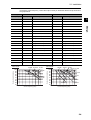
•Below is the heat radiation according to the Inverter capacity.
Inverter capacity (kw)
0.4
0.75
1.5
2.2
3.7
5.5
7.5
11
15
18.5
Load with 70% loss (W)
64
76
102
127
179
242
312
435
575
698
Load with 100% loss (W)
70
88
125
160
235
325
425
600
800
975
85.1
89.5
92.3
93.2
94.0
94.4
94.6
94.8
94.9
95.0
Inverter capacity (kw)
22
30
37
45
55
75
90
110
132
Load with 70% loss (W)
820
1100
1345
1625
1975
2675
3375
3900
4670
Load with 100% loss (W)
1150
1550
1900
2300
2800
3800
4800
5550
6650
Efficiency at rated output (%)
95.0
95.0
95.1
95.1
95.1
95.2
95.2
95.2
95.2
Efficiency at rated output (%)
2-3
2-1 Installation
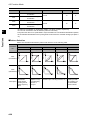
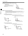
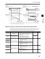
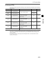
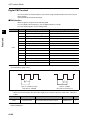
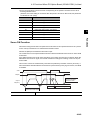
•To raise the carrier frequency, reduce the output current (or derate the rated current) as shown in
the graph below.
Voltage
200-V class
400-V class
Capacity
Max. fc (kHz)
0.4 kW
15
100%
15
100%
0.75 kW
15
100%
15
100%
1.5 kW
15
100%
15
100%
2.2 kW
15
100%
15
100%
3.7 kW
15
100%
15
100%
5.5 kW
15
100%
15
100%
7.5 kW
15
100%
15
100%
11 kW
12
90% (41.4 max.)
15
100%
15 kW
12
95% (60.8 A max.)
14
95% (30.4 A max.)
18.5 kW
10
90% (68.4 A max.)
10
90% (34.2 A max.)
22 kW
7
70% (66.5 A max.)
6
75% (36.0 A max.)
30 kW
5
80% (96.8 A max.)
10
75% (43.5 A max.)
37 kW
10
75% (108.7 A max.)
8
80% (60.0 A max.)
45 kW
5
70% (127.4 A max.)
9
75% (68.2 A max.)
55 kW
5
70% (154 A max.)
6
60% (67.2 A max.)
75 kW
--
--
6
85%(126.7 A max.)
90 kW
--
--
4
75% (132.0 A max.)
110 kW
--
--
6
70% (151.9 A max.)
132 kW
--
--
3
60% (156.0 A max.)
400-V class
15 kW
45,55 kW
30 kW
37 kW
4
6
8
10
12
Carrier frequency (kHz)
14 15
100
95
90
85
80
75
70
65
60
55
0.5 2
Derating at fc = 15 kHz
2
90 kW 75 kW 45 kW
30 kW 15 kW
11 kW
Output current derating
Output current derating
100
95
90
85
80
75
70
65
60
55
0.5 2
22 kW 18.5 kW
Max. fc (kHz)
Design
200-V class
Derating at fc = 15 kHz
18.5 kW
37 kW
132 kW
22 kW
55 kW
110 kW
4
6
8
10
12
14 15
Carrier frequency (kHz)
2-4
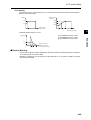
2-1 Installation
Backing Plate
Inverter with 22 kW or Lower Capacity
When running cables, cut the points between the backing plate and unnecessary portions with
nippers or a wire cutter, and remove.
2
Connecting points
Design
Unnecessary portion
Inverter with 30 kW or Higher Capacity
For Connection Without Cable Conduit
Make a cut in the rubber bushing of the backing plate with nippers or a wire cutter, and insert a cable.
Backing plate
Rubber bushing
For Connection With Cable Conduit
Remove the rubber bushing from the conduit connecting portions, and connect the cable conduit.
* Do not remove the rubber bushing unless you connect a cable conduit.
Otherwise, the cable sheath may be damaged by the inner edge of the backing plate, resulting in
short-circuit or ground fault.
2-5
2-2 Wiring
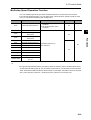
2-2 Wiring
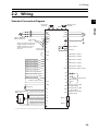
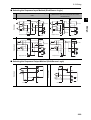
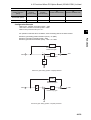
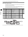
Standard Connection Diagram
2
Braking resistor
(optional)
DC reactor
(optional)
3-phase 200 V AC
3-phase 400 V AC
Short-circuit
wire
N/-
RB
U/T1
S/L2
V/T2
T/L3
W/T3
J51
To wire the control circuit power
supply and main circuit power
supply separately, be sure to
remove the J51 connector
Control circuit
wire first.
power supply
P/+
Design
PD/+1
R/L1
M
R
T
Ro
To
AL1
AL2
AL0
Relay output *1
Common
PLC
11
Multi-function output 1
12
Multi-function output 2
13
Multi-function output 3
14
Multi-function output 4
15
Multi-function output 5
CM1
FW
Multi-function input 1
Multi-function input 2
Multi-function input 3
Multi-function input 4
Multi-function input 5
Multi-function input 6
Multi-function input 7
Multi-function input 8
1
2
3
4
CM2
6
7
SP
SN
8
RS485 communication
RP
Sequence input common
P24
SN
CM1
Thermistor
TH
Frequency setting unit
500 to 2 kΩ
Frequency reference power supply
Frequency reference input (voltage)
Frequency reference auxiliary input (voltage)
Frequency reference input (current)
Frequency reference common
*1
Multi-function output common
5
H
For termination
resistors
AM
Analog monitor output
(voltage output)
AMI
Analog monitor output
(current output)
FM
Digital monitor output
(PWM output)
O
O2
Option 1
OI
L*1
Option 1
L is the common reference for analog input and also for analog output.
2-6
2-2 Wiring
Main Circuit Terminals
Terminal symbol
Terminal name
R/L1, S/L2,
T/L3
Main power supply input
terminal
Connect the input power supply.
U/T1,V/T2,
W/T3
Inverter output terminal
Connect to the 3-phase motor.
PD/+1, P/+
External DC reactor
terminal
Remove the short-circuit bar between terminals "PD/+1"
and "P/+", and connect the optional power factor
improvement DC reactor.
P/+, RB
Braking resistor
connection terminals
Connect optional external braking resistors. (The RB
terminal is provided for the Inverters with 22 kW or lower
capacity.)
P/+, N/-
Regenerative braking
unit connection terminal
Connect optional regenerative braking units.
Ground terminal
Inverter case ground terminal. Connect this terminal to the
ground.
type-D (200-V class), type-C (400-V class)
Design
2
G
Description
Control Circuit Terminal
Frequency reference input
Analog
Terminal
symbol
Terminal name
Description
Specifications
H
Frequency reference
power supply output
+10 V DC power supply for the O terminal.
Allowable load current:
20 mA max.
O
Frequency reference
input
(Voltage)
With a 0 to 10 V DC voltage input, the
frequency reaches the maximum at 10 V.
Set at A014 if the maximum frequency
needs to be achieved at lower than 10 V.
Input impedance 10 kΩ
Allowable input voltage
range:
-0.3 to +12 V DC
O2
Auxiliary frequency
reference input
(Voltage)
With a 0 to ±10 V DC voltage input, the O2
signal is added to the frequency reference
signal of the O or OI terminal. By changing
the setting, the frequency reference can be
input even with the O2 terminal
independently.
Input impedance 10 kΩ
Allowable input voltage
range:
0 to ±12 V DC
OI
Frequency reference
input
(Current)
With a 4 to 20 mA DC current input, the
maximum frequency is set at 20 mA. The OI
signal is only active when the AT terminal is
ON. Allocate the AT function to the multifunction input terminal.
Input impedance 100 Ω
Allowable max. current:
24 mA
L
Frequency reference
common
Common terminal for the frequency setting
signals (O, O2 and OI) and the analog output
terminals (AM and AMI). Do not connect this
terminal to the ground.
Continued to the next page
2-7
2-2 Wiring
Terminal
symbol
Multi-function analog
output
(Voltage)
This terminal outputs a signal selected from
the "0 to 10 V DC Voltage Output" monitor
items: Output frequency, Output current,
Output torque (with/without sign), Output
voltage, Input power, Electronic thermal load
rate, LAD frequency, Motor temperature,
and Fin temperature.
Allowable max. current:
2 mA
Power supply
Digital (contact)
Specifications
2
AMI
Multi-function analog
output
(Current)
This terminal outputs a signal selected from
the "4 to 20 mA DC Current Output" monitor
items: Output frequency, Output current,
Output torque (without sign), Output voltage,
Input power, Electronic thermal load rate,
LAD frequency, Motor temperature, and Fin
temperature.
Allowable load
impedance:
250 Ω max.
FM
Multi-function digital
output
This terminal outputs a signal selected from
the "0 to 10 V DC Voltage Output (PWM)"
monitor items: Output frequency, Output
current, Output torque (without sign), Output
voltage, Input power, Electronic thermal load
rate, LAD frequency, Motor temperature, Fin
temperature, Digital output frequency, and
Digital current monitor.
"Digital output frequency", and "Digital
current monitor" output a digital pulse at 0/10
V DC pulse voltage and 50% duty ratio.
Allowable max. current:
1.2 mA
Max. frequency:
3.6 kHz
P24
Internal 24 V DC
24 V DC power supply for contact input
signal.
When the source logic is selected, this
terminal functions as the contact input
common terminal.
Allowable max. output
current:
100 mA
CM1
Input common
Common terminal for the interface power
supply P24 terminal, thermistor input TH
terminal and digital monitor FM terminal.
When the sink logic is selected, this terminal
functions as the contact input common
terminal. Do not connect this terminal to the
ground.
Monitor output
Monitor output
Description
Design
Analog
AM
Terminal name
Continued to the next page
2-8
2-2 Wiring
RUN command
Terminal
symbol
Contact input
Digital (contact)
Status / Factor
Open collector output
Relay output
Specifications
[Contact input ON
condition]
Voltage between
each input terminal
and the PLC terminal
:18 V DC or more
FW
Forward rotation
command terminal
When the FW signal is ON, the motor runs
forward. When it is OFF, the motor decelerates
and stops.
1
2
3
4
5
6
7
8
Multi-function input
Select 8 functions from among the 61 functions
and allocate them to terminals 1 to 8.
Note: Only terminals 1 and 3 can be used for the
emergency shutoff function. For details,
refer to "Emergency Shutoff Function"
(page 2-10).
Input impedance
between each input
terminal and the PLC
terminal: 4.7 kΩ
Allowable max.
voltage:
Voltage between
each input terminal
and the PLC terminal:
27 V DC
Load current at 27 V
DC power supply
voltage:
Approx. 5.6 mA
PLC
Status, alarm, etc.
Digital (contact)
Description
Function / Selection
Design
2
Terminal name
11
12
13
14
15
Multi-function input
common
The sink and source logic for contact input can
be switched by connecting a short-circuit bar on
the control terminal block.
Short-circuiting P24 and PLC ⇒ Sink logic,
Short-circuiting PLC and CM1 ⇒ Source logic
To activate contact input via an external power
supply, remove the short-circuit bar and
connect PLC terminal to the external interface
circuit.
Multi-function output
Select 5 functions from among 45, and allocate
them to terminals 11 through 15.
If an alarm code is selected in C062, terminals
11 to 13, or terminals 11 to 14 always output an
alarm factor code (e.g. Inverter trip). The signal
between each terminal and CM2 always
corresponds to the sink or source logic.
CM2
Multi-function output
common
Common terminals for multi-function output
terminals 11 to 15.
AL2
AL1
Relay output
AL0
Relay output
common
Select the desired functions from among 45
functions, and allocate them. SPDT contact
output.
By factory default, the relay output (AL2, AL1)
contact selection (C036) is set at NC contact
between AL2-AL0, and NO contact between
AL1-AL0.
Between each
terminal and CM2
Voltage drop 4 V
max. at power-on
Max. allowable
voltage: 27 V DC
Max. allowable
current: 50 mA
Contact max.
capacity
AL2-AL0
250 V AC, 2 A
(Resistance)
0.2 A (Induction)
AL1-AL0
250 V AC, 1 A
(Resistance)
0.2 A (Induction)
Contact min. capacity
100 V AC, 10 mA
5 V DC, 100 mA
Continued to the next page
2-9
2-2 Wiring
Terminal
symbol
External thermistor
input Terminal
Sensor
Analog
Analog input
TH
Terminal name
Description
Allowable input
voltage range
0 to 8 V DC
[Input circuit]
2
8 V DC
10 kΩ
TH
Thermistor
CM1
1 kΩ
Design
Connect an external thermistor to this terminal,
to trip the Inverter when a temperature error
occurs.
The CM1 terminal functions as the common
terminal.
[Recommended thermistor characteristics]
Allowable rated power: 100 mW min.
Impedance at temperature error: 3 kΩ
Temperature error detection level is adjustable
between 0 and 9999 Ω.
Specifications
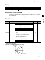
Slide Switch (SW1) Settings
The built-in slide switch is used to enable or disable the emergency shutoff function. (Factory
Default: Disabled)
* For the location of the slide switch, refer to (page 2-12).
Emergency Shutoff Function (Factory Default: Disabled)
•This function is intended to turn off the Inverter output (stop switching the main element) via only
the multi-function input terminal of the hardware circuit without going through the CPU software.
* This function stops switching of the main element.The circuit is not electrically turned off. While the
power supply is ON, do not touch the Inverter terminals and power cable (e.g. motor cable). Doing
so may result in electric shock, injury or ground fault.
•When this function is enabled, the multi-function input terminals 1 and 3 are exclusively used for
this function. No other function can be allocated to these terminals. If another function has been
allocated, it will automatically be disabled, and terminals 1 and 3 are changed to the emergency
shutoff terminals.
Function of multi-function input terminal 1
Reset signal (RS) / NO contact (Fixed)
This signal is used to reset the Inverter, and to reset the emergency shutoff trip [ E37.* ].
Function of multi-function input terminal 3
Emergency shutoff signal (EMR) / NC contact (Fixed)
This signal is used to turn off the Inverter output without using the built-in CPU.
With this signal input, the Inverter activates an emergency shutoff trip [ E37. * ].
* If multi-function input terminal 3 has not been connected or disconnected, or if the signal logic is
not matched, the Inverter activates an emergency shutoff trip [E37. *]. After checking the cable
connection and the signal logic, input the reset signal (RS).
Emergency shutoff trip [ E37. * ] can be reset only by the reset signal (RS) via multi-function input
terminal 1. (It cannot be reset with the Digital Operator.)
•To enable this function, set the slide switch SW1 lever in the Inverter to [ON].
(With the factory default setting, slide switch SW1 is [OFF]. [This function is disabled.])
2-10
2-2 Wiring
* Before operating slide switch SW1, make sure that the input power supply is OFF.
Slide switch SW1 setting and status of multi-function input terminals 1 and 3
Design
2
Slide switch
(SW1)
setting
SW1 OFF
Emergency
shutoff:
Disabled
(factory
default)
SW1 ON
Emergency
shutoff:
Enabled
*5
Turning SW1
on, and then
off
Emergency
shutoff:
Disabled
*3 *5
Multi-function input terminal 1
Multi-function input terminal 3
Multi-function input 1
selection
[ C001 ]
Multi-function input 1
operation selection
[ C011 ]*1
Multi-function input 3
selection
[ C003 ]
Multi-function input 3
operation selection
[ C013 ]*1 *2
[Can be selected
randomly] *4
[Can be selected
randomly] *4
[Can be selected
randomly] *4
[Can be selected
randomly] *4
Factory
default
01 (RV)
Factory
default
00 (NO)
Factory
default
12 (EXT)
Factory
default
00 (NO)
Automatic allocation to multi-function input terminals 1 and 3,
and the input terminal with 18 (RS) setting *3
Fixed
function
(Cannot
be
changed)
18 (RS)
[Can be selected
randomly] *4
Holds
setting
while SW1
is ON.
18 (RS)
Fixed
function
(Cannot
be
changed)
00 (NO)
[Can be selected
randomly] *4
Holds
setting
while SW1
is ON.
00 (NO)
Fixed
function
(Cannot
be
changed)
64 (EMR)
[Can be selected
randomly] *4
Emergency
shutoff
function:
Reset
no
(no
allocation)
Fixed
function
(Cannot
be
changed)
01 (NC)
[Can be selected
randomly] *4
Holds
setting
while SW1
is ON.
01 (NC)
*1. With the terminal with input terminal selection [18 (RS)], NO/NC selection is fixed to [00 (NO)].
*2. When [C003] is [64 (EMR)], [C013] is fixed to [01 (NC)].
*3. If [18 (RS)] has been allocated to a multi-function input terminal (except for 3) other than terminal
1 before switch SW1 is set to "ON", the input terminal selection for the relevant terminal will be
automatically changed to "no (no allocation)" by setting SW1 to "ON". This is done in order to
prevent duplicated allocation of this function. Then, even if SW1 is reset to [OFF], the initial
allocation cannot be restored. The User should Re-allocate the terminal function.
Example) When the multi-function input terminal 2 [C002] is [18 (RS)], setting SW1 to [ON] changes
the [C002] setting to [no (no allocation)]. [18 (RS)] will be allocated to the multi-function
input terminal 1 [C001].
Then, even if SW1 is reset to [OFF], the multi-function input terminal 2 [C002] setting is [no (no
allocation)], and the multi-function input terminal 1 [C001] setting is [18 (RS)].
*4. Input terminal selection [64 (EMR)] cannot be selected with the Digital Operator. When slide
switch SW1 is set to [ON], this function will be automatically allocated.
2-11
2-2 Wiring
*5. Once slide switch SW1 is set to [ON], allocation of multi-function input terminals 1 and 3 will not
be restored, even if SW1 is reset to [OFF] afterward. Re-allocate the terminal function.
2
Design
Slide switch SW1
ON
Slide lever (factory default: OFF)
OFF
ON
Wiring the Main Circuit Terminals
Main Power Supply Input Terminals (R/L1, S/L2, T/L3)
• Use an earth leakage breaker for circuit (wiring) protection between the power supply and the
main power supply terminals (R/L1, S/L2, T/L3).
• An earth leakage breaker may malfunction due to the effect of high frequency. Use an earth
leakage breaker with a large high-frequency sensitivity current rating.
• If the Inverter protection function is activated, a malfunction or accident may have occurred to your
system. Connect a magnetic contactor to turn off the Inverter power supply.
• Do not start or stop the Inverter by switching ON/OFF the magnetic contactor connected on the
Inverter power supply input (primary) side and output (secondary) side.
To start or stop the Inverter via an external signal, use the operation command (FW or RV) on the
control circuit terminal block.
• This Inverter uses a 3-phase power supply. A single-phase power supply cannot be used.
• Do not use this Inverter with a phase loss power input. Doing so may damage the Inverter.
By factory default, the phase loss input protection is disabled. If a phase of power supply input is
interrupted, the Inverter reverts to the following status:
R/L1-phase or T/L3-phase is inter- The Inverter does not operate.
rupted:
S/L2-phase is interrupted:
The Inverter reverts to single-phase operation, causing a
trip (due to undervoltage, overcurrent, etc.) or damage to
the Inverter.
Even if the power input is under a phase loss condition, the internal capacitor is charged with
voltage, causing an electric shock or injury.
When changing the cable connections, refer to the instructions on page 2-1.
2-12
2-2 Wiring
• In the following cases, the internal converter module may be damaged. Use caution to avoid
them:
Imbalance of power supply voltage is 3% or more.
Power supply capacity is ten times or more than the Inverter capacity, and also 500 kVA or more.
Rapid change in power supply voltage.
Design
2
Example) When several Inverters are connected with a short bus.
When the phase advance capacitor is turned on/off.
• Do not turn power on/off more than once every 3 minutes.
Doing so may damage the Inverter.
Inverter Output Terminals (U/T1, V/T2, W/T3)
• For connection of the output terminal, use the applicable cable or a cable with a larger diameter.
Otherwise, the output voltage between the Inverter and the motor may drop.
Particularly during low-frequency output, a voltage drop occurs with the cable, resulting in motor
torque reduction.
• Do not mount a phase advance capacitor or surge absorber. These devices cause the Inverter to
trip, or may cause damage to the capacitor or surge absorber.
• If the cable length exceeds 20 m (particularly, with 400-V class), a surge voltage may be
generated at the motor terminal due to stray capacitance or inductance of the cable, causing the
motor to burn out.
• To connect several motors, provide a thermal relay for each.
• The RC value of each thermal relay should be 1.1 times of the motor rated current. The relay may
trip easily depending on the cable length. In this case, connect an AC reactor to the Inverter
output.
DC Reactor Connection Terminal (PD/+1, P/+)
• This terminal is used to connect the optional DC reactor for power factor improvement.
By factory default, a short-circuit bar has been connected between the terminals PD/+1 and P/+.
Before connecting the DC reactor, remove this short-circuit bar.
• The length of the DC reactor connection cable should be 5 m or less.
If the DC reactor is not used, do not remove the short-circuit bar.
If you remove the short-circuit bar without connecting the DC reactor, no power is supplied to
the Inverter main circuit, disabling operation.
External Braking Resistor Connection Terminal (P/+, RB)/Regenerative Braking
Unit Connection Terminal (P/+, N/-)
• The Inverters with 22 kW or lower capacity incorporate a regenerative braking circuit.
To improve braking capability, mount the optional external braking resistor to this terminal.
Do not mount a resistor whose resistance is lower than the specified value. Doing so may damage
the regenerative braking circuit.
• The Inverters with 30 kW or higher capacity do not incorporate a regenerative braking circuit.
To improve braking capability, the optional regenerative braking unit and braking resistor are
required. In this case, connect the regenerative braking unit terminals (+, -) to the Inverter
terminals (P/+, N/-).
• The cable length should be 5 m or less. Twist the two wires.
• Do not connect any device other than the optional regenerative braking unit or external braking
resistor to this terminal.
2-13
2-2 Wiring
Ground Terminal (G
)
Inverter
Inverter
Inverter
Inverter
Inverter
Inverter
Your ground bolt
Installing Screws in the Main Circuit Terminal Block
• For the main circuit terminal blocks of 3G3RX-A2055/-A2075/-A4055/-A4075, be sure to install
the terminal block screw washers with their grooved sides aligned vertically, as shown below.
Not doing so may result in a contact failure or fire.
(Intended terminals: R/L1, S/L2, T/L3, PD/+1, P/+, N/-, U/T1, V/T2, W/T3, RB)
Terminal block screw washer
2-14
2
Design
• To prevent electric shock, be sure to ground the Inverter and the motor.
• According to the Electric Apparatus Engineering Regulations, the 200-V class Inverter should be
connected to the grounding electrodes under type-D grounding conditions (conventional type 3
grounding: ground resistance 100 Ω or less), the 400-V class Inverter should be connected to the
grounding electrodes under type-C grounding conditions (conventional special type 3 grounding:
ground resistance 10 Ω or less).
• For the ground cable, use the applicable cable or a cable with a larger diameter. Make the cable
length as short as possible.
• When several Inverters are connected, the ground cable must not be connected across several
Inverters, and must not be looped.
Otherwise, the Inverters may malfunction.
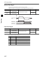
2-2 Wiring
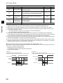
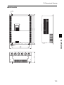
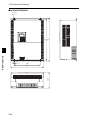
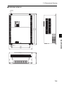
Arrangement of Main Circuit Terminals
The terminal arrangement on the Inverter main circuit terminal block is shown below.
Terminal arrangement
2
Design
Ro
Applicable model
R/L1
S/L2
T/L3
U/T1
PD/+1
P/+
N/-
RB
V/T2
W/T3
G
G
To
CHARGE LED indicator
When not using the DC reactor,
keep the PD/+1 - P/+ short-circuit bar
attached.
PD/+1 - P/+ short-circuit bar
[EMC filter function switching method]
In order to enable the EMC filter
function, set up the plug inserted
into the filter enable pin (J61) and
filter disable pin (J62) as shown in
the table below. Confirm that
electrical power has been
disconnected before performing this
setup. Not doing so may result in
electric shock. Also, use with the
plug inserted.
Dummy plug
(green)
Filter enable pin
(J61)
Short plug
3G3RX-A2004 to A2037
3G3RX-A4004 to A4037
Ro,To: M4
Ground terminal: M4
Others: M4
Filter disable pin (J62)
EMC filter disabled
Filter enable pin (J61)
Dummy plug (green)
EMC filter enabled (factory default)
Short plug
Filter disable pin (J62)
Short plug
Dummy plug (green)
Ro
CHARGE LED indicator
R/L1
S/L2
T/L3
PD/+1
P/+
G
Ground terminal with short-circuit
bar (shaded area) for EMC filter
function switching
To
RB
N/-
U/T1
V/T2
PD/+1 - P/+
short-circuit bar
G
W/T3
3G3RX-A2055, A2075
3G3RX-A4055, A4075
Ro,To: M4
Ground terminal: M5
Others: M5
When not using the DC
reactor, keep the PD/+1 - P/+
short-circuit bar attached.
[EMC filter function switching method]
3G3RX-A2110
3G3RX-A4110
Ro,To: M4
Ground terminal: M6
Others: M5
EMC filter enabled (factory default)
2-15
EMC filter disabled
2-2 Wiring
Terminal arrangement
Applicable model
Ro
To
CHARGE LED indicator
R/L1
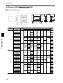
S/L2
T/L3
PD/+1
RB
3G3RX-A2150 to A2185
3G3RX-A4150 to A4220
P/+
N/-
V/T2
PD/+1 - P/+ short-circuit bar
Ground terminal with short-circuit
bar (shaded area) for EMC filter
function switching
2
W/T3
G
Ro,To: M4
Ground terminal: M6
Others: M6
Design
G
U/T1
When not using the DC
reactor, keep the PD/+1 - P/+
short-circuit bar attached.
[EMC filter function switching method]
3G3RX-A2220
Ro,To: M4
Ground terminal: M6
Others: M8
EMC filter enabled (factory default)
EMC filter disabled
Ro
CHARGE LED indicator
3G3RX-A2300
To
G
G
R/L1
S/L2
T/L3
PD/+1
Ground terminal with short-circuit
bar (shaded area) for EMC filter
function switching
P/+
N/-
U/T1
V/T2
W/T3
PD/+1 - P/+ short-circuit bar
When not using the DC reactor,
keep the PD/+1 - P/+
short-circuit bar attached.
[EMC filter function switching method]
Ro, To: M4
Ground terminal: M6
Others: M8
3G3RX-A4300
Ro,To: M4
Ground terminal: M6
Others: M6
3G3RX-A2370
3G3RX-A4370
EMC filter enabled (factory default)
EMC filter disabled
Ro,To: M4
Ground terminal: M8
Others: M8
2-16
2-2 Wiring
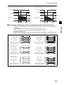
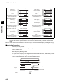
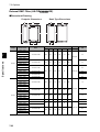
Terminal arrangement
Ro
CHARGE LED indicator
Design
2
Applicable model
To
G
R/L1
G
S/L2
T/L3
PD/+1
P/+
N/-
PD/+1-P/+
short-circuit bar
U/T1
V/T2
W/T3
G
Ground terminal with
short-circuit bar (shaded area)
for EMC filter function switching
When not using the DC
reactor, keep the PD/+1-P/+
short-circuit bar attached.
3G3RX-A2450
3G3RX-A4450
3G3RX-A4550
[EMC filter function switching method]
Ro,To: M4
Ground terminal: M8
Others: M8
EMC filter enabled (factory default)
EMC filter disabled
Ro
CHARGE LED indicator
R/L1
G
S/L2
T/L3
PD/+1
P/+
PD/+1 - P/+
short-circuit bar
When not using the DC
reactor, keep the PD/+1 - P/+
short-circuit bar attached.
N/-
G
To
U/T1
V/T2
G
Ground terminal with
short-circuit bar
(shaded area) for EMC
filter function switching
2-17
3G3RX-A2550
Ro,To: M4
Ground terminal: M8
Others: M10
[EMC filter function switching method]
EMC filter enabled (factory default)
W/T3
EMC filter disabled
2-2 Wiring
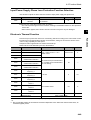
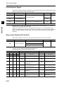
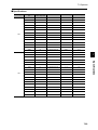
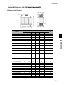
Recommended Cable Size, Wiring Device and Crimp Terminal
Motor
output
(kW)
Applicable
Inverter model
Power
cable
(mm2)
R, S, T,
U, V, W,
PD/+1,
P/+, N/-
0.4
3G3RX-A2004
1.25
1.25
1.25
M4
1.25-4
1.2
(max.1.8)
30 A
0.75
3G3RX-A2007
1.25
1.25
1.25
M4
1.25-4
1.2
(max.1.8)
30 A
1.5
3G3RX-A2015
2
2
2
M4
2-4
1.2
(max.1.8)
2.2
3G3RX-A2022
2
2
2
M4
2-4
1.2
(max.1.8)
3.7
3G3RX-A2037
3.5
3.5
3.5
M4
3.5-4
1.2
(max.1.8)
30 A
5.5
3G3RX-A2055
5.5
5.5
5.5
M5
R5.5-5
2.4
(4.0 max.)
100 A
7.5
3G3RX-A2075
8
8
8
M5
R8-5
2.4
(4.0 max.)
100 A
11
3G3RX-A2110
14
14
14
M6
R14-6
4.0
(4.4 max.)
15
3G3RX-A2150
22
22
22
M6
22-6
4.5
(4.9 max.)
18.5
3G3RX-A2185
30
22
30
M6
38-6
4.5
(4.9 max.)
22
3G3RX-A2220
38
30
38
M8
38-8
8.1
(8.8 max.)
30
3G3RX-A2300
60
(22 × 2)
30
⎯
M8
60-8
8.1
(8.8 max.)
37
3G3RX-A2370
100
(38 × 2)
38
⎯
M8 *1
100-8
8.1
(20.0 max.)
45
3G3RX-A2450
100
(38 × 2)
38
⎯
M8 *1
100-8
8.1
(20.0 max.)
55
3G3RX-A2550
150
(60 × 2)
60
⎯
M10
150-10
19.6
(22.0 max.)
Crimp
terminal
Tightening
torque
N•m
Circuit
breaker or
fuse
Fuse (Type J)
Terminal
screw
size
Fuse (Type J) or Inverse time circuit breaker
Ground
cable
(mm2)
External
braking
resistor
between
PD/+1 and
RB (mm2)
Applicable
device
Earth
leakage
breaker
(ELB)
30 A
30 A
100 A
125 A
125 A
125 A
225 A
225 A
250 A
300 A
2-18
2
Design
200-V class
For Inverter wiring, crimp terminal and terminal screw tightening torque, refer to the table below.
2-2 Wiring
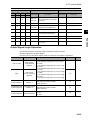
Motor
output
(kW)
Applicable
Inverter model
Power
cable
(mm2)
R, S, T,
U, V, W,
PD/+1,
P/+, N/-
0.4
3G3RX-A4004
1.25
1.25
1.25
M4
1.25-4
1.2
(max.1.8)
20 A
0.75
3G3RX-A4007
1.25
1.25
1.25
M4
1.25-4
1.2
(max.1.8)
20 A
1.5
3G3RX-A4015
2
2
2
M4
2-4
1.2
(max.1.8)
2.2
3G3RX-A4022
2
2
2
M4
2-4
1.2
(max.1.8)
3.7
3G3RX-A4037
2
2
2
M4
2-4
1.2
(max.1.8)
20 A
5.5
3G3RX-A4055
3.5
3.5
3.5
M5
R2-5
2.4
(4.0 max.)
40 A
7.5
3G3RX-A4075
3.5
3.5
3.5
M5
3.5-5
2.4
(4.0 max.)
40 A
11
3G3RX-A4110
5.5
5.5
5.5
M6
R5.5-6
4.0
(4.4 max.)
40 A
15
3G3RX-A4150
8
8
8
M6
8-6
4.5
(4.9 max.)
75 A
18.5
3G3RX-A4185
14
14
14
M6
14-6
4.5
(4.9 max.)
75 A
22
3G3RX-A4220
14
14
14
M6
14-6
4.5
(4.9 max.)
30
3G3RX-A4300
22
22
-
M6
22-6
4.5
(4.9 max.)
37
3G3RX-A4370
38
22
⎯
M8 *1
38-8
8.1
(20.0 max.)
45
3G3RX-A4450
38
22
⎯
M8 *1
38-8
8.1
(20.0 max.)
55
3G3RX-A4550
60
30
⎯
M8 *1
R60-8
8.1
(20.0 max.)
150 A
75
3G3RX-B4750
100
(38 x 2)
38
⎯
M10 *1
100-10
20.0
(22.0 max.)
225 A
90
3G3RX-B4900
100
(38 x 2)
38
⎯
M10 *1
100-10
20.0
(22.0 max.)
225 A
110
3G3RX-B411K
150
(38 x 2)
60
⎯
M10 *1
150-10
20.0
(35.0 max.)
300 A
132
3G3RX-B413K
80 x 2
80
⎯
M10 *1
80-10
20.0
(35.0 max.)
350 A
Crimp
terminal
Tightening
torque
N•m
Circuit
breaker or
fuse
Fuse (Type J)
Terminal
screw
size
Inverse time circuit Breaker
400-V class
Design
2
Ground
cable
(mm2)
External
braking
resistor
between
PD/+1 and
RB (mm2)
Applicable
device
Earth
leakage
breaker
(ELB)
20 A
20 A
75 A
100 A
100 A
150 A
*1. When the cable is connected without using the crimp terminal (bare wires), use the square washer included
with the product.
Note: The cable size is based on the HIV cable (75°C heat resistance).
2-19
2-2 Wiring
Connection for Separating Inverter Control Circuit Power Supply from Main Power Supply
If the Inverter protection circuit is activated to turn off the magnetic contactor of the Inverter input
power supply, the power to the Inverter control circuit is also turned off, and the alarm signal cannot
be kept on.
If the alarm signal must be kept on, use control circuit power supply terminals Ro and To.
Connect control circuit power supply terminals Ro and To to the primary circuit of the magnetic
contactor according to the following procedure.
Design
(Connection method)
Incoming electricity specifications
200-V class:
200 to 240 V (+10%, -15%)
50, 60 Hz ±5%
(282 to 339 V DC)
400-V class:
380 to 480 V (+10%, -15%)
50, 60 Hz ±5%
(537 to 678 V DC)
2
(1) Disconnect the connected wire.
(2) Disconnect the J51 connector.
(3) Connect the control circuit power
cable to the control circuit power
supply terminal block.
* To separate the control circuit power supply (Ro, To) from the main circuit power supply (R/L1, S/
L2, T/L3), observe the following instructions:
• For wiring between terminals Ro and To (terminal screw size: M4), use a cable of 1.25 mm2
or more.
• Connect a 3 A fuse to the control circuit power supply cable.
• If the control circuit power supply (Ro, To) is turned on before the main circuit power supply
(R/L1, S/L2, T/L3), ground fault detection at power-on is disabled.
• To use a DC power supply for the control circuit power supply (Ro, To), set the multi-function
output terminal contact selection (C031 to C036) for the multi-function output terminals (11 to
15) and relay output terminals (AL2, AL1, AL0) to "00". If the multi-function output terminal
contact selection is set to "01", the output signal may chatter when the DC power supply is
turned off.
• Tightening torque for terminals Ro and To
M4: 1.2 N•m (1.4 max.)
2-20
2-2 Wiring
Wiring Control Circuit Terminals
• Terminals L and CM1 are insulated from each other via the input and output signal common
terminals.
Do not short-circuit or ground these common terminals.
Do not ground these common terminals via external equipment. (Check the external equipment
ground conditions.)
2
Design
• For wiring the control circuit terminals, use twisted shielded cables (recommended size: 0.75
mm2), and connect the shielded cable to each common terminal.
• The control circuit terminal connection cables should be 20 m or less.
• Separate the control circuit terminal connection cables from the main circuit cable (power cable)
and the relay control circuit cable.
• For the connection of the TH (thermistor input) terminal, twist cables with the terminal CM1
individually, and separate them from other PLC common cables.
Since a weak current flows through the thermistor, the thermistor connection cable must be
separated from the main circuit cable (power cable). The thermistor connection cable should be
20 m or less.
TH
FW
8
PLC CM1
CM1
6
7
PLC
5
4
Thermistor
• To use a relay for the multi-function output terminal, connect a surge-absorbing diode in parallel
with the coil.
• Do not short-circuit the analog power supply terminals (between H and L) and/or the interface
power supply terminals (between P24 and CM1).
Doing so may result in failure of the Inverter.
Arrangement of the Control Circuit Terminal Block
H
L
O
O2
OI
AM
AMI
FM
P24
TH
PLC
FW
8
CM1
Terminal screw size M3
CM1
7
6
5
3
4
1
2
15
14
CM2
13
12
11
AL0
AL1
AL2
Tightening torque 0.7 N·m (0.8 max.)
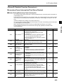
Selecting the Input Control Logic
By factory default the terminal FW and the multi-function input terminal are set to source logic
(PNP).
To change the input control logic to sink logic (PNP), remove the short-circuit bar between the
terminals PLC and CM1 on the control circuit terminal block, and connect it between the terminals
P24 and PLC.
2-21
2-2 Wiring
Selecting the Sequence Input Method (Sink/Source Logic)
When external power supply is used
(Remove the short-circuit bar from the control
terminal block.)
When the Inverter's internal interface power supply is
used
+V
+V
P24
PLC
CM1
PLC
24 V DC
24 V DC
CM1
FW
FW
Design
Sink logic
Short-circuit
bar
2
P24
8
8
COM
COM
Output unit etc.
Source logic
Inverter
COM
P24
Short-circuit PLC
bar
CM1
Output unit etc.
Output unit etc.
Inverter
COM
DC24V
24 V DC
24 V DC
P24
PLC
CM1
FW
FW
8
8
0V
Output unit etc.
Inverter
24 V DC
0V
Inverter
Selecting the Sequence Output Method (Sink/Source Logic)
11
Sink logic
12
COM
24 V DC
Source logic
CM2
24 V DC
COM
11
12
CM2
Inverter
Inverter
2-22
2-2 Wiring
Wiring the Digital Operator
• The RX Series Inverter can be operated with the optional 3G3AX-OP01 or AX-OP05-E as well as
the standard Digital Operator.
• To use the Digital Operator apart from the Inverter body, place an order for the optional cable
3G3AX-CAJOP300-EE (3 m).
2
• The optional cable should be 3 m or less. Using a cable longer than 3 m may cause malfunction.
Design
Conforming to EC Directives
Conforming Standards
•EMC directive
•Low-voltage directive
EN 61800-3: 2004
EN 61800-5-1: 2003
Concept of Conformity
EMC Directive
OMRON products are the electrical devices incorporated and used in various machines or
manufacturing equipment. For this reason, we make efforts to conform our products to their related
EMC standards so that the machines or equipment which have incorporated our products should
easily conform to the EMC standards. The RX models have conformed to the EMC directive EN
61800-3 by following the installation and wiring method as shown below. Your machines or
equipment, however, vary in type, and in addition, EMC performance depends on the configuration,
wiring, or location of the devices or control panels which incorporate the EC directive conforming
products. This in turn does not allow us to confirm the condition and the conformity in which our
products are used. Therefore, we appreciate confirmation of the final EMC conformity for the whole
machine or equipment on your own.
Wiring the Power Supply
•Keep the ground cable as short as possible.
•Keep the cable between the Inverter and the noise filter as short as possible.
Connecting a Motor to the Inverter
•When connecting a motor to the Inverter, be sure to use shield braided cables.
•Keep the cables as short as possible.
Low-voltage Directive
The RX models have conformed to the EMC directive EN61800-5-1 by performing the machine installation and wiring as shown below.
•The RX models are an open type device. Be sure to install it inside the control panel.
•The power supply and voltage (SELV) with reinforced or double insulation should be used for
wiring to the control circuit terminals.
•To satisfy requirements of the LVD (low-voltage) directive, the Inverter must be protected with a
molded case circuit breaker (MCCB) in case a short-circuiting accident occurs. Be sure to install a
molded case circuit breaker (MCCB) on the power supply side of the Inverter.
•Use one molded case circuit breaker (MCCB) per Inverter.
•Use the crimp-type terminal with an insulation sleeve to connect to the main circuit terminals.
2-23
Chapter 3
Operation
3-1
3-2
3-3
3-4
3-5
3-6
3-7
Operation Method ............................................ 3-3
LCD Display ...................................................... 3-4
Test Run Procedure ......................................... 3-5
Operation .......................................................... 3-6
Read/Write function and operation ................ 3-13
Test Run Operation.......................................... 3-14
Part Names and Descriptions of the Digital
Operator ............................................................ 3-17
3-8 Parameter Transition ....................................... 3-19
3-9 Parameter List .................................................. 3-21
3Operation
WARNING
Do not change wiring and slide switches (SW1), put on or take off Digital Operator and optional
devices, replace cooling fans while the input power is being supplied. Doing so may result in a
serious injury due to an electric shock.
Do not remove the terminal block cover during the power supply and 10 minutes after the power
shutoff.
Doing so may result in a serious injury due to an electric shock.
3
Operation
Do not operate the Digital Operator or switches with wet hands. Doing so may result in a serious
injury due to an electric shock.
Inspection of the Inverter must be conducted after the power supply has been turned off. Not doing
so may result in a serious injury due to an electric shock.
The main power supply is not necessarily shut off even if the emergency shutoff function is activated.
CAUTION
Do not touch the Inverter fins, braking resistors and the motor, which become too hot during the
power supply and for some time after the power shutoff. Doing so may result in a burn.
Take safety precautions such as setting up a molded-case circuit breaker (MCCB) that matches the
Inverter capacity on the power supply side. Not doing so might result in damage to property due to
the short circuit of the load.
Safety Information
Operation and Adjustment
• Be sure to confirm the permissible range of motors and machines before operation because the Inverter
speed can be changed easily from low to high.
• Provide a separate holding brake if necessary.
3-1
Precautions for Use
Error Retry Function
•Do not come close to the machine when using the error retry function because the machine may abruptly
start when stopped by an alarm.
•Be sure to confirm the RUN signal is turned off before resetting the alarm because the machine may
abruptly start.
3
Non-Stop Function at Momentary Power Interruption
•Do not come close to the machine when selecting restart in the non-stop function at momentary power
interruption selection (b050) because the machine may abruptly start after the power is turned on.
•Provide a separate emergency stop switch because the STOP key on the Digital Operator is valid only when
function settings are performed.
•When checking a signal with the main power supply applied, if a signal voltage is erroneously applied to the
control input terminals, the motor may start abruptly. Be sure to confirm safety before checking a signal.
3-2
Operation
Operation Stop Command
3-1 Operation Method
3-1 Operation Method
This Inverter has the following operation methods that are selected by the RUN command/
frequency reference settings.
The features and the requirements for each operation method are also given below:
To enter the RUN command/frequency reference via the Digital Operator
This action operates the Inverter via a key sequence of the standard or optional Digital Operator.
When operating the Inverter only via the Digital Operator, the Inverter does not need to be
connected to the control circuit terminal block.
Operation
3
HITACHI
:$51,1*
Digital Operator
/2&$/
5(027(
5($'
:5,7(
(6&
):'
5(9
To enter the RUN command/frequency reference from the control circuit terminal block
This action operates the Inverter by connecting the external signals (from the frequency setting
device, starting switch, etc.) to the control circuit terminal block.
The operation starts by turning ON the RUN command (FW, RV) while the input power supply is
turned ON.
Note: that the frequency can be set using a voltage signal or a current signal from the control circuit
terminal block, which can be selected according to the system. For details, refer to "Control Circuit
Terminal" (page 2-7).
(Requirements for operation)
• RUN command: Switch, Relay etc.
• Frequency reference: External signal (e.g. 0 to 10 V DC, -10 to 10 V DC, 4 to 20 mA)
HITACHI
:$51,1*
Digital Operator
/2&$/
5(027(
5($'
:5,7(
(6&
):'
5(9
Control circuit terminal block
H
Frequency reference
(FREQ adjuster)
O
P24
L
RUN command and (switch)
FW
To enter the RUN command/frequency reference in a combination of Sources
from the Digital Operator and the control circuit terminal block
The RUN command/frequency reference sources can be selected individually from the Digital
Operator as well as the control circuit terminal block.
3-3
3-2 LCD Display
3-2 LCD Display
Backlight
There are two backlight colors in the LCD display, white and orange.
They reflect the state of the inverter as follows:
3
Contents
White
Normal (not related to inverter driving/stop)
Orange
Warning (Parameter mismatch)
White <-> Orange
(Alternate blinking for one second)
Trip (The same as ALARM LED)
Operation
Backlight Color
Details of LCD Display
The first line of LCD monitor always displays the Display Mode, the Motor Selected, the Inverter RUN Status and
the Display Selection.
D is play Mode M otor Selected
Item
Inv erter R U N Status
Display Selection
Content of Display
Content
MONITOR-A
Monitor-A mode
MONITOR-B
Monitor-B mode
FUNCTION
Function mode
TRIP
Trip (error) mode
WARNING
Warning mode (Alarm)
OPTION
LCD Configuration Mode
M1
Motor 1 (SET multifunction = OFF)
M2
Motor 2 (SET multifunction = ON)
STOP
Stopped
FWD
Forward running
REV
Reverse running
ALL
Display all
UTL
Function individual display
USR
User setting display
CMP
Data compare display
BAS
Basic display
Display Mode
Motor selected
Inverter RUN Status
Display Selection (b037)
3-4
3-3 Test Run Procedure
3-3 Test Run Procedure
Item
3
Reference
page
Installation and Mounting Install the Inverter according to the installation conditions.
2-1
• Make sure that the installation conditions are met.
Wiring and Connection
Operation
Description
Connect to the power supply and peripheral devices.
2-6
• Select peripheral devices that meet the specifications, and wire correctly.
Power On
Check the following before turning on the power.
• Make sure that an appropriate power supply voltage is supplied and that the power
input terminals (R/L1, S/L2, and T/L3) are wired correctly.
• 3G3RX-A2: 3-phase 200 to 240 V AC
• 3G3RX-A4: 3-phase 380 to 480 V AC
• Make sure that the motor output terminals (U/T1, V/T2, and W/T3) are connected to
the motor correctly.
• Make sure that the control circuit terminals and the control device are wired correctly
and that all control terminals are turned off.
• Set the motor to no-load status (i.e., not connected to the mechanical system).
• After checking the above, turn on the power.
Display Status Check
Make sure that there are no faults in the Inverter.
• When the power is turned on normally, the display shows:
• RUN LED indicator
: OFF
ALARM LED indicator
: OFF
• POWER LED indicator
: ON
• Data display
: Displays the set value in d001.
• If an error occurs, the error code is displayed on the data display. In this case, refer to
"Chapter 5 Maintenance Operations" and make the necessary changes to remedy.
Parameter Initialization
Initialize the parameters.
• Set parameter No. b084 to "2", and set parameter No. b180 to "1".
Parameter Settings
Set the parameters required for a test run.
• Set the motor capacity selection (H003) and the motor pole number selection (H004).
No-load Operation
Start the no-load motor via the Digital Operator.
• Display parameter No. F001, set the output frequency using the
key,
the
key, and press the
key to confirm the change. Then, press the
rotate the motor.
Actual Load Operation
key and
key to
Connect the mechanical system and operate via the Digital Operator.
• If there are no difficulties with the no-load operation, connect the mechanical system
to the motor and operate via the Digital Operator.
Operation
3-5
Refer to "Chapter 4 Functions", and set the necessary parameters.
3-4 Operation
3-4 Operation
1- Changing the Display Modes
LCD digital operator has four display modes which can be changed from one to another by pressing the
or
key at Navigation level. Moreover, there are 3 other models called Read mode, Write mode and Option mode.
In any display mode, it moves to Read mode or Write mode via
key or
key, and moves to Option mode
after pressing
,
and
at the same time. It returns to display modes via
key.
When pressing
key at Navigation level, a cursor will appear on below layer.
- LCD Navigation levels
To move among the different Navigation levels press keys
The outline of each mode is shown below.
or
.
Monitor Mode A
The "d" group inverter parameters and "F~U" group inverter
parameter are displayed on the same screen in this mode. The
content of "d" group parameter is displayed with big font characters.
The function code such as "F001" and contents of "F~U"
parameters are displayed, without the function name.
Monitor Mode B (Monitor x 4)
In this mode, four "d" group inverter parameters can be displayed at
the same screen. The function codes of these parameters are not
displayed.
Function Mode (setting)
In this mode, "F~U" group parameters can be displayed and set.
Function code, function name, parameter content and parameter
range are shown.
Note: "d" group inverter parameter cannot be set and displayed in
this mode.
Trip Mode
Trip information and warning information are displayed in this
mode. With inverter trip or a warning happens, the trip screen will be
displayed from any display modes.
In Option Mode, Read Mode and Write Mode, the LED or
WARNING LED will light up.
3-6
Operation
Each mode has its own layers, where contents and parameters settings cannot be changed at Navigation level.
3
3-4 Operation
2- Option Mode
1- Please press
,
and
key at the same time to
enter into the OPTION MODE. The cursor will appear in the first row of
the Option Mode menu. Use
or
key to move between the option
Mode menu. To return to the navigator layer, press the
key.
Operation
3
2- Select the Language option and press the
key. The cursor will
appear in the Language option value. Use the
or
key to select
the value to set. Press the
key to store the new value.
Press the
key to cancel the new value.
And then
3- The cursor will appear in the second row. (2. Date and Time).
4- Pressing the
key, it enters to the Date and Time layer. Use
the
or
key for moving between the Day, Month, Year, Hour,
etc...data. When the cursor is over the selected data, pressing
or
key to change the value. The change will be stored after
pressing the
key.
The settings available in this mode are:
1. Language
2. Date and Time
3. Read Lock
4. INV Type Select
5. R/W Storage Mode
6. Backlight Auto-off
7. Backlight Flicker
8. Operator Reset
9. Check Mode
Use
3-7
or
for moving between the Option Mode Menu.
3-4 Operation
3- Details of Option Mode
Item
Content
Setting range
Default
Setting language
Date and Time
Setting Date and Time for the LCD digital
operator
Date: 2000/1/1-2099/12/31
Time: 00:00 - 23:59
Format 1-3
Read Lock
Set "Read lock" enable to disable, in order
to protect the parameter saved in LCD
digital operator from being overwritten.
01: Enable
02: Disable
02
INV Type Select
Please select the correct INV type using
LCD digital operator. otherwise, "COM
ERROR" will be displayed automatically.
01: Type 1 (MX2, LX, RX)
02: Type 2 (JX)
01
R/W Storage Mode
Sets the number of parameter sets for
READ/WRITE mode.
01: Single
02: Quad
02
Backlight Auto-Off
When LCD digital operator remains without
key operations for 1 minute, LCD backlight
will be turned off. When a key is pressed it
will turned on.
The Backlight Auto-Off function does not
work when trip happened.
01: Off
02: 1 minute
01
Backlight Flicker
The Orange backlight will be enabled or
disabled.
01: Enable
02: Disable
01
Operator Reset
Use this function to return to default
settings of LCD digital operator.
The next items will be reset:
1- Language: English
2: Date and Time: 2009/01/01 THU 00:00
01: YES
3: Time format: 01:YY/MM/DD
02: NO
4: Read lock: Disable
5: R/W Storage Mode: Quad
6: Backlight Auto-Off: Off
7: Backlight Flicker: Enable
After this, date and time setting is required.
Check Mode
Check if LED and key etc. are normal or
not.
Key&Led Check, LCD
Check, EEPROM Check,
RTC Check, Serial
Loopback, Debug Mode,
Firmware Version.
01
3
2009/01/01
00:00
1
02
-
Note: Please do not execute the EEPROM check. Otherwise, the data (parameters/Drive program) saved in LCD
digital operator will be erased..
3-8
Operation
Language
01: English
02: German
03: French
04: Spanish
05: Italian
06: Portuguese
07: Japanese
08: Chinese
09: Turkish
10: Russian
3-4 Operation
4- Monitor-A Display Mode
1- Please select monitor mode A by using the
or
key at the
navigation layer. The cursor will be displayed in the Monitor-A pressing
the
key.
Operation
3
2- After that, use the
or
displayed into the Monitor-A.
key to select the function code to be
Use
or
key to move the cursor to the function code (F001 in
this case) and use the
or
key to change the function code.
3- Use the
key to access to the function code value. With the
or
key the value can be changed. The changes will be stored
after pressing the
key or cancelled pressing the
key.
3-9
3-4 Operation
5- Monitor-B Display Mode
1- Please select the Display Mode Monitor-B using the
key at the navigation layer.
or
3
Operation
2- After pressing the
key the cursor will appear on the first row of
the four "d" group inverter parameters. Use the
or
key to
move between the four Monitor-B inverter parameters.
3- Pressing the
key the cursor will appear on the function code of
the "d" inverter parameters selected. Use the
or
key to select
other function code.
• Pressing the
key, the function code is selected, and then
displayed on the Monitor-B display Mode.
• Pressing the
key, the change will be cancelled.
3-10
3-4 Operation
6- Function Mode
1- Please select Function Mode by using the
navigation level.
or
key at the
Operation
3
2- Pressing the
key the cursor will appear in the function code.
Then use the
,
,
or
key to select the function
that will be changed.
3- After that, pressing
value. Use the
or
key the cursor will appear in the parameter
key to select the value to be set.
• To store the parameter value, press the
• Pressing the
3-11
key.
key, changes will be cancelled.
3-4 Operation
7- Trip Mode
1- Select the
layer.
or
key to select trip mode at the navigation
3
Pressing 6 times the
Operation
2- Pressing the
key, the past trip information (6 trip errors) and the
warning information (1 time), that are recorded on the inverter, will be
displayed. Trip information is composed in two pages. For change from
page 1 (P1) to page 2 (P2), press the
or
key.
key, it will be displayed the Warning Mode.
Note: When a trip happens, ALARM LED will be light on. Press the
key to reset the inverter.
3-12
3-5 Read/Write function and operation
3-5 Read/Write function and operation
LCD digital operator can read and save inverter parameter settings and copy them to another inverter.
Specifically LCD digital operator can save four inverter’s parameter sets or one inverter’s parameter set and its
Drive Programming. It can be selected via the R/W Storage Mode in the LCD configuration Option Mode.
Operation
3
Note: If Read operation cannot be executed, please check the Read Lock option in the LCD configuration Option Mode.
R/W Storage Mode - Single READ/WRITE function
When the R/W Storage Mode is selected to "01: Single" (this is done in the LCD configuration: Option Mode), the
function Read or Write is executed immediately after pressing
or
key.
After pressing the
key in any display mode, except Write mode and Option mode, the inverter’s parameter
configuration are read and saved into LCD digital operator Drive Programming program will be transferred to the
LCD digital operator automatically after parameter reading is finished. If the inverter supports Drive Programming
function, it returns to the previous display after read function is completed.
After pressing the
key in any display mode except Read mode and Option mode, the parameter settings
stored in LCD digital operator are transferred to the inverter. If the inverter supports Drive Programming, it will be
transferred to the inverter automatically after the parameter copy is finished. It will return to the previous display
after write function is completed.
R/W Storage Mode - Quad READ function
When the R/W storage mode is selected to 02: Quad option, it will be possible to handle four sets of inverter parameters or read/write an Drive Programming program independently. In this case, LCD digital operator can save
four sets of inverter parameters or one set of inverter parameters and one Drive Programming program. Please
note that one Drive Programming program takes up three sets of inverter parameters, which are No.2, No.3 and
No.4.
Note: Refer to "LCD Line Digital Operator User’s Manual" for more information.
3-13
3-6 Test Run Operation
3-6 Test Run Operation
Power On
Checkpoints Before Turning On the Power
Power On
•After checking the above, turn on the power.
Display Status Check
•When the power is turned on normally, the display shows:
[Normal] RUN LED indicator (during RUN) : ON
ALARM LED indicator
POWER LED indicator
: ON
Data display
: Displays the set value in d001
: OFF
•If an error occurs, refer to "Chapter 5 Maintenance Operations" and make the necessary changes
to remedy.
[Fault]
RUN LED indicator (during RUN) : OFF
ALARM LED indicator
: ON
POWER LED indicator
: ON
Data display
: An error code, such as "E01", is displayed.
(The display varies depending on the type of error.)
3-14
3
Operation
•Make sure that an appropriate power supply voltage is supplied and that the power input terminals
(R/L1, S/L2, and T/L3) are wired correctly.
3G3RX- A2: 3-phase 200 to 240 V AC
3G3RX- A4: 3-phase 380 to 480 V AC
•Make sure that the motor output terminals (U/T1, V/T2, and W/T3) are connected to the motor
correctly.
•Make sure that the control circuit terminals and the control device are wired correctly and that all
control terminals are turned off.
•Set the motor to no-load status (i.e., not connected to the mechanical system).
3-6 Test Run Operation
Parameter Initialization
•Initialize the parameters using the following procedure.
•To initialize the parameters, set parameter b084 to "2" and parameter b180 to "1".
Key sequence
Display example
MONITOR-A
Description
M1-STOP ALL
d001 Output FQ
3
0.00Hz
F001
0.00Hz
FUNCTION
Operation
Power On
M1-STOP ALL
F001
Set Frequency (TM)
Press the Prev. Page or Next Page key until function mode is
displayed.
0 .00Hz
[0.00 – 50.00]
FUNCTION
M1-STOP ALL
F001
Set Frequency (TM)
Press the Set key to enter function mode.
0 .00Hz
[0.00 – 50.00]
FUNCTION
M1-STOP ALL
b084
Initialize Mode
With the Prev. Page, Next Page, Up and Down keys write the
parameter b084.
00:no
[00 – 04]
FUNCTION
M1-STOP ALL
b084
Initialize Mode
Press the Set key to enter b084 parameter.
00:no
[00 – 04]
FUNCTION
M1-STOP ALL
b084
Initialize Mode
With the Prev. Page, Next Page, Up and Down keys put the
parameter b084 to 2.
02:Parameters
[00 – 04]
FUNCTION
M1-STOP ALL
b084
Initialize Mode
Press the Set key to change the parameter b084 to 2.
02:Parameters
[00 – 04]
FUNCTION
M1-STOP ALL
b180
Initialize trigger
With the Prev. Page, Next Page, Up and Down keys write the
parameter b180.
00:No action
[00 – 01]
FUNCTION
M1-STOP ALL
b180
Initialize trigger
00:No action
[00 – 01]
3-15
Press the Set key to enter b180 parameter.
3-6 Test Run Operation
Key sequence
Display example
FUNCTION
Description
M1-STOP ALL
b180
Initialize trigger
With the Prev. Page, Next Page, Up and Down keys put the
parameter b180 to 1.
01:Initialize
[00 – 01]
Initial 01 IM-CT
Press the Set key to change the parameter b180 to 1 and initialize
parameters.
3
Operation
No-load Operation
•Start the no-load motor (i.e., not connected to the mechanical system) using the Digital Operator.
Stopping the Motor
•After completing the no-load operation, press the STOP/RESET key. The motor will stop.
Actual Load Operation
•After checking the operation with the motor in the no-load status, connect the mechanical system
and operate with an actual load.
Connecting the Mechanical System
•After confirming that the motor has stopped completely, connect the mechanical system.
•Be sure to tighten all the screws when fixing the motor axis and the mechanical system.
Operation via the Digital Operator
•Because a possible error may occur during operation, make sure that the STOP/RESET key on
the Digital Operator is easily accessible.
•Use the Digital Operator to operate the Inverter the same way as in no-load operation.
Checking the Operating Status
•After making sure that the operating direction is correct and that the Inverter is operating smoothly
at a slow speed, increase the frequency reference.
•By changing the frequency reference or the rotation direction, make sure that there is no vibration
or abnormal sound from the motor.
Make sure that the output current (output current monitor [d002]) is not excessive.
3-16
3-7 Part Names and Descriptions of the Digital Operator
3-7 Part Names and Descriptions of the
Digital Operator
3
Part Names and Descriptions
RUN LED
POWER LED
WARNING LED
ALARM LED
Operation
HITACHI
LCD display
OPERATION
KEY
REMOTE LED
KEY
ENABLED LED
WARNING
3-17
Name
Function
POWER LED indicator
Light on when the power is supplied to the LCD digital operator.
RUN LED indicator
Light on when the Inverter is runing.
WARNING LED
indicator
Light on when set value is incorrect.
ALARM LED indicator
Light on when the Inverter trips.
Remote LED
Light on when the REMOTE key makes the compulsion
operation function effective. It doesn’t light when the
compulsion operation function is effective by input terminal
OPE. (Press the key more than 2 seconds)
Key Enabled LED
Light on only when operation command is set in LCD digital
operator.
LCD Display
Displays relevant data, such as frequency reference, output
current, and set values.
LOCAL REMOTE key
It changes from Local to Remote mode. Press the key during 2
seconds to change from Local to Remote or Remote to Local.
When it is in Local the OPE led will be ON. Use Local to control
the motor with LCD digital operator keys (Run Fwd, Run Rev
and Stop/Reset).
READ key
It transfers inverter parameters to the LCD digital operator’s
memory.
WRITE key
It copies one Parameter Set or a Parameter Set + Drive
Programming saved in LCD digital operator to the inverter.
ESC key
It returns to the above layer.
SET key
It jumps to the below layer or stores the change introduces on
the edit layer (after that it jumps to the above layer).
3-7 Part Names and Descriptions of the Digital Operator
Name
Function
It is used to move up the cursor, it increases a function code in
1 or increases a parameter value.
DOWN key
It is used to move down the cursor, it decreases a function code
in 1 or it decreases a value.
PREV. PAGE key
It is used to move the cursor to the left, or it moves to previous
mode when the display is a navigation level.
NEXT PAGE key
It is used to move the cursor to the right, or it moves to the next
mode when the display is a navigation level.
FWD RUN key
It is used to run forward the motor only when the operation
command (A002) is reset in Digital operator.
REV RUN key
It is used to run reverse the motor only when the operation
command (A002) is set in Digital operator.
STOP/RESET key
It is used to stop the motor or reset an alarm. It is also possible
to invalidate the STOP key by B087 parameter. Besides it does
not response when LCD digital operator is reading or writing the
parameters from/to the inverter.
Display System and Key Sequence of Each Code
• This section explains the examples of typical operation (Basic display, Complete display) and the
extended function mode U as a special operation.
This operation can be performed when other display modes are selected.
The display indicates the setting of "b038" when the power is turned on. For details, refer to
"Initial Screen Selection (Initial Screen at Power-ON)" (page 4-55).
When "b038 = 1" (factory default), output frequency monitor "d001" is displayed.
Note: The Digital Operator display varies depending on the settings of display selection "b037", initial screen selection "b038", and user parameter automatic setting function selection "b039".
For details, refer to "Display Selection" (page 4-53), "Initial Screen Selection (Initial Screen
at Power-ON)" (page 4-56), "User Parameter Automatic Setting Function" (page 4-57).
Item
Display selection
Initial screen
selection
(Power On)
User parameter
automatic setting
function selection
Function code
b037
Data
Description
00
Complete display
(factory default)
01
Individual display of functions
02
User setting
03
Data comparison display
04
Basic display
00
Screen when the Enter key was pressed last
01
d001 (Output frequency monitor) (factory default)
02
d002 (Output current monitor)
03
d003 (Rotation direction monitor)
04
d007 (Frequency conversion monitor)
05
F001 (Output frequency setting/monitor)
00
Disabled
01
Enabled
b038
(factory default)
b039
3-18
3
Operation
UP key
3-8 Parameter Transition
3-8 Parameter Transition
Operation Example for Complete Display (Default: "b037 = 00")
Displays all parameters.
FUNCTION
3
FUNCTION
M1-STOP ALL
Operation
A001
A001
A001
Frequency source
01:Terminal
Frequency source
A153
01:Terminal
[00 – 10]
FUNCTION
M1-STOP ALL
b001
Restart mode UV
b001
b180
00:TRIP
[00 – 04]
FUNCTION
M1-STOP ALL
C001
C001
Input [1] Function
C169
01:RV
[01 – no]
FUNCTION
M1-STOP ALL
H001
Auto-tuning select
H001
H073
00:OFF
[00 – 02]
FUNCTION
M1-STOP ALL
P001
Error mode OP1 card
P001
P196
00:Trip
[00 – 01]
FUNCTION
M1-STOP ALL
U001
U001
User function 1
no
U012
[d000 – no ]
FUNCTION
M1-STOP ALL
F001
F001
Set Frequency (TM)
0 .00Hz
[0.00 – 50.00]
3-19
M1-STOP ALL
F004
[00 – 10]
3-8 Parameter Transition
User Functions
The extended function mode U is the parameter to optionally register (or automatically record) other extended
function codes, and differs in operation from other extended function modes.
A001
Extended function mode A
A153
b001
Extended function mode B
b180
C169
H001
Extended function mode H
FUNCTION
M1-STOP ALL
U001
P001
U001
Extended function mode P
User function 1
no
H073
U012
P196
[d000 – no ]
d001
Monitor mode
d104
F001
Function mode
F004
3-20
Operation
C001
Extended function mode C
3
3-9 Parameter List
3-9 Parameter List
Monitor Mode (d)
•The default setting displays "d001" at power-on. To select the optional display, change the setting
in "b038".
3
Operation
Parameter
No.
Function name
Monitor or data range
Default
setting
Changes
during
operation
Unit
Page
d001
Output frequency
monitor
0.00 to 400.00
⎯
Yes
Hz
4-1
d002
Output current
monitor
0.0 to 9999.0
⎯
⎯
A
4-1
d003
Rotation direction
monitor
FWD: Forward
STOP: Stop
REV: Reverse
⎯
⎯
⎯
4-1
d004
PID feedback value
monitor
0.00 to 999000.00
(Enabled when the PID function is selected)
⎯
⎯
⎯
4-1
⎯
⎯
⎯
4-2
⎯
⎯
⎯
4-2
MONITOR-A
d005
Multi-function input
monitor
M1-STOP ALL
d005 Input
FW 8 7 6 5 4 3
2
1
00:OFF
MONITOR-A
Multi-function
output monitor
FW, Multi-function input terminals 7, 2, 1: ON
Multi-function input terminals 8, 6, 5, 4, 3: OFF
HLHLLLLHH
H001
d006
Example
M1-STOP ALL
d006 Output
LLLLH H
Example
Multi-function output terminals 12, 11: ON
Relay output terminal AL2, Multi-function
output terminals 15, 14, 13: OFF
AL2 15 14 13 12 11
H001
00:OFF
d007
Output frequency
monitor
(after conversion)
0.00 to 39960.00
(Output frequency × Conversion factor of b086)
⎯
Yes
⎯
4-2
d008
Actual frequency
monitor
-400.00 to 400.00
⎯
⎯
Hz
4-3
d009
Torque reference
monitor
-200. to +200.
⎯
⎯
%
4-3
d010
Torque bias
monitor
-200. to +200.
⎯
⎯
%
4-3
d012
Output torque
monitor
-200. to +200.
⎯
⎯
%
4-3
d013
Output voltage
monitor
0.0 to 600.0
⎯
⎯
V
4-3
d014
Input power monitor 0.0 to 999.9
⎯
⎯
kW
4-4
d015
Integrated power
monitor
0.0 to 999999.9
⎯
⎯
⎯
4-4
d016
Total RUN time
0 to 999999
⎯
⎯
h
4-4
d017
Power ON time
monitor
0 to 999999
⎯
⎯
h
4-4
d018
Fin temperature
monitor
-020. to 200.0
⎯
⎯
°C
4-4
3-21
3-9 Parameter List
Parameter
No.
Function name
d019
Motor temperature
monitor
Monitor or data range
-020. to 200.0
MONITOR-A
d022
Life assessment
monitor
M1-STOP ALL
Default
setting
Changes
during
operation
Unit
Page
⎯
⎯
°C
4-5
⎯
⎯
⎯
4-5
1: Main circuit board capacitor service life
2: Cooling fan rpm reduction
d022 Life(C/F)
LL
3
2 1
H001
00:OFF
Program counter
0 to 1024
⎯
⎯
⎯
⎯
d024
Program number
0 to 9999
⎯
⎯
⎯
⎯
d025
Drive programming
monitor (UM0)
-2147483647 to 2147483647
⎯
⎯
⎯
⎯
d026
Drive programming
monitor (UM1)
-2147483647 to 2147483647
⎯
⎯
⎯
⎯
d027
Drive programming
monitor (UM2)
-2147483647 to 2147483647
⎯
⎯
⎯
⎯
d028
Pulse counter
monitor
0 to 2147483647
⎯
⎯
⎯
4-5
d029
Position command
monitor
-1073741823 to 1073741823 when HAPR is
selected
-268435456 to 268435456 when APR2 is
selected.
⎯
⎯
⎯
4-5
d030
Current position
monitor
-1073741823 to 1073741823 when HAPR is
selected
-268435456 to 268435456 when APR2 is
selected.
⎯
⎯
⎯
4-5
4-132
d031
Clock
Setting Data and Time for the LCD digital operator
⎯
⎯
⎯
⎯
d060
Inverter mode
00 to 01
⎯
⎯
⎯
⎯
d080
Fault frequency
monitor
0 to 65535
⎯
⎯
Time
4-5
d081
Fault monitor 1 (Latest)
d082
Fault monitor 2
d083
Fault monitor 3
d084
Fault monitor 4
d085
Fault monitor 5
d086
Fault monitor 6
d090
Warning monitor
Warning code
0 to 385
⎯
⎯
⎯
4-6
d102
DC voltage monitor
0.0 to 999.9
⎯
⎯
V
4-6
d103
Regenerative
braking load rate
monitor
0.0 to 100.0
⎯
⎯
%
4-6
d104
Electronic thermal
monitor
0.0 to 100.0
⎯
⎯
%
4-7
4-6
Error code (condition of occurrence)
→Output frequency [Hz] → Output current [A]
→Internal DC voltage [V]
→RUN time [h]
→ON time [h]
4-6
⎯
⎯
⎯
4-6
4-6
4-6
4-6
3-22
Operation
d023
3-9 Parameter List
Basic Function Mode (F)
Parameter
No.
Operation
3
Function name
Monitor or data range
Default
setting
Changes
during
operation
Unit
Page
⎯
Yes
Hz
4-8
F001
Output frequency
setting/monitor
0.0/Starting frequency to 1st/2nd/3rd max.
frequency
0.00 to 400.00
F002
Acceleration time 1
0.01 to 3600.00
30.00
Yes
s
4-8
F202
* 2nd acceleration
time 1
0.01 to 3600.00
30.00
Yes
s
4-8
F302
* 3rd acceleration
time 1
0.01 to 3600.00
30.00
Yes
s
4-8
F003
Deceleration time 1
0.01 to 3600.00
30.00
Yes
s
4-8
F203
* 2nd deceleration
time 1
0.01 to 3600.00
30.00
Yes
s
4-8
F303
* 3rd deceleration
time 1
0.01 to 3600.00
30.00
Yes
s
4-8
F004
Operator rotation
direction selection
00: (Forward)
01: (Reverse)
00
No
⎯
4-9
* 2nd/3rd control is displayed when "SET(08)/SET3(17)" is allocated to one of multi-function inputs from C001
to C008.
3-23
3-9 Parameter List
Extended Function Mode
Changes
during
operation
Unit
Page
Frequency reference
selection
00: Digital Operator (FREQ adjuster)
(Enabled when 3G3AX-OP01 is used.)
01: Terminal
02: Digital Operator (F001)
03: ModBus communication
04: Option 1
05: Option 2
06: Pulse train frequency
07: Drive programming
10: Operation function result
02
No
⎯
4-10
4-138
A002
RUN command
selection
01: Terminal
02: Digital Operator (F001)
03: ModBus communication
04: Option 1
05: Option 2
02
No
⎯
4-11
A003
Base frequency
30. to Maximum frequency [A004]
50.
A203
* 2nd base frequency 30. to 2nd maximum frequency [A204]
50.
A303
* 3rd base frequency
30. to 3rd maximum frequency [A304]
50.
A004
Maximum frequency
30. to 400.
50.
A204
* 2nd maximum
frequency
30. to 400.
50.
A304
* 3rd maximum
frequency
30. to 400.
50.
Basic setting
A001
Function name
Monitor or data range
4-11
4-110
No
Hz
4-11
No
Hz
4-12
* 2nd/3rd control is displayed when "SET(08)/SET3(17)" is allocated to one of multi-function inputs from C001
to C008.
3-24
3
Operation
Default
setting
Parameter
No.
3-9 Parameter List
Monitor or data range
Default
setting
Changes
during
operation
Unit
Page
O/OI selection
00: Switches between O/OI via terminal AT
01: Switches between O/O2 via terminal AT
02: Switches between O/FREQ adjuster via
terminal AT
(Enabled only when 3G3AX-OP01 is
used)
03: Switches between OI/FREQ adjuster via
terminal AT
(Enabled only when 3G3AX-OP01 is
used)
04: Switches between O2/FREQ adjuster via
terminal AT
(Enabled only when 3G3AX-OP01 is
used)
00
No
⎯
4-12
A006
O2 selection
00: O2 only
01: O/OI auxiliary frequency reference
(not reversible)
02: O/OI auxiliary frequency reference
(reversible)
03: O2 disabled
03
No
⎯
4-12
A011
O start frequency
0.00 to 400.00
0.00
No
Hz
A012
O end frequency
0.00 to 400.00
0.00
No
Hz
A013
O start ratio
0. to O end ratio
0.
No
%
A014
O end ratio
O start ratio to 100.
100.
No
%
A015
O start selection
00: External start frequency
(A011 set value)
01: 0 Hz
01
No
⎯
A016
O, O2, OI sampling
1. to 30.
31. (with 500 ms filter ± 0.1 Hz hysteresis)
31.
No
⎯
4-15
A017
Drive Programming
Selection
0: Disabling
1: PRG Terminal
2: Always
00
No
⎯
⎯
Parameter
No.
A005
Analog input, Others
Operation
3
Function name
4-14
* 2nd/3rd control is displayed when "SET(08)/SET3(17)" is allocated to one of multi-function inputs from C001
to C008.
3-25
3-9 Parameter List
Function name
Monitor or data range
Default
setting
Changes
during
operation
Unit
Page
00
No
⎯
4-16
A019
Multi-step speed
selection
00: Binary: 16-step selection with 4 terminals
01: Bit: 8-step selection with 7 terminals
A020
Multi-step speed
reference 0
0.0/Starting frequency to Max. frequency
6.00
Yes
Hz
A220
* 2nd multi-step
speed reference 0
0.0/Starting frequency to 2nd Max. frequency
6.00
Yes
Hz
A320
* 3rd multi-step speed
0.0/Starting frequency to 3rd Max. frequency
reference 0
6.00
Yes
Hz
A021
Multi-step speed
reference 1
0.00
A022
Multi-step speed
reference 2
0.00
A023
Multi-step speed
reference 3
0.00
A024
Multi-step speed
reference 4
0.00
A025
Multi-step speed
reference 5
0.00
A026
Multi-step speed
reference 6
0.00
A027
Multi-step speed
reference 7
0.00
A028
Multi-step speed
reference 8
Yes
Hz
A029
Multi-step speed
reference 9
0.00
A030
Multi-step speed
reference 10
0.00
A031
Multi-step speed
reference 11
0.00
A032
Multi-step speed
reference 12
0.00
A033
Multi-step speed
reference 13
0.00
A034
Multi-step speed
reference 14
0.00
A035
Multi-step speed
reference 15
0.00
0.0/Starting frequency to Max. frequency
0.00
4-8
4-16
3
Operation
Multi-step speed, Jogging
Parameter
No.
4-16
* 2nd/3rd control is displayed when "SET(08)/SET3(17)" is allocated to one of multi-function inputs from C001
to C008.
3-26
3-9 Parameter List
Parameter
No.
Monitor or data range
Jogging frequency
0.00/Starting frequency to 9.99
A039
Jogging stop
selection
00: Free running on jogging stop/
Disabled in operation
01: Deceleration stop on jogging stop/
Disabled in operation
02: DC injection braking on jogging stop/
Disabled in operation
03: Free running on jogging stop/
Enabled in operation
04: Deceleration stop on jogging stop/
Enabled in operation
05: DC injection braking on jogging stop/
Enabled in operation
A041
Torque boost
selection
Default
setting
Changes
during
operation
Unit
6.00
Yes
Hz
00
No
⎯
No
⎯
Yes
%
Page
4-18
00
00: Manual torque boost
01: Automatic torque boost
A241
* 2nd torque boost
selection
A042
Manual torque boost
voltage
A242
* 2nd manual torque
boost voltage
A342
* 3rd manual torque
boost voltage
1.0
A043
Manual torque boost
frequency
5.0
A243
* 2nd manual torque
boost frequency
A343
* 3rd manual torque
boost frequency
00
1.0
0.0 to 20.0
1.0
4-19
V/f characteristics
Operation
3
Multi-step speed, Jogging
A038
Function name
0.0 to 50.0
5.0
%
No
⎯
4-21
Yes
%
4-24
5.0
V/f characteristics
selection
00: Constant torque characteristics (VC)
01: Special reduced torque characteristics
(special VP)
02: Free V/f characteristics
03: Sensorless vector control (SLV)
04: 0-Hz sensorless vector control
05: Sensor vector control (V2)
A244
* 2nd V/f
characteristics
selection
00: Constant torque characteristics (VC)
01: Special reduced torque characteristics
(special VP)
02: Free V/f characteristics
03: Sensorless vector control (SLV)
04: 0-Hz sensorless vector control
00
A344
* 3rd V/f
characteristics
selection
00: Constant torque characteristics (VC)
01: Special reduced torque characteristics
(special VP)
00
A045
Output voltage gain
20. to 100.
A044
Yes
00
100.
* 2nd/3rd control is displayed when "SET(08)/SET3(17)" is allocated to one of multi-function inputs from C001
to C008.
3-27
3-9 Parameter List
DC injection braking
DC injection braking
Upper/Lower limiter, Jump
Function name
Monitor or data range
A046
Automatic torque
boost voltage
compensation gain
A246
* 2nd automatic
torque boost voltage
compensation gain
A047
Automatic torque
boost slip
compensation gain
A247
* 2nd automatic
torque boost slip
compensation gain
0. to 255.
A051
DC injection braking
selection
00: Disabled
01: Enabled
02: Frequency control [A052 set value]
A052
DC injection braking
frequency
A053
DC injection braking
delay time
A054
DC injection braking
power
0. to 255.
0. to 255.
0. to 255.
Default
setting
Changes
during
operation
Unit
Yes
⎯
Page
100.
100.
4-19
3
Operation
V/f characteristics
Parameter
No.
100.
Yes
⎯
01
No
⎯
4-24
4-110
0.00 to 400.00
0.50
No
Hz
4-24
0.0 to 5.0
0.0
No
s
0. to 100. (0.4 to 55 kW)
50.
No
%
0. to 80. (75 to 132 kW)
40.
No
%
100.
A055
DC injection braking
time
0.0 to 60.0
0.5
No
s
A056
DC injection braking
method selection
00: Edge operation
01: Level operation
01
No
⎯
A057
Startup DC injection
braking power
0. to 100. (0.4 to 55 kW)
0. to 80. (75 to 132 kW)
0.
No
%
A058
Startup DC injection
braking time
0.0 to 60.0
0.0
No
s
DC injection braking
carrier frequency
0.5 to 15.0 (0.4 to 55 kW)
5.0
No
kHz
A059
0.5 to 10.0 (75 to 132 kW)
3.0
No
kHz
No
Hz
A061
Frequency upper limit 0.00/Frequency lower limit to Max. frequency
0.00
A261
* 2nd frequency
upper limit
0.00/2nd frequency lower limit to 2nd Max.
frequency
0.00
A062
Frequency lower limit
0.00/Starting frequency to Frequency upper
limit
0.00
A262
* 2nd frequency lower 0.00/Starting frequency to 2nd frequency
limit
upper limit
4-24
4-28
No
Hz
0.00
* 2nd/3rd control is displayed when "SET(08)/SET3(17)" is allocated to one of multi-function inputs from C001
to C008.
3-28
3-9 Parameter List
PID control
PID control
Function name
Monitor or data range
Default
setting
A063
Jump frequency 1
0.00
A064
Jump frequency
width 1
0.50
A065
Jump frequency 2
Changes
during
operation
Unit
No
Hz
Page
0.00
Jump frequency: 0.0 to 400.0
Jump frequency width: 0.0 to 10.0
A066
Jump frequency
width 2
A067
Jump frequency 3
0.00
A068
Jump frequency
width 3
0.50
A069
Acceleration stop
frequency
0.00 to 400.00
0.00
No
Hz
A070
Acceleration stop
time
0.0 to 60.0
0.0
No
s
A071
PID selection
00: Disabled
01: Enabled
02: Reverse output enabled
00
No
⎯
A072
PID P gain
0.2 to 5.0
1.0
Yes
⎯
A073
PID I gain
0.0 to 3600.0
1.0
Yes
s
A074
PID D gain
0.00 to 100.00
0.00
Yes
s
A075
PID scale
0.01 to 99.99
1.00
No
Time
A076
PID feedback
selection
00: OI
01: O
02: RS485 communication
03: Pulse train frequency
10: Operation function output
00
No
⎯
A077
00: OFF (Deviation = Target value Feedback value)
Reverse PID function
01: ON (Deviation = Feedback value - Target
value)
00
No
⎯
A078
PID output limit
function
0.0 to 100.0
0.0
No
%
A079
PID feedforward
selection
00: Disabled
01: O
02: OI
03: O2
00
No
⎯
A081
AVR selection
00: Always ON
01: Always OFF
02: OFF during deceleration
02
No
⎯
A082
AVR voltage
selection
200-V class: 200/215/220/230/240
400-V class: 380/400/415/440/460/480
AVR
Operation
3
Upper/Lower limit, Jump
Parameter
No.
0.50
4-30
4-31
4-31
4-35
200/
400
No
V
* 2nd/3rd control is displayed when "SET(08)/SET3(17)" is allocated to one of multi-function inputs from C001
to C008.
3-29
3-9 Parameter List
Parameter
No.
Function name
Monitor or data range
00: Normal operation
01: Energy-saving operation
02: Automatic operation
Default
setting
Changes
during
operation
Unit
00
No
⎯
A085
RUN mode selection
A086
Energy-saving
response/accuracy
adjustment
A092
Acceleration time 2
10.00
A292
* 2nd acceleration
time 2
10.00
A392
* 3rd acceleration
time 2
Page
4-36
0.0 to 100.0
50.0
⎯
3
Operation
10.00
0.01 to 3600.00
RUN mode, Acceleration/Deceleration functions
Yes
Yes
s
No
⎯
No
Hz
No
Hz
01
No
⎯
01
No
⎯
A093
Deceleration time 2
10.00
A293
* 2nd deceleration
time 2
10.00
A393
* 3rd deceleration
time 2
10.00
A094
2-step acceleration/
deceleration
selection
00
00: Switched via multi-function input 09 (2CH)
01: Switched by setting
02: Enabled only when switching forward/
reverse
A294
* 2nd 2-step
acceleration/
deceleration
selection
A095
2-step acceleration
frequency
A295
* 2nd 2-step
acceleration
frequency
A096
2-step deceleration
frequency
0.00
A296
* 2nd 2-step
deceleration
frequency
0.00
A097
Acceleration pattern
selection
A098
Deceleration pattern
selection
4-37
00
0.00
0.00
0.00 to 400.00
00: Line
01: S-shape curve
02: U-shape curve
03: Inverted U-shape curve
04: EL-S-shape curve
4-38
* 2nd/3rd control is displayed when "SET(08)/SET3(17)" is allocated to one of multi-function inputs from C001
to C008.
3-30
3-9 Parameter List
Operation frequency
Operation
3
Acceleration/Deceleration External frequency adjustment External frequency adjustment
Parameter
No.
A101
Function name
Monitor or data range
OI start frequency
Default
setting
Changes
during
operation
Unit
0.00
No
Hz
0.00
No
Hz
Page
0.00 to 400.00
A102
OI end frequency
A103
OI start ratio
0. to OI end ratio
20.
No
%
A104
OI end ratio
OI start ratio to 100.
100.
No
%
A105
OI start selection
00: Use OI start frequency [A101]
01: 0 Hz
00
No
⎯
A111
O2 start frequency
0.00
No
Hz
0.00
No
Hz
-100.
No
%
4-14
-400.00 to 400.00
A112
O2 end frequency
A113
O2 start ratio
-100. to O2 end ratio
4-15
A114
O2 end ratio
O2 start ratio to 100.
A131
Acceleration curve
parameter
A132
Deceleration curve
parameter
A141
Operation frequency
input A setting
A142
Operation frequency
input B setting
A143
Operator selection
00: Addition (A + B)
01: Subtraction (A - B)
02: Multiplication (A × B)
A145
Frequency addition
amount
0.00 to 99.99
100.0 to 400.0
A146
Frequency addition
direction
00: Add A145 value to output frequency
01: Subtract A145 value from output
frequency
100.
No
%
02
No
⎯
01 (small curve) to 10 (large curve)
00: Digital Operator (F001)
01: Digital Operator (FREQ adjuster)
(Enabled when 3G3AX-OP01 is used.)
02: Input O
03: Input OI
04: RS485 communication
05: Option 1
06: Option 2
07: Pulse train frequency
4-38
02
No
⎯
02
No
⎯
03
No
⎯
00
No
⎯
0.00
No
Hz
4-41
4-41
00
No
⎯
* 2nd/3rd control is displayed when "SET(08)/SET3(17)" is allocated to one of multi-function inputs from C001
to C008.
3-31
3-9 Parameter List
Momentary power interruption/Trip restart
Function name
Monitor or data range
Default
setting
Changes
during
operation
Unit
A150
EL-S-curve ratio 1
during acceleration
0. to 50.
10
No
%
A151
EL-S-curve ratio 2
during acceleration
0. to 50.
10
No
%
A152
EL-S-curve ratio 1
during deceleration
0. to 50.
10
No
%
A153
EL-S-curve ratio 2
during deceleration
0. to 50.
10
No
%
Retry selection
00: Alarm
01: 0 Hz start
02: Frequency matching start
03: Trip after frequency matching
deceleration stop
04: Active Frequency Matching restart
00
No
⎯
Page
4-39
b001
3
4-42
b002
Allowable momentary
power interruption
0.3 to 25.0
time
1.0
No
s
b003
Retry wait time
0.3 to 100.0
1.0
No
s
b004
Momentary power
interruption/
undervoltage trip
during stop selection
00: Disabled
01: Enabled
02: Disabled during stop and deceleration
stop
00
No
⎯
b005
Momentary power
00: 16 times
interruption retry time
01: No limit
selection
00
No
⎯
b006
Input phase loss
protection selection
00: Disabled
01: Enabled
01
No
⎯
4-46
b007
Frequency matching
lower limit frequency
setting
0.00 to 400.00
0.00
No
Hz
4-42
4-68
4-85
b008
Trip retry selection
00: Trip
01: 0 Hz start
02: Frequency matching start
03: Trip after frequency matching
deceleration stop
04: Active Frequency Matching restart
00
No
⎯
4-42
b009
Undervoltage retry
time selection
00: 16 times
01: No limit
00
No
⎯
b010
Overvoltage/
overcurrent retry time 1 to 3
selection
3
No
Time
b011
Trip retry wait time
1.0
No
s
0.3 to 100.0
4-85
4-42
4-42
* 2nd/3rd control is displayed when "SET(08)/SET3(17)" is allocated to one of multi-function inputs from C001
to C008.
3-32
Operation
Momentary power interruption/Trip restart
Acceleration/Deceleration
Parameter
No.
3-9 Parameter List
Parameter
No.
Electronic Thermal
Operation
3
Monitor or data range
Default
setting
Changes
during
operation
Unit
0.20 × Rated current to 1.00 × Rated current
Rated
current
No
A
Function name
b012
Electronic thermal
level
b212
* 2nd electronic
thermal level
b312
* 3rd electronic
thermal level
b013
Electronic thermal
characteristics
selection
b213
* 2nd electronic
thermal
characteristics
selection
b313
* 3rd electronic
thermal
characteristics
selection
b015
Free setting,
electronic thermal
frequency 1
b017
Free setting,
electronic thermal
frequency 2
b019
Free setting,
electronic thermal
frequency 3
b016
Free setting,
electronic thermal
current 1
b018
Free setting,
electronic thermal
current 2
b020
Free setting,
electronic thermal
current 3
Page
4-46
00: Reduced torque characteristics
01: Constant torque characteristics
02: Free setting
00
No
⎯
0. to 400.
0.
No
Hz
4-46
0.0 to Rated current
0.0
No
A
* 2nd/3rd control is displayed when "SET(08)/SET3(17)" is allocated to one of multi-function inputs from C001
to C008.
3-33
3-9 Parameter List
Parameter
No.
Default
setting
Changes
during
operation
Unit
01
No
⎯
Overload limit
selection
b022
Overload limit level
0.20 × Rated current to 2.00 × Rated current
1.50
(0.4 to 55 kW)
×
0.20 × Rated current to 1.80 × Rated current Rated
(75 to 132 kW)
current
No
A
b023
Overload limit
parameter
0.10 to 30.00
No
s
b024
Overload limit
selection 2
00: Disabled
01: Enabled in acceleration/constant speed
operation
02: Enabled in constant speed operation
03: Enabled in acceleration/constant speed
operation (Accelerates during
regeneration)
Page
3
1.00
4-49
No
⎯
b025
0.20 × Rated current to 2.00 × Rated current
1.50
(0.4 to 55 kW)
×
Overload limit level 2
0.20 × Rated current to 1.80 × Rated current Rated
(75 to 132 kW)
current
No
A
b026
Overload limit
parameter 2
0.10 to 30.00
1.00
No
s
b027
Overcurrent
suppression function
00: Disabled
01: Enabled
00
No
⎯
b028
0.20 × Rated current to 2.00 × Rated current
Active Frequency
(0.4 to 55 kW)
Rated
Matching restart level 0.20 × Rated current to 1.80 × Rated current current
(75 to 132 kW)
No
A
b029
Active Frequency
Matching restart
parameter
0.10 to 30.00
0.50
No
s
b030
Starting frequency at
Active Frequency
Matching restart
00: Frequency at interruption
01: Max. frequency
02: Set frequency
00
No
⎯
Soft lock selection
00: Data other than b031 cannot be changed
when terminal SFT is ON.
01: Data other than b031 and the specified
frequency parameter cannot be changed
when terminal SFT is ON.
02: Data other than b031 cannot be changed.
03: Data other than b031 and the specified
frequency parameter cannot be changed.
10: Data other than parameters changeable
during operation cannot be changed.
01
No
⎯
b031
01
4-51
4-43
4-69
4-51
* 2nd/3rd control is displayed when "SET(08)/SET3(17)" is allocated to one of multi-function inputs from C001
to C008.
3-34
Operation
Overload limit, Overcurrent Protection
Monitor or data range
00: Disabled
01: Enabled in acceleration/constant speed
operation
02: Enabled in constant speed operation
03: Enabled in acceleration/constant speed
operation (Accelerates during
regeneration)
b021
Lock
Function name
3-9 Parameter List
Others
Parameter
No.
Others
Torque limit
Operation
3
Function name
Monitor or data range
Default
setting
Changes
during
operation
Unit
Page
b034
RUN time/Power ON
time setting
0 to 65535
0.
No
h
4-52
b035
Rotation direction
limit selection
00: Forward and Reverse are enabled
01: Only Forward is enabled.
02: Only Reverse is enabled.
00
No
⎯
4-52
b036
Reduced voltage
startup selection
0 (Reduced voltage startup time: small) to
255 (Reduced voltage startup time: large)
6
No
⎯
4-53
b037
Display selection
00: Complete display
01: Individual display of functions
02: User setting
03: Data comparison display
04: Basic display
00
No
⎯
4-53
b038
Initial screen
selection
000 to 202
001
No
⎯
4-56
b039
User parameter
automatic setting
function selection
00: Disabled
01: Enabled
00
No
⎯
4-57
b040
00: Four-quadrant separate setting
01: Terminal switch
Torque limit selection 02: Analog input
03: Option 1
04: Option 2
00
No
-⎯
4-57
4-59
b041
Torque limit 1
0. to 200. (0.4 to 55 kW)
(Four-quadrant mode
0. to 180. (75 to 132 kW)
forward power
no (Torque limit disabled)
running)
150.
No
%
4-57
4-59
b042
Torque limit 2
0. to 200. (0.4 to 55 kW)
(Four-quadrant mode 0. to 180. (75 to 132 kW)
reverse regeneration) no (Torque limit disabled)
150.
No
%
b043
Torque limit 3
0. to 200. (0.4 to 55 kW)
(Four-quadrant mode
0. to 180. (75 to 132 kW)
reverse power
no (Torque limit disabled)
running)
150.
No
%
b044
Torque limit 4
0. to 200. (0.4 to 55 kW)
(Four-quadrant mode 0. to 180. (75 to 132 kW)
forward regeneration) no (Torque limit disabled)
150.
No
%
b045
Torque LADSTOP
selection
00
No
⎯
00: Disabled
01: Enabled
4-57
4-59
4-59
* 2nd/3rd control is displayed when "SET(08)/SET3(17)" is allocated to one of multi-function inputs from C001
to C008.
3-35
3-9 Parameter List
Parameter
No.
Function name
Monitor or data range
Default
setting
Changes
during
operation
Unit
Page
Reverse rotation
prevention selection
00: Disabled
01: Enabled
00
No
⎯
4-59
b049
Dual rate selection
00: Constant torque
01: Variable torque
00
No
⎯
⎯
b050
Selection of non-stop
function at
momentary power
interruption
00: Disabled
01: Enabled (deceleration stop)
02: Enabled (without recovery)
03: Enabled (with recovery)
00
No
⎯
b051
Starting voltage of
non-stop function at
momentary power
interruption
0.0 to 1000.0
220/
440
No
V
b052
Stop deceleration
level of non-stop
function at
momentary power
interruption
0.0 to 1000.0
360/
720
No
V
b053
Deceleration time of
non-stop function at
momentary power
interruption
0.01 to 3600.00
1.00
No
s
b054
Deceleration starting
width of non-stop
function at
momentary power
interruption
0.00 to 10.00
0.00
No
Hz
b055
Proportional gain
setting of non-stop
function at
momentary power
interruption
0.00 to 2.55
0.20
Yes
⎯
b056
Integral time setting
of non-stop function
at momentary power
interruption
0.000 to 65.535
0.100
Yes
s
3
Operation
Others
b046
4-60
4-60
* 2nd/3rd control is displayed when "SET(08)/SET3(17)" is allocated to one of multi-function inputs from C001
to C008.
3-36
3-9 Parameter List
Parameter
No.
Others
Operation
3
Function name
Monitor or data range
Default
setting
Changes
during
operation
Unit
b060
Window comparator
O upper limit level
Set an upper limit level.
Setting range: 0 to 100
Lower limit: Lower limit level + Hysteresis
width × 2
100.
Yes
%
b061
Window comparator
O lower limit level
Set a lower limit level.
Setting range: 0 to 100
Upper limit: Upper limit level - Hysteresis
width × 2
0.
Yes
%
b062
Window comparator
O hysteresis width
Set a hysteresis width for the upper and lower
limit levels.
Setting range: 0 to 10
Upper limit: (Upper limit level - Lower limit
level) × 2
0.
Yes
%
b063
Window comparator
OI upper limit level
Set an upper limit level.
Setting range: 0 to 100
Lower limit: Lower limit level + Hysteresis
width × 2
100.
Yes
%
b064
Window comparator
OI lower limit level
Set a lower limit level.
Setting range: 0 to 100
Upper limit: Upper limit level - Hysteresis
width × 2
0.
Yes
%
b065
Window comparator
OI hysteresis width
Set a hysteresis width for the upper and lower
limit levels.
Setting range: 0 to 10
Upper limit: (Upper limit level - Lower limit
level) × 2
0.
Yes
%
b066
Window comparator
O2 upper limit level
Set an upper limit level.
Setting range: -100 to 100
Lower limit: Lower limit level + Hysteresis
width × 2
100.
Yes
%
b067
Window comparator
O2 lower limit level
Set a lower limit level.
Setting range: -100 to 100
Upper limit: Upper limit level - Hysteresis
width × 2
-100.
Yes
%
b068
Window comparator
O2 hysteresis width
Set a hysteresis width for the upper and lower
limit levels.
Setting range: 0 to 10
Upper limit: (Upper limit level - Lower limit
level) × 2
0.
Yes
%
b070
Analog operation
level at O
disconnection
0. to 100./no (ignored)
no
No
⎯
b071
Analog operation
level at OI
disconnection
0. to 100./no (ignored)
no
No
⎯
b072
Analog operation
level at O2
disconnection
-100. to 100./no (ignored)
no
No
⎯
Page
4-63
4-63
* 2nd/3rd control is displayed when "SET(08)/SET3(17)" is allocated to one of multi-function inputs from C001
to C008.
3-37
3-9 Parameter List
Parameter
No.
Monitor or data range
Default
setting
Changes
during
operation
Unit
Cleared with the Enter key after changing to
01
00
Yes
⎯
Function name
Page
b078
Integrated power
clear
b079
Integrated power
display gain
1. to 1000.
1.
No
⎯
b082
Starting frequency
0.10 to 9.99
0.50
No
Hz
0.5 to 15.0 (0.4 to 55 kW)
*Derating enabled
5.0
No
kHz
0.5 to 10.0 (75 to 132 kW)
*Derating enabled
3.0
No
kHz
00: Clears the trip monitor
01: Initializes data
02: Clears the trip monitor and initializes data
Initialization selection
03: Clears the trip monitor and parameters
04: Clears the trip monitor, parameters and
Drive programming
00
No
⎯
b085
Initialization
parameter selection
01
No
⎯
b086
Frequency
0.1 to 99.9
conversion coefficient
1.0
Yes
⎯
4-2
b087
STOP key selection
00: Enabled
01: Disabled
02: Disabled only during stop
00
No
⎯
4-68
b088
Free-run stop
selection
00: 0 Hz start
01: Frequency matching start
02: Active Frequency Matching restart
00
No
⎯
4-69
b089
Automatic carrier
reduction
00: Disabled
01: Enabled
00
No
⎯
4-71
b090
Usage rate of
regenerative braking
function
0.0 to 100.0
0.0
No
%
4-72
b091
Stop selection
00: Deceleration → Stop
01: Free-run stop
00
No
⎯
4-68
b092
Cooling fan control
00: Always ON
01: ON during RUN
01
No
⎯
b095
Regenerative braking 00: Disabled
function operation
01: Enabled (Disabled during stop)
selection
02: Enabled (Enabled during stop)
00
No
⎯
b096
Regenerative braking 330 to 380
function ON level
660 to 760
360/
720
No
V
b098
Thermistor selection
00
No
⎯
4-4
b083
Others
b099
3
4-65
4-118
Carrier frequency
01
*Do not change.
00: Disabled
01: PTC enabled
02: NTC enabled
Thermistor error level 0. to 9999.
4-66
3000.
No
4-72
4-73
Ω
* 2nd/3rd control is displayed when "SET(08)/SET3(17)" is allocated to one of multi-function inputs from C001
to C008.
3-38
Operation
b084
4-65
3-9 Parameter List
Parameter
No.
Vf free setting
Operation
3
Function name
Monitor or data range
Default
setting
Changes
during
operation
Unit
b100
Free V/f frequency 1
0. to Free V/f frequency 2
0.
No
Hz
b101
Free V/f voltage 1
0.0 to 800.0
0.0
No
V
b102
Free V/f frequency 2
0. to Free V/f frequency 3
0.
No
Hz
b103
Free V/f voltage 2
0.0 to 800.0
0.0
No
V
b104
Free V/f frequency 3
0. to Free V/f frequency 4
0.
No
Hz
b105
Free V/f voltage 3
0.0 to 800.0
0.0
No
V
b106
Free V/f frequency 4
0. to Free V/f frequency 5
0.
No
Hz
b107
Free V/f voltage 4
0.0 to 800.0
0.0
No
V
b108
Free V/f frequency 5
0. to Free V/f frequency 6
0.
No
Hz
b109
Free V/f voltage 5
0.0 to 800.0
0.0
No
V
b110
Free V/f frequency 6
0. to Free V/f frequency 7
0.
No
Hz
b111
Free V/f voltage 6
0.0 to 800.0
0.0
No
V
b112
Free V/f frequency 7
0. to 400.
0.
No
Hz
b113
Free V/f voltage 7
0.0 to 800.0
0.0
No
V
Page
4-22
* 2nd/3rd control is displayed when "SET(08)/SET3(17)" is allocated to one of multi-function inputs from C001
to C008.
3-39
3-9 Parameter List
Parameter
No.
Function name
Monitor or data range
Default
setting
Changes
during
operation
Unit
Page
b120
Brake control
selection
00: Disabled
01: Enabled
00
No
⎯
b121
Brake wait time for
release
0.00 to 5.00
0.00
No
s
b122
Brake wait time for
acceleration
0.00 to 5.00
0.00
No
s
b123
Brake wait time for
stopping
0.00 to 5.00
0.00
No
s
b124
Brake wait time for
confirmation
0.00 to 5.00
0.00
No
s
b125
Brake release
frequency
0.00 to -400.00
0.00
No
Hz
b126
Brake release current
0.0 to 2.00 × Rated current (0.4 to 55 kW)
0.0 to 1.80 × Rated current (75 to 132 kW)
Rated
current
No
⎯
b127
Brake input
frequency
0.00 to 400.00
0.00
No
Hz
b130
Overvoltage
protection function
selection during
deceleration
00: Disabled
01: DC voltage kept constant
02: Acceleration enabled
01
No
⎯
b131
Overvoltage
protection level
during deceleration
200-V class: 330 to 390
400-V class: 660 to 780
380/
760
No
V
b132
Overvoltage
protection parameter
0.10 to 30.00
1.00
No
s
b133
Overvoltage
protection
proportional gain
setting
0.00 to 2.55
0.50
Yes
⎯
b134
Overvoltage
protection integral
time setting
0.000 to 65.535
0.060
Yes
s
b164
Auto return initial
display
00: OFF
01: ON
00
No
⎯
⎯
b166
Data Read/Write
selection
00: Read/Write OK
01: Read/Write Protected
00
No
⎯
⎯
b180
Initialize trigger
00: No action
01: Initialize
00
No
⎯
⎯
3
Operation
Others
4-75
4-76
* 2nd/3rd control is displayed when "SET(08)/SET3(17)" is allocated to one of multi-function inputs from C001
to C008.
3-40
3-9 Parameter List
Parameter
No.
Function name
C001
Multi-function input 1
selection *1
C002
Multi-function input 2
selection
C003
Multi-function input 3
selection *1
C004
Multi-function input 4
selection
Multi-function input terminals
Operation
3
C005
Multi-function input 5
selection
C006
Multi-function input 6
selection
C007
Multi-function input 7
selection
C008
Multi-function input 8
selection
Monitor or data range
01: RV (reverse)
02: CF1 (multi-step speed setting binary 1)
03: CF2 (multi-step speed setting binary 2)
04: CF3 (multi-step speed setting binary 3)
05: CF4 (multi-step speed setting binary 4)
06: JG (jogging)
07: DB (external DC injection braking)
08: SET (2nd control)
09: 2CH (2-step acceleration/deceleration)
11: FRS (free-run stop)
12: EXT (external trip)
13: USP (USP function)
14: CS (commercial switch)
15: SFT (soft lock)
16: AT (analog input switching)
17: SET3 (3rd control)
18: RS (reset)
20: STA (3-wire start)
21: STP (3-wire stop)
22: F/R (3-wire forward/reverse)
23: PID (PID enabled/disabled)
24: PIDC (PID integral reset)
26: CAS (control gain switching)
27: UP (UP/DWN function accelerated)
28: DWN (UP/DWN function decelerated)
29: UDC (UP/DWN function data clear)
31: OPE (forced operator)
32: SF1 (multi-step speed setting bit 1)
33: SF2 (multi-step speed setting bit 2)
34: SF3 (multi-step speed setting bit 3)
35: SF4 (multi-step speed setting bit 4)
36: SF5 (multi-step speed setting bit 5)
37: SF6 (multi-step speed setting bit 6)
38: SF7 (multi-step speed setting bit 7)
39: OLR (overload limit switching)
40: TL (torque limit enabled)
41: TRQ1 (torque limit switching 1)
42: TRQ2 (torque limit switching 2)
43: PPI (P/PI switching)
44: BOK (Brake confirmation)
45: ORT (orientation)
46: LAC (LAD cancel)
47: PCLR (position deviation clear)
48: STAT (pulse train position command input permission)
50: ADD (frequency addition)
51: F-TM (forced terminal block)
52: ATR (torque command input permission)
53: KHC (integrated power clear)
54: SON (servo ON)
55: FOC (preliminary excitation)
56: MI1 (Drive programming input 1)
57: MI2 (Drive programming input 2)
58: MI3 (Drive programming input 3)
59: MI4 (Drive programming input 4)
60: MI5 (Drive programming input 5)
61: MI6 (Drive programming input 6)
62: MI7 (Drive programming input 7)
63: MI8 (Drive programming input 8)
65: AHD (analog command held)
66: CP1 (position command selection 1)
67: CP2 (position command selection 2)
68: CP3 (position command selection 3)
69: ORL (zero return limit signal)
70: ORG (zero return startup signal)
71: FOT (forward driving stop)
72: ROT (reverse driving stop)
73: SPD (speed/position switching)
74: PCNT (pulse counter)
75: PCC (pulse counter clear)
82: PRG (Drive program start)
no: NO (no allocation)
Default
setting
Changes
during
operation
Unit
Page
No
⎯
4-77
01 *1
12
18
02
03
06
08
no
*1. C001 and C003 are forcibly rewritten into 18 (RS) and 64 (EMR), respectively, when the emergency shutoff
function is enabled (SW1 = ON). (64 cannot be set optionally.)
When SW1 is turned ON once and then OFF, C003 has no allocations ("no").
* 2nd/3rd control is displayed when "SET(08)/SET3(17)" is allocated to one of multi-function inputs from C001
to C008.
3-41
3-9 Parameter List
Function name
Monitor or data range
Default
setting
C011
Multi-function input 1
operation selection
00
C012
Multi-function input 2
operation selection
00
C013
Multi-function input 3
operation selection
00
C014
Multi-function input 4
operation selection
00
C015
Multi-function input 5
operation selection
C016
Multi-function input 6
operation selection
00
C017
Multi-function input 7
operation selection
00
C018
Multi-function input 8
operation selection
00
C019
FW terminal
operation selection
00
00: NO
01: NC
00
Changes
during
operation
Unit
Page
3
No
⎯
4-79
* 2nd/3rd control is displayed when "SET(08)/SET3(17)" is allocated to one of multi-function inputs from C001
to C008.
3-42
Operation
Multi-function input terminals
Parameter
No.
3-9 Parameter List
Parameter
No.
Function name
C021
Multi-function output
terminal
11 selection
C022
Multi-function output
terminal 12 selection
C023
Multi-function output
terminal 13 selection
Multi-function output terminal
Operation
3
C024
Multi-function output
terminal 14 selection
C025
Multi-function output
terminal 15 selection
C026
Relay output (AL2,
AL1) function
selection
Monitor or data range
00: RUN (signal during RUN)
01: FA1 (constant speed arrival signal)
02: FA2 (over set frequency arrival signal)
03: OL (overload warning)
04: OD (excessive PID deviation)
05: AL (alarm output)
06: FA3 (set-frequency-only arrival signal)
07: OTQ (overtorque)
08: IP (signal during momentary power interruption)
09: UV (signal during undervoltage)
10: TRQ (torque limit)
11: RNT (RUN time over)
12: ONT (Power ON time over)
13: THM (thermal warning)
19: BRK (brake release)
20: BER (brake error)
21: ZS (0 Hz signal)
22: DSE (excessive speed deviation)
23: POK (position ready)
24: FA4 (set frequency exceeded 2)
25: FA5 (set frequency only 2)
26: OL2 (overload warning 2)
27: ODc (analog O disconnection detection)
28: OIDc (analog OI disconnection detection)
29: O2Dc (analog O2 disconnection detection)
31: FBV (PID FB status output)
32: NDc (network error)
33: LOG1 (logic operation output 1)
34: LOG2 (logic operation output 2)
35: LOG3 (logic operation output 3)
36: LOG4 (logic operation output 4)
37: LOG5 (logic operation output 5)
38: LOG6 (logic operation output 6)
39: WAC (capacitor life warning signal)
40: WAF (cooling fan life warning signal)
41: FR (starting contact signal)
42: OHF (fin overheat warning)
43: LOC (light load detection signal)
44: MO1 (Drive programming output 1)
45: MO2 (Drive programming output 2)
46: MO3 (Drive programming output 3)
47: MO4 (Drive programming output 4)
48: MO5 (Drive programming output 5)
49: MO6 (Drive programming output 6)
50: IRDY (operation ready signal)
51: FWR (forward run signal)
52: RVR (reverse run signal)
53: MJA (fatal fault signal)
54: WCO (window comparator O)
55: WCOI (window comparator OI)
56: WCO2 (window comparator O2)
63: OPO (Option board output)
no: Not used
(When C062 is used to select the alarm code
output, the multi-function output terminals 11 to
13, or 11 to 14 are forcibly changed to AC0 to
AC2 or AC0 to AC3 [Acn 'Alarm code output'],
respectively.)
Default
setting
Changes
during
operation
Unit
Page
No
⎯
4-93
00
21
03
07
01
05
* 2nd/3rd control is displayed when "SET(08)/SET3(17)" is allocated to one of multi-function inputs from C001
to C008.
3-43
3-9 Parameter List
Parameter
No.
C028
Monitor or data range
Default
setting
Changes
during
operation
Unit
FM selection
When a inverter is in sensor vector control
(A044=05) the real motor speed from the
motor encoder (d008 monitor) is used instead
of the output frequency.
00: Output frequency
01: Output current
02: Output torque
03: Digital output frequency
04: Output voltage
05: Power
06: Thermal load rate
07: LAD frequency
08: Digital current monitor
09: Motor temperature
10: Fin temperature
12: Drive programming output (YA0)
19: Option board 1 (OP1)
20: Option board 2 (OP2)
00
No
⎯
AM selection
When inverter is in sensor vector control
(A044=05) the real motor speed from the
motor encoder (d008 monitor) is used instead
of the output frequency.
00: Output frequency
01: Output current
02: Output torque
04: Output voltage
05: Power
06: Thermal load rate
07: LAD frequency
09: Motor temperature
10: Fin temperature
11: Output torque <signed>
13: Drive programming output (YA1)
19: Option board 1 (OP1)
20: Option board 2 (OP2)
00
No
⎯
00
Page
3
4-107
4-116
Operation
Analog monitor
C027
Function name
4-108
4-116
C029
AMI selection
When inverter is in sensor vector control
(A044=05) the real motor speed from the
motor encoder (d008 monitor) is used instead
of the output frequency.
00: Output frequency
01: Output current
02: Output torque
04: Output voltage
05: Power
06: Thermal load rate
07: LAD frequency
09: Motor temperature
10: Fin temperature
14: Drive programming output (YA2)
C030
Digital current
monitor reference
value
0.20 × Rated current to 2.00 × Rated current
Rated
(Current value at the digital current monitor
current
output 1440 Hz)
No
⎯
Yes
A
4-107
* 2nd/3rd control is displayed when "SET(08)/SET3(17)" is allocated to one of multi-function inputs from C001
to C008.
3-44
3-9 Parameter List
Level and output terminal status
Operation
3
Multi-function output terminal
Parameter
No.
Function name
C031
Multi-function output
terminal 11 contact
selection
C032
Multi-function output
terminal 12 contact
selection
C033
Multi-function output
terminal 13 contact
selection
C034
Multi-function output
terminal 14 contact
selection
C035
Multi-function output
terminal 15 contact
selection
C036
Relay output (AL2,
AL1) contact
selection
C038
Light load signal
output mode
Monitor or data range
Default
setting
Changes
during
operation
Unit
Page
No
⎯
4-94
No
⎯
00
00: NO contact at AL2; NC contact at AL1
01: NC contact at AL2; NO contact at AL1
01
00: Enabled during acceleration/deceleration/
constant speed
01: Enabled only during constant speed
C039
Light load detection
level
0.0 to 2.00 × Rated current (0.4 to 55 kW)
0.0 to 1.80 × Rated current (75 to 132 kW)
C040
Overload warning
signal output mode
00: Enabled during acceleration/deceleration/
constant speed
01: Enabled only during constant speed
C041
Overload warning
level
0.0: Does not operate.
0.1 × Rated current to 2.00 × Rated current
(0.4 to 55 kW)
0.1 × Rated current to 1.80 × Rated current
(75 to 132 kW)
C042
Arrival frequency
during acceleration
C043
01
4-104
Rated
current
No
A
01
No
⎯
4-49
Rated
current
No
A
0.00 to 400.00
0.00
No
Hz
Arrival frequency
during deceleration
0.00 to 400.00
0.00
No
Hz
C044
PID deviation
excessive level
0.0 to 100.0
3.0
No
%
C045
Arrival frequency
0.00 to 400.00
during acceleration 2
0.00
No
Hz
C046
Arrival frequency
0.00 to 400.00
during deceleration 2
0.00
No
Hz
C052
PID FB upper limit
0.0 to 100.0
100.0
No
%
C053
PID FB lower limit
0.0 to 100.0
0.0
No
%
4-96
4-31
4-96
4-31
* 2nd/3rd control is displayed when "SET(08)/SET3(17)" is allocated to one of multi-function inputs from C001
to C008.
3-45
3-9 Parameter List
Communication function
Function name
Monitor or data range
Default
setting
Changes
during
operation
Unit
C055
Overtorque level
(Forward power
running)
200
No
%
C056
Overtorque level
(Reverse
regeneration)
200
No
%
C057
Overtorque level
(Reverse power
running)
C058
Overtorque level
(Forward
regeneration)
C061
Thermal warning
level
C062
00: Disabled
Alarm code selection 01: 3-bit
02: 4-bit
C063
0 Hz detection level
C064
Fin overheat warning
0. to 200.
level
C071
Communication
speed selection
(Baud rate selection)
C072
0. to 200. (0.4 to 55 kW)
0. to 180. (75 to 132 kW)
Page
4-98
200
No
%
200
No
%
80.
No
%
4-46
00
No
⎯
4-99
0.00
No
Hz
4-99
120.
No
°C
4-103
02: Loop-back test
03: 2400 bps
04: 4800 bps
05: 9600 bps
06: 19200 bps
05
No
⎯
Communication
station No. selection
1 to 247
1.
No
⎯
C073
Communication bit
length selection
7: 7-bit
8: 8-bit
8
No
⎯
C074
Communication
parity selection
00: No parity
01: Even
02: Odd
00
No
⎯
C075
Communication stop
bit selection
1: 1-bit
2: 2-bit
1
No
⎯
C076
00: Trip
01: Trip after deceleration stop
Communication error
02: Ignore
selection
03: Free-run stop
04: Deceleration stop
02
No
⎯
C077
Communication error
0.00 to 99.99
timeout
0.00
No
s
C078
Communication wait
time
0. to 1000.
0.
No
ms
C079
Communication
method selection
00: ASCII
01: ModBus-RTU
01
No
⎯
0. to 100.
0.00 to 100.00
4-140
4-102
4-140
4-140
* 2nd/3rd control is displayed when "SET(08)/SET3(17)" is allocated to one of multi-function inputs from C001
to C008.
3-46
3
Operation
Level and output terminal status
Parameter
No.
3-9 Parameter List
Adjustment
Terminal
Meter adjustment
Others
Operation
3
Adjustment
Parameter
No.
Function name
Monitor or data range
Default
setting
Changes
during
operation
Unit
Page
C081
O adjustment
0 to 65535
Factory
default
Yes
⎯
⎯
C082
OI adjustment
0 to 65535
Factory
default
Yes
⎯
⎯
C083
O2 adjustment
0 to 65535
Factory
default
Yes
⎯
⎯
C085
Thermistor
adjustment
0.00 to 1000.0
Factory
default
Yes
⎯
4-73
C091
Not used
Use "00".
* Do not change.
00
No
⎯
⎯
C101
UP/DWN selection
00: Do not store the frequency data
01: Store the frequency data
00
No
⎯
4-88
C102
Reset selection
00: Trip reset at power-on
01: Trip reset when the power is OFF
02: Enabled only during trip (Reset when the
power is ON)
03: Trip reset only
00
Yes
⎯
4-85
4-132
C103
Reset frequency
matching selection
00: 0 Hz start
01: Frequency matching start
02: Active Frequency Matching restart
00
No
⎯
4-85
C105
FM gain setting
50. to 200.
100.
Yes
%
4-108
C106
AM gain setting
50. to 200.
100.
Yes
%
C107
AMI gain setting
50. to 200.
100.
Yes
%
C109
AM bias setting
0. to 100.
0.
Yes
%
C110
AMI bias setting
0. to 100.
20.
Yes
%
C111
Overload warning
level 2
0.0 to 2.00 × Rated current (0.4 to 55 kW)
0.0 to 1.80 × Rated current (75 to 132 kW)
Rated
current
No
A
C121
O zero adjustment
0 to 65535
Factory
default
Yes
⎯
C122
OI zero adjustment
0 to 65535
Factory
default
Yes
⎯
C123
O2 zero adjustment
0 to 65535
Factory
default
Yes
⎯
4-109
4-49
⎯
* 2nd/3rd control is displayed when "SET(08)/SET3(17)" is allocated to one of multi-function inputs from C001
to C008.
3-47
3-9 Parameter List
Output terminal operation function
Function name
Monitor or data range
Default
setting
C130
Output 11 ON delay
0.0 to 100.0
0.0
C131
Output 11 OFF delay 0.0 to 100.0
0.0
C132
Output 12 ON delay
0.0 to 100.0
0.0
C133
Output 12 OFF delay 0.0 to 100.0
0.0
C134
Output 13 ON delay
0.0 to 100.0
0.0
C135
Output 13 OFF delay 0.0 to 100.0
0.0
C136
Output 14 ON delay
0.0 to 100.0
0.0
C137
Output 14 OFF delay 0.0 to 100.0
0.0
C138
Output 15 ON delay
0.0 to 100.0
0.0
C139
Output 15 OFF delay 0.0 to 100.0
0.0
C140
Relay output ON delay 0.0 to 100.0
0.0
C141
Relay output OFF
delay
0.0 to 100.0
0.0
C142
Logic output signal 1
selection 1
Same as options for C021 to C026
(excluding LOG1 to LOG6)
00
C143
Logic output signal 1
selection 2
Same as options for C021 to C026
(excluding LOG1 to LOG6)
00
C144
Logic output signal 1
operator selection
00: AND
01: OR
02: XOR
00
C145
Logic output signal 2
selection 1
Same as options for C021 to C026
(excluding LOG1 to LOG6)
00
C146
Logic output signal 2
selection 2
Same as options for C021 to C026
(excluding LOG1 to LOG6)
00
C147
Logic output signal 2
operator selection
00: AND
01: OR
02: XOR
00
C148
Logic output signal 3
selection 1
Same as options for C021 to C026
(excluding LOG1 to LOG6)
00
C149
Logic output signal 3
selection 2
Same as options for C021 to C026
(excluding LOG1 to LOG6)
00
C150
Logic output signal 3
operator selection
00: AND
01: OR
02: XOR
00
C151
Logic output signal 4
selection 1
Same as options for C021 to C026
(excluding LOG1 to LOG6)
00
Changes
during
operation
Unit
Page
3
No
s
4-106
No
⎯
4-100
Operation
Output terminal operation function
Parameter
No.
* 2nd/3rd control is displayed when "SET(08)/SET3(17)" is allocated to one of multi-function inputs from C001
to C008.
3-48
3-9 Parameter List
Input terminal response
Others
Operation
3
Output terminal operation function
Parameter
No.
Function name
Monitor or data range
Default
setting
C152
Logic output signal 4
selection 2
Same as options for C021 to C026
(excluding LOG1 to LOG6)
00
C153
Logic output signal 4
operator selection
00: AND
01: OR
02: XOR
00
C154
Logic output signal 5
selection 1
Same as options for C021 to C026
(excluding LOG1 to LOG6)
00
C155
Logic output signal 5
selection 2
Same as options for C021 to C026
(excluding LOG1 to LOG6)
00
C156
Logic output signal 5
operator selection
00: AND
01: OR
02: XOR
00
C157
Logic output signal 6
selection 1
Same as options for C021 to C026
(excluding LOG1 to LOG6)
00
C158
Logic output signal 6
selection 2
Same as options for C021 to C026
(excluding LOG1 to LOG6)
00
C159
Logic output signal 6
operator selection
00: AND
01: OR
02: XOR
00
C160
Input terminal
response time 1
0. to 200. (× 2 ms)
1
C161
Input terminal
response time 2
0. to 200. (× 2 ms)
1
C162
Input terminal
response time 3
0. to 200. (× 2 ms)
1
C163
Input terminal
response time 4
0. to 200. (× 2 ms)
1
C164
Input terminal
response time 5
0. to 200. (× 2 ms)
1
C165
Input terminal
response time 6
0. to 200. (× 2 ms)
1
C166
Input terminal
response time 7
0. to 200. (× 2 ms)
1
C167
Input terminal
response time 8
0. to 200. (× 2 ms)
1
C168
FW terminal response
0. to 200. (× 2 ms)
time
1
C169
Multi-step speed/
position
determination time
0
0. to 200. (× 10 ms)
Changes
during
operation
Unit
Page
No
⎯
4-100
No
ms
4-106
No
ms
4-16
4-132
* 2nd/3rd control is displayed when "SET(08)/SET3(17)" is allocated to one of multi-function inputs from C001
to C008.
3-49
3-9 Parameter List
Function name
Monitor or data range
Default
setting
Changes
during
operation
Unit
Page
No
⎯
4-109
No
⎯
4-109
4-111
4-113
No
kW
H001
00: Disabled
Auto-tuning selection 01: Not rotate
02: Rotate
00
H002
Motor parameter
selection
00
H202
* 2nd motor
parameter selection
H003
Motor capacity
selection
H203
* 2nd motor capacity
selection
H004
Motor pole number
selection
00: Standard motor parameter
01: Auto-tuning parameter
02: Auto-tuning parameter
(online auto-tuning enabled)
00
Factory
default
0.20 to 160.0
Factory
default
4
2/4/6/8/10
H204
* 2nd motor pole
number selection
H005
Speed response
* 2nd speed response
No
Pole
Yes
⎯
4
1.590
0.001 to 80.000
H205
4-19
4-109
4-113
4-116
1.590
4-87
4-90
* 2nd/3rd control is displayed when "SET(08)/SET3(17)" is allocated to one of multi-function inputs from C001
to C008.
3-50
3
Operation
Control parameter
Parameter
No.
3-9 Parameter List
Parameter
No.
3
H006
Stabilization
parameter
H206
* 2nd stabilization
parameter
H306
* 3rd stabilization
parameter
H020
Operation
Function name
Monitor or data range
Default
setting
H021
0. to 255.
100.
Control parameter
H022
H023
Motor parameter R1
* 2nd motor
parameter R1
Depends
on the
motor
capacity.
Motor parameter R2
Depends
on the
motor
capacity.
* 2nd motor
parameter R2
Depends
on the
motor
capacity.
Motor parameter L
Depends
on the
motor
capacity.
* 2nd motor
parameter L
Depends
on the
motor
capacity.
Motor parameter Io
Depends
on the
motor
capacity.
0.01 to 655.35
H223
Yes
⎯
4-118
No
Ω
No
Ω
No
mH
No
A
Depends
on the
motor
capacity.
0.01 to 655.35
H222
Page
100.
0.001 to 65.535
H221
Unit
100.
0.001 to 65.535
H220
Changes
during
operation
* 2nd motor
parameter Io
Depends
on the
motor
capacity.
Motor parameter J
Depends
on the
motor
capacity.
4-113
4-113
H024
No
0.001 to 9999.000
H224
* 2nd motor
parameter J
kgm2
Depends
on the
motor
capacity.
* 2nd/3rd control is displayed when "SET(08)/SET3(17)" is allocated to one of multi-function inputs from C001
to C008.
3-51
3-9 Parameter List
Parameter
No.
Function name
Monitor or data range
Default
setting
H230
* 2nd motor
parameter R1
(auto-tuning data)
Depends
on the
motor
capacity.
H031
Motor parameter R2
(auto-tuning data)
Depends
on the
motor
capacity.
H231
* 2nd motor
parameter R2
(auto-tuning data)
Depends
on the
motor
capacity.
H032
Motor parameter L
(auto-tuning data)
Depends
on the
motor
capacity.
0.001 to 65.535
0.001 to 65.535
Control parameter
No
Ω
0.01 to 655.35
H232
* 2nd motor
parameter L
(auto-tuning data)
Depends
on the
motor
capacity.
H033
Motor parameter Io
(auto-tuning data)
Depends
on the
motor
capacity.
H233
* 2nd motor
parameter Io
(auto-tuning data)
Depends
on the
motor
capacity.
H034
Motor parameter J
(auto-tuning data)
Depends
on the
motor
capacity.
0.01 to 655.35
0.001 to 9999.000
Page
3
No
Ω
No
mH
No
A
No
kgm2
Operation
H030
* 2nd motor
parameter J
(auto-tuning data)
Unit
Depends
on the
motor
capacity.
Motor parameter R1
(auto-tuning data)
H234
Changes
during
operation
4-109
4-113
Depends
on the
motor
capacity.
* 2nd/3rd control is displayed when "SET(08)/SET3(17)" is allocated to one of multi-function inputs from C001
to C008.
3-52
3-9 Parameter List
Parameter
No.
Function name
H050
PI proportional gain
H250
* 2nd PI proportional
gain
H051
PI integral gain
Monitor or data range
Default
setting
Control parameter
Yes
⎯
Yes
⎯
Yes
⎯
Yes
%
Page
0.0 to 1000.0
100.0
100.0
H251
*2nd PI integral gain
100.0
H052
P proportional gain
1.00
H252
*2nd P proportional
gain
H060
Limit at 0 Hz
0.01 to 10.00
1.00
4-87
4-90
100.0
0.0 to 100.0
H260
* 2nd limit at 0 Hz
100.0
H061
Boost amount at SLV
startup, 0 Hz
H261
* 2nd boost amount at
SLV startup, 0 Hz
H070
For PI proportional
gain switching
0.0 to 1000.0
H071
For PI integral gain
switching
0.0 to 1000.0
H072
For P proportional
gain switching
0.00 to 10.00
1.00
Yes
⎯
H073
Gain switching time
0. to 9999.
100.
Yes
ms
P001
Operation selection
at option 1 error
00: Trip
01: Continues operation
00
No
⎯
P002
Operation selection
at option 2 error
00: Trip
01: Continues operation
P011
Encoder pulses
128 to 65535
P012
4-115
50.
0. to 50.
Yes
%
100.0
Yes
⎯
100.0
Yes
⎯
50.
4-87
4-109
Options
Operation
Unit
100.0
0.0 to 1000.0
3
Changes
during
operation
00
No
⎯
1024.
No
Pulse
4-120
4-128
4-129
V2 control mode
selection
00: ASR (speed control mode)
01: APR (pulse train position control mode)
02: APR2 (absolute position control mode)
03: HAPR (High resolution absolute position
control mode)
00
No
⎯
4-120
4-131
P013
Pulse train mode
selection
00: Mode 0
01: Mode 1
02: Mode 2
00
No
⎯
4-123
P014
Orientation stop
position
0. to 4095.
0.
No
⎯
P015
Orientation speed
setting
Starting frequency to Max. frequency (upper
limit: 120.0)
5.00
No
Hz
P016
Orientation direction
setting
00: Forward side
01: Reverse side
00
No
⎯
4-129
* 2nd/3rd control is displayed when "SET(08)/SET3(17)" is allocated to one of multi-function inputs from C001
to C008.
3-53
3-9 Parameter List
Function name
Monitor or data range
Default
setting
Changes
during
operation
Unit
Page
P017
Position ready range
setting
0 to 10000
5.
No
Pulse
4-123
4-129
P018
Position ready delay
time setting
0.00 to 9.99
0.00
No
s
4-123
4-129
P019
Electronic gear
setting position
selection
00: Position feedback side (FB)
01: Position command side (REF)
00
Yes
⎯
P020
Electronic gear ratio
numerator
1 to 9999
1.
Yes
⎯
P021
Electronic gear ratio
denominator
1 to 9999
1.
Yes
⎯
P022
Position control
feedforward gain
0.00 to 655.35
0.00
Yes
⎯
3
4-123
4-125
0.50
Yes
rad/s
4-120
4-124
4-125
4-129
4-131
Position bias amount -2048 to 2048
0.
Yes
⎯
4-124
P025
Secondary resistance
compensation
00: Disabled
enable/disable
01: Enabled
selection
00
No
⎯
4-112
P026
Overspeed error
detection level
135.0
No
%
5-6
P027
Speed deviation error
0.00 to 120.00
detection level
7.50
No
Hz
4-120
P028
Motor gear ratio
numerator
1.
No
⎯
P029
Motor gear ratio
denominator
1. to 9999.
1.
No
⎯
P031
Acceleration/
deceleration time
input type
00: Digital Operator
01: Option 1
02: Option 2
03: Drive Programming
00
No
⎯
4-8
P032
Orientation stop
position input type
00: Digital Operator
01: Option 1
02: Option 2
00
No
⎯
⎯
P033
Torque reference
input selection
00: Terminal O
01: Terminal OI
02: Terminal O2
03: Digital Operator
06: Option 1
07: Option 2
00
No
⎯
P034
Torque reference
setting
0. to 200. (0.4 to 55 kW)
0. to 180. (75 to 132 kW)
0.
Yes
%
P035
Polarity selection at
torque reference via
O2
00: Signed
01: Depends on the RUN direction
00
No
⎯
P023
Position loop gain
P024
0.00 to 655.35
0.0 to 150.0
1. to 9999.
4-128
4-122
* 2nd/3rd control is displayed when "SET(08)/SET3(17)" is allocated to one of multi-function inputs from C001
to C008.
3-54
Operation
Options
Parameter
No.
3-9 Parameter List
Parameter
No.
P036
Operation
3
Default
setting
Changes
during
operation
Unit
00: None
01: Digital Operator
02: Terminal O2
05: Option 1
06: Option 2
00
No
⎯
Function name
Torque bias mode
Monitor or data range
Page
4-122
4-123
P037
Torque bias value
-200. to +200. (0.4 to 55 kW)
-180. to +180. (75 to 132 kW)
0.
Yes
%
P038
Torque bias polarity
selection
00: Signed
01: Depends on the RUN direction
00
No
⎯
P039
Speed limit value in
torque control
(forward)
0.00 to Maximum frequency
0.00
Yes
Hz
P040
Speed limit value in
torque control
(reverse)
0.00 to Maximum frequency
0.00
Yes
Hz
P044
DeviceNet comm
Watch dog timer
0.00 to 99.99
1.00
No
s
⎯
P045
00: Trip
01: Trip after deceleration stop
Operation setting at
02: Ignore
communications error
03: Free run
04: Deceleration stop
01
No
⎯
⎯
Instance Number
0: Basic speed I/O
1: Extended speed I/O
2: Extended speed and Torque control
3: Special I/O
4: Extended control I/O
5: Extended control I/O and multifunction I/O
monitor
6: Flexible format
7: Extended speed and Acceleration control
1
No
⎯
⎯
P048
Operation setting at
idle mode detection
00: Trip
01: Trip after deceleration stop
02: Ignore
03: Free run
04: Deceleration stop
01
No
⎯
⎯
P049
Polarity setting for
rotation speed
0/2/4/6/8/10/12/14/16/18/20/22/24/26/28/30/
32/34/36/38
0
No
⎯
⎯
P055
Pulse train frequency
1.0 to 50.0
scale
25.0
No
kHz
P056
Pulse train frequency
0.01 to 2.00
filter time constant
0.10
No
s
P057
Pulse train frequency
-100. to +100.
bias amount
0.
No
%
P058
Pulse train frequency
0. to 100.
limit
100.
No
%
Options
4-122
P046
4-138
* 2nd/3rd control is displayed when "SET(08)/SET3(17)" is allocated to one of multi-function inputs from C001
to C008.
3-55
3-9 Parameter List
Parameter
No.
Function name
P060
Changes
during
operation
Monitor or data range
Default
setting
Multi-step position
command 0
Position range specification (reverse side) to
Position range specification (forward side)
0
P061
Multi-step position
command 1
Position range specification (reverse side) to
Position range specification (forward side)
0
P062
Multi-step position
command 2
Position range specification (reverse side) to
Position range specification (forward side)
0
P063
Multi-step position
command 3
Position range specification (reverse side) to
Position range specification (forward side)
0
P064
Multi-step position
command 4
Position range specification (reverse side) to
Position range specification (forward side)
0
P065
Multi-step position
command 5
Position range specification (reverse side) to
Position range specification (forward side)
0
P066
Multi-step position
command 6
Position range specification (reverse side) to
Position range specification (forward side)
0
P067
Multi-step position
command 7
Position range specification (reverse side) to
Position range specification (forward side)
0
P068
Zero return mode
00: Low
01: Hi1
02: Hi2
00
Yes
⎯
P069
Zero return direction
selection
00: Forward side
01: Reverse side
00
Yes
⎯
P070
Low-speed zero
return frequency
0.00 to 10.00
0.00
Yes
Hz
P071
High-speed zero
return frequency
0.00 to Maximum frequency
0.00
Yes
Hz
P072
Position range
specification
(forward)
0 to 268435455 (at P012 = 02)
0 to 1073741823 (at P012 = 03)
268435455
Yes
⎯
P073
Position range
specification
(reverse)
-268435455 to 0 (at P012 = 02)
-1073741823 to 0 (at P012 = 03)
-268435455
Yes
⎯
Teaching selection
00: Multi-step position command 0 (P060)
01: Multi-step position command 1 (P061)
02: Multi-step position command 2 (P062)
03: Multi-step position command 3 (P063)
04: Multi-step position command 4 (P064)
05: Multi-step position command 5 (P065)
06: Multi-step position command 6 (P066)
07: Multi-step position command 7 (P067)
00
Yes
⎯
Drive programming
user parameters
0 to 65535
0.
⎯
⎯
⎯
P160 to
P169
Option I/F cmd W
register 1 to 10
0000 to FFFF
0000
⎯
⎯
⎯
P170 to
P179
Option I/F cmd R
register 1 to 10
0000 to FFFF
0000
⎯
⎯
⎯
Profibus node
address
0 to 125
0
⎯
⎯
⎯
Absolute position control
P180
⎯
4-131
4-131
4-131
* 2nd/3rd control is displayed when "SET(08)/SET3(17)" is allocated to one of multi-function inputs from C001
to C008.
3-56
Operation
P100
to
P131
Page
3
Yes
P074
Unit
3-9 Parameter List
Parameter
No.
User parameter
Operation
3
Function name
Monitor or data range
Default
setting
Changes
during
operation
Unit
Page
P181
Profibus clear mode
00: Clear
01: Last value
00
⎯
⎯
⎯
P182
Profibus Map
selection
00: PPO
01: Conventional
02: Flexible mode
00
⎯
⎯
⎯
P190
CompoNet Node
address
0 to 63
0
⎯
⎯
⎯
P192
DeviceNet Node
address
0 to 63
0
⎯
⎯
⎯
P195
ML2 frame length
00: 32 bytes
01: 17 bytes
00
⎯
⎯
⎯
P196
ML2 node address
21 to 3E21
⎯
⎯
⎯
⎯
U001
User 1 selection
no/d001 to P196
no
U002
User 2 selection
no/d001 to P196
no
U003
User 3 selection
no/d001 to P196
no
U004
User 4 selection
no/d001 to P196
no
U005
User 5 selection
no/d001 to P196
no
U006
User 6 selection
no/d001 to P196
no
Yes
User 7 selection
no/d001 to P196
no
⎯
4-53
U007
U008
User 8 selection
no/d001 to P196
no
U009
User 9 selection
no/d001 to P196
no
U010
User 10 selection
no/d001 to P196
no
U011
User 11 selection
no/d001 to P196
no
U012
User 12 selection
no/d001 to P196
no
* 2nd/3rd control is displayed when "SET(08)/SET3(17)" is allocated to one of multi-function inputs from C001
to C008.
3-57
Chapter 4
Functions
4-1 Monitor Mode.................................................... 4-1
4-2 Function Mode.................................................. 4-8
4-3 Functions When PG Option Board (3G3AXPG01) Is Used ................................................... 4-124
4-4 Communication Function................................ 4-144
4-1 Monitor Mode
4Functions
4-1 Monitor Mode
Output Frequency Monitor [d001]
Displays the set point of output frequency of the Inverter afected by acceleration and deceleration
ramps but without compensations. During stop, "0.00" is displayed.
(Display)
0.00 to 400.00
Functions
4
: Displays in increments of 0.01 Hz.
Note: When the frequency reference is set using the Digital Operator, the output frequency can be
changed with the Increment/Decrement key during operation only.
The frequency setting changed with this monitor will be reflected in frequency reference F001.
Pressing the Enter key overwrites the currently selected frequency reference.
Note: This will correspond with the theoretical motor speed but not with the real output frequency of
the inverter.
Output Current Monitor [d002]
Displays the output current value of the Inverter. During stop, "0.00" is displayed.
(Display)
0.0 to 9999.9: Displays in increments of 0.1 A.
Rotation Direction Monitor [d003]
Displays the RUN direction of the Inverter.
The RUN LED indicator lights up during forward/reverse rotation.
(Display)
FWD: Forward
STOP: Stop
REV: Reverse
PID Feedback Value Monitor [d004]
When "Enabled" (01) or "Reverse output enabled" (02) is selected in PID selection A071, the PID
feedback value can be monitored.
Gain conversion is enabled with PID scale A075.
"d004 display" = "PID feedback value (%)" × "PID scale (A075)"
(A075): 0.01 to 99.99 (Can be set in increments of 0.01.)
(Display)
0.00 to 999000.00: Displays in increments of 0.01.
4-1
4-1 Monitor Mode
Multi-function Input Monitor [d005]
•This monitor indicates the input status of the multi-function input terminals.
•The item that the built-in CPU recognizes to be "significant" is indicated as being ON.
This does not depend on the NO/NC contact setting.
(Example)
FW, Multi-function input terminals 7, 2, 1: ON
Multi-function input terminals 8, 6, 5, 4, 3: OFF
MONITOR-A
M1-STOP ALL
d005 Input
4
HLHLLLLHH
H001
6
5 4
3
2
1
Functions
FW 8 7
00:OFF
Multi-function Output Monitor [d006]
•This monitor indicates the output status of the multi-function output terminals.
•This monitor displays the output status of the built-in CPU, not the control circuit terminal status.
(Example)
Multi-function output terminals 12, 11: ON
Relay output terminal AL2, Multi-function output terminals 15, 14, 13: OFF
MONITOR-A
M1-STOP ALL
d006 Output
LLLLH H
AL2 15 14 13 12 11
H001
00:OFF
Output Frequency Monitor (After Conversion) [d007]
Displays a gain conversion value based on the coefficient set in frequency conversion coefficient
b086. This monitor is used to change the unit of displayed data (e.g. motor rpm).
"d007 display" = "Output frequency (d001)" × "Frequency conversion coefficient (b086)"
(b086) 0.1 to 99.9 (Can be set in increments of 0.1.)
(Example)
To display 4-pole motor rpm:
Motor rpm N (min-1) = (120 × f (Hz)) / P (pole)
= f (Hz) × 30
As such, when b086 = 30.0, a motor rpm of 1800 (60 × 30.0) is displayed.
(Display)
0.00 to 39960.00: Displays in increments of 0.01.
4-2
4-1 Monitor Mode
Note: When the frequency reference is set using the Digital Operator, the output frequency can be
changed with the Increment/Decrement key during operation only.
The frequency setting changed with this monitor will be reflected in frequency reference F001.
Pressing the Enter key overwrites the currently selected frequency reference. (The data
storage accuracy depends on each frequency reference.)
Real Frequency Monitor [d008]
When a motor with an encoder is connected to a load, and the PG board (3G3AX-PG01) is used,
this monitor displays the real frequency of the motor (regardless of the control method).
(Display)
In forward rotation: 0.00 to 400.00 : Displays in increments of 0.01 Hz.
In reverse rotation: 0.00 to -400.00 : Displays in increments of 0.01 Hz.
Functions
4
Note 1: To use this monitor, set the number of encoder pulses (P011) and the motor pole number
selection (H004 or H204) correctly.
Note 2: The monitored value does not depend on V/f characteristics selection A044.
Torque Reference Monitor [d009]
When torque control is selected for sensor vector control, this monitor displays the currently entered
torque reference value.
(Display)
-200 to 200: Displays in increments of 1%.
Torque Bias Monitor [d010]
When sensor vector control is selected, this monitor displays the torque bias amount currently set
in display code d010.
(Display)
-200 to 200: Displays in increments of 1%.
Output Torque Monitor [d012]
Displays an estimated value of the Inverter's output torque.
(Display)
-200 to 200: Displays in increments of 1%.
Note: This monitor is enabled only when "sensorless vector control", "0-Hz sensorless vector
control" , or "sensor vector control" is selected as the control mode.
Output Voltage Monitor [d013]
Displays the output voltage of the Inverter.
(Display)
0.0 to 600.0: Displays in increments of 0.1 V.
4-3
4-1 Monitor Mode
Input Power Monitor [d014]
Displays the input power (instantaneous value) of the Inverter.
(Display)
0.0 to 999.9: Displays in increments of 0.1 kW.
Integrated Power Monitor [d015]
•Displays the integrated power (integrated value of input power) of the Inverter.
The gain conversion of displayed data is performed with integrated power display gain b079.
4
"d015 display" = "Input power calculation value (kWh)" / "Integrated power display gain (b079)"
(b079) 1. to 1000. (Can be set in increments of 1.)
(Display)
0 to 999999.9 : Displays in increments of 1 kWh/(b079) set value.
Total RUN Time [d016]
Displays the total RUN time of the Inverter.
(Display)
0 to 999999
: Displays in increments of 1 hour.
Power ON Time Monitor [d017]
Displays the total power ON time of the Inverter.
(Display)
0 to 999999
: Displays in increments of 1 hour.
Fin Temperature Monitor [d018]
Displays the temperature of the fin inside the Inverter.
(Display)
-0.20 to 200.0: Displays in increments of 0.1°C.
4-4
Functions
•When integrated power clear d078 is set to "01", pressing the Enter key clears the integrated power
value.
•The integrated power value can also be cleared via terminal input, if "53" (KHC: Integrated power
clear) is allocated to any of the multi-function input terminals.
•When b079 is set to "1000", up to "999000" (kWh) can be displayed.
4-1 Monitor Mode
Motor Temperature Monitor [d019]
•Displays the temperature of the thermistor connected between the control circuit terminals TH and
CM1.
•Set thermistor selection b098 to "02" (NTC enabled).
(Display)
-0.20 to 200.0: Displays in increments of 0.1°C.
Note: When b098 = "01" (PTC enabled), the motor temperature monitor is disabled.
Life Assessment Monitor [d022]
•This monitor indicates a life assessment result.
The following two items can be monitored:
1: Main circuit board capacitor service life
2: Cooling fan rpm reduction
Functions
4
MONITOR-A
M1-STOP ALL
d022 Life(C/F)
LL
2 1
H001
00:OFF
Note 1: The capacitor service life is calculated every 10 minutes. If the Inverter is turned on/off
frequently within this interval, the capacitor service life cannot be correctly diagnosed.
Note 2: While the cooling fan is stopped with b092 set to "01", the cooling fan rpm is judged as being
normal.
Program Counter [d023]
Refer to Drive Programming Manual.
Display: 0 to 1024
Program Number [d024]
Refer to Drive Programming Manual.
Display: 0 to 9999
Drive Programming Monitor (UM0 to UM2) [d025 to d027]
Refer to Drive Programming Manual.
Display: -2147483647 to 2147483647
4-5
4-1 Monitor Mode
Pulse Counter Monitor [d028]
You can monitor a total pulse count of multi-function input function pulse counter 74 (PCNT).
Display: 0 to 2147483647
Position Command Monitor (Absolute Position Control Mode) [d029]
You can monitor a position command in absolute position control mode.
Note: This monitor is enabled only when V2 control mode selection P012 is set to "02" or "03" in
sensor vector control mode.
4
Display: -1073741823 to 1073741823 when HAPR is selected
-268435456 to 268435456 when APR2 is selected
Functions
Current Position Monitor (Absolute Position Control Mode) [d030]
You can monitor the current position in absolute position control mode.
Note: This monitor is enabled only when V2 control mode selection P012 is set to "02" or "03" in
sensor vector control mode.
Display: -1073741823 to 1073741823 when HAPR is selected
-268435456 to 268435456 when APR2 is selected
Clock [d031]
Setting Date and Time for the LCD digital operator.
(Display)
2000/1/1 to 2099/12/31: Displays in increments of 1 day.
00:00 to 23:59 : Displays in increments of 1 minute.
Inverter Mode [d060]
Dual ratting. Refer to b049 parameter.
(Display)
00
01
: Constant torque.
: Variable torque.
Fault Frequency Monitor [d080]
Displays the number of times the Inverter has tripped.
(Display)
0 to 65535
: Displays in increments of 1 time.
4-6
4-1 Monitor Mode
Fault Monitors 1 to 6 [d081] to [d086]
Refer to 7. Trip Mode in Chapter 3.4 Operation.
Warning Monitor [d090]
•If the set data is inconsistent with other data, a warning code is displayed.
•While this warning remains in effect, the Warning LED indicator stays lit until forced to rewrite or
correct the data.
•For details on the Warning display, refer to "5-2 Warning Function".
4
Display: 0 to 385
Functions
DC Voltage Monitor [d102]
•Displays the DC voltage (between P and N) of the Inverter.
•During operation, the monitor value changes depending on the actual DC voltage of the Inverter.
(Display)
0.0 to 999.9: Displays in increments of 0.1 V.
Regenerative Braking Load Rate Monitor [d103]
Displays a regenerative braking load rate. When the monitor value comes close to exceeding the
value set in usage rate of the regenerative braking function b090, "E06 (Braking resistor overload
protection)" works to trip the Inverter.
(Display)
0.0 to 100.0: Displays in increments of 0.1%.
Electronic Thermal Monitor [d104]
Displays an electronic thermal load rate. When the monitor value comes close to exceeding 100%,
"E05 (Overload protection)" works to trip the Inverter.
(Display)
0.0 to 100.0: Displays in increments of 0.1%.
4-7
4-2 Function Mode
4-2 Function Mode
<Group F: Basic Function Parameters>
Output Frequency Setting/Monitor
Parameter No.
Function name
F001
Output frequency
setting/monitor
A020
Multi-step speed
reference 0
A220
*2nd multi-step
speed reference 0
A320
*3rd multi-step
speed reference 0
Data
Default setting
Unit
⎯
0.0/Starting frequency to
1st/2nd/3rd max. frequency
Hz
6.0
Related functions
A001, A020, A220, A320, C001 to C008
* To switch to the 2nd/3rd control, allocate 08 (SET)/17 (SET3) to the desired multi-function input and then turn it
on.
Acceleration/Deceleration Time
•Set an acceleration/deceleration time for the motor. For a slow transition, set to a large value, and
for a fast transition, set to a small one.
Parameter No.
Function name
F002
Acceleration time 1
F202
*2nd acceleration time 1
F302
*3rd acceleration time 1
F003
Deceleration time 1
F203
*2nd deceleration time 1
F303
*3rd deceleration time 1
P031
Acceleration/deceleration
time input type
Data
0.01 to 3600.00
Related functions
00: Input via the Digital Operator
01: Input via option 1
02: Input via option 2
Default setting
Unit
30.00
s
00
⎯
A004, A204, A304, P031, C001 to C008
* To switch to 2nd/3rd acceleration time 1 or 2nd/3rd deceleration time 1, allocate 08 (SET)/17 (SET3) to the
desired multi-function input and then turn it on.
4-8
4
Functions
•Set the Inverter output frequency.
•With frequency reference selection A001 set to 02, you can set the output frequency with F001.
For other methods, refer to the [A001] section in "Frequency Reference Selection" (page 4-10).
(If A001 is set other than to "02", F001 functions as the frequency reference monitor.)
•If a frequency is set in F001, the same value is automatically set in multi-step speed reference 0
(A020). To set the 2nd/3rd control, use the 2nd multi-step speed reference 0 (A220)/3rd multi-step
speed reference 0 (A320) or use F001 with the SET/SET3 terminal turned on. To set using the
SET/SET3 terminal, allocate 08 (SET)/17 (SET3) to the desired multi-function input.
•When this monitor is used to display a target value of the PID function, the monitor value is
displayed as a percentage (%). (100% = Max. frequency)
4-2 Function Mode
•The set time here indicates the acceleration/deceleration time from 0 Hz to the maximum
frequency.
Output frequency
Max. frequency
A004/A204/A304
4
Output frequency set value
Actual
deceleration
time
Actual
acceleration
time
Functions
F002/F202/F302
F003/F203/F303
•When the LAD cancel (LAC) function is selected in the multi-function input selection and the signal
is turned on, the acceleration/deceleration time is ignored, and the output frequency
instantaneously follows the reference frequency.
•To switch between the 1st/2nd/3rd acceleration times or between the 1st/2nd/3rd deceleration
times, allocate 08 (SET)/17 (SET3) to the desired multi-function input (refer to "Multi-function Input
Selection" (page 4-79)), and use the SET/SET3.
•You can set the acceleration/deceleration time via (1) the Digital Operator, (2) optional board 1, or
(3) optional board 2.
•Even if a short acceleration/deceleration time is set, the actual time cannot be shorter than the
minimum acceleration/deceleration time that is determined by the mechanical inertia moment and
the motor torque. If you set a time shorter than the minimum time, an overcurrent/overvoltage trip
may occur.
Acceleration Time TS
TS =
( JL + JM ) NM
9.55 (TS TL )
Deceleration Time TB
TB =
JL: Inertia moment of the load converted to the motor shaft [kg·m2]
JM: Inertia moment of the motor [kg·m2]
NM: Motor rotation speed [r/min]
TS: Max. acceleration torque with the Inverter driving [N·m]
TB: Max. deceleration torque with the Inverter driving [N·m]
TL: Required driving torque [N·m]
( JL + JM ) NM
9.55 (TB + TL )
For short-time deceleration, use a braking unit (optional).
Operator Rotation Direction Selection
•Select the rotation direction applied to the RUN command via the Digital Operator.
•This is disabled at terminals.
Parameter No.
Function name
F004
Operator rotation direction
selection
4-9
Data
00: Forward
01: Reverse
Default setting
Unit
00
⎯
4-2 Function Mode
<Group A: Standard Function Parameters>
Frequency Reference Selection
Select the method for using the frequency reference.
Parameter No.
Function name
Frequency reference
selection
A001
Data
00: Digital Operator (FREQ adjuster)
01: Terminal
02: Digital Operator (F001)
03: ModBus communication
04: Option 1
05: Option 2
06: Pulse train frequency
07: Drive Programming
10: Operation function result
Default setting
Unit
02
⎯
4
Functions
Related functions
Data
A005, A141 to A143, A145, A146
Frequency reference source
00
Set a frequency with the FREQ adjuster on the Digital Operator.
(Enabled when 3G3AX-OP01 is used.)
01
Set a frequency via terminals. (O-L, OI-L, O2-L)
02
Set a frequency via the Digital Operator (F001).
03
Set a frequency through the ModBus communication.
04
Set a frequency via the PCB mounted to option port 1.
05
Set a frequency via the PCB mounted to option port 2.
06
Set a frequency as a pulse train by using 3G3AX-PG01.
07
Drive Programming
10
The operation result of the frequency operation function is defined as a frequency reference.
4-10
4-2 Function Mode
RUN Command Selection
Select the method for using the RUN/STOP command.
Parameter No.
Function name
RUN command
selection
A002
Data
Functions
Unit
02
⎯
01: Terminal
02: Digital Operator (F001)
03: ModBus communication
04: Option 1
05: Option 2
Related functions
4
Default setting
F004, C001 to C008, C019
Data
RUN command source
01
Turn on/off the FW or RV allocated to terminals.
The STOP command is activated if both Forward/Reverse commands are input simultaneously.
02
Use the STOP/RESET key on the Digital Operator.
03
Use the ModBus communication.
04
Use option board 1.
05
Use option board 2.
Base Frequency
•Match the Inverter output (frequency/voltage) to the motor rating. Be careful, especially if you set
a base frequency below 50 Hz. Otherwise, the motor may burn out.
Parameter No.
Function name
Data
A003
Base frequency
A203
*2nd base frequency
30 to 2nd max. frequency [A204]
A303
*3rd base frequency
30 to 3rd max. frequency [A304]
Default setting
Unit
50.0
Hz
30 to Max. frequency [A004]
Related functions
A004, A204, A304, A081, A082
* To switch to the 2nd/3rd control, allocate 08 (SET)/17 (SET3) to the desired multi-function input and then turn it
on.
•For the base frequency and motor voltage selections, match the Inverter output (frequency/
voltage) to the motor rating.
Output voltage
AVR voltage
selection
(A082)
Base frequency
(A003/A203/A303)
Output frequency (Hz)
•If you apply a base frequency of over 60 Hz, a special motor is required. This may require the
Inverter to increase its capacity to accommodate a different applicable motor.
•Set the motor voltage selection according to the motor specifications. If the voltage exceeds the
specified level, the motor may burn out.
4-11
4-2 Function Mode
Maximum Frequency
•Set the maximum value of the output frequency.
•The value set here is the maximum value (e.g.,10 V in the range from 0 to 10 V) of the external
analog input (frequency reference).
•The maximum Inverter output voltage from base to maximum frequencies is the voltage set in AVR
voltage selection A082.
•The Inverter cannot output voltage beyond that of the incoming voltage.
Output voltage
AVR voltage
selection
(A082)
4
Parameter No.
Function name
A004
Maximum frequency
A204
*2nd maximum frequency
A304
*3rd maximum frequency
Max. frequency
Data
30 to 400
Related functions
Default setting
Unit
50.0
Hz
A003, A203, A303, A081, A082
* To switch to the 2nd/3rd control, allocate 08 (SET)/17 (SET3) to the desired multi-function input and then turn it
on.
Analog Input (O, O2, OI)
•The Inverter has three types of external analog input terminals.
O-L terminal: 0 to 10 V
(voltage input)
OI-L terminal: 4 to 20 mA (current input)
O2-L terminal: -10 to 10 V (voltage input)
•Below are the settings for this function.
Parameter No.
A005
A006
Function name
Data
Default setting
Unit
O/OI selection
00: Switches between O/OI via terminal AT
01: Switches between O/O2 via terminal AT
02: Switches between O/FREQ adjuster via
terminal AT (Enabled only when 3G3AXOP01 is used.)
03: Switches between OI/FREQ adjuster via
terminal AT (Enabled only when 3G3AXOP01 is used.)
04: Switches between O2/FREQ adjuster via
terminal AT (Enabled only when 3G3AXOP01 is used.)
00
⎯
O2 selection
00: O2 only
01: Auxiliary frequency reference of O and OI
(not reversible)
02: Auxiliary frequency reference of O and OI
(reversible)
03: O2 disabled
03
⎯
4-12
Functions
Base frequency
4-2 Function Mode
Parameter No.
Function name
Data
Related functions
Default setting
Unit
A005, A006, C001 to C008
•The frequency reference and reversibility depend on whether "16" (AT) is allocated to a multifunction input, and depend on the combination of A005 and A006, as shown below.
If the frequency reference is "reversible", the motor runs in the reverse direction when "main
frequency reference + auxiliary frequency reference" is less than zero, even if the FW (Forward)
terminal is ON. Also, note that the motor may run in the reverse direction, resulting in prolonged
acceleration time or other phenomena, if the voltage fluctuates around 0 V even with the O2
terminal not connected.
A006
4
AT
terminal
A005
Main frequency reference
Auxiliary frequency
reference
(O2-L terminal)
OFF
O-L terminal
Disabled
ON
OI-L terminal
Disabled
OFF
O-L terminal
Disabled
ON
O2-L terminal
Disabled
OFF
O-L terminal
Enabled
ON
OI-L terminal
Enabled
OFF
O-L terminal
Enabled
ON
O2-L terminal
Disabled
OFF
O-L terminal
Enabled
ON
OI-L terminal
Enabled
OFF
O-L terminal
Enabled
ON
O2-L terminal
Disabled
Functions
00
Reversibility
Not
reversible
00, 03
01
With AT
allocated to a
multi-function
input
00
(Example 1)
Reversible
Not
reversible
01
01
00
(Example 2)
Reversible
02
Reversible
01
With AT NOT
allocated to a
multi-function
input
00
⎯
⎯
O2-L terminal
Disabled
Reversible
01
⎯
⎯
Addition of the O-L and
OI-L terminals
Enabled
Not
reversible
02
⎯
⎯
Addition of the O-L and
OI-L terminals
Enabled
Reversible
03
⎯
⎯
Addition of the O-L and
OI-L terminals
Disabled
Not
reversible
(Example 1) Not reversible
(Example 2) Reversible
FW
FW
AT
Main frequency
reference
OI or O terminal O
Auxiliary
frequency
reference
O2terminal
fOI
AT
Main frequency
reference
OI or O terminal O
fO
fO2
O
fO + fO2
Real frequency
reference
fOI + fO2
Forward
fOI
fO2
Auxiliary
frequency
O
reference
O2 terminal
fO2 + fOI
fO2 + fOI
Real frequency
reference
Forward
Reverse
4-13
fO
4-2 Function Mode
External Frequency (Voltage/Current) Adjustment
•External analog input (frequency reference)
O-L terminal: 0 to 10 V (voltage input)
OI-L terminal: 4 to 20 mA (current input)
O2-L terminal: -10 to 10 V (voltage input)
Also set an output frequency for the FREQ adjuster on the Digital Operator.
Adjusting the O2-L and OI-L Terminals
Parameter No.
Function name
A011
A101
O/OI start frequency
Default
setting
Data
4
0.00 to 400.0
(Set a start/end frequency.)
O/OI end frequency
A013
A103
O/OI start ratio
A014
A104
O/OI end ratio
A015
A105
O/OI start selection
0.0
0. to 100.
(Set a start/end ratio relative to an external
frequency reference of 0 to 10 V and 4 to 20
mA.)
00: Start frequency (A011 set value)
01: 0 Hz
Related functions
Hz
0.
20.
%
100.
01
⎯
00
A003, A203, A303, A081, A082
•To input voltage ranging from 0 to 5 V on the OI-L terminal, set A014 to 50%.
(Example 1) A015/A105: 00
(Example 2) A015/A105: 01
Max.
frequency
Max.
frequency
A012/A102
A012/A102
A011/A101
A011/A101
0
A013/A103
(0 V/0 mA)
A014/A104
100% Analog input
(10 V/20 mA)
(0/OI)
0
A013/A103
(0 V/0 mA)
A014/A104
100% Analog input
(10 V/20 mA)
(0/OI)
4-14
Functions
A012
A102
Unit
4-2 Function Mode
Adjusting the O2-L Terminal
Default
setting
Parameter No.
Function name
Data
A111
O2 start frequency
-400.00 to 400.00
(Set a start frequency.)
A112
O2 end frequency
-400.00 to 400.00
(Set an end frequency.)
0.00
A113
O2 start ratio
-100. to 100.:
(Set a start ratio relative to an external
frequency reference of -10 to 10 V. *)
-100.
O2 end ratio
-100. to 100.:
(Set an end ratio relative to an external
frequency reference of -10 to 10 V. *)
Unit
0.00
Hz
%
4
A114
Functions
Related functions
100.
A003, A203, A303, A081, A082
* Below is the ratio from -10 to 10 V.
-10 to 0 V: -100% to 0%
0 to 10 V: 0% to 100%
• For example, to input voltage ranging from -5 to 5 V on the
O2-L terminal, set A113 to -50%, and A114 to 50%.
(Example 3)
Forward
max. frequency
(-10 V)
-100% A113
A112
A111
A114 100% Analog input
(02)
(+10 V)
Reverse
max. frequency
O, O2, OI Sampling
•You can set the built-in filter applied to frequency setting signals of the external voltage/current
input.
Parameter No.
Function name
A016
O, O2, OI sampling
Related functions
Data
1. to 30./31.
Default setting
Unit
31.
Time
A011 to A016, C001 to C008
•Helps remove noise in the frequency setting circuit.
•Set a larger data value if stable operation cannot be secured because of noise.
Note that the larger the data value is, the slower the response time. This parameter specifies a filter
time constant for a set value of 1 to 30 (× 2 ms).
•When "31." is selected, a filter time constant of 500 ms and a hysteresis of ±0.1 Hz are set. (Factory
default)
4-15
4-2 Function Mode
Multi-step Speed Operation Function
•You can set RUN speeds using codes and switch between the set speeds via the terminal.
•For multi-step speed operation, you can select either 4-terminal binary operation (with 16 steps
max.) or 7-terminal bit operation (with 8 steps max.).
Parameter No.
Function name
Multi-step speed selection
A020
Multi-step speed reference 0
A220
*2nd multi-step speed
reference 0
A320
*3rd multi-step speed
reference 0
A021
Multi-step speed reference 1
A022
Multi-step speed reference 2
A023
Multi-step speed reference 3
A024
Multi-step speed reference 4
A025
Multi-step speed reference 5
A026
Multi-step speed reference 6
A027
Multi-step speed reference 7
A028 to A035
Multi-step speed references
8 to 15
00: Binary: 16-step selection with 4
terminals
01: Bit: 8-step selection with 7
terminals
Default setting
Unit
00
⎯
4
6.0
0.0/Starting frequency to
Max. frequency
Hz
0.0
* To switch to the 2nd/3rd control, allocate 08 (SET)/17 (SET3) to the desired multi-function input and then turn it
on.
•During multi-step speed operation, if frequency reference selection A001 is set to the terminal (01),
and the external analog input (O, O2, OI) setting mode based on a combination of O/OI selection
A005, O2 selection A006, and the AT terminal is set to "reversible", the RUN command is inverted
when "main frequency reference + auxiliary frequency reference" is less than zero.
4-16
Functions
A019
Data
4-2 Function Mode
Binary Operation
•By allocating 02 to 05 (CF1 to CF4) to any of multi-function inputs 1 to 8 (C001 to C008), you can
select from multi-step speeds 0 to 15.
•Use A021 to A035 (multi-step speeds 1 to 15) to set frequencies for speeds 1 to 15.
•When the Digital Operator is selected as the frequency reference, speed 0 is set with A020/A220/
A320 or F001 (refer to page 4-8). When the control circuit terminal block is selected, speed 0 is set
with terminals O, O2, and OI.
Multi-step speeds
CF4
CF3
CF2
0th
OFF
1st
4
OFF
2nd
3rd
Functions
4th
ON
OFF
OFF
5th
ON
6th
ON
7th
8th
OFF
9th
OFF
10th
11th
12th
13th
14th
ON
ON
OFF
ON
ON
15th
CF1
11th
10th
OFF
9th
ON
OFF
4th
ON
5th
6th
7th
3rd
2nd
OFF
12th
13th
14th
Frequency from
the Digital Operator
or the external
analog input terminal
15th
0th
1st
ON
OFF
8th
CF1
ON
OFF
ON
OFF
CF2
CF3
CF4
ON
OFF
FW
ON
OFF
ON
•For multi-step speed binary operation, you can set the wait time until which the terminal input is
determined in multi-step speed/position determination time C169. This prevents the transition status
before the input determination from being applied.
•If no input is made after the time set in C169, the data is determined.
(Note that the longer the determination time, the slower the input response.)
15
Without determination time (C169)
With determination time (C169)
13
11
9
Frequency reference
CF1
CF2
CF3
CF4
4-17
1
Determination
time (C169)
5
4
4-2 Function Mode
Bit Operation
•By allocating 32 to 38 (SF1 to SF7) to any of multi-function inputs selection 1 to 8 (C001 to C008),
you can select from multi-step speeds 0 to 7.
•For SF1 to SF7 frequency settings, set multi-step speeds 1 to 7 (A021 to A027).
Multi-step speeds
SF7
SF6
SF5
SF4
SF3
SF2
SF1
0th
OFF
OFF
OFF
OFF
OFF
OFF
OFF
1st
×
×
×
×
×
×
ON
2nd
×
×
×
×
×
ON
OFF
SF1
3rd
×
×
×
×
ON
OFF
OFF
SF2
4th
×
×
×
ON
OFF
OFF
OFF
SF3
5th
×
×
ON
OFF
OFF
OFF
OFF
6th
×
ON
OFF
OFF
OFF
OFF
OFF
7th
ON
OFF
OFF
OFF
OFF
OFF
OFF
SF7
• When several terminals are simultaneously turned on, priority
is given to the terminal with the smallest number.
The x mark in the above table indicates that speed is selected
regardless of ON/OFF status.
SF8
Frequency from the
Digital Operator or
the external analog
input terminal
0th
4th
5th
3rd
6th
2nd
1st
7th
1st
4
SF4
SF5
SF6
Functions
FW
Jogging Operation Function
•The motor rotates while this function is turned on.
Parameter No.
Function name
A038
Jogging frequency
A039
Jogging stop selection
Data
0.00/Starting frequency to 9.99
00: Free-run stop/Disabled in operation
01: Deceleration stop/Disabled in operation
02: DC injection braking stop/Disabled in
operation*
03: Free-run stop/Enabled in operation
04: Deceleration stop/Enabled in operation
05: DC injection braking stop/Enabled in
operation*
Default setting
Unit
6.00
Hz
00
⎯
* When jogging stop selection A039 is set to "02" or "05", the DC injection braking settings are required. (Refer to
page 4-24.)
•Allocate 06 (JG) to the desired multi-function input.
Jogging Frequency
JG
FW
RV
Output frequency
A038
•Setting a high jogging frequency causes the Inverter to easily trip. Adjust the set value of jogging
frequency A038 to prevent the Inverter from tripping.
4-18
4-2 Function Mode
Jogging Stop Selection
Note: To perform the jogging operation, turn on the JG terminal before the FW or RV terminal.
(Do the same if the RUN command source is set to the Digital Operator.)
(Example 1)
(Example 2)
JG
JG
FW
4
FW
Output
frequency
Deceleration
Normal
operation
Output
frequency
Jogging operation
Free running
Functions
Accelerates according to the b088 setting
With jogging stop selection A039 set to "00", "01", or
"02", jogging does not function if the FW signal is turned
on first.
With A039 set to "03", "04", or "05", jogging functions even
if the FW signal is turned on first. However, if the JG signal
is turned off before the FW signal, the motor coasts to a free
running stop.
Torque Boost
•Compensates for the voltage drop caused by the primary resistance of the motor, or by wiring to
suppress torque reduction at a low speed range.
•To select the automatic torque boost for A041/A241, set motor capacity selection H003/H203 and
motor pole number selection H004/H204 according to your motor.
Parameter No.
Function name
A041
Torque boost selection
A241
*2nd torque boost selection
A042
Manual torque boost voltage
A242
*2nd manual torque boost
voltage
A342
*3rd manual torque boost voltage
A043
Manual torque boost frequency
A243
*2nd manual torque boost
frequency
A343
*3rd manual torque boost
frequency
H003
Motor capacity selection
H203
*2nd motor capacity selection
H004
Motor pole number selection
H204
*2nd motor pole number
selection
A046
Automatic torque boost
voltage compensation gain
A246
2nd automatic torque boost
voltage compensation gain
4-19
Data
Default setting
Unit
00: Manual torque boost
01: Automatic torque boost
00
⎯
0.0 to 20.0
(Ratio to the value of AVR voltage
selection A082)
1.0
%
0.0 to 50.0
(Ratio to base frequency)
5.0
%
0.20 to 160.0
(Ratio to base frequency)
Factory
default
kW
2/4/6/8/10
4
Pole
0. to 255.
100.
%
4-2 Function Mode
Parameter No.
Function name
Data
A047
Automatic torque boost
slip compensation gain
A247
2nd automatic torque boost
slip compensation gain
0. to 255.
Default setting
Unit
100.
%
* To switch to the 2nd/3rd control, allocate 08 (SET)/17 (SET3) to the desired multi-function input and then turn it
on.
Manual Torque Boost
•Outputs the voltage set in A042/A242/A342 or A043/A243/A343.
•In A042/A242/A342, set a ratio based on the voltage set in the motor voltage selection as 100%.
4
Output
voltage (%)
100
Functions
A042/A242/A342
A043/A243/A343
Base frequency
(100%)
Output frequency
•If you raise the set value of the manual torque boost, be careful about motor overexcitation.
Otherwise, the motor may burn out.
•In manual torque boost frequency A043/A243/A343, set a ratio based on the base frequency as
100%.
4-20
4-2 Function Mode
Automatic Torque Boost
•If the automatic torque boost is selected in the torque boost selection (A041/A241: 01), it operates
to adjust the output frequency and voltage automatically, depending on the load level.
(In actual control, the automatic torque boost is used along with the manual torque boost.)
•To select the automatic torque boost, set motor capacity selection H003/H203 and motor pole
number selection H004/H204 correctly according to your motor.
•To avoid a possible overcurrent trip during deceleration, set the AVR selection to "Always ON"
(A081: 00).
•If the automatic torque boost cannot provide the desired characteristics, adjust each item, as
shown in the following table.
Phenomenon
Adjusting method
Functions
4
Insufficient torque at low
speed
(Motor does not run at low
speed.)
Adjustment item
Gradually increase the voltage setting of the manual torque boost.
A042/A242
Gradually increase the slip compensation gain of the automatic
torque boost.
A047/A247
Gradually increase the voltage compensation gain of the automatic
torque boost.
A046/A246
Reduce the set value of the carrier frequency.
b083
Rotation speed lowers
when load is applied.
Gradually increase the slip compensation gain of the automatic
torque boost.
A047/A247
Rotation speed increases
when load is applied.
Gradually reduce the slip compensation gain of the automatic torque
boost.
A047/A247
Gradually reduce the voltage compensation gain of the automatic
torque boost.
A046/A246
Gradually reduce the slip compensation gain of the automatic torque
boost.
A047/A247
Gradually reduce the voltage setting of the manual torque boost.
A042/A242
Overcurrent trip occurs
when load is applied.
Control Method (V/f Characteristics)
You can set V/f characteristics (output voltage/output frequency).
Parameter No.
Function name
A044
V/f characteristics
selection
A244
*2nd V/f characteristics
selection
A344
*3rd V/f characteristics
selection
Related functions
Data
Default setting
Unit
Heavy duty
00: Constant torque characteristics (VC)
01: Special reduced torque
characteristics (Special VP)
02: Free V/f characteristics
(Only A044/A244 can be set.)
03: Sensorless vector control (SLV)
(Only A044/A244 can be set.*1)
04: 0-Hz sensorless vector control
(Only A044/A244 can be set.*2)
05: Sensor vector control (V2)
(Only A044 can be set.)
Normal duty
00: Constant torque characteristics (VC)
01: Special reduced torque
characteristics (Special VP)
02: Free V/f characteristics
03: Sensorless vector control (SLV)
00
⎯
A046, A246, A047, A247, A082, H003, H203, H004, H204
* To switch to the 2nd/3rd control, allocate 08 (SET)/17 (SET3) to the desired multi-function input and then turn it
on.
4-21
4-2 Function Mode
*1. Refer to "Sensorless Vector Control" (page 4-116).
*2. Refer to "0-Hz Sensorless Vector Control" (page 4-117).
Constant Torque Characteristics (VC)
Output voltage is proportional to output frequency.
While proportional from 0 Hz to base frequency, the output voltage is constant from base to
maximum frequencies.
Output voltage
(100%)
Output
frequency (Hz)
0
Base frequency
4
Max. frequency
Suitable for a fan or pump that requires torque in a low speed range. These have VC characteristics
only for low deceleration in reduced torque characteristics.
Output
voltage
(100%)
VP(f 1.7)
VC
Output
frequency (Hz)
0
10% of base
frequency
a
Base
frequency
Max.
frequency
c
b
Period a: Provides constant torque characteristics within a range from 0 Hz to 10% of the base
frequency.
(Example) If the base frequency is 50 Hz, the Inverter provides constant torque
characteristics within a range from 0 to 5 Hz.
Period b: Provides reduced torque characteristics within a range from 10% to 100% of the base
frequency.
The Inverter outputs voltage based on a curve of the 1.7th power of the frequency.
Period c: Provides constant voltage characteristics within a range from the base frequency to the
maximum frequency.
Free V/f Setting
•You can set desired V/f characteristics by setting 7 points of voltage and frequency. (b100 to b113)
•The free V/f frequencies should always be 1 ≤ 2 ≤ 3 ≤ 4 ≤ 5 ≤ 6 ≤ 7.
All the default settings are 0 Hz. You must set Free V/f setting 7 first. (Operation is disabled by
factory default.)
•If the free V/f setting is enabled, the functions of torque boost A041/A241, base frequency A003/
A203/A303, and maximum frequency A004/A204/A304 are disabled. (Free V/f frequency 7 is
regarded as the maximum frequency.)
Parameter No.
Function name
Data
b100
Free V/f frequency 1
0. to Free V/f frequency 2
b102
Free V/f frequency 2
0. to Free V/f frequency 3
b104
Free V/f frequency 3
0. to Free V/f frequency 4
b106
Free V/f frequency 4
0. to Free V/f frequency 5
b108
Free V/f frequency 5
0. to Free V/f frequency 6
b110
Free V/f frequency 6
0. to Free V/f frequency 7
b112
Free V/f frequency 7
0. to 400.
Description
Set frequencies for
each break point.
Default setting
Unit
0
Hz
4-22
Functions
Special Reduced Torque Characteristics (Special VP)
4-2 Function Mode
Parameter No.
Function name
b101
Free V/f voltage 1
b103
Free V/f voltage 2
b105
Free V/f voltage 3
b107
Free V/f voltage 4
b109
Free V/f voltage 5
b111
Free V/f voltage 6
b113
Free V/f voltage 7
Data
Description
Default setting
Set output voltages
0.0
for each break point. *
0.0 to 800.0
Related functions
Unit
V
A044, A244, A344
4
Functions
(Example)
Output voltage (V)
V7
V6
V5
V4
V1
V2, V3
Output frequency (Hz)
0
f1
f2
f3
f4
f5
f6
f7
* Even if free V/f voltages 1 to 7 are set to 800 V, the Inverter cannot output voltage higher than
the input voltage or the value of the motor voltage selection.
Use thorough caution to verify that the output characteristic setting is proper. An improper setting
causes overcurrent during acceleration or deceleration, or vibration of the motor and/or machine.
Output
voltage (V) V7
Select the voltage or motor
voltage available for output.
V6
0
4-23
f6
f7
Output frequency (Hz)
4-2 Function Mode
Output Voltage Gain
•Changes the Inverter output voltage, based on the voltage selected in AVR voltage selection A082
as 100%.
•You can avoid motor hunting by reducing the output voltage gain.
Parameter No.
A045
Function name
Data
Output voltage gain
Default setting
Unit
100.
%
20. to 100.
Related functions
A082
AVR voltage
selection
(A082)
4
A045
Functions
Max. frequency
(A004/A204/A304)
Base frequency
(A003/A203/A303)
DC Injection Braking
•DC injection braking is applied to the motor depending on the motor load.
•Two methods are available for DC injection braking: One is the external method via the multifunction input terminal; the other is the internal method performed automatically to start/stop the
motor.
Even if DC injection braking is used, however, the motor may not stop depending on the moment
of inertia of the motor load.
Parameter No.
Function name
A051
DC injection braking
selection
A052
Data
Default setting
Unit
00: Disabled
01: Enabled
02: Frequency control [A052 set value]
01
⎯
DC injection braking
frequency
0.00 to 400.00
0.5
Hz
A053
DC injection braking
delay time
0.0 to 5.0
0.0
s
0. to 100. (0.4 to 55 kW)
50.
A054
DC injection braking power
0. to 80. (75 to 132 kW)
40.
0.0 to 60.0
0.5
s
⎯
%
A055
DC injection braking time
A056
DC injection braking
method selection
00: Edge operation
01: Level operation
01
Startup DC injection
braking power
0. to 100. (0.4 to 55 kW)
0.
A057
0. to 80. (75 to 132 kW)
0.
0.0 to 60.0
0.0
0.5 to 15.0 (0.4 to 55 kW)
5.0
0.5 to 10.0 (75 to 132 kW)
3.0
A058
Startup DC injection
braking time
A059
DC injection braking
carrier frequency
Related functions
%
s
Hz
C001 to C008
4-24
4-2 Function Mode
DC Injection Braking Carrier Frequency
You can set a DC injection braking carrier frequency in A059. Note that setting a 5 kHz or higher
frequency automatically reduces the braking power. Refer to the following figure (DC injection
braking power limit).
10
9
8
7
6
Max.
braking power 5
4
3
2
1
Functions
4
(75)
(46)
(34)
(22)
(10)
3 5 7 9 11 13 15
DC injection braking carrier frequency
DC Injection Braking Power Limit
External DC Injection Braking
•Allocate 07 (DB) to any of multi-function inputs C001 to C008.
•DC injection braking can be applied by turning on/off the DB terminal, regardless of DC injection
braking selection A051.
•Set a braking power level in DC injection braking power A054.
•If DC injection braking delay time A053 is set, the Inverter output is shut off during the set time
period and the motor goes into free-run status. After the set time elapses, DC injection braking
starts.
•Set DC injection braking time A055 via the Digital Operator or the DB terminal while taking into
account motor heat generation.
•Perform each setting according to your system after setting DC injection braking method selection
A056.
(a) Edge operation (A056: 00)
(Example 1-a)
(b) Level operation (A056: 01)
(Example 1-b)
FW
FW
DB
DB
Output
frequency
Output
frequency
A055
(Example 2-a)
(Example 2-b)
FW
FW
DB
DB
Output
frequency
Output
frequency
A055
4-25
4-2 Function Mode
(a) Edge operation (A056: 00)
(Example 3-a)
(b) Level operation (A056: 01)
(Example 3-b)
FW
FW
DB
DB
Output
frequency
Free running
A053
Output
frequency
Free running
A053
A055
4
Internal DC Injection Braking (A051: 01)
Edge operation: Giving priority to DC injection braking time A055, performs DC injection braking for
the set time in A055. DC injection braking operates for the set time in A055 when
the output frequency reaches the set value in A052 after the RUN command (FW)
is turned off. Even if the RUN command is turned on during DC injection braking,
the latter is effective during the set time in A055. (Example 5-a), (Example 6-a)
Level operation: Giving priority to the RUN command, shifts to normal operation, ignoring DC injection braking time A055. When the RUN command is turned on during DC injection
braking, returns to normal operation, ignoring the set time in A055. (Example 5-b),
(Example 6-b)
(a) Edge operation
(b) Level operation
(i) During startup (example 4-a)
(ii) During startup (example 4-b)
FW
FW
Output frequency
Output frequency
A057
A057
A058
A058
4-26
Functions
•DC injection braking is applied without terminal operation at start/stop of the Inverter.
To use internal DC injection braking, set DC injection braking selection A051 to 01.
•Set the startup DC injection braking power in A057. In A058, set the startup DC injection braking
time, regardless of the edge or level operation. (Example 4-a), (Example 4-b)
•Set DC injection braking power A054 to define the braking power other than at startup.
•Set the DC injection braking starting frequency in DC injection braking frequency A052.
•Once DC injection braking delay time A053 is set, the Inverter stops output when the frequency
reaches the A052 value after the RUN command (FW) has been turned off. During the set time in
A053, the motor remains in free-run status. After the set time in A053, DC injection braking starts.
•Edge and Level operations for internal DC injection braking work differently when the RUN
command switches from STOP to RUN.
4-2 Function Mode
(a) Edge operation
(ii) During stop (example 5-a)
(ii) During stop (example 5-b)
FW
FW
Free running
Output frequency
A052
A053
A052
A053
A055
(iii) During stop (example 6-b)
FW
FW
Output frequency
Output frequency
A052
4-27
Free running
Output frequency
A055
(iii) During stop (example 6-a)
Functions
4
(b) Level operation
A055
A052
A055
4-2 Function Mode
Internal DC Injection Braking (Operates Only at the Set Frequency) (A051: 02)
•DC injection braking can be applied when the output frequency becomes lower than the DC
injection braking frequency (A052).
•Neither (2) external nor (3) internal DC injection braking is available while this function is selected.
•Operates only when the RUN command is turned on.
•DC injection braking starts when both the reference and current frequencies become lower than
A052. (Example 7-a)
•When the reference frequency exceeds the A052 set value by 2 Hz or more, DC injection braking
is released and the output returns to normal. (Example 7-a)
•If the reference frequency is "0" when the operation starts with analog input, the initial operation is
DC injection braking because both the reference and current frequencies are "0". (Example 7-b)
•If the RUN command is turned on with the frequency reference established (or a value larger than
the A052 setting is input), the initial operation is set to normal output.
(Example 7-a)
4
(Example 7-b)
RUN
command
A052
Frequency
reference
A052
Frequency
reference
Output
frequency
Output
frequency
Functions
ON
ON
RUN
command
•The operation to return to normal varies depending on the setting of DC injection braking power
A054.
(a) Edge operation
(b) Level operation
ON
ON
RUN
command
RUN
command
A052
Frequency
reference
A052
Frequency
reference
Output
frequency
Output
frequency
A053
Frequency Limit
•You can set both the upper/lower limits to the output frequency.
Parameter No.
Function name
Data
Default setting
A061
Frequency upper limit
0.0/Frequency lower limit [A062] to
Max. frequency [A004]
0.0
A261
*2nd frequency upper limit
0.0/2nd frequency lower limit [A262]
to 2nd max. frequency [A204]
0.0
A062
Frequency lower limit
0.0/Starting frequency to Frequency
upper limit [A061]
0.0
A262
*2nd frequency lower limit
0.0/Starting frequency to 2nd
frequency upper limit [A261]
0.0
Unit
Hz
Related functions
C001 to C008
4-28
4-2 Function Mode
* To switch to the 2nd/3rd control, allocate 08 (SET)/17 (SET3) to the desired multi-function input and then turn it
on.
•Does not accept any frequency reference beyond the upper/lower limits.
•Set the upper limit first. Make sure that the upper limit (A061/A261) is larger than the lower limit
(A062/A262).
•Make sure that the upper and lower limiter settings do not exceed the maximum frequency (A004/
A204/A304).
•Make sure that the output frequency (F001) and multi-step speeds 1 to 15 (A021 to A035) are not
lower than the lower limit setting and not higher than the upper limit setting.
•Neither limit works if set to 0 Hz.
•Disabled when the 3rd control is selected.
4
When Using O-L and OI-L
• Once the lower limit is set, the Inverter outputs the
frequency (A062) set for the lower limit, if 0 V (4 mA)
is input to the frequency reference.
Functions
Output frequency (Hz)
Max. frequency
A004/A204
A061
A062
10 V
20 mA
0V
4 mA
Frequency
reference
When Using O2-L
• When the lower limit is used for the O2 input, the
rotation at 0 V is fixed to A062 for either forward or
reverse rotation, as described below.
Max. frequency
A004/A204
A061
Reverse -10 V
A062
Forward
A062
10 V
A061
Max. frequency
A004/A204
(a) When the RUN command is set to the terminal (A002: 01)
Terminal
Rotation when O2 = 0 V
FW (ON)
A062 for forward rotation
RV (ON)
A062 for reverse rotation
(a) When the RUN command is set to the Digital Operator (A002: 02)
4-29
F004
Rotation when O2 = 0 V
00
A062 for forward rotation
01
A062 for reverse rotation
4-2 Function Mode
Frequency Jump Function
•The frequency jump function helps avoid resonant points of loaded machines.
Parameter No.
Function name
A063
A065
A067
Jump frequency 1
Jump frequency 2
Jump frequency 3
A064
A066
A068
Jump frequency width 1
Jump frequency width 2
Jump frequency width 3
Data
Default setting
0.0 to 400.0
Unit
0.0
Hz
0.0 to 10.0
0.5
Related functions
C001 to C008
4
Output frequency
A068
A068
A067
A066
A065
A063
A066
A064
A064
Frequency reference
Acceleration Stop Function
•When the moment of inertia of a machine load is large, this function delays acceleration until the
motor starting slip is reduced.
Use this function, if an overcurrent trip occurs during startup.
•Does not depend on acceleration pattern selection A097, and works with all acceleration patterns.
Parameter No.
Function name
A069
Acceleration stop frequency
A070
Acceleration stop time
Data
Default setting
Unit
0.00 to 400.00
0.00
Hz
0.0 to 60.0
0.0
s
Output frequency
A069
A070
Frequency reference
4-30
Functions
•You cannot set output frequencies within a jump frequency setting range, where the frequency
jump function avoids steady operation.
•The output frequency fluctuates continuously according to the acceleration/deceleration time
during both actions.
You can set up to three points for the jump frequency.
4-2 Function Mode
PID Function
•This function enables process control of such elements as flow rate, air volume, and pressure.
4
Parameter No.
Function name
A071
PID selection
A072
Default setting
Unit
00: Disabled
01: Enabled
02: Reverse output enabled
00
⎯
PID P gain
0.2 to 5.0
1.0
⎯
A073
PID I gain
0.0 to 3600.0
1.0
s
A074
PID D gain
0.00 to 100.00
0.0
s
A075
PID scale
0.01 to 99.99
1.00
Time
00: OI-L (4 to 20 mA)
01: O-L (0 to 10 V)
02: RS485 communication
03: Pulse train frequency
10: Operation function output
00
⎯
00: Deviation = Target value Feedback value
01: Deviation = Feedback value Target value
00
⎯
0.0 to 100.0
0.0
%
00: Disabled
01: O-L (0 to 10 V)
02: OI-L (4 to 20 mA)
03: O2-L (-10 to 10 V)
00
⎯
3.0
%
100
%
0.0
%
Functions
A076
PID feedback selection
A077
Reverse PID function
A078
PID output limit function
A079
C044
Data
PID feedforward selection
PID deviation excessive level 0.0 to 100.0
C052
PID FB upper limit
C053
PID FB lower limit
0.0 to 100.0
Related functions
d004, A001, A005, A006, C001 to C008, C021 to C025
•To use this function, set A071 to "01" or "02".
•You can disable the PID operation in progress using an external signal.
To use this function, allocate "23" (PID: PID disabled) to any of the multi-function inputs. While the
PID terminal is turned on, the Inverter disables the PID function and outputs normally.
•You can limit the PID output under various conditions.
Basic Structure of PID Control (Example)
Feedforward
Target
value
+
0 to 10 V 4 to 20 mA
Deviation ε
Feedback
Kp 1 +
1
Ti s
+ Td s
+
-
Disabled
0 to 10 V
4 to 20 mA
-10 to 10 V
Control volume Normal control
of the Inverter
fs
Transducer
0 to 10 V
4 to 20 mA
Kp: Proportional gain
4-31
Sensor
M
Ti: Integral time
Td: Derivative time
s: Operator
ε: Deviation
4-2 Function Mode
PID Operation
P Operation
•Operation where the control volume is proportional to the target value
Step transition
Ramp transition
Target value
Control volume
Large
Large
A072
A072
Small
Small
I Operation
4
•Operation where the control volume increases linearly according to time
Target value
Small
A073
A073
Large
Large
Functions
Control volume
Small
D Operation
•Operation where the control volume is proportional to the variation ratio of the target value
Target value
Large
Large
A074
A074
Control volume
Small
Small
•PI operation is the combination of the above P and I operations; PD is P and D operations; PID is
P, I and D operations.
Feedback Selection
•Select a terminal used for feedback signals in PID feedback selection A076.
•The target value depends on the terminal selected in frequency reference selection A001 other
than that in A076.
When A001 is set to "01" (terminal), the setting of O/OI selection A005 is disabled.
•When analog input is selected for PID feedback and A001 is set to "01" (terminal), the PID target
value is selected depending on the A006 set value, as shown in the following table.
PID target value
PID feedback selection (A076)
A006 = 00
A006 = 01
A006 = 02
A006 = 03
00 (OI-L)
O + O2 (Not reversible)
O + O2 (Reversible)
O
01 (O-L)
OI + O2 (Not reversible)
OI + O2 (Reversible)
OI
OI included in operands
O + O2 (Not reversible)
O + O2 (Reversible)
O
10
O included in operands
(operation result)
OI and O are the
operands
OI + O2 (Not reversible)
OI + O2 (Reversible)
OI
O2 (Reversible)
•To select RS485 for PID feedback, transfer data as described below.
4-32
4-2 Function Mode
<ASCII (C078 = 00)>
Transfer data using "command 01". To transfer feedback data, set the most significant byte of
frequency data to "1".
(Example) To send 5 Hz:
Transmission data is "set value × 100" and expressed in 6 bytes → "000500"
Set the most significant byte to "1".
→ "100500"
ASCII conversion
→ "31 30 30 35 30 30"
Note: With ASCII data, the set value is frequency (Hz).
<ModBus-RTU (C078 = 01)>
Write data in holding register address 0006h. (100% = 10000)
Functions
4
Register No.
Function name
Function code
R/W
Monitor data and setting
parameters
Data resolution
0006h
PID feedback
⎯
R/W
0 to 10000
0.01 [%]
Note: You can read and write data. However, you can read data only when ModBus-RTU is selected for the PID
feedback. Data cannot be read under other settings.
•If "03" (pulse train input) is set for PID feedback A076, the Inverter obtains a percent conversion
result (100% at max. frequency) as a feedback value, relative to the input pulse train frequency
value (Hz).
Feedforward Selection
•Select a terminal used for feedforward signals in PID feedforward selection A079.
•The A079 setting is enabled even if the terminal selected in A079 is duplicated with the terminal
selected for target value or feedback value input.
•If A079 is set to "disabled", feedforward control is disabled.
Reverse PID Function
Depending on the sensor characteristics, the polarity of deviation between the target and feedback
values may not match the Inverter's command. In this case, you can invert the deviation polarity by
setting A077 to "01".
(Example) To control a refrigerator compressor:
If the specified temperature range of a temperature sensor is -20°C to 100°C at 0 to
10 (V), the target value is 0°C, and the current temperature is 10°C, the Inverter
reduces the frequency under normal PID control since the feedback value is higher
than the target value.
→ Set A077 to "01" so that the Inverter increases the frequency.
A077
PID target value
PID operation
-1
PID feedback value
4-33
4-2 Function Mode
PID Output Limit Function
•This function limits PID output within a variable range relative to the target value.
•To use this function, set PID output limit function A078. The output frequency will be limited within
a range of "target value ± (A078)", with the maximum frequency defined as 100%.
•With A078 set to 0.0, this function is disabled.
PID output (%)
PID output range
PID target
value
PID variable range (A078)
PID variable range (A078)
4
Time (s)
•When a PID operation result is a negative value under normal PID control, the frequency reference
to the Inverter is limited at 0 Hz. However, if PID selection A071 is set to "02" (reverse output
enabled), reverse output can be provided for the Inverter when the PID operation result is a negative
value.
•When A071 = 02, the above-mentioned PID variable range limit function and the PID output stop
function are disabled.
PID Gain Adjustment
•If a stable response cannot be obtained in PID function operation, adjust each gain as follows
according to the situation.
•Feedback value variation is slow when the target value is changed.
•The feedback value changes fast but isn't stable.
•The target and feedback values wouldn't match smoothly.
•The feedback value fluctuates unstably.
•Response is slow even with P gain raised.
•With P gain raised, the feedback value vibrates and isn't stable.
→ Raise P gain A072.
→ Lower P gain A072.
→ Lower I gain A073.
→ Raise I gain A073.
→ Raise D gain A074.
→ Lower D gain A074.
Excessive Deviation/Output
•You can set PID deviation excessive level C044 during PID control. With this function allocated,
the multi-function output terminal is turned on when the PID deviation ε reaches the set level in
C044.
•C044 can be set from 0 to 100. The setting corresponds to the range of 0 to the maximum target
value.
•Allocate 04 (OD) to any of multi-function output terminals C021 to C025 or relay output terminal
C026.
Feedback Comparison Signal
•If a PID feedback value is out of the specified range, it can be output to a multi-function output
terminal.
•Allocate 31 (FBV) to any of multi-function output terminals C021 to C025 or relay output terminal
C026.
4-34
Functions
PID Reverse Output
4-2 Function Mode
C052 (OFF level)
PID feedback
C053 (ON level)
Time
Functions
4
FW
ON
OFF
FBV
ON
OFF
PID Feedback Value Monitor
•You can monitor the PID feedback value.
•The monitor value is displayed as the product of the feedback value and PID scale A075.
"Monitor display" = "Feedback value (%)" × "A075 setting"
PID Integral Reset
•Clears the integral value of PID operation.
•Allocate 24 (PIDC) to any of multi-function inputs C001 to C008.
•Clears the integral value every time the PIDC terminal is turned on.
Do not turn on the PIDC terminal during PID operation to avoid a possible overcurrent trip.
Turn on the PIDC terminal after turning off PID operation.
AVR Function
•This function outputs voltage to the motor correctly even if the incoming voltage to the Inverter
fluctuates. With this function, output voltage to the motor is based on the voltage set in the motor
voltage selection.
Parameter No.
Function name
A081
AVR selection
A082
AVR voltage selection
Data
Default setting
Unit
02
⎯
200/400
⎯
00: Always ON
01: Always OFF
02: OFF during deceleration
200-V class: 200/215/220/230/240
400-V class: 380/400/415/440/460/480
Related functions
d004, A001, A005
•With A081 (AVR selection), set whether to enable or disable this function.
•Note that the Inverter cannot output voltage beyond that of the incoming voltage.
•To avoid a possible overcurrent trip during deceleration, set the AVR selection to "Always ON"
(A081: 00).
Parameter No.
Data
Description
Note
00
Always ON
Enabled during acceleration, constant speed , and deceleration.
01
Always OFF
Disabled during acceleration, constant speed, and deceleration.
02
OFF during
deceleration
Disabled only during deceleration in order to reduce the energy
regenerated to the Inverter by increasing the motor loss. This will
avoid a possible trip due to regeneration during deceleration.
A081
4-35
4-2 Function Mode
Automatic Energy-saving Operation Function
•This function automatically minimizes the Inverter output power during constant speed operation,
and is suitable for load with reduced torque characteristics (e.g. fan, pump).
Parameter No.
Function name
A085
RUN mode selection
A086
Energy-saving response/
accuracy adjustment
Data
Default setting
Unit
00: Normal operation
01: Energy-saving operation
02: Automatic operation
00
⎯
0.0 to 100.0
50
%
Parameter No.
Function name
A086
Energy-saving response/
accuracy adjustment
Data
Response
Accuracy
0
Slow
High
100
Fast
Low
Automatic Optimum Acceleration/Deceleration
•The automatic acceleration/deceleration function eliminates the need for acceleration/deceleration
settings during Inverter operation.
Parameter No.
Function name
A085
RUN mode selection
Related functions
Data
00: Normal operation
01: Energy-saving operation
02: Automatic operation
Default setting
Unit
00
⎯
A044, A244, A344, b021, b024, b022, b025
•Conventionally, the user had to set an Inverter acceleration/deceleration time depending on the
actual load conditions. However, this function can automatically set an acceleration/deceleration
time, making full use of the Inverter's capacity.
The acceleration time is a time during which acceleration is performed within a current value set in
the overload limit parameter (when the overload limit function is enabled), or within approx. 150%
of the rated current (when the overload limit function is disabled). The deceleration time is a time
during which deceleration is performed within approx. 150% of the rated current value, or within a
DC voltage in the Inverter circuit of approx. 370 V (200V-class) or approx. 740 V (400 V-class).
Thus, the Inverter enables real-time response to a change in applied load and inertia, and sets
acceleration/deceleration time automatically.
• Note the following before use:
Note 1: This function is not suitable for a machine that needs a fixed acceleration/deceleration time.
Acceleration/deceleration time varies depending on applied load and inertia.
Note 2: If the machine inertia exceeds approx. 20 times that of the motor shaft, the Inverter may trip.
In this case, reduce the carrier frequency.
Note 3: Acceleration/deceleration time varies depending on fluctuations in current value, even with
the same motor.
Note 4: The automatic optimum acceleration/deceleration setting is enabled only during V/f control.
When sensorless vector control is selected, the Inverter performs normal operation.
4-36
4
Functions
•To operate with this function, set RUN mode selection A085 to "01".
You can adjust the response and accuracy with energy-saving response/accuracy adjustment
A086.
•Controls the output power at a comparatively slow rate. Should rapid load fluctuation like impact
load occur, the motor may stall, resulting in an overcurrent trip.
4-2 Function Mode
Note 5: If the jogging operation is performed when the automatic operation is selected, the Inverter
performs automatic acceleration, which is different from normal jogging operation.
Note 6: When the applied load is larger than the rating, deceleration time may be prolonged.
Note 7: If acceleration and deceleration are frequently repeated, the Inverter may trip.
Note 8: When the internal braking circuit is used, or when the regenerative braking unit is externally
installed, the motor cannot stop within the specified deceleration time because of braking
resistance. In this case, do not use the automatic optimum acceleration/deceleration
function.
Note 9: When using a lower rank motor size than specified for the Inverter, enable the overload limit
function (b021), and set the overload limit level (b022) to 1.5 times the rated current of the
motor.
Functions
4
2-step Acceleration/Deceleration Function
•By setting this function, you can change the acceleration/deceleration time during acceleration/
deceleration.
Parameter No.
Function name
A092
Acceleration time 2
A292
*2nd acceleration time 2
A392
*3rd acceleration time 2
s
A093
Deceleration time 2
s
A293
*2nd deceleration time 2
A393
*3rd deceleration time 2
A094
2-step acceleration/
deceleration selection
A294
Data
2-step acceleration
frequency
A295
*2nd 2-step acceleration
frequency
A096
2-step deceleration
frequency
A296
*2nd 2-step deceleration
frequency
Related functions
Unit
s
0.01 to 3600.00
0.01 to 3600.00
10.0
10.0
s
s
s
00: Switched via multi-function input 09
(2CH) (example 1)
01: Switched by setting (example 2)
*2nd 2-step acceleration/ 02: Enabled only when switching forward/
deceleration selection
reverse (example 3)
A095
Default setting
00
⎯
0.00 to 400.00
0.0
Hz
0.00 to 400.00
00
Hz
F002, F202, F302, F003, F203, F303, C001 to C008
* To switch to the 2nd/3rd control, allocate 08 (SET)/17 (SET3) to the desired multi-function input and then turn it
on.
4-37
4-2 Function Mode
•Select an acceleration/deceleration time switching method from the following three:
Switching via a multi-function input
Automatic switching at a specified frequency
Automatic switching only when switching between forward/reverse
If the 3rd control function is selected, however, switching by the 2-step acceleration/deceleration
frequency is disabled.
•To switch via a multi-function input, allocate 09 (2CH) to any of C001 to C008.
(Example 1) When A094/A294 is set to 00
(Example 2) When A094/A294 is set to 01
FW
FW
4
2CH
Acceleration 2
A095/A295
Deceleration 2
Functions
A096/A296
Acceleration 1
Deceleration 1
Output
frequency
Output
frequency
Acceleration
time 1
Acceleration
time 2
F002/F202/ A092/
A292/
F302
A392
Deceleration Deceleration
time 2
time 1
Acceleration
time 1
A093/A293/ F003/F203/
A393
F303
Acceleration
time 2
F002/F202 A092/
A292
Deceleration Deceleration
time 2
time 1
A093/ F003/F203
A293
(Example 3) When A094/A294 is set to 02
FW
2CH
Output
frequency
Acceleration
time 2
Deceleration
time 1
A092/A292/
A392
F003/F203/
F303
Acceleration
time 1
Deceleration
time 2
F002/F202/
F302
A093/A293/
A393
Acceleration/Deceleration Pattern
•Acceleration/deceleration pattern can be set for each system.
Parameter No.
Function name
A097
Acceleration pattern selection
A098
Deceleration pattern selection
A131
Acceleration curve parameter
A132
Deceleration curve parameter
Data
Default setting
Unit
00: Line
01: S-shape curve
02: U-shape curve
03: Inverted U-shape curve
04: EL-S-shape curve
01
⎯
01 (small curve) to
10 (large curve)
02
⎯
4-38
4-2 Function Mode
Parameter No.
Function name
A150
EL-S-curve ratio 1 during
acceleration
A151
EL-S-curve ratio 2 during
acceleration
A152
EL-S-curve ratio 1 during
deceleration
A153
EL-S-curve ratio 2 during
deceleration
Default setting
Unit
0 to 50
10
%
0 to 50
10
%
•To select an acceleration or deceleration pattern, use A097 or A098, respectively.
•You can set acceleration and deceleration patterns individually.
•If any item other than "Line" (A097/A098 = 00) is selected for the acceleration/deceleration pattern,
the acceleration/deceleration time is prolonged when this function is used with analog input (A001 =
01).
4
Pattern Selection
Select an acceleration/deceleration pattern with reference to the following table.
Set values
02
03
04
Line
S shape
U shape
Inverted U shape
EL-S shape
Time
Accelerates/
Decelerates
linearly before
Description
reaching the set
output frequency
value.
4-39
Output frequency
Output frequency
Time
Helps prevent the
collapse of cargo
on the elevating
machine or
conveyor.
Time
Time
Output frequency
Output frequency
Output frequency
A098
(Deceleration)
Time
Time
Time
Output frequency
Time
Output frequency
01
Output frequency
A097
(Acceleration)
00
Output frequency
Parameter
No.
Output frequency
Functions
Data
Time
Time
Helps with tension control and roll break Provides shockless
prevention (for a winding machine, etc.). start/stop as with
the S pattern, but
the intermediate
section is linear.
4-2 Function Mode
Pattern Curve Parameter (Curve Factor)
•Determine a curve factor with reference to the figures below.
Output frequency (Hz)
Target
frequency
(100%)
96.9
82.4
Output frequency (Hz)
10 02
Target
frequency
(100%)
99.6
93.8
87.5
68.4
64.6
Output frequency (Hz)
Target
frequency
(100%)
10
65
02
35
17.6
35.4
31.6
10
10
25
50
75
Time
Acceleration time before reaching the
output frequency set value (100%)
25
50
10
12.5
6.25
0.39
02
3.1
02
75
4
25
Time
50
75
Time
Acceleration time before reaching the
output frequency set value (100%)
Acceleration time before reaching the
output frequency set value (100%)
EL-S Curve Ratio
If the EL-S pattern is used, you can set a curve ratio (A151 to A153) individually for acceleration and
deceleration.
If all settings are "50 (%)", the Inverter operates in the same manner as with the S curve.
Output frequency ratio (%)
100
Curve ratio 2 during
acceleration (A151)
Curve ratio 1 during
deceleration (A152)
50
Curve ratio 2 during
deceleration (A153)
Curve ratio 1 during
acceleration (A150)
Time(s)
4-40
Functions
•The S pattern has an intermediate section where acceleration/deceleration time is shortened.
•If LAD cancel (LAC) is selected for a multi-function input and that input is turned on, the
acceleration/deceleration pattern is ignored, and the output frequency instantaneously follows the
reference frequency.
4-2 Function Mode
Operation Frequency Function
•Two systems of frequency reference operation results are available for the frequency reference
and PID feedback value.
Functions
4
Parameter No.
Function name
A141
Operation frequency
input A setting
A142
Operation frequency
input B setting
A143
Operator selection
Data
Default setting
Unit
02
⎯
03
⎯
00
⎯
00: Digital Operator (F001)
(A020/A220/A320)
01: Digital Operator (FREQ adjuster)
(Enabled when 3G3AX-OP01 is
used.)
02: Input O
03: Input OI
04: RS485 communication
05: Option 1
06: Option 2
07: Pulse train frequency
00: Addition (A + B)
01: Subtraction (A - B)
02: Multiplication (A × B)
Related functions
A001 = 10, A076 = 10
Note 1: When this function is enabled, the Up/Down function cannot be used. In addition, frequency cannot be
changed through key operations from output frequency monitor d001, frequency conversion monitor
d007, or output frequency setting F001.
Note 2: The same setting is available in A141 and A142.
•To use this function as a frequency reference, set frequency reference selection A001 to "10".
•To use this function as a PID feedback, set PID feedback selection A076 to "10".
Frequency Addition Function
•The value set in frequency addition amount A145 can be added to or subtracted from the selected
frequency reference value.
•To use this function, allocate 50 (ADD) to any of the multi-function inputs.
The A145 value is added or subtracted with the ADD terminal turned on.
Parameter No.
Function name
A145
Frequency addition
amount
0.0 to 400.0
A146
Frequency addition
direction
00: Add A145 value to output frequency
01: Subtract A145 value from output
frequency
Related functions
Data
Default setting
Unit
0.00
Hz
00
⎯
C001 to C008, ADD input
Note 1: If the sign of the frequency reference is changed ((-) → (+), or (+) → (-)) as a result of operation, the
rotation direction will be inverted.
Note 2: When the PID function is used, the frequency addition function is enabled for a PID target value.
(Note that A145 is displayed in % (in increments of 0.01%).)
4-41
4-2 Function Mode
<Group B: Detailed Function Parameters>
Momentary Power Interruption/Trip Retry (Restart)
Restart During Momentary Power Interruption
Parameter No.
Function name
Data
Default setting
Unit
b001
Retry selection*4 *6
00: Outputs an alarm after a trip
01: Restarts from 0 Hz at retry
02: Matches the frequency at retry and starts
(example 1) *3
03: Performs Active Frequency Matching start at
retry and trips after deceleration stop *1 *3
04: Performs Active Frequency Matching restart at
retry (example 1) *3
00
⎯
b002
Allowable
momentary power
interruption time
0.3 to 25.0:
If the momentary power interruption is within the set
time, the Inverter follows the setting in b001.
1.0
s
b003
Retry wait time
0.3 to 100.0
Time before restart
1.0
s
b004
Momentary power
interruption/
undervoltage trip
during stop
selection *2 *4
00: Disabled
01: Enabled
02: Disabled during stop, and during deceleration
stop when the RUN command is turned off
00
⎯
b005
Momentary power
interruption retry
time selection
00: Restarts 16 times during momentary power
interruption
01: Restarts limitlessly during momentary power
interruption
00
⎯
b007
Frequency
matching lower
limit frequency
setting
0.00 to 400.00
When the motor free-running frequency falls below
this lower limit frequency, the Inverter restarts at 0
Hz (examples 3 and 4)
0.00
Hz
00
⎯
b008
*7
00: Outputs an alarm after a trip
01: Restarts from 0 Hz at retry
02: Matches the frequency at retry and starts
03: Performs Active Frequency Matching start at
retry and trips after deceleration stop
04: Performs Active Frequency Matching restart at
retry
b009
Undervoltage retry
time selection
00: Restarts 16 times in the event of undervoltage
01: Restarts limitlessly in the event of undervoltage
00
⎯
b010
Overvoltage/
overcurrent retry
time
1 to 3
Select the number of retry times in the event of
overvoltage/overcurrent *5
3
Time
Trip retry selection
4-42
4
Functions
•You can set whether the Inverter trips or retries (restarts) when a momentary power interruption or
undervoltage occurs.
•If the retry function is selected in retry selection b001, the Inverter retries for the number of times
set in b005 (for momentary power interruption) or b009 (for undervoltage), and trips on the next
time.
(Under the limitless retry setting, the Inverter doesn't trip.)
•You can use b004 to select whether the Inverter trips or not when a momentary power interruption
or undervoltage occurs during stop.
•When selecting the retry function, set retry condition b008 according to your system.
•If undervoltage is retained for 40 seconds even during retry operation, it results in E09
(undervoltage trip).
4-2 Function Mode
Parameter No.
Function name
b011
Trip retry wait time
0.3 to 100.0
Time before restart
b028
Active Frequency
Matching restart
level
0.20 × Rated current to 2.00 × Rated current (0.4 to 55 kW)
0.20 × Rated current to 1.80 × Rated current (75 to 132 kW)
Current limit level at Active Frequency Matching restart
b029
Active Frequency
Matching restart
parameter
0.10 to 30.00
Frequency reduction time at Active Frequency
Matching restart
b030
Starting frequency.
Active Frequency
Matching restart
00: Frequency at interruption
01: Max. frequency
02: Set frequency
Functions
4
Data
Related functions
Default setting
Unit
1.0
s
Rated current
A
0.50
s
00
⎯
C021 to C025, C026
*1. If an overvoltage/overcurrent trip occurs during deceleration, momentary power interruption error E16
appears, and the motor goes into free-run status. In this case, increase the deceleration time.
*2. When direct current (P-N) is supplied to control power supply terminal Ro-To, the Inverter may detect
undervoltage at power interruption and then trip. If there is any problem with your system, set "00" or "02".
*3. The Inverter may start at 0 Hz if:
The output frequency is equal to or lower than 1/2 of the base frequency
The motor induction voltage quickly attenuates
*4. Even if retry selection b001 is set to "Retry" (01 to 03) and selection of momentary power interruption/
undervoltage trip during stop b004 is set to "Disabled" (00 or 02), the Inverter trips when the actual momentary
power interruption time exceeds the allowable momentary power interruption time. (Example 2)
*5. Even if the trip retry operation is selected, the Inverter trips if the cause of the trip is not remedied after the retry
wait time (b003) elapses. In this case, increase the retry wait time.
*6. Even if the retry operation is selected, the Inverter trips when undervoltage remains for 40 seconds or longer.
*7. If frequency matching start or Active Frequency Matching restart is selected for retry operation, the Inverter
abruptly restarts at power-on, by alarm reset or retry start.
• Below is the timing chart for frequency matching start (retry selection b001 = 02).
Note that the Inverter switches, regardless of settings, to the initial state when the power supply is turned on in
the case of a complete power discharge.
t0: Momentary power interruption time
t1: Allowable momentary power interruption time (b002)
t2: Retry wait time (b003)
(Example 1)
Duration of momentary power interruption
< Allowable duration of momentary power interruption (b002)
Power supply
Power supply
Inverter
output
Free running
Motor rpm
Inverter
output
Free running
Motor rpm
t0
t2
t1
4-43
(Example 2)
Duration of momentary power interruption
> Allowable duration of momentary power interruption (b002)
t0
t1
4-2 Function Mode
(Example 4) Motor frequency (rpm) < b007
(Example 3) Motor frequency (rpm) > b007
Power supply
Power supply
Inverter
output
Inverter
output
Free running
Free running
b007
b007
Motor frequency
(rpm)
Frequency
matching start
t0
Motor frequency
(rpm)
t0
t2
t2
0-Hz start
4
Alarm Output for Momentary Power Interruption/Undervoltage During Stop
(Example 5) b004: 00
Inverter is stopped
ON
Power supply
OFF
ON
RUN command
OFF
ON
Inverter output
OFF
ON
Alarm
OFF
Signal during momentary ON
OFF
power interruption (IP)
(Example 6) b004: 01
Power supply
Inverter is stopped
(Example 7) b004: 02
Power supply
Inverter is stopped
Inverter is running
ON
OFF
ON
RUN command
OFF
ON
Inverter output
OFF
ON
Alarm
OFF
Signal during momentary ON
OFF
power interruption (IP)
ON
OFF
ON
RUN command
OFF
ON
Inverter output
OFF
ON
Alarm
OFF
Signal during momentary ON
OFF
power interruption (IP)
ON
OFF
ON
RUN command
OFF
ON
Inverter output
OFF
ON
Alarm
OFF
Signal during momentary ON
OFF
power interruption (IP)
Inverter is running
ON
Power supply
OFF
ON
RUN command
OFF
ON
Inverter output
OFF
ON
Alarm
OFF
Signal during momentary ON
OFF
power interruption (IP)
Power supply
Inverter is running
ON
OFF
ON
RUN command
OFF
ON
Inverter output
OFF
ON
Alarm
OFF
Signal during momentary ON
OFF
power interruption (IP)
Power supply
4-44
Functions
•Use b004 to select whether to enable an alarm output in case of momentary power interruption or
undervoltage.
•An alarm output continues while Inverter control power supply remains.
Alarm output for momentary power interruption/undervoltage during stop
Standard (examples 5 to 7)
Operation where DC (P-N) is supplied to control power supply terminal Ro-To (examples 8 to10)
4-2 Function Mode
(Example 8) b004: 00
Inverter is stopped
Inverter is running
ON
OFF
ON
RUN command
OFF
ON
Inverter output
OFF
ON
Alarm
OFF
Signal during momentary ON
OFF
power interruption (IP)
ON
OFF
ON
RUN command
OFF
ON
Inverter output
OFF
ON
Alarm
OFF
Signal during momentary ON
OFF
power interruption (IP)
Power supply
Inverter is stopped
(Example 9) b004: 01
Power supply
Functions
4
Power supply
ON
OFF
ON
RUN command
OFF
ON
Inverter output
OFF
ON
Alarm
OFF
Signal during momentary ON
OFF
power interruption (IP)
Inverter is running
ON
OFF
ON
RUN command
OFF
ON
Inverter output
OFF
ON
Alarm
OFF
Signal during momentary ON
OFF
power interruption (IP)
Power supply
Undervoltage
Inverter is stopped
(Example 10) b004: 02
Power supply
Inverter is running
ON
OFF
ON
RUN command
OFF
ON
Inverter output
OFF
ON
Alarm
OFF
Signal during momentary ON
OFF
power interruption (IP)
ON
OFF
ON
RUN command
OFF
ON
Inverter output
OFF
ON
Alarm
OFF
Signal during momentary ON
OFF
power interruption (IP)
Power supply
Note 1: You can allocate the momentary power interruption signal (IP: 08) and the undervoltage signal (UV: 09)
to any of multi-function output terminals 11 to 15 selection (C021 to C025) or the relay output terminal
(C026).
Note 2: If power interruption is retained for 1 second or longer, refer to the reset description ("Reset" (page 4-87)).
Restarting Procedure
•Frequency matching restart
This method restarts the Inverter by detecting frequency and rotation direction based on the
motor's residual voltage.
•Active Frequency Matching restart
The Inverter starts output at the frequency set in starting frequency selection b030, and searches
for a point where frequency and voltage are balanced to restart the Inverter, while holding current
at the Active Frequency Matching restart level (b028).
If the Inverter trips with this method, reduce the b028 set value.
FW
FRS
b028
Output current
Decelerates according to b029
Inverter
output frequency
Frequency selected in b030
Motor rotation
speed
4-45
b003
4-2 Function Mode
Input Power Supply Phase Loss Protection Function Selection
•This function outputs an alarm when the Inverter's input power supply has phase loss.
Parameter No.
Function name
b006
Input phase loss protection
selection
Data
Default setting
Unit
01
⎯
00: Disabled
01: Enabled
Phase loss may cause the Inverter to fail, as follows:
•The main capacitor ripple current increases, resulting in remarkable reduction in the capacitor's
service life.
•When load is applied, the Inverter's internal converter or thyristor may be damaged.
4
Electronic Thermal Function
Parameter No.
Function name
b012
Electronic thermal level
b212
*2nd electronic thermal level
b312
*3rd electronic thermal level
b013
Electronic thermal
characteristics selection
b213
*2nd electronic thermal
characteristics selection
b313
*3rd electronic thermal
characteristics selection
b015
Free setting, electronic thermal
frequency 1
b017
Free setting, electronic thermal
frequency 2
b019
Free setting, electronic thermal
frequency 3
b016
Free setting, electronic thermal
current 1
b018
Free setting, electronic thermal
current 2
b020
Free setting, electronic thermal
current 3
C061
Thermal warning level
Related functions
Data
Default setting
Unit
Rated current
A
00: Reduced torque characteristics
01: Constant torque characteristics
02: Free setting
00
⎯
0. to 400.
0.
Hz
0.0 to Rated current
0.0
A
0. to 100. *1
80
%
0.20 × Rated current to 1.00 ×
Rated current
C021 to C025, C026
* To switch to the 2nd/3rd control, allocate 08 (SET)/17 (SET3) to the desired multi-function input and then turn it
on.
*1. Set a percentage relative to the electronic thermal multiplication value. When the value reaches 100%, an
overload trip (E05) occurs.
4-46
Functions
•Causes a trip to protect the motor from overheating. Set this according to the motor rated current.
•Provides the most appropriate protection characteristics, taking into account the decline of the
motor cooling capability at a low speed.
•Outputs an alarm signal before an electronic thermal trip.
•Rated values will be affected by the HD, ND selection.
4-2 Function Mode
Electronic Thermal Level (Motor Protection Level)
(Example) 3G3RX-A2150
Rated current: 64 A
Setting range: 12.8 A (20%) to 64.0 A (100%)
• The graph on the right shows the time limit
characteristics with the electronic thermal level
(b012) set to 64 A.
Trip time (s)
60
3.0
0
69.8 96
128
(109%) (150%) (200%)
4
Motor current (A)
(Ratio to the rated
current of the Inverter)
Electronic Thermal Characteristics
Functions
•The frequency characteristics are integrated with the above b012/b212/b312 set values.
•A general-purpose motor requires reduced load (current) because the lower the output frequency
is, the lower the cooling capability of its self-cooling fan.
•The reduced torque characteristics are designed to fit the heat radiation of a general-purpose
motor.
Reduced Torque Characteristics
Multiplied by the time limit characteristics set in b012/b212/b312 for each frequency.
(Example) 3G3RX-A2150 (Rated current: 64 A), b012 = 64
(A), Base frequency = 60 Hz, Output frequency =
20 Hz
Torque
Trip time (s)
x1.0
x0.8
x0.6
60
0
0
5
6
16
20
50
60
Inverter output
frequency (Hz)
3.0
0
Base frequency
55.8 76.8 102.4 Motor current (A)
(87.2%) (120%) (160%) (Ratio to the rated
current of the Inverter)
Constant Torque Characteristics
Do not skip this setting when using a constant torque motor.
(Example) 3G3RX-A2150 (Rated current: 64 A),
b012 = 64 (A), Output frequency = 2.5 Hz
Output current
value (A)
Torque
x1.0
b020
x0.8
b018
x0.6
b016
0 2.5 5
4-47
60
Inverter output
frequency (Hz)
0
b015 b017 b019 A004/A204/A304
Max. frequency (Hz)
4-2 Function Mode
Free Setting
To protect the motor according to load, you can freely set the electronic thermal characteristics.
Below is the setting range.
Output current
value (A)
Torque
b020
x1.0
b018
x0.8
b016
0
5
40
Inverter output
frequency (Hz)
0
b015 b017 b019 A004/A204/A304
Max. frequency (Hz)
4
(Example) Output frequency = b017
Trip time (s)
60
3.0
0
(x) (y)
(z)
Motor current (A)
(Ratio to the rated
current of the Inverter)
Thermal Warning
•This function outputs an alarm signal before electronic thermal overheat protection is activated.
The warning level can be set in C061.
•Allocate 13 (THM) to any of multi-function output terminals 11 to 15 (C021 to C025) or the relay
output terminal (C026).
4-48
Functions
(x): (b018/Rated current) × 109%
(y): (b018/Rated current) × 150%
(z): (b018/Rated current) × 200%
4-2 Function Mode
Overload Limit/Overload Warning
This function helps prevent an overcurrent trip due to rapid load fluctuation in acceleration or
constant speed operation.
Parameter No.
Function name
b021
Overload limit selection
b024
Overload limit selection 2
b022
Overload limit level
b025
Overload limit level 2
b023
Overload limit parameter
Functions
4
Data
00: Disabled
01: Enabled in acceleration/constant
speed operation
02: Enabled in constant speed operation
03: Enabled in acceleration/constant
speed operation (accelerates during
regeneration)
0.20 × Rated current to 2.00 × Rated
current (0.4 to 55 kW)
0.20 × Rated current to 1.80 × Rated
current (75 to 132 kW)
Default setting
Unit
01
⎯
01
⎯
1.50 × Rated
current
A
1.50 × Rated
current
A
1.0
s
1.0
s
01
⎯
0.10 to 30.00
b026
Overload limit parameter 2
C040
Overload warning signal
output mode
C041
Overload warning level
C111
Overload warning level 2
Related functions
00: Enabled during acceleration/
deceleration/constant speed
01: Enabled only during constant speed
0.0: Does not operate.
0.1 × Rated current to 2.00 × Rated current
(0.4 to 55 kW)
0.1 × Rated current to 1.80 × Rated current
(75 to 132 kW)
(Outputs OL and OL2 signals when
reaching the overload warning level.)
Rated current
A
Rated current
C001 to C008, C021 to C025, C026
Overload Limit
•The Inverter monitors the motor current during acceleration or constant speed operation in order
to lower output frequency automatically according to the overload limit parameter once the motor
current reaches the overload limit.
•This function prevents an overcurrent trip caused by excessive moment of inertia during
acceleration, or caused by rapid load fluctuations during constant speed operation.
•You can set two types of overload limit functions in b021/b022/b023 and b024/b025/b026.
•To switch between b021/b022/b023 and b024/b025/b026, allocate 39 (OLR) to a multi-function
input and then turn it on/off.
•The overload limit level sets a current value for this function to work.
•The overload limit parameter sets a time of deceleration from the maximum frequency to 0 Hz.
•When this function operates, the acceleration time becomes longer than the set time.
•If "sensorless vector control", "0-Hz sensorless vector control", or "sensor vector control" is selected
as the control method (V/f characteristics) (refer to "Control Method (V/f Characteristics)" (page 421)), and "03" is selected for b021/b024, the frequency increases when a current exceeding the
overload limit level flows during regenerative operation.
•If overload limit parameter b023/b026 is set too short, an overvoltage trip may occur because of
regenerative energy from the motor caused by automatic deceleration of this function even during
acceleration.
•Make the following adjustments if this function operates before the frequency reaches the target
value during acceleration.
Increase the acceleration time. (Refer to "Acceleration/Deceleration Time" (page 4-8).)
Increase the torque boost. (Refer to "Torque Boost" (page 4-19).)
Increase the overload limit level (b022/b025).
4-49
4-2 Function Mode
Overload limit level
b022/b025
Decelerates according to the set
overload limit parameter.
Output current
Max. frequency
A004/A204/A304
Inverter output
frequency
Target frequency
F001
b023/b026
4
Overload Warning
Overload limit level
b022/b025
Overload warning level
C041/C111
Output current
OL/OL2 output
4-50
Functions
•If the applied load is large, the Inverter can output an overload warning signal before an overload
trip occurs.
This helps prevent mechanical damage due to an overload in the carrier machine, or an operation
line stop due to overload protection of the Inverter.
•Allocate "03" (OL) or "26" (OL2) to any of multi-function output terminals 11 to 15 (C021 to C025)
or the relay output terminal (C026). (Two types of overload warning signals are available for
output.)
4-2 Function Mode
Overcurrent Suppression Function
•This function suppresses overcurrent caused by a steep current rise in rapid acceleration.
•You can set whether to enable or disable this function with b027.
Parameter No.
Function name
b027
Overcurrent suppression
function
Data
Default setting
Unit
00
⎯
00: Disabled
01: Enabled
Note: If you use the Inverter with an elevating machine, disable this function.
Otherwise, the machine may slide down.
Output frequency
4
Desired
Functions
Actual acceleration after
suppression operation
Time
Output current
Suppression level
(about 160% of the rating)
Time
Soft Lock Function
•You can set whether to enable or disable the writing of various code data.
This helps prevent data rewriting due to erroneous operation.
Parameter No.
b031
Function name
Data
Default setting
Unit
Soft lock selection
00: Data other than b031 cannot be changed
when terminal SFT is ON.
01: Data other than b031 and specified frequency
parameter cannot be changed when terminal
SFT is ON.
02: Data other than b031 cannot be changed.
03: Data other than b031 and specified frequency
parameter cannot be changed.
10: Data other than parameters changeable
during operation cannot be changed.
01
⎯
Related functions
C001 to C008, SFT input
•Select the soft lock setting and performing method from the above table.
•To use a multi-function input terminal, allocate 15 (SFT) to any of multi-function inputs 1 to 8 (C001
to C008).
4-51
4-2 Function Mode
RUN Time/Power ON Time Exceeded
•If the total RUN time of the Inverter exceeds the time set in ON time setting b034, a RUN/Power
ON 'time exceeded' (RNT/ONT) signal is output.
Parameter No.
Function name
b034
RUN time/Power ON
time setting
Data
Default setting
Unit
0
⎯
0 to 65535
Related functions
C021 to C025, C026, d016, d017
RUN Time Exceeded (RNT)
•Allocate 11 (RNT) to any of multi-function output terminals 11 to 15 (C021 to C025) or the relay
output terminal (C026).
•Set a time in RUN time/Power ON time setting b034.
•Allocate 12 (ONT) to any of multi-function output terminals 11 to 15 (C021 to C025) or the relay
output terminal (C026).
•Set a time in RUN time/Power ON time setting b034.
Rotation Direction Limit Selection
•Limits motor rotation directions.
•Enabled in either "control circuit terminal block" or "Digital Operator" control mode.
Parameter No.
Function name
Data
Default setting
Unit
b035
Rotation direction limit
selection
00: Forward and Reverse are enabled.
01: Only Forward is enabled.
02: Only Reverse is enabled.
00
⎯
4-52
Functions
Power ON Time Exceeded (ONT)
4
4-2 Function Mode
Reduced Voltage Startup Selection
•Slowly increases voltage during motor startup.
•To increase torque during startup, reduce the set value of reduced voltage startup selection b036.
Note that if the value is too small, the motor starts in full-voltage starting mode, possibly resulting
in an overcurrent trip.
Parameter No.
Function name
Data
Reduced voltage startup
selection
b036
4
Default setting
Unit
6
⎯
00: Reduced voltage startup disabled
01 to 255:
01: Short (approx. 6 ms)
255: Long (approx. 1.53 s)
Functions
Related functions
b082
FW
Starting frequency
b082
Output
frequency
Output
voltage
00
01
06
Display Selection
•You can change the items to be displayed on the Digital Operator.
Parameter No.
b037
Function name
Display selection
Data
00: Complete display
01: Individual display of functions
02: User setting
03: Data comparison display
04: Basic display
Default setting
Unit
00
⎯
no
⎯
_ _no: No allocation
U001 to U012
4-53
User selection
d001 to P131: Select the code you want to
display. (Among all codes. Note that P100 to
P131 cannot be used.)
4-2 Function Mode
Individual Display of Functions
•If a specific function is not selected, its relevant parameter is not displayed.
•For details on the display requirements, refer to the following table.
No.
Display requirements
Parameters displayed when the requirements are met
1
A001 = 01
A005, A006, A011 to A016, A101, A102
A111 to A114, C081 to C083, C121 to C123
2
A001 = 10
A141 to A143
3
A002 = 01, 03, 04, 05
b087
4
A017 = 01
d025 to d027, P100 to P131 (Note that P100 to P131 cannot be
used.)
5
A041 = 01
A046, A047
6
A044 = 00, 01
A041, A042, A043
7
A044 = 03, 04, 05
H002, H005, H050
8
A044 = 04
H060, H061
9
A044 = 03, 04, 05, and
H002 = 00
H020 to H024
10
A044 = 03, 04, 05, and
H002 = 01, 02
H030 to H034
11
Either of A044 or A244 = 03, 04, 05
d008 to d010, d012, b040 to b046, H001, H070 to H073
12
Either of A044 or A244 = 02
b100 to b113
13
A051 = 01, 02
A052, A056 to A058
14
A051 = 01, 02
A053 to A055, A059
15
A071 = 01, 02
d004, A005, A006, A011 to A016, A072 to A078
A101, A102, A111 to A114, C044, C052, C053, C081 to C083,
C121 to C123
16
A076 = 10
A141 to A143
17
A094 = 01, 02
A095, A096
18
A097 = 01, 02, 03, 04
A131
19
A097 = 01, 02, 03, 04
A132
20
Any of b012, b212, and b312 = 02
b015 to b020
21
b021 = 01, 02, 03
b022, b023
22
b024 = 01, 02, 03
b025, b026
23
b050 = 01
b051 to b054
24
b095 = 01, 02
b090, b096
25
b098 = 01, 02
b099, C085
26
b120 = 01
b121 to b127
27
Any of C001 to C008 = 05, and
A019 = 00
A028 to A035
28
Any of C001 to C008 = 06
A038, A039
29
Any of C001 to C008 = 07
A053 to A055, A059
30
Any of C001 to C008 = 08
F202, F203, A203, A204, A220, A244, A246, A247, A261, A262,
A292, A293, A294, b212, b213, H203, H204, H206
31
Any of C001 to C008 = 08, and
A041 = 01
A246, A247
32
Any of C001 to C008 = 08, and
A244 = 00, 01
A241, A242, A243
4
Functions
4-54
4-2 Function Mode
Functions
4
No.
Display requirements
Parameters displayed when the requirements are met
33
Any of C001 to C008 = 08, and
A244 = 03, 04
H202, H205, H250, H251, H252
34
Any of C001 to C008 = 08, and
A244 = 04
H260, H261
35
Any of C001 to C008 = 08,
A244 = 03, 04, and H202 = 00
H220 to H224
36
Any of C001 to C008 = 08,
A244 = 03, 04, and H202 = 01, 02
H230 to H234
37
Any of C001 to C008 = 08, and
A094 = 01, 02
A295, A296
38
Any of C001 to C008 = 11
b088
39
Any of C001 to C008 = 17
F302, F303, A303, A304, A320, A342, A343, A392, A393, b312,
b313, H306
40
Any of C001 to C008 = 18
C102
41
Any of C001 to C008 = 27, 28, 29
C101
42
Any of C021 to C026 = 03
C040, C041
43
Any of C021 to C026 = 26
C040, C111
44
Any of C021 to C026 = 02, 06
C042, C043
45
Any of C021 to C026 = 07
C055 to C058
46
Any of C021 to C026 = 21
C063
47
Any of C021 to C026 = 24, 25
C045, C046
48
Any of C021 to C026 = 33
C142 to C144
49
Any of C021 to C026 = 34
C145 to C147
50
Any of C021 to C026 = 35
C148 to C150
51
Any of C021 to C026 = 36
C151 to C153
52
Any of C021 to C026 = 37
C154 to C156
53
Any of C021 to C026 = 38
C157 to C159
54
Any of C021 to C026 = 42
C064
User Setting
•Displays only the parameters optionally set in U001 to U012.
•In addition to U001 to U012, d001, F001 and b037 are displayed.
Data Comparison Display
•Displays only the parameters changed from the factory default.
Note that analog input adjustments C081, C082, C083, C121, C122, and C123, and thermistor
adjustment C085 are not displayed.
•All monitors (d***) and F001 are displayed.
4-55
4-2 Function Mode
Basic Display
•Displays basic parameters.
•Below are the parameters displayed when this function is enabled.
No.
1
Data
Function name
d001 to d104 Monitor display
No.
Data
Function name
16
A045
Output voltage gain
2
F001
Output frequency setting/monitor
17
A085
RUN mode selection
3
F002
Acceleration time 1
18
b001
Retry selection
4
F003
Deceleration time 1
19
b002
Allowable momentary power
interruption time
5
F004
Operator rotation direction
selection
20
b008
Trip retry selection
6
A001
Frequency reference selection
21
b011
Trip retry wait time
7
A002
RUN command selection
22
b037
Display selection
8
A003
Base frequency
23
b083
Carrier frequency
9
A004
Maximum frequency
24
b084
Initialization selection
10
A005
O/OI selection
25
b130
Overvoltage protection function
selection during deceleration
11
A020
Multi-step speed reference 0
26
b131
Overvoltage protection level
during deceleration
12
A021
Multi-step speed reference 1
27
C021
Multi-function output terminal 11
selection
13
A022
Multi-step speed reference 2
28
C022
Multi-function output terminal 12
selection
14
A023
Multi-step speed reference 3
29
C036
Relay output (AL2, AL1) contact
15
A044
V/f characteristics selection
U001 to U012
Initial Screen Selection (Initial Screen at Power-ON)
You can select the Digital Operator screen to be displayed at power-on among the following items.
(By factory default, "01" (d001) is selected.)
Parameter No.
Function name
b038
Initial screen selection
Data
000 to 202
Default setting
Unit
001
⎯
Note: With "00" (screen on which the Enter key was last pressed) selected, if the last screen is other than d*** or
F***, the entrance (*---) of each group is displayed.
(Example) When the power is turned off and then on after a change in the A020 setting, "A---" is displayed.
4-56
Functions
Related functions
4
4-2 Function Mode
User Parameter Automatic Setting Function
•When user parameter automatic setting function b039 is set to "01" (enabled), the parameters
subjected to a data change are automatically stored in sequence (from U001 to U012). This data
can be used as changed data.
•The screen information is stored when the Enter key is pressed. The monitor screens (d***) are
also stored in the same manner.
•U001 is the most recent parameter, and U012 is the oldest.
•The same parameter cannot be stored. If the number of parameters stored exceeds 12, the oldest
data (U012) is erased.
Parameter No.
Function name
b039
User parameter automatic
setting function selection
4
Data
Unit
00
⎯
00: Disabled
01: Enabled
Related functions
Functions
Default setting
U001 to U012
Torque Limit Function
•This function limits motor output torque when "03" (sensorless vector control), "04" (0-Hz
sensorless vector control), or "05" (sensor vector control) is selected in control method A044/A244.
Parameter No.
Function name
A044/A244
V/f characteristics
selection
Default setting
Unit
03: Sensorless vector
04: 0-Hz sensorless vector
05: Sensor vector (A244 is blank.)
00
⎯
00: Four-quadrant separate setting
01: Terminal switch
02: Analog input
03: Option 1
04: Option 2
Torque limit selection
00
⎯
Torque limit 1
0. to 200. (0.4 to 55 kW)
0. to 180. (75 to 132 kW)
Forward power running
under four-quadrant separate setting
150.
%
Torque limit 2
0. to 200. (0.4 to 55 kW)
0. to 180. (75 to 132 kW)
Reverse regeneration
under four-quadrant separate setting
150.
%
Torque limit 3
0. to 200. (0.4 to 55 kW)
0. to 180. (75 to 132 kW)
Reverse power running
under four-quadrant separate setting
150.
%
b044
Torque limit 4
0. to 200. (0.4 to 55 kW)
0. to 180. (75 to 132 kW)
Forward regeneration
under four-quadrant separate setting
150.
%
C001 to C008
Multi-function inputs
1 to 8 selection
40: Torque limit enabled
41: Torque limit switching 1
42: Torque limit switching 2
⎯
⎯
C021 to C025
Multi-function output
terminal selection
10: During torque limit
⎯
⎯
b040
b041
b042
b043
Related functions
4-57
Data
A044, A244, C001 to C008
4-2 Function Mode
•You can select any of the following four torque limit functions from torque limit selection b040.
<Four-quadrant separate setting mode>
Sets torque limits 1 to 4 (b041 to b044) for four quadrants
(forward power running, regeneration, reverse power running, and regeneration).
<Terminal switching mode>
Switches over torque limits 1 to 4 (b041 to b044), depending on combinations of torque limit
switchings 1 and 2 (TRQ1 and TRQ2) allocated to multi-function inputs. Selected torque limit
values are enabled for all operation modes.
<Analog input mode>
Sets a torque limit value depending on the voltage applied to terminal O2 on the control terminal
block. 0 to 10 V correspond to torque limit values of 0% to 200%. Selected torque limit values
are enabled for all operation modes.
<Option (option 1, option 2) mode>
Enabled when an optional 3G3AX-DI01 board is used. For details, refer to the optional board
instruction manual.
Torque
Regeneration
b042
Power running
b041
Power running
b043
Regeneration
b044
Reverse (RV)
Forward (FW)
•The following figure shows torque limits 1 to 4 with "01" (terminal switching) selected in torque limit
selection b040. They can be switched with torque limit switchings 1 and 2 allocated to multifunction inputs.
(Example) When torque limit switching 1 (41) and torque limit switching 2 (42) are allocated to
multi-function input terminals 7 and 8, respectively
Multi-function input terminals
(41)
(42)
7
8
OFF
ON
OFF
ON
OFF
OFF
ON
ON
P24
b041
b042
b043
b044
•To use the torque limit function in a low speed range, also use the overload limit function.
4-58
Functions
•If the torque limit enable function (TL) is set for a multi-function input, the torque limit function set
in b040 is enabled only when TL is turned on. When TL is off, the torque limit setting is disabled,
and the maximum value is defined as the torque limit value. Unless the torque limit enable function
(TL) is set for a multi-function input, the torque limit function set in torque limit selection b040 is
always enabled.
•With this function, the torque limit value is set with the Inverter's maximum output current as 200%.
This means output torque varies depending on the combination of motors. Note that the torque limit
value is not the absolute one.
•When the torque limit signal is selected in the multi-function output selection, the torque limit signal
is turned on when the above torque limit function is activated.
•The following figure shows torque limits 1 to 4 with "00" (four-quadrant separate setting) selected
in torque limit selection b040.
4
4-2 Function Mode
Reverse Rotation Prevention Function
•This function is enabled when "03" (sensorless vector control), "04" (0-Hz sensorless vector
control), or "05" (sensor vector control) is selected in control method A044/A244.
•Because of the Inverter's control characteristics, the Inverter may output a rotation signal in the
direction opposite to that of the RUN command (e.g. in a low-speed range). If the motor's reverse
rotation may cause a problem (e.g. damage to the machine driven by the motor), set reverse
rotation prevention selection b046 to "enabled".
Parameter No.
Function name
A044/A244
V/f characteristics
selection
b046
Reverse rotation
prevention selection
Functions
4
Data
Default setting
Unit
03: Sensorless vector
04: 0-Hz sensorless vector
05: Sensor vector (A244 is blank.)
00
⎯
00: Disabled
01: Enabled
00
⎯
Torque LADSTOP Function
•If "03" (sensorless vector control), "04" (0-Hz sensorless vector control), or "05" (sensor vector
control) is selected in control method A004/A244, this function temporarily stops the frequency
deceleration function (LAD) when the torque limit function is activated.
Parameter No.
Function name
A044/A244
V/f characteristics
selection
Torque limit selection
b040
Data
Default setting
Unit
03: Sensorless vector
04: 0-Hz sensorless vector
05: Sensor vector (A344 is blank.)
00
⎯
00: Four-quadrant separate setting
01: Terminal switch
02: Analog input
03: Option 1
04: Option 2
00
⎯
150.
%
00: Disabled
01: Enabled
00
⎯
40: Torque limit enabled
41: Torque limit switching 1
42: Torque limit switching 2
⎯
⎯
Torque limit 1
0. to 200. (0.4 to 55 kW)
0. to 180. (75 to 132 kW)
Forward power running
under four-quadrant separate setting
Torque limit 2
0. to 200. (0.4 to 55 kW)
0. to 180. (75 to 132 kW)
Reverse regeneration
under four-quadrant separate setting
Torque limit 3
0. to 200. (0.4 to 55 kW)
0. to 180. (75 to 132 kW)
Reverse power running
under four-quadrant separate setting
b044
Torque limit 4
0. to 200. (0.4 to 55 kW)
0. to 180. (75 to 132 kW)
Forward regeneration
under four-quadrant separate setting
b045
Torque LADSTOP
selection
C001 to C008
Multi-function inputs
1 to 8 selection
b041
b042
b043
4-59
4-2 Function Mode
Dual Rating Selection
•Ratings of the inverter are switched to Heavy Duty (CT) and Normal Duty (VT) and it enables it.
The ratings current value changes by switching Heavy Duty (CT) and Normal Duty (VT).
•The method of switching a Heavy Duty and a Normal Duty is done by Heavy Duty/Normal Duty
selection (b049) in the operator.
Parameter No.
Function name
b049
Dual Rating Selection
Data
Default setting
Unit
00
⎯
00: Heavy Duty
01: Normal Duty
•In the Normal Duty (VT), there is the item which is not displayed in the parameter of the operator.
Parameter No.
Function name
Function code
Function name
4
Actual frequency monitor
P024
Position bias setting
d009
Torque command monitor
P025
Temperature compensation thermistor enable
d010
Torque bias monitor
P026
Over-speed error detection level
d029
Positioning command monitor
P027
Speed deviation error detection level
d030
Current position monitor
P028
Numerator of motor gear ratio
b120
Brake control enable
P029
Denominator of motor gear ratio
b121
Brake wait time for release
P032
Positioning command input selection
b122
Brake wait time for acceleration
P033
Torque command input selection
b123
Brake wait time fot stopping
P034
Torque command setting
b124
Brake wait time for confirmation
P035
Polarity selection at the torque command
input via O2 terminal
b125
Brake release freq.
P036
Torque bias mode
b126
Brake release current
P037
Torque bias value
b127
Braking frequency
P038
Torque bias polarity selection
H060
0 Hz speed limit
P039
Speed limit for torque-controlled operation
(forward rotation)
H260
0 Hz speed limit, 2nd motor
P040
Speed limit for torque-controlled operation
(reverse rotation)
H061
Boost level for High TQ start SLV
P060
Multistage position 0
H261
Boost level for High TQ start SLV,
2nd motor
P061
Multistage position 1
P011
Encoder pulse-per-revolution
(PPR) setting
P062
Multistage position 2
P012
Control pulse setting
P063
Multistage position 3
P013
Pulse train mode setting
P064
Multistage position 4
P014
Home search stop position setting
P065
Multistage position 5
P015
Home search speed setting
P066
Multistage position 6
P016
Home search direction setting
P067
Multistage position 7
P017
Home search completion range
setting
P068
Homing mode selection
P018
Home search completion delay
time setting
P069
Homing direction
P019
Electronic gear set position
selection
P070
Low-speed homing frequency
P020
Electronic gear ratio numerator
setting
P071
High-speed homing frequency
Functions
d008
4-60
4-2 Function Mode
Parameter No.
Function name
Function code
Function name
P021
Electronic gear ratio denominator
setting
P072
Position range (forward)
P022
Feed-forward gain setting
P073
Position range (reverse)
P023
Position loop gain setting
P074
Teaching selection
•In the Normal Duty (VT), there is an item limited in the parameter of the operator by the setting
range.
Function code
A044/A244
Functions
4
Function name
1st/2nd V/f characteristic curve
A054
DC braking force during deceleration
A057
DC braking force at start
A059
Carrier frequency during DC braking
A085
Operation mode selection
b022
Overload restriction level
b025
Overload restriction level 2
b028
Current level of active freq. matching
b040
Torque limit 1 (fwd/power)
b041
Torque limit 2 (rev/regen.)
b042
Torque limit 3 (rev/power)
b043
Torque limit 4 (fwd/regen.)
b083
Carrier frequency
C030
Digital current monitor reference value
C039
Low current detection level
C041
Overload warning level
C055
Over-torque level (Forward powering mode)
C056
Over-torque level (Reverse regen. mode)
C057
Over-torque level (Reverse powering mode)
C058
Over-torque level (Forward regen. mode)
C111
Overload warning level 2
•In the Normal Duty (VT), these terminals are not available.
•Intelligent input terminal that cannot set Normal Duty.
Code
4-61
Intelligent input terminal name
44: BOK
Braking confirmation
45: ORT
Orientation
47: PCLR
Clearance of position deviation
48: STAT
Permission of 90°-shift phase
52: ATR
Permission of torque command input
54: SON
Servo-on
55: FOC
Pre-excitation
66: CP1
Multistage position settings selection 1
67: CP2
Multistage position settings selection 2
68: CP3
Multistage position settings selection 3
4-2 Function Mode
Code
Intelligent input terminal name
69: ORL
Zero-return limit function
70: ORG
Zero-return trigger function
71: FOT
Forward operate stop
72: ROT
Reverse operate stop
73: SPD
Speed/Position switching
•Intelligent output terminal that cannot set Normal Duty.
Code
Intelligent output terminal name
19: BRK
Brake release
20: BER
Braking error
22: DSE
Speed deviation maximum
23: POK
Positioning completed
4
Item
Function code
1st/2nd/3rd V/f characteristic curve A044/A244/A344
Heavy Duty (Initial value)
Normal Duty (Initial value)
00: VC
00: VC
DC braking force during
deceleration
A504
50 %
50 %
DC braking force at start
A507
0%
0%
Carrier frequency during DC
braking
A509
5.0 kHz
3.0 kHz
1.50 x /Rated current (A)
1.20 x /Rated current (A)
1st/2nd Overload restriction level
b022/b222
Overload restriction level 2
b025
Current level of active freq.
matching
b028
Rated current (A)
Carrier frequency
b083
5.0 kHz
3.0 kHz
H003/H203
Capacity that model shows
Capacity of one high frame at
Heavy Duty
1st/2nd motor capacity
Rated current (A)
4-62
Functions
•When the parameter becomes outside a set range when changing to Heavy Duty -> Normal Duty,
it changes to an initial value.
•An initial value of the following parameters is different in Heavy Duty ratings and Normal Duty
ratings. When Heavy Duty/Normal Duty is changed with b049, items other than H003/H203 are
changed to an initial value.
4-2 Function Mode
Momentary Power Interruption Non-stop Function
•After the power is shut off during operation, this function decelerates the Inverter to a stop while
keeping the voltage below the overvoltage level.
•You can select from three modes in momentary power interruption non-stop selection b050.
Parameter No.
Function name
00: Disabled
01: Enabled
02: DC voltage constant control (without
recovery)*5
03: DC voltage constant control (with
recovery)*5
Default setting
Unit
00
⎯
b050
Selection of non-stop
function at momentary
power interruption
b051
Starting voltage of non-stop
function at momentary
power interruption *4
0.0 to 1000.0
220/440
V
b052
Stop deceleration level of
non-stop function at
momentary power
interruption *1 *4
0.0 to 1000.0
360/720
V
b053
Deceleration time of nonstop function at momentary
power interruption *3
0.01 to 3600.00
1.00
s
b054
Deceleration starting width
of non-stop function at
momentary power
interruption *3
0.00 to 10.00
0.00
Hz
b055
Proportional gain setting of
non-stop function at
momentary power
interruption
0.00 to 2.55:
Proportional gain for DC voltage constant
control
(b050 = 02, 03 only)
0.20
⎯
b056
Integral time setting of nonstop function at momentary
power interruption
0.000 to 65.535:
Integral time for DC voltage constant
control
(b050 = 02, 03 only)
0.100
s
4
Functions
Data
4-63
4-2 Function Mode
Momentary Power Interruption Non-stop Deceleration Stop (b050 = 01)
•After the power is shut off during operation, this function decelerates the Inverter to a stop while
keeping the voltage below the momentary power interruption non-stop deceleration level (b052).
•To use this function, remove the J51 connector cable connected between terminals Ro and To,
and connect the cable from main terminal P to Ro, and from N to To. The cable size should be 0.75
mm2 or larger.
•If the power is shut off during operation and the voltage falls below the momentary power
interruption non-stop function starting voltage (b051), the frequency deceleration width decreases
at the momentary power interruption non-stop deceleration starting width (b054), and then the
Inverter decelerates for the momentary power interruption non-stop deceleration time (b053).
•If an overvoltage condition (momentary power interruption non-stop deceleration level b052 or
higher) occurs because of regeneration during deceleration, the Inverter is kept in the LAD STOP
status until the overvoltage condition is reset.
Main circuit P-N
voltage
VPN (V)
b052
b051
Undervoltage
level
Time (s)
Output
frequency (Hz)
b054
b053
Time (s)
4-64
Functions
*1. When the momentary power interruption non-stop deceleration level (b052) < the momentary
power interruption non-stop function starting voltage (b051), the Inverter performs this function
by increasing the momentary power interruption non-stop deceleration level (b052) to the
momentary power interruption non-stop function starting voltage (b051). (The set value will not
be changed.)
If b052 is lower than the incoming voltage or equivalent (DC voltage or equivalent after
rectification [incoming voltage × √⎯ 2]), the Inverter is brought into the LAD STOP status at power
recovery during execution of this function, disabling deceleration. (The Inverter will accept
neither a STOP command nor frequency reference change until operation is complete.) Make
sure that the b052 setting is higer than the normal incoming voltage or equivalent.
*2. This function is not reset before the operation is complete and stopped. To run the Inverter after
power recovery during this function, input the RUN command following the STOP command
(RUN command OFF) after a stop condition.
*3. If the momentary power interruption non-stop deceleration starting width (b054) is too large, an
overcurrent trip occurs because of rapid deceleration. If b054 is too small, or if the momentary
power interruption non-stop deceleration time (b053) is too long, an undervoltage trip occurs
because of insufficient regeneration power.
4
4-2 Function Mode
Momentary Power Interruption Non-stop DC Voltage Constant Control
(b050 = 02: without recovery, b050 = 03: with recovery)
•If a momentary power interruption or main circuit DC voltage drop occurs during operation, the
Inverter decelerates while keeping the main circuit DC voltage at the value set in momentary power
interruption non-stop target voltage (OV-LADSTOP level) b052.
•This function is started when the following conditions are all satisfied:
• b050 = "02" or "03"
• The Inverter is running. (This function is disabled during trip/undervoltage/stop.)
• The control power supply is momentarily interrupted, or the main circuit DC voltage falls below
the momentary power interruption non-stop function starting voltage (b051)
•This function is enabled when the above starting conditions are satisfied, even if the J51 connector
cable is disconnected from terminals Ro and To and is connected from main terminal P to Ro and
from N and To, or even if the control power supply is separated from the main circuit power supply.
•If the time of momentary power interruption is short, the Inverter can continue to run without
shutting off the output. However, if undervoltage occurs because of momentary power interruption,
the Inverter immediately shuts off the output, and stops operating this function. The subsequent
power recovery depends on the setting of retry selection b001.
•With b050 = 03, the Inverter can be restored to normal operation, if a momentary power interruption
occurs and incoming voltage recovers before the output is shut off. Note that the Inverter may
decelerate to a stop, depending on the b051 setting. Below are the details.
Functions
4
b050
b051
Operation
b052 > Main circuit DC voltage at
power recovery
Deceleration stop (DC voltage constant control)
(example 1)
b052 < Main circuit DC voltage at
power recovery
Deceleration stop (normal operation) (example 2)
b052 > Main circuit DC voltage at
power recovery
Deceleration stop (DC voltage constant control)
(example 1)
b052 < Main circuit DC voltage at
power recovery
Operation (normal operation) (example 2)
02 (without recovery)
03 (with recovery)
•If operation of this function results in deceleration stop, the Inverter is forced to stop, even if the
FW command is ON. To restart the Inverter, make sure that the incoming voltage has recovered,
and input the FW command again.
*4. Make sure that the b051/b052 set values are larger than the undervoltage level (200-V class:
210 V, 400-V class: 410 V). If undervoltage occurs, this function is disabled.
Make sure that b051 is smaller than b052. If the proportional gain setting (b055) is excessively
increased when the difference between b051 and b052 is large, the Inverter may accelerate
immediately after this function starts, resulting in overcurrent.
*5. When b050 = 02, 03, PI control works to keep the internal DC voltage constant.
• Though quicker response is expected with a larger proportional gain (b055), control tends to
be divergent and may easily lead to a trip.
• Response also becomes quicker with a shorter integral time (b056), but if too short, the same
situation may occur.
• If the proportional gain (b055) is too small, the voltage drops immediately after this function
starts, resulting in an undervoltage trip.
4-65
4-2 Function Mode
(Example 1)
(Example 2)
Main circuit P-N voltage
Vpn (V)
Main circuit P-N voltage
Vpn (V)
Main circuit DC voltage
at power recovery
b052
Power recovery
Main circuit DC voltage
b052
b051
b051
DC voltage kept constant
DC voltage kept constant
Time
Output
frequency
(Hz)
Output
frequency
(Hz)
4
b050 = 03 (Operation)
b050 = 02
(Deceleration stop)
Time
Power recovery
Time
Power recovery
Note: The main circuit DC voltage level, while the function is running, may fall below the b052 set value depending
on the proportional gain and integral time settings.
Window Comparator (Disconnection Detection ODc/OIDc/O2Dc)
•The Inverter activates the window comparator output when the O/OI/O2 analog input value is
within the upper and lower limit levels of the window comparator. This function allows you to
monitor analog input based on the desired level (e.g. to detect a disconnection).
Parameter No.
Function name
Data
C021 to C025
Multi-function output
terminals 11 to 15
selection
C026
Relay output (AL2, AL1)
function selection
27: ODc (analog O disconnection detection)
28: OIDc (analog OI disconnection detection)
29: O2Dc (analog O2 disconnection
detection)
54: WCO (window comparator O)
55: WCOI (window comparator OI)
56: WCO2 (window comparator O2)
b060 (O)
Window comparator
O/OI/O2 upper limit level Set an upper limit level.
Setting range: -100 to 100
Lower limit: Lower limit level + Hysteresis
width × 2
b061 (O)
b064 (OI)
Window comparator
O/OI/O2 lower limit level
b067 (O2)
Unit
⎯
⎯
05
Set an upper limit level.
Setting range: 0 to 100
Lower limit: Lower limit level + Hysteresis
width × 2
b063 (OI)
b066 (O2)
Default setting
100
%
Set a lower limit level.
Setting range: 0 to 100
Upper limit: Upper limit level - Hysteresis
width × 2
0
%
Set a lower limit level.
Setting range: -100 to 100
Upper limit: Upper limit level - Hysteresis
width × 2
-100
%
4-66
Functions
b050 = 02, 03
(Deceleration stop)
Time
4-2 Function Mode
Parameter No.
b062 (O)
Function name
Set a hysteresis width for the upper and lower
limit levels.
Window comparator
Setting range: 0 to 10
O/OI/O2 hysteresis width
Upper limit: (Upper limit level - Lower limit
level) × 2
b065 (OI)
b068 (O2)
b070 (O)
b071 (OI)
Analog operation level at
O/OI/O2 disconnection
b072 (O2)
Functions
4
Data
Default setting
Unit
0
%
no
⎯
0 to 100/no (ignored): Set an analog input
application value used for WCO/WCOI/
WCO2 (ODc/OIDc/O2Dc) output.
-100 to 100/no (ignored): Set an analog input
application value used for WCO/WCOI/
WCO2 (ODc/OIDc/O2Dc) output.
•You can set hysteresis widths for the window comparator upper and lower limit levels.
•You can set limit levels and a hysteresis width individually for O, OI, and O2 inputs.
•For the WCO/WCOI/WCO2 output, you can fix the analog input application value to the desired
value. Set values in O/OI/O2 disconnection operation levels b070/b071/b072. If "no" is set, the
analog input value is directly reflected.
•ODc/OIDc/O2Dc outputs are the same as WCO/WCOI/WCO2, respectively.
O/OI/O2 inputs
Max (100%)
Hysteresis width
(b062, b065, b068)
Window comparator upper
limit level (b061/b064/b067)
Analog application value
Analog operating level on
disconnection
(b070/b071/b072)
Min (O/OI: 0%)
(O2 : -100%)
WCO/WCOI/WCO2
ODc/OIDc/O2Dc
4-67
Analog input value
Window comparator lower
limit level (b060/b063/b066)
4-2 Function Mode
Starting Frequency
•Set the frequency for starting Inverter output when the RUN signal is turned on.
Parameter No.
Function name
b082
Starting frequency
Data
Default setting
Unit
0.50
Hz
0.10 to 9.99
•Use mainly to adjust the starting torque.
•With starting frequency b082 set high, the starting current increases, possibly causing the current
to exceed the overload limit and overcurrent protection to work to trip the Inverter.
•If "04" (OSLV: 0-Hz sensorless vector control) or "05" (V2: sensor vector control) is selected in
control method selection A044, this function is disabled.
4
FW
Functions
b082
Output frequency
Output voltage
Carrier Frequency
•You can change the PWM waveform carrier frequency output from the Inverter.
Parameter No.
Function name
b083
Carrier frequency
Data (HD)
Data (ND)
Default setting
0.5 to 15.0 (0.4 to 55 kW)
0.5 to 12.0 (0.4 to 55 kW)
5.0
0.5 to 10.0 (75 to 132 kW) 0.5 to 8.0 (75 to 132 kW)
3.0
Unit
kHz
•With the carrier frequency set high, you can reduce metallic noise from the motor. However, this
increases noise or leakage current from the Inverter.
•Helps avoid mechanical or motor resonance.
•The maximum carrier frequency varies depending on the capacity.
To raise the carrier frequency (fc), derate the output current as shown in the following table.
•Set a derating output current value as electronic thermal level.
(If the existing electronic thermal value is lower than the derating value, the above setting is not
required.)
For details on the electronic thermal function, refer to page 4-46.
•To raise the carrier frequency, reduce the output current (or derate the rated current) as shown in
the graph below.
Voltage
200-V class
Derating at fc = 15 kHz
400-V class
Max. fc (kHz)
Derating at fc = 15 kHz
(75 to 132 kW is for 10 kHz)
Capacity
Max. fc (kHz)
0.4 kW
15
100%
15
100%
0.75 kW
15
100%
15
100%
1.5 kW
15
100%
15
100%
2.2 kW
15
100%
15
100%
3.7 kW
15
100%
15
100%
5.5 kW
15
100%
15
100%
7.5 kW
15
100%
15
100%
4-68
4-2 Function Mode
Voltage
400-V class
Max. fc (kHz)
11 kW
12
90% (41.4 max.)
15
100%
15 kW
12
95% (60.8 A max.)
14
95% (30.4 A max.)
18.5 kW
10
90% (68.4 A max.)
10
90% (34.2 A max.)
22 kW
7
70% (66.5 A max.)
6
75% (36.0 A max.)
30 kW
5
80% (96.8 A max.)
10
75% (43.5 A max.)
37 kW
10
75% (108.7 A max.)
8
80% (60.0 A max.)
45 kW
5
70% (127.4 A max.)
9
75% (68.2 A max.)
55 kW
5
70% (154 A max.)
6
60% (67.2 A max.)
75 kW
⎯
⎯
6
85% (126.7 A max.)
90 kW
⎯
⎯
4
75% (132.0 A max.)
110 kW
⎯
⎯
6
70% (151.9 A max.)
132 kW
⎯
⎯
3
60% (156.0 A max.)
100
95
90
85
80
75
70
65
60
55
0.5 2
22 kW 18.5 kW
400-V class
15 kW
45,55 kW
30 kW
37 kW
4
6
8
10
12
Max. fc (kHz)
90 kW 75 kW 45 kW
30 kW 15 kW
11 kW
14 15
Output current derating
Output current derating
200-V class
Derating at fc = 15 kHz
Derating at fc = 15 kHz
(75 to 132 kW is for 10 kHz)
Capacity
4
Functions
200-V class
100
95
90
85
80
75
70
65
60
55
0.5 2
Carrier frequency (kHz)
18.5 kW
37 kW
132 kW
22 kW
55 kW
110 kW
4
6
8
10
12
14 15
Carrier frequency (kHz)
•If the above maximum rated carrier frequency and the derating value at 15 kHz are exceeded, the
Inverter may be damaged and/or the service life may be shortened.
Parameter Initialization
•You can initialize the rewritten set values and reset to the factory default.
•You can clear trip data.
•You cannot clear the P100 to P131 set values, RUN time, or power ON time.
Parameter No.
4-69
Function name
Data
Default setting
Unit
b084
Initialization selection
00: Clears the trip monitor
01: Initializes data
02: Clears the trip monitor and initializes
data
03: Clears the trip monitor and
parameters
04: Clears the trip monitor, parameters
and Drive program
00
⎯
b085
Initialization parameter
selection
01: Do not change
01
⎯
b180
Initialization trigger
00: No action
01: Initialize
00
⎯
4-2 Function Mode
Initialization Method
Refer to 3-5 Test Run Operation.
STOP Key Selection
•When "control circuit terminal block" is selected for the RUN command, you can set whether the
STOP/RESET key on the Digital Operator is used to activate the STOP command and trip reset
operation.
•This setting is enabled when any item other than "02" (Digital Operator) is selected in RUN
command selection A002. (Refer to "RUN Command Selection" (page 4-11).)
If "02" (Digital Operator) is selected in A002, the STOP command and trip reset operation are
enabled regardless of this setting.
Function name
b087
STOP key selection
Data
Default setting
Unit
00
⎯
00: Enabled
01: Disabled
02: Disabled only during stop
Data
STOP command via the STOP/
RESET key on the Digital Operator
Trip reset operation via the STOP/
RESET key on the Digital Operator
00
Enabled
Enabled
01
Disabled
Disabled
02
Disabled
Enabled
Stop Selection
•You can set whether the Inverter decelerates to a stop for the set deceleration time or goes into
free-run status, when the STOP command is input from the Digital Operator or the control circuit
terminal block.
•If the RUN command is input again during free running, the Inverter restarts according to free-run
stop selection b088. (Refer to "Free-run Stop Selection" (page 4-71).)
Parameter No.
Function name
b091
Stop selection
b088
Free-run stop selection
b003
Retry wait time
b007
Frequency matching lower
limit frequency setting
Related functions
Data
Default setting
Unit
00: Deceleration → Stop
01: Free-run stop
00
⎯
00: 0-Hz start
01: Frequency matching start
02: Active Frequency Matching restart
00
⎯
0.3 to 100.0
0.00
Hz
0.00 to 400.00
0.00
s
F003, F203, F303
4-70
Functions
Parameter No.
4
4-2 Function Mode
Free-run Stop Selection
•Activating the free-run stop (FRS) function shuts off the Inverter output, letting the motor go into
free-run status.
Parameter No.
Functions
4
Function name
Data
Default setting
Unit
b088
Free-run stop selection
00: 0-Hz start (example 1)
01: Frequency matching start (example 2)
02: Active Frequency Matching restart
(example 3)
00
⎯
b003
Retry wait time
0.3 to 100.0: Time before restart
1.0
s
b007
Frequency matching lower
limit frequency setting
0.00 to 400.00:
Set a frequency matching level.
0.00
Hz
b028
Active Frequency
Matching restart level
Rated current
A
b029
Active Frequency
Matching restart
parameter
0.50
s
b030
Starting frequency at
Active Frequency
Matching restart
00
⎯
0.20 × Rated current to 2.00 × Rated
current
0.10 to 30.00
00: Frequency at interruption
01: Max. frequency
02: Set frequency
•Helps stop the motor using a mechanical brake such as an electromagnetic one.
Note that an overcurrent trip may occur if the mechanical brake forces the motor to stop during
Inverter output.
•Allocate 11 (FRS) to any of multi-function inputs 1 to 8 (C001 to C008).
•Performs a free-run stop (FRS) while the FRS terminal is turned on.
When the FRS terminal is turned off, the motor restarts after the retry wait time (b003) elapses.
However, if RUN command selection A002 is set to "02" (Digital Operator), the Inverter does not
restart.
To restart the Inverter, input the RUN command.
•You can select as the Inverter output mode for restart a 0-Hz start, frequency matching start or
Active Frequency Matching restart at free-run stop selection b088. (Examples 1, 2, 3)
•If you set frequency matching lower limit frequency setting b007, the Inverter restarts at 0 Hz, when
the Inverter detects a frequency equal to or lower than this setting during frequency matching start.
•The setting of this function is applied to the FRS terminal, and also to the status when the Inverter
is reset from free running.
4-71
4-2 Function Mode
(Example 1) 0-Hz start
(Example 2): Frequency matching start
FW
FW
FRS
FRS
Free running
Free running
0-Hz start
Motor
rpm
Motor
rpm
0
0
b003
Frequency
matching start
• When the FRS terminal is turned off and the retry wait
time elapses, the motor frequency is matched and a
Active Frequency Matching starts without stopping
the motor. If an overcurrent trip occurs at frequency
matching start, extend the retry wait time.
• Even if "frequency matching start" is selected, the
Inverter may start at 0 Hz when:
• The output frequency is equal to or lower than
1/2 of the base frequency
• The motor induction voltage quickly attenuates
• The Inverter detects a frequency equal to or
lower than the frequency matching lower limit
frequency setting (b007)
(Example 3) Active Frequency Matching restart
RS
• After the retry wait time (b003) elapses, the
Inverter starts output from the b030 set value.
The Inverter then decelerates according to b029,
Decelerates
while keeping the output current at the b028 set
according to b
value.
• When the frequency matches the voltage, the
Inverter accelerates again, and then output
Frequency selected
frequency is restored to the original level.
in b030
• If an overcurrent trip occurs under this method,
reduce the b028 set value.
b028
Output
current
Inverter output
frequency
Trip occurs
Motor rpm
b003
4-72
4
Functions
• The Inverter starts running at 0 Hz regardless of the
motor rpm. The retry wait time is ignored at 0-Hz
start.
• If the Inverter starts running at 0 Hz with the motor
rpm high, an overcurrent trip may occur.
4-2 Function Mode
Automatic Carrier Frequency Reduction Function
•This function automatically reduces carrier frequency according to an increase in output current.
•This function is enabled when automatic carrier frequency reduction selection b089 is set to "01".
Parameter No.
Function name
Data
b089
Automatic carrier reduction
00: Disabled
01: Enabled
Default setting
Unit
00
⎯
•When output current exceeds 60%, 72%, 84% and 96% of the rated current, the carrier frequency
is reduced to 12, 9, 6, and 3 kHz, respectively.
When the output current falls below -5% of each level, this function will be reset.
Functions
4
Carrier frequency reduction starting level
(Recovery level)
Reduced carrier frequency (kHz)
Less than 60% of the rated current
15.0
60% (55%) of the rated current
12.0
72% (67%) of the rated current
9.0
84% (79%) of the rated current
6.0
96% (91%) of the rated current
3.0
Carrier
frequency
15.0 kHz
12.0 kHz
9.0 kHz
6.0 kHz
3.0 kHz
0
50
100
Output current (%)
60% 72% 84% 96%
•The carrier frequency reduction rate is 2 kHz per second.
•The upper limit of carrier frequency variable with this function conforms to the set value of carrier
frequency b083, and the lower limit is 3 kHz.
Note: When b083 is 3 kHz or lower, this function is disabled regardless of the b089 setting.
4-73
4-2 Function Mode
Regenerative Braking Function
•This function applies to the Inverter models with a built-in regenerative braking circuit
(3G3RX-A2220/A4220 or lower models).
•With the built-in regenerative braking circuit, this function allows an external braking resistor to
consume the motor's regeneration energy as heat.
This function is useful for a system in which the motor works as a generator when it is rapidly
decelerated.
•To use this function, configure the following settings.
Parameter No.
Function name
Data
Default setting
Unit
0.0: Does not operate.
0.1 to 100.0:
A regenerative braking usage rate for 100 seconds
can be set, in increments of 0.1%.
If the set usage rate is exceeded, a braking resistor
overload trip (E06) occurs.
t1
t2
t3
ON
ON
ON
Regenerative
braking
function activated
Usage rate (%) =
0.0
%
00
⎯
200-V class:
360 V
400-V class:
720 V
V
100 s
(t1 + t2 + t3)
100 s
× 100
00: Disabled (This function is not active.)
01: Enabled during operation (This function is
Regenerative
active.)
braking function
Disabled during stop (This function is not active.)
operation selection
02: Enabled during both operation and stop (This
function is active.)
b095
Regenerative
braking function
ON level
b096
200-V class: 330 to 380 *
400-V class: 660 to 760 *
(Inverter DC voltage)
* The regenerative braking function ON level conforms to the voltage setting for the Inverter's internal converter
(DC unit).
Cooling Fan Control
•You can set whether to operate the Inverter's cooling fan constantly or only during Inverter
operation.
Parameter No.
b092
Function name
Data
Default setting
Unit
Cooling fan control
00: Always ON
01: ON during RUN
Regardless of the settings, the cooling fan
operates for 5 minutes after power-on, and
for 5 minutes after the Inverter stops.
01
⎯
Note: If a momentary power interruption occurs or the power is shut off while the cooling fan is in operation, the
cooling fan stops temporarily and restarts automatically after power recovery.
4-74
Functions
Usage rate of
regenerative
braking function
b090
4
4-2 Function Mode
External Thermistor (TH)
•This function enables thermal protection of the external equipment (e.g. motor) if its internal
thermistor is connected to the Inverter.
Parameter No.
Functions
Data
Thermistor selection
00: Disabled
01: Enabled, Positive temperature
coefficient resistance element (PTC)
02: Enabled, Negative temperature
coefficient resistance element (NTC)
b099
Thermistor error level
0 to 9999.:
Set a temperature resistance value to trip
the Inverter, according to the
specifications of your thermistor.
C085
Thermistor adjustment
0.0 to 1000.0:
Used for gain adjustment.
b098
4
Function name
Default setting
Unit
00
⎯
3000.
Ω
Factory default
⎯
Note: If thermistor selection b098 is set to "01" without connecting an external thermistor, the Inverter trips.
•Connect an external thermistor between control terminals TH and CM1.
•Set the following functions according to the specifications of your thermistor.
•When this function is used, keep the cable length between the motor and Inverter within 20 m.
Since the current flowing through the thermistor is weak, you must take measures to prevent noise
due to motor current. (For example, place the thermistor cable away from the motor cable.)
4-75
4-2 Function Mode
Brake Control Function
•This function allows the Inverter to control the external brake of equipment, including an elevating
system. When brake control selection b120 is set to "01" (enabled), the Inverter operates as
follows:
b0125 Brake release
frequency
b127 Brake input
frequency
(7)
Output frequency
(5)
(1)
RUN command
Brake release signal
(2)
b121 Brake wait
time for release
(4)
b123 Brake wait time
for stopping
b122 Acceleration wait time
Brake confirmation signal
(3)
b124 Brake confirmation
wait time
(6)
b124 Brake confirmation
wait time
Note: The above operation chart applies to a case where the brake confirmation signal (44: BOK)
is selected for any of multi-function inputs 1 to 8 (C001 to C008). If BOK is not selected, the
acceleration wait time (b122) starts at the brake release signal ON timing. The stop wait time
(b123) starts at the brake release signal OFF timing.
•To use the brake control function, allocate the following functions to multi-function I/O terminals,
as required.
•To input a brake release signal from an external brake to the Inverter, allocate the brake
confirmation signal (44: BOK) to any of multi-function inputs 1 to 8 (C001 to C008).
4-76
4
Functions
(1) At RUN command input, the Inverter starts output, and accelerates to the release frequency.
(2) After the release frequency is reached, the Inverter outputs the brake release signal (BRK) after
the brake release establishment wait time (b121) elapses. However, if the Inverter's output
current is less than the current value set in release current b126, the Inverter does not output
the brake release signal. In this case, the Inverter trips, and outputs the brake error signal (BER).
(3) If the brake confirmation signal (BOK) is allocated to a multi-function input (when "44" is set in
any of C001 to C008), the Inverter waits for the brake confirmation signal for the period set in
brake confirmation wait time b124 without accelerating, after the brake release signal is output.
If the brake confirmation signal does not turn on within the period set in b124, the Inverter
outputs the brake error signal (BER), resulting in trip. If the brake confirmation signal is not
allocated to a multi-function input, brake confirmation wait time b124 is disabled, and the Inverter
performs processing (4) after the brake release signal is output.
(4) After the brake confirmation signal is input (or after the brake release signal is output if BOK is
not selected), the Inverter restarts acceleration up to a set frequency after the period set in
acceleration wait time b122 elapses.
(5) After the RUN command is turned off, the Inverter decelerates to the brake release frequency
(b125), and turns off the brake release signal (BRK).
(6) If the brake confirmation signal (BOK) is allocated to a multi-function input (when "44" is set in
any of C001 to C008), the Inverter waits for the brake confirmation signal to be turned off for the
period set in brake confirmation wait time b124 without decelerating, after the brake release
signal is turned off. If the brake confirmation signal is not turned off within the period set in b124,
the Inverter outputs the brake error signal (BER), resulting in trip. If the brake confirmation signal
is not allocated to a multi-function input, brake confirmation wait time b124 is disabled, and the
Inverter performs processing (7) after the brake release signal is turned off.
(7) After the brake confirmation signal is turned off (or after the brake release signal is turned off if
BOK is not selected), the Inverter restarts deceleration down to 0 Hz after the period set in stop
wait time b123 elapses.
4-2 Function Mode
•Allocate the brake release signal (19: BRK) to any of multi-function output terminals 11 to 15
(C021 to C025). Also, to use a brake error output signal, allocate the brake error signal (20:
BER).
•To use the brake control function, you are recommended to select "sensorless vector control"
(A044 = 03), "0-Hz sensorless vector control" (A044 = 04), or "sensor vector control" (A044 = 05)
so that the Inverter outputs high torque during startup. (Refer to page 4-21.)
Parameters Required for Brake Control Function
Parameter No.
Function name
b120
Brake control selection
Default setting
Unit
00
⎯
b121
Brake wait time for
release
0.00 to 5.00:
Set a time required for the output current to
reach the rate of the release current after
reaching the release frequency.
0.00
s
b122
Brake wait time for
acceleration
0.00 to 5.00:
Set a mechanical delay time from when the
release signal is output until the brake is
released.
0.00
s
b123
Brake wait time for
stopping
0.00 to 5.00:
Set a mechanical delay time from when the
release signal is turned off until the brake is
closed.
0.00
s
b124
Brake wait time for
confirmation
0.00 to 5.00:
Set a wait time longer than the time from
when the release signal is released until the
brake outputs the release completion signal
to the Inverter.
0.00
s
b125
Brake release frequency
0.00 to 400.00:
Set a frequency to output the brake release
signal. *1
0.00
Hz
b126
Brake release current
0 × Rated current to 2.0 × Rated current:
Set an output current that allows the brake to
be released. *2
Rated current
⎯
b127
Brake input frequency
0.00 to 400.00:
Set a frequency to close the brake during
stop. *1
0.00
Hz
Functions
4
Related functions
Data
00: Disabled
01: Enabled
C001 to C008, C021 to C025
*1. Set a brake release frequency higher than the starting frequency (b082).
*2. If the set current is too low, sufficient torque may not be provided when the brake is released.
In any of the following cases, the Inverter trips and outputs the brake error signal (BER). (Brake error:
E36)
•The output current is lower than the release current after the brake release establishment wait time
(b121) elapses.
•When the brake confirmation (BOK) signal is used, the brake confirmation signal does not turn on
within the brake confirmation wait time (b124) during acceleration, or does not turn off within the
brake confirmation wait time (b124) during deceleration; or the brake confirmation signal turns off,
although the brake release signal is output.
4-77
4-2 Function Mode
Overvoltage Protection Function During Deceleration
•This function helps avoid an overvoltage trip due to regenerative energy from the motor during
deceleration.
•You can set whether to enable or disable this function with overvoltage protection function
selection during deceleration b130.
•If overvoltage protection function selection b130 is set to "01" (enabled: DC voltage constant
control), the Inverter automatically decelerates while keeping the main circuit DC voltage rise due
to deceleration start at the overvoltage protection function level setting (b131).
•If overvoltage protection function selection b130 is set to "02" (enabled: with acceleration), the
main circuit DC voltage increases because of deceleration start. When the main circuit DC voltage
exceeds the overvoltage protection function level setting (b131), the Inverter starts acceleration
according to the setting of overvoltage protection parameter b132. After that, when the main circuit
DC voltage falls below the b131 level, the Inverter starts deceleration again.
Function name
Data
Default setting
Unit
b130
Overvoltage protection
function selection
during deceleration
00: Disabled
01: Enabled (DC voltage constant control)
(example 1) *2
02: Enabled (with acceleration) (example 2)
01
⎯
b131
Overvoltage protection
level during
deceleration *1
200-V class: 330 to 390
400-V class: 660 to 780
380/760
V
b132
Overvoltage protection
parameter
0.10 to 30.00:
Set the acceleration rate applied when this
function is enabled.
1.00
s
b133
0.00 to 2.55:
Overvoltage protection
Proportional gain for DC voltage constant
proportional gain setting
control (b130 = 01 only)
0.50
⎯
b134
Overvoltage protection
integral time setting
0.060
s
0.000 to 65.535:
Integral time for DC voltage constant control
(b130 = 01 only)
(Example 1) When b130 = 01
(Example 2) When b130 = 02
Main circuit DC voltage (V)
Main circuit DC voltage (V)
Overvoltage
protection level
(b131)
Overvoltage
protection level
(b131)
Time (s)
Output frequency (Hz)
Time (s)
Output frequency (Hz)
DC voltage kept constant
Deceleration
started
Deceleration
started
Accelerates according to b132.
Time (s)
Time (s)
Note 1: With this function enabled, the actual deceleration time may be longer than the set value.
Particularly with b130 = 02, if b131 is set too low, the Inverter may not decelerate.
Note 2: Even if this function is enabled, an overvoltage trip may occur depending on the deceleration rate and
load condition.
Note 3: When using this function, the Inverter may reduce frequency depending on the moment of inertia of motor
load, and takes a long time to stop.
4-78
Functions
Parameter No.
4
4-2 Function Mode
*1. If the b131 set value is lower than the incoming voltage or equivalent, the motor may not be stopped.
*2. When b130 = 01, PI control works to keep the internal DC voltage constant.
• Though quicker response is expected with a larger proportional gain (b133), control tends to be divergent
and may easily lead to a trip.
• Response also becomes quicker with a shorter integral time (b134), but if too short, the same situation may
occur.
<Group C: Multi-function Terminal Function>
The RX has eight input terminals [1], [2], [3], [4], [5], [6], [7], and [8]; five open collector output terminals [11], [12], [13], [14], and [15]; one relay output terminal [AL2] and [AL1] (SPDT contact); two
analog output terminals [AM] and [AMI]; as well as one digital output terminal [FM].
4
Functions
Multi-function Input Selection
•You can use the following functions by allocating them to any of multi-function inputs 1 to 8.
To allocate the functions, set the following data in C001 to C008. For example, C001 corresponds
to input terminal 1.
•The same two functions cannot be allocated to the multi-function input terminals. If you attempt to
allocate the same two functions to the terminals by mistake, the terminal where you allocated the
function last takes precedence. The previous data is set to "no (no allocation)", and the terminal
function is disabled.
•After allocating functions to terminals 1 to 8, make sure that the function settings have been stored.
Parameter
No.
C001 to
C008
4-79
Data
Function name
01
RV
: Reverse command
02
CF1
: Multi-step speed setting binary 1
03
CF2
: Multi-step speed setting binary 2
04
CF3
: Multi-step speed setting binary 3
05
CF4
06
Reference item
RUN command
Page
⎯
Multi-step speed operation function
4-16
: Multi-step speed setting binary 4
Multi-step speed operation function
4-16
JG
: Jogging
Jogging operation
4-18
07
DB
: External DC injection braking
DC injection braking (external DC
injection braking)
4-24
08
SET
: 2nd control
2nd/3rd control function
4-82
09
2CH
: 2-step acceleration/deceleration
2-step acceleration/deceleration
function
4-37
11
FRS
: Free-run stop
Free-run stop
4-71
12
EXT
: External trip
External trip
4-84
13
USP
: USP function
Power recovery restart prevention
function
4-84
14
CS
: Commercial switch
Commercial switch
4-85
4-2 Function Mode
Parameter
No.
Function name
Reference item
Page
15
SFT
: Soft lock
Soft lock
4-51
16
AT
: Analog input switching
External analog input
4-12
17
SET3 : 3rd control
2nd/3rd control function
4-82
18
RS
: Reset
Reset
4-87
20
STA
: 3-wire start
21
STP
: 3-wire stop
3-wire input function
4-88
22
F/R
: 3-wire forward/reverse
23
PID
: PID enabled/disabled
PID function
4-31
Control gain switching
4-89
UP/DOWN function
4-90
Forced operator function
4-91
Multi-step speed operation function
4-16
Overload limit
4-49
Torque limit function
4-57
P/PI switching function
4-92
24
PIDC : PID integral reset
26
CAS
: Control gain switching
27
UP
: UP/DWN function accelerated
28
DWN : UP/DWN function decelerated
29
UDC : UP/DWN function data clear
31
OPE
: Forced operator
32
SF1
: Multi-step speed setting bit 1
33
SF2
: Multi-step speed setting bit 2
34
SF3
: Multi-step speed setting bit 3
35
SF4
: Multi-step speed setting bit 4
36
SF5
: Multi-step speed setting bit 5
37
SF6
: Multi-step speed setting bit 6
38
SF7
: Multi-step speed setting bit 7
39
OLR
: Overload limit switching
40
TL
: Torque limit enabled
41
TRQ1 : Torque limit switching 1
42
TRQ2 : Torque limit switching 2
43
PPI
44
BOK : Brake confirmation
Brake control function
4-76
45
ORT : Orientation
Orientation function
4-134
46
LAC : LAD cancel
LAD cancel function
4-9
47
PCLR : Position deviation clear
STAT : Pulse train position command input
permission
V2 control mode selection
4-125
48
50
ADD : Frequency addition
Set frequency addition function
4-41
51
F-TM : Forced terminal block
Forced terminal function
4-93
52
ATR : Torque command input permission
Torque control
4-127
53
KHC : Integrated power clear
Integrated power
54
SON : Servo ON
Servo ON function
: P/PI switching
4-4
4-142
4-80
4
Functions
C001 to
C008
Data
4-2 Function Mode
Parameter
No.
Functions
4
C001 to
C008
Data
Function name
55
FOC : Preliminary excitation
56
MI1
: Drive Programming input 1
57
MI2
: Drive Programming input 2
58
MI3
: Drive Programming input 3
59
MI4
: Drive Programming input 4
60
MI5
: Drive Programming input 5
61
MI6
: Drive Programming input 6
62
MI7
: Drive Programming input 7
63
MI8
: Drive Programming input 8
65
AHD : Analog command held
66
CP1 : Position command selection 1
67
CP2 : Position command selection 2
68
CP3 : Position command selection 3
69
ORL : Zero return limit signal
70
ORG : Zero return startup signal
71
FOT : Forward driving stop
72
ROT : Reverse driving stop
73
SPD : Speed/Position switching
74
PCNT : Pulse counter
75
PCC : Pulse counter clear
82
PRG : Drive program start
no
NO
Reference item
Page
Preliminary excitation function
4-119
Drive Programming input 1 to 8
⎯
Analog command held
4-93
4-138
Absolute position control mode
⎯
4-141
4-139
Multi-function pulse counter
4-94
⎯
Drive program start
⎯
: No allocation
⎯
•You can select NO- or NC-contact input for each multi-function input terminal.
Parameter
No.
Function name
C011 to
C018
Multi-function input
operation selection
C019
FW terminal operation
selection
Related functions
4-81
Data
00: NO contact
01: NC contact
• You can set NO- and NC-contact inputs
individually for multi-function input terminals 1 to 8
and the FW terminal.
• NO contact: "ON" with the contact closed, "OFF"
with the contact open.
• NC contact: "ON" with the contact open. "OFF"
with the contact closed.
• A terminal with reset (RS) setting function only can
be set as NO contact.
C001 to C008
Default
setting
Unit
00
⎯
00
⎯
4-2 Function Mode
2nd/3rd Control Function
•You can switch between three motors to control the Inverter by allocating 08 (SET)/17 (SET3) to
any of multi-function inputs 1 to 8 (C001 to C008) and then turning on/off the SET/SET3 terminal.
Parameter No.
C001
Function name
Multi-function input 1
selection *1
Multi-function input 2
selection
C003
Multi-function input 3
selection *1
C004
Multi-function input 4
selection
C005
Multi-function input 5
selection
C006
Multi-function input 6
selection
C007
Multi-function input 7
selection
C008
Multi-function input 8
selection
01: RV (reverse)
02: CF1 (multi-step speed setting binary 1)
03: CF2 (multi-step speed setting binary 2)
04: CF3 (multi-step speed setting binary 3)
05: CF4 (multi-step speed setting binary 4)
06: JG (jogging)
07: DB (external DC injection braking)
08: SET (2nd control)
09: 2CH (2-step acceleration/deceleration)
11: FRS (free-run stop)
12: EXT (external trip)
13: USP (USP function)
14: CS (commercial switching)
15: SFT (soft lock)
16: AT (analog input switching)
17: SET3 (3rd control)
18: RS (reset)
20: STA (3-wire start)
21: STP (3-wire stop)
22: F/R (3-wire forward/reverse)
23: PID (PID enabled/disabled)
24: PIDC (PID integral reset)
26: CAS (control gain switching)
27: UP (UP/DWN function accelerated)
28: DWN (UP/DWN function decelerated)
29: UDC (UP/DWN function data clear)
31: OPE (forced operator)
32: SF1 (multi-step speed setting bit 1)
33: SF2 (multi-step speed setting bit 2)
34: SF3 (multi-step speed setting bit 3)
35: SF4 (multi-step speed setting bit 4)
36: SF5 (multi-step speed setting bit 5)
37: SF6 (multi-step speed setting bit 6)
38: SF7 (multi-step speed setting bit 7)
39: OLR (overload limit switching)
40: TL (torque limit enabled)
41: TRQ1 (torque limit switching 1)
42: TRQ2 (torque limit switching 2)
43: PPI (P/PI switching)
44: BOK (brake confirmation)
45: ORT (orientation)
46: LAC (LAD cancel)
47: PCLR (position deviation clear)
48: STAT (pulse train position command input permission)
50: ADD (frequency addition)
51: F-TM (forced terminal)
52: ATR (torque command input permission)
53: KHC (integrated power clear)
54: SON (servo ON)
55: FOC (preliminary excitation)
56: MI1 (drive programming input 1)
57: MI2 (drive programming input 2)
58: MI3 (drive programming input 3)
59: MI4 (drive programming input 4)
60: MI5 (drive programming input 5)
61: MI6 (drive programming input 6)
62: MI7 (drive programming input 7)
63: MI8 (drive programming input 8)
65: AHD (analog command held)
66: CP1 (position command selection 1)
67: CP2 (position command selection 2)
68: CP3 (position command selection 3)
69: ORL (zero return limit signal)
70: ORG (zero return startup signal)
71: FOT (forward driving stop)
72: ROT (reverse driving stop)
73: SPD (speed/position switching)
74: PCNT (pulse counter)
75: PCC (pulse counter clear)
82: PRG (drive program start)
no: NO (no allocation)
Default setting
Unit
01
4
12
Functions
C002
Data
18
02
⎯
03
06
08
no
*1. When the emergency shutoff function is enabled (SW1 = ON), C001 and C003 are forced to change to "18"
(RS) and "64" (EMR), respectively. (You cannot intentionally set "64".)
If SW1 is turned on and then off, C003 is set to "no" (no allocation).
4-82
4-2 Function Mode
The functions switchable via the SET/SET3 terminal are:
: 1st/2nd/3rd
: 1st/2nd/3rd
: 1st/2nd/3rd
: 1st/2nd/3rd
: 1st/2nd/3rd
: 1st/2nd
: 1st/2nd/3rd
: 1st/2nd/3rd
: 1st/2nd/3rd
: 1st/2nd
A047/A247 *
: 1st/2nd
A061/A261 *
A062/A262 *
A092/A292/A392 *
A093/A293/A393 *
A094/A294
: 1st/2nd
: 1st/2nd
: 1st/2nd/3rd
: 1st/2nd/3rd
: 1st/2nd
A095/A295
A096/A296
b012/b212/b312 *
b013/b213/b313 *
: 1st/2nd
: 1st/2nd
: 1st/2nd/3rd
: 1st/2nd/3rd
H002/H202
H003/H203
H004/H204
H005/H205 *
H006/H206/H306 *
H020/H220
H021/H221
H022/H222
H023/H223
H024/H224
H030/H230
H031/H231
H032/H232
H033/H233
H034/H234
H050/H250 *
H051/H251 *
H052/H252 *
H060/H260 *
: 1st/2nd
: 1st/2nd
: 1st/2nd
: 1st/2nd
: 1st/2nd/3rd
: 1st/2nd
: 1st/2nd
: 1st/2nd
: 1st/2nd
: 1st/2nd
: 1st/2nd
: 1st/2nd
: 1st/2nd
: 1st/2nd
: 1st/2nd
: 1st/2nd
: 1st/2nd
: 1st/2nd
: 1st/2nd
acceleration time
deceleration time
base frequency
maximum frequency
multi-step speed reference 0
torque boost selection
manual torque boost voltage
manual torque boost frequency
V/f characteristics selection
automatic torque boost
voltage compensation gain
automatic torque boost slip
compensation gain
frequency upper limit
frequency lower limit
acceleration time 2
deceleration time 2
2-step acceleration/deceleration
selection
2-step acceleration frequency
2-step deceleration frequency
electronic thermal level
electronic thermal characteristics
selection
motor parameter selection
motor capacity selection
motor pole number selection
speed response
stabilization parameter
motor parameter R1
motor parameter R2
motor parameter L
motor parameter I0
motor parameter J
motor parameter R1 (auto-tuning)
motor parameter R2 (auto-tuning)
motor parameter L (auto-tuning)
motor parameter I0 (auto-tuning)
motor parameter J (auto-tuning)
PI proportional gain
PI integral gain
P proportional gain
Limit at 0 Hz
U/T1
V/T2
W/T3
Motor 1
Motor 2
Inverter
Functions
4
F002/F202/F302 *
F003/F203/F303 *
A003/A203/A303
A004/A204/A304
A020/A220/A320 *
A041/A241
A042/A242/A342 *
A043/A243/A343 *
A044/A244/A344
A046/A246 *
Motor 3
SET
SET3
P24
*: Parameters changeable during operation.
• The 1st/2nd/3rd control functions are displayed identically. You'll see which one is enabled by checking whether
the terminal is turned on/off.
• When both SET and SET3 terminals are turned on, priority is given to SET, and the 2nd control function is
enabled.
• During operation, you cannot switch between the 1st, 2nd, and 3rd control functions. You can switch them only
during stop.
4-83
4-2 Function Mode
External Trip
•This function trips the Inverter via an error (trip) signal from a peripheral system. To use this
function, allocate "12" (EXT) to any of multi-function inputs 1 to 8 (C001 to C008).
Data
Symbol
Function name
12
EXT
External trip
Status
Description
ON
Sets the motor to free-run status by shutting off output.
OFF
The motor is in normal operation.
Available input terminals
C001 to C008
Note: Do not turn on the EXT terminal after shutting off the power. Otherwise, the Inverter may not store data
correctly.
Power Recovery Restart Prevention Function
RUN commands
FW, RV
EXT terminal
Free running
Motor rpm
RS terminal
Alarm output
terminal
•This function trips the Inverter, displaying "E13", if the power is turned on with the RUN command
to the Inverter turned on.
Data
13
Symbol
USP
Available input terminals
Function name
Status
Description
ON
Does not start the Inverter with the power turned on
while the RUN command is input.
OFF
Starts the Inverter with the power turned on while the
RUN command is input.
USP function
C001 to C008
•To reset a trip, perform the reset operation, or turn off the RUN command. (Example 1)
•If a trip is reset with the RUN command input turned on, the Inverter restarts operation immediately
after the trip is reset. (Example 2)
•If the RUN command is turned on after the power is turned on, the Inverter operates normally.
(Example 3)
•Allocate 13 (USP) to any of multi-function inputs 1 to 8 (C001 to C008).
4-84
Functions
•When the EXT terminal is turned on, E12 is displayed and the Inverter trips to stop output.
•When the Inverter has tripped, indicating E12, the trip is not reset even if the error signal from
external equipment is reset (EXT terminal is turned off).
To reset the trip, perform the reset operation or turn the power off and on again.
4
4-2 Function Mode
•The following shows how the power recovery restart prevention function works.
4
(Example 1)
Power
supply
(Example 2)
Power
supply
(Example 3)
Power
supply
FW
FW
FW
USP
USP
USP
RS
RS
RS
Alarm
Alarm
Alarm
Output
frequency
Output
frequency
Output
frequency
Functions
Commercial Switching
•You can use this function to drive a system with large moment of inertia during acceleration and
deceleration by using the Inverter, and during constant speed by using a commercial power supply.
•Allocate "14" (CS) to any of multi-function inputs 1 to 8 (C001 to C008).
•When the CS terminal is turned on and then off with the RUN command turned on, the Inverter starts
acceleration in synchronization with the motor rpm during free running, after the retry wait time (b003)
elapses (frequency matching start). Note that the Inverter may start at 0 Hz if:
• The motor rpm is equal to or lower than 1/2 of the base rpm
• The motor induction voltage quickly attenuates
•If frequency matching lower limit frequency setting b007 is set, the Inverter starts at 0 Hz when the
motor rpm lowers to the frequency set in b007. (Refer to page 4-38)
•Ensure that MC3 and MC2 are mechanically interlocked.
•If the earth leakage breaker (ELB) has tripped because of ground fault, the commercial power
supply circuit does not work, either. If you need backup, supply power from a commercial power
supply circuit (ELBC).
•For FWY, RVY, and CSY, use low current relays. Refer to the following sequence for timing.
•If an overcurrent trip occurs at frequency matching, extend the retry wait time (b003).
•For commercial switching operation, refer to the following examples of connections and timing of
commercial switching operation.
•At power-on, the Inverter can automatically perform retry operation. This does not require the
following CS terminal. For details, refer to "Reset" (page 4-87).
Examples of connections and timing of commercial switching operation
MC2
NFB
ELBC
MC1
MC3
R/L1
S/L2
T/L3
U
V
W
Ro
To
H
O
L
AL2
FWY
RVY
FW
RV
CSY
CS
P24
4-85
AL1
AL0
THRY
Motor
4-2 Function Mode
Timing example of switching from
Inverter to commercial power
MC1
ON
MC2
ON
MC1
MC2
MC3
ON
MC3
FW
ON
FW
CS
Inverter output
Operation
frequency
ON
CS
Timing example of switching from
commercial power to Inverter
ON
Interlock time of MC2 and MC3
(0.5 to 1 s)
ON
ON
OFF
Retry wait time b003
0.5 to 1 s
Operation
Operates after
frequency matching.
4
Functions
4-86
4-2 Function Mode
Reset
•This function resets an Inverter trip.
Parameter No.
Function name
b003
Retry wait time
0.3 to 100.0:
(Refer to "Momentary Power Interruption/
Trip Retry (Restart)" (page 4-42).)
Time from reset to restart
b007
Frequency matching
lower limit frequency
setting
0.00 to 400.00:
(Refer to "Momentary Power Interruption/
Trip Retry (Restart)" (page 4-42).)
4
Functions
Data
Default setting
Unit
1.0
s
0.00
Hz
00
⎯
00
⎯
00: Trip reset at power-on (example 1)
Normal: Output shut off
Abnormal: Trip reset
01: Trip reset at power-off (example 2)
Normal: Output shut off
Abnormal: Trip reset
C102
Reset selection
02: Trip reset at power-on (example 1)
Normal: Disabled
Abnormal: Trip reset
03: Trip reset only (example 1)
The Inverter does not initialize internal
data at trip reset.
Normal: Disabled
Abnormal: Trip reset
C103
Reset frequency
matching selection
00: 0-Hz start
01: Frequency matching start (example 3)
02: Active Frequency Matching restart
•To reset an Inverter trip, press the STOP/RESET key on the Digital Operator, or switch the RS
terminal from ON to OFF.
•To reset via the control circuit terminal block, allocate 18 (RS) to the desired multi-function input.
•With reset frequency matching selection C103, you can select how to restart the Inverter after
reset, a frequency matching or 0-Hz start. If an overcurrent trip occurs at frequency matching start,
increase the retry wait time (b003).
•You can select an alarm reset timing in reset selection C102. In addition, you can enable the reset
signal only for alarm resetting during error.
•For the RS terminal, only NO contact is available.
Note: Do not use the reset terminal to shut off the Inverter output. Reset operation clears the
internal data (e.g. electronic thermal BRD counter), causing damage to the Inverter.
(Example 1)
(Example 2)
RS
RS
Alarm
Alarm
(Example 3) If "01" (frequency matching start) is selected in reset frequency matching selection C103, frequency
matching start is also enabled when the power is turned on again. When C103 = 00 (0-Hz start), the
retry wait time (b003) is ignored. Even if "frequency matching start" is selected, however, the
Inverter may start at 0 Hz if:
• The output frequency is equal to or lower than 1/2 of the base frequency
• The motor induction voltage quickly attenuates
4-87
4-2 Function Mode
Power
supply
FW
Frequency matching
Free running
Motor rpm
Note: The counters used for the Inverter's internal protection are cleared during reset.
To shut off the Inverter's output via a multi-function input terminal, use the free-run stop
terminal (FRS).
4
(Example 4) Active Frequency Matching restart
RS
b028
Output
current
Decelerates
according to b029.
Inverter output
frequency
Frequency selected
in b030
Trip occurs
Motor rpm
b003
Note: If a reset signal is input during the retry wait time, the value of "frequency at interruption"
stored in the Inverter is cleared, resulting in a 0-Hz start.
3-wire Input Function
•This function helps start and stop the Inverter using an auto-recovery contact (e.g. pushbutton
switch).
Data
Symbol
Function name
20
STA
3-wire start
21
22
STP
F/R
Status
Description
ON
Starts with auto recovery contacts.
OFF
Irrelevant to the motor operation.
ON
Stops with auto recovery contacts.
OFF
Irrelevant to the motor operation.
ON
Reverse
OFF:
Forward
3-wire stop
3-wire forward/reverse
Available input terminals
C001 to C008
Required settings
A002 = 01
•Set RUN command selection A002 to 01 (control circuit terminal block).
4-88
Functions
FW
• After the retry wait time (b003) elapses, the
Inverter starts output from the b030 set value.
The Inverter then decelerates according to
the b029 setting, while keeping the output
current at the b028 set value.
• When the frequency matches the voltage, the
Inverter accelerates again, and the frequency
is restored to the original level.
• If an overcurrent trip occurs under this
method, reduce the b028 setting.
4-2 Function Mode
•The following operations become possible when 20 (STA), 21 (STP), and 22 (F/R) are allocated to
any of multi-function inputs 1 to 8 (C001 to C008). Allocating the STP terminal disables the FW and
RV terminals.
•Below are the outputs via terminal operation.
STA
ON
ON
STP
Functions
4
OFF
OFF
F/R
Forward
Output frequency
Reverse
Control Gain Switching Function
•This function provides two types of gain and time constant settings for the speed control system
(proportional/integral compensation). You can switch over these settings when "sensorless vector
control", "0-Hz sensorless vector control", or "sensor vector control" is selected as the control
method.
Parameter No.
A044/A244
Function name
Data
Default setting
Unit
00
⎯
⎯
⎯
0.001 to 80.000
1.590
⎯
03: Sensorless vector
V/f characteristics selection 04: 0-Hz sensorless vector
05: Sensor vector
C001 to C008
Multi-function inputs
1 to 8 selection
H005/H205
Speed response
H050/H250
PI proportional gain
0.0 to 1000.0
100.0
%
H051/H251
PI integral gain
0.0 to 1000.0
100.0
%
H052/H252
P proportional gain
0.01 to 10.00
1.00
⎯
H070
For PI proportional gain
switching
0.0 to 1000.0
100.0
%
For PI integral gain switching 0.0 to 1000.0
100.0
%
0.00 to 10.00
1.00
⎯
0. to 9999. (ms):
Taper time during gain switching
100.
ms
H071
H072
For P proportional gain
switching
H073
Gain switching time
26: CAS (control gain switching)
•If control gain switching is selected in the multi-function input selection, turning off the signal
selects the gain setting of H050, H250, H051, H251, H052, or H252. Turning on the signal selects
the gain setting of H070, H071, or H072.
•If control gain switching is not selected in multi-function inputs 1 to 8 (C001 to C008), the gain
setting conforms to the status in which the signal is turned off.
4-89
4-2 Function Mode
UP/DOWN Function
•This function allows you to change the Inverter output frequency using the UP and DWN terminals
of the multi-function inputs.
Data
Symbol
27
UP
28
DWN
29
UDC
UP/DWN function
accelerated
UP/DWN function
decelerated
UP/DWN function
data clear
Status
Description
ON
Increases the current speed during the signal
input period.
OFF
Keeps the current speed.
ON
Decreases the current speed during the signal
input period.
OFF
Keeps the current speed.
ON
Clears the stored UP/DWN speed.
OFF
Keeps the stored UP/DWN speed.
4
C001 to C008
Note: Do not turn on/off the UP/DWN terminal after shutting off the power. Otherwise, the Inverter may not store
data correctly.
•Allocate "27" (UP) and "28" (DWN) to any of multi-function inputs 1 to 8 (C001 to C008).
•This function is enabled only when frequency reference selection A001 is set to "01" or "02". If "01"
(terminal) is selected, however, this function is enabled for multi-step speed operation only.
•When you use an external analog input as frequency reference input, or when you set the jogging
operation frequency, this function is disabled.
•While the UP/DWN terminal is turned on, the acceleration/deceleration time depends on F002,
F003/F202, F203/F302, and F303. To switch between the 1st/2nd/3rd controls, allocate 08 (SET)/
17 (SET3) to the desired multi-function input and then turn on/off the SET terminal.
•You can store a frequency set value after UP/DWN adjustment. Choose whether to store the value
with C101.
Also, you can clear the stored frequency set value.
By allocating "29" (UDC) to a multi-function input and turning on/off the UDC terminal, you can
clear or store the frequency reference setting adjusted at UP/DOWN.
Parameter No.
Data
Description
00
Does not store the frequency reference adjusted at UP/DWN.
After restoring the power, returns to the value set before UP/DWN adjustment.
01
Stores the frequency reference adjusted at UP/DWN.
After restoring the power, maintains the set value after UP/DWN adjustment.
C101
RUN command
(FW, RV)
UP
DWN
Acceleration/Deceleration does
not occur if the UP and DWN
terminals turn on simultaneously.
Output
frequency
4-90
Functions
Available input terminals
Function name
4-2 Function Mode
Forced Operator Function
•This function forcibly enables operation via the Digital Operator by turning on/off the multi-function
terminal if the frequency reference/RUN command sources are not set to the Digital Operator.
Data
31
Symbol
OPE
Function name
Status
Description
ON
Prioritizes the command from the Digital Operator (A020,
A220 set values) over the A001 and A002 settings.
OFF
Operates according to the A001 and A002 settings.
Forced operator
Available input terminals
C001 to C008
Related codes
A001, A002
4
Functions
•If the Forced Operator function is selected in the multi-function input selection, the Inverter is
operated with the signal from the frequency reference source and RUN command source selected
in A001 and A002, when the input signal is OFF. When the signal is ON, the Inverter is forced to
operate with the frequency reference or RUN command from the Digital Operator.
•If you switch on/off this function during operation, the RUN command is reset to stop the Inverter
output. Before resuming operation, turn off the RUN command from each command source to
avoid possible danger and then input it again.
4-91
4-2 Function Mode
P/PI Switching Function
•This function allows you to switch the control (compensation) method for the speed control system
between proportional integral compensation and proportional compensation, when "sensorless
vector control", "0-Hz sensorless vector control", or "sensor vector control" is selected as the
control method.
Parameter No.
Function name
A044/A244/A344
V/f characteristics
selection
C001 to C008
Multi-function inputs
1 to 8 selection
H005/H205
Speed response
H050/H250
Data
Unit
03: SLV (A344 is blank.)
04: 0 Hz (A344 is blank.)
05: Sensor vector
00
⎯
43: PPI (P/PI switching)
⎯
⎯
0.001 to 80.000
1.590
⎯
PI proportional gain
0.0 to 1000.0
100.0
%
H051/H251
PI integral gain
0.0 to 1000.0
100.0
%
H052/H252
P proportional gain
0.01 to 10.00
1.00
⎯
•If P/PI switching is selected in the multi-function input selection, proportional integral compensation
is enabled while the signal is off; proportional compensation is enabled while the signal is on.
If P/PI switching is not selected in multi-function inputs 1 to 8 (C001 to C008), proportional integral
compensation is enabled.
Normally, the Inverter performs proportional integral compensation
(PI control) for speed control so that the difference between
frequency reference and actual rpm becomes zero. If one load is
operated by several motors, however, proportional control (P
control) may be required. To enable proportional control (P
control), allocate the P/PI switching function to any of multifunction input terminals 1 to 8 (set "43" in any of C001 to C008)
via the Digital Operator, and turn on the terminal. If you choose to
enable proportional control, set a "KPP" value in H052 (P
proportional gain).
P control
PI control
Torque
(A)
100%
The relationship between the KPP value and speed change ratio
is expressed broadly in the following formula:
rpm
0
10
(Speed change ratio) =
(KPP set value)
%
The relationship between speed change ratio and speed error is
expressed broadly in the following formula:
Speed error at rated torque (A)
(Speed change ratio) =
Synchronous rpm at base frequency
× 100%
4-92
4
Functions
Default setting
4-2 Function Mode
Forced Terminal Block Function (F-TM)
•This function forcibly enables operation via the control terminal block by turning on/off the multifunction terminal if the frequency reference/RUN command sources are not set to the control
terminal block.
Data
Symbol
51
F-TM
Multi-function input selection
Description
Forced terminal
Available input terminals
C001 to C008
Related codes
A001, A002
•If the Forced Terminal Block function is selected in the multi-function input selection, the Inverter
is operated with the signal from the frequency reference source and RUN command source
selected in A001 and A002, when the input signal is OFF. When the signal is ON, the Inverter is
forced to operate with the frequency reference or RUN command from the control circuit terminal
block.
•If you switch on/off this function during operation, the RUN command is reset to stop the Inverter
output. Before resuming operation, turn off the RUN command from each command source to
avoid possible danger and then input it again.
4
Functions
Function name
Analog Command Hold Function
•While the AHD terminal is turned on, the Inverter keeps external analog input results on hold.
Parameter No.
Function name
C001 to C008
Multi-function inputs
1 to 8 selection
Data
65: AHD (analog command held)
Default setting
Unit
⎯
⎯
•While the AHD terminal is turned on, you can use the UP/DWN function based on the reference
value of the analog signal kept on hold by this function.
•If UP/DWN selection C101 is set to "01", the Inverter can store an UP/DWN result.
•If the power is turned on with the AHD terminal turned on, or if the RS terminal is turned on and
then off, the Inverter employs the data kept on hold immediately before.
AHD terminal
ON
Analog input value
Frequency reference
Note1: If the control function is switched via the SET/SET3 terminal with the AHD terminal turned
on, the set frequency is retained. To change the control function, turn off the AHD terminal
once, and keep the analog signal on hold again.
Note 2: If this function is frequently used, the internal storage element service life may be shortened.
4-93
4-2 Function Mode
Multi-function Pulse Counter (PCNT, PCC)
•The Inverter can input pulse trains via a multi-function input.
•With pulse counter monitor d028, you can monitor the total count of input pulses.
Parameter No.
Function name
C001 to C008
Multi-function inputs
1 to 8 selection
Data
74: PCNT (pulse counter)
75: PCC (pulse counter clear)
Related functions
Default setting
Unit
⎯
⎯
d028
Frequency resolution (Hz) = 250/(Input terminal response time set values C160 to C168 + 1
Example: When the input terminal response time = 1, the frequency resolution = 125 Hz.
Input terminal response time
Input pulse
PCNT
ON
OFF
Counter value
1
2
3
4
4-94
4
Functions
•The total pulse count value cannot be stored. After the power is turned on or after reset, the counter
is reset to zero.
•Turning on PCC (pulse counter clear) clears the total count value.
•The input pulse frequency resolution can be obtained with the following formula. (This applies to
pulse input with a 50% duty ratio.) The Inverter cannot input frequency higher than the specified
frequency resolution. It is recommended that you use input frequencies up to 100 Hz. For details
on input terminal response, refer to "Input Terminal Response Time" (page 4-108).
4-2 Function Mode
Multi-function Output Terminal Selection
•You can allocate the following functions to any of multi-function output terminals 11 to 15 (C021 to
C025) or the alarm relay output terminal (C026).
•Multi-function output terminals 11 to 15 provide open-collector output. The alarm relay output
terminal provides relay output.
•You can select NO- or NC-contact output for each output terminal with C031 to C035, or C036.
•If alarm code output is selected in C062 (refer to page 4-101), alarm code output (AC0 to AC3) is
provided via output terminals 11 to 13 (for 3-bit code), or via output terminals 11 to 14 (for 4-bit
code). The C021 to C025 settings are disabled.
Data
Functions
4
Description
00
RUN: Signal during RUN
01
FA1: Constant speed arrival signal
02
FA2: Over set frequency arrival signal
03
Reference item
Page
Signal during RUN
4-98
Frequency arrival signal
4-98
OL: Overload warning
Overload limit/Overload warning
4-49
04
OD: Excessive PID deviation
PID function
4-31
05
AL: Alarm output
⎯
06
FA3: Set-frequency-only arrival signal
Frequency arrival signal
4-98
07
OTQ: Overtorque
Overtorque
4-100
08
IP: Signal during momentary power
interruption
Momentary power interruption/Undervoltage
4-44
09
UV: Signal during undervoltage
10
TRQ: Torque limit
Torque limit function
4-57
11
RNT: RUN time over
RUN time over
4-52
12
ONT: Power ON time over
Power ON time over
4-52
13
THM: Thermal warning
Electronic thermal function
4-46
19
BRK: Brake release
Brake control function
4-76
20
BER: Brake error
21
ZS: 0-Hz signal
0-Hz detection signal
4-101
22
DSE: Excessive speed deviation
V2 control mode selection
4-125
23
POK: Position ready
Orientation function
4-134
24
FA4: Set frequency exceeded 2
Frequency arrival signal
4-98
25
FA5: Set frequency only 2
26
OL2: Overload warning 2
Overload limit/Overload warning
4-49
27
ODc: Analog O disconnection detection
28
OIDc: Analog OI disconnection detection
Window comparator function
4-66
29
O2Dc: Analog O2 disconnection detection
31
FBV: PID FB status output
PID function
4-31
32
NDc: Network error
Network error
4-104
4-95
⎯
4-2 Function Mode
Data
Description
33
LOG1: Logic operation output 1
34
LOG2: Logic operation output 2
35
LOG3: Logic operation output 3
36
LOG4: Logic operation output 4
37
LOG5: Logic operation output 5
38
LOG6: Logic operation output 6
39
Reference item
Page
4-102
WAC: Capacitor life warning signal
Capacitor life warning signal
4-103
40
WAF: Cooling fan life warning signal
Cooling fan speed drop signal
4-104
41
FR: Starting contact signal
Starting contact signal
4-105
42
OHF: Fin overheat warning
Fin overheat warning
4-105
43
LOC: Light load detection signal
Light load detection signal
4-106
44
Not used
45
Not used
46
Not used
47
Not used
48
Not used
49
Not used
50
IRDY: Operation ready signal
Operation ready signal
4-106
51
FWR: Forward run signal
Forward run signal
4-106
52
RVR: Reverse run signal
Reverse run signal
4-107
53
MJA: Fatal fault signal
Fatal fault signal
4-107
54
WCO: Window comparator O
55
WCOI: Window comparator OI
Window comparator function
4-66
56
WCO2: Window comparator O2
63
OPO: Option card output
⎯
⎯
Output controlled from option board
Related functions
C021 to C025, C026
Multi-function Output Terminal Contact Selection
•You can set NO- or NC-contact output individually for multi-function output terminals 11 to 15 as
well as the relay output terminal.
•Multi-function output terminals 11 to 15 provide open-collector output.
Parameter No.
Function name
C031 to C035
Multi-function output
terminal contact selection
C036
Relay output (AL2, AL1)
contact selection
Data
Default setting
Unit
00: NO contact
01: NC contact
00
⎯
00: NO contact between AL2 and AL0
01: NC contact between AL2 and AL0
01
⎯
4-96
4
Functions
Logic operation function
4-2 Function Mode
Specifications of Multi-function Output Terminals 11 to 15
•Below are the specifications of multi-function output terminals 11 to 15.
15
Inside the Inverter
C031 to C035 set values
11
CM2
Power
supply
Output
status
Electrical characteristics
ON
4
00
(NO contact)
OFF
⎯
OFF
Functions
Between each terminal and CM2
Voltage drop 4 V max. at power-on
Max. allowable voltage: 27 V DC
Max. allowable current: 50 mA
ON
ON
01
(NC contact)
ON
OFF
⎯
OFF
Specifications of the Relay Output Terminals
•The relay output terminals have an SPDT contact configuration. Below is its operation.
AL0
AL2
AL1
Inside the Inverter
(Default value: C036 = 01)
(Example) When the relay output terminals are used for alarm
C036
set
values
Output terminal
status
Power
Inverter
status
AL2AL0
Resistance load
AL1AL0
AL2AL0
Max.
contact
capacity
Abnormal
Closed
Open
Min.
contact
capacity
Normal
Open
Closed
Max.
contact
capacity
Inductive load
250 V AC, 2 A
30 V DC, 8 A
250 V AC, 0.2 A
30 V DC, 0.6 A
100 V AC, 10 mA
5 V DC, 100 mA
ON
00
AL1AL0
OFF
01
(Default)
Open
Closed
Abnormal
Open
Closed
Normal
Closed
Open
⎯
Open
Closed
ON
OFF
4-97
⎯
Min.
contact
capacity
250 V AC, 1 A
30 V DC, 1 A
250 V AC, 0.2 A
30 V DC, 0.2 A
100 V AC, 10 mA
5 V DC, 100 mA
4-2 Function Mode
Signal During RUN
•While the Inverter is running, this signal is output via multi-function output terminals 11 to 15 or the
relay output terminal.
•Allocate "00" (RUN) to any of multi-function output terminals 11 to 15 (C021 to C025) or the relay
output terminal (C026).
•This signal is also output during DC injection braking.
Below is the time chart.
Output frequency
FW
4
RUN
Functions
Frequency Arrival Signal
•When the output frequency reaches the set level, a frequency arrival signal is output.
Parameter
No.
Function name
C042
Arrival frequency during
acceleration
C045
Arrival frequency during
acceleration 2
C043
Arrival frequency during
deceleration
C046
Arrival frequency during
deceleration 2
Data
Default
setting
Unit
0.00: Does not output arrival signal during acceleration.
0.01 to 400.00: Outputs arrival signal during
acceleration.
0.0
Hz
0.00: Does not output arrival signal during deceleration.
0.01 to 400.00: Outputs arrival signal during
deceleration.
0.0
Hz
•For elevating machines, use this signal for applying the brake. To release the brake, use the
overtorque signal.
•Allocate "01" (FA1: Constant speed arrival signal), "02" (FA2: Set frequency exceeded), "06" (FA3:
Set frequency only), "24" (FA4: Set frequency exceeded 2), or "25" (FA5: Set frequency only 2) to
any of multi-function output terminals 11 to 15 (C021 to C025) or the relay output terminal (C026).
•Below is the hysteresis of the frequency arrival signal:
ON: (Set frequency - 1% of the maximum frequency) (Hz)
OFF: (Set frequency - 2% of the maximum frequency) (Hz)
If "06" (FA3) or "25" (FA5) is set, however, operation during acceleration is:
ON: (Set frequency - 1% of the maximum frequency) (Hz)
OFF: (Set frequency + 2% of the maximum frequency) (Hz)
and operation during deceleration is:
ON: (Set frequency + 1% of the maximum frequency) (Hz)
OFF: (Set frequency - 2% of the maximum frequency) (Hz)
4-98
4-2 Function Mode
Constant Speed Arrival Output (01: FA1)
A signal is output when the output frequency has reached the level set in the frequency setting
(F001, A020, A220, and A320) or multi-step speed (A021 to A035).
Set frequency
foff
fon
fon: 1% of the max. frequency
foff: 2% of the max. frequency
Output frequency
(Example) Max. frequency fmax = 120 (Hz)
Set frequency fset = 60 (Hz)
fon = 120 × 0.01 = 1.2 (Hz)
foff = 120 × 0.02 = 2.4 (Hz)
During acceleration: ON at 60 - 1.2 = 58.8 (Hz)
During deceleration: OFF at 60 - 2.4 = 57.6 (Hz)
FA1
Functions
4
Set-frequency-exceeded Output (02: FA2, 24: FA4)
A signal is output when the output frequency has exceeded the arrival frequencies during
acceleration/deceleration set in [C042, C043 (FA2)] and [C045, C046 (FA4)].
C042/C045
fon
Output frequency
C043/C046
foff
fon: 1% of the max. frequency
foff: 2% of the max. frequency
FA2/FA4
Set-frequency-only Output (06: FA3, 25: FA5)
A signal is output when the output frequency equals the arrival frequencies during acceleration/
deceleration set in [C042, C043 (FA3)] and [C045, C046 (FA5)].
Output frequency
C042/C045
fon
FA3/FA5
4-99
foff
fon
C043/C046
foff
fon: 1% of the max. frequency
foff: 2% of the max. frequency
4-2 Function Mode
Overtorque (OTQ)
•This function outputs a signal when detecting a motor output torque estimated value exceeding a
specified level.
Parameter No.
Function name
C021 to C025
Multi-function output
terminal selection
Data
Default setting
Unit
⎯
07: OTQ: Overtorque signal
C026
Relay output (AL2, AL1)
function selection
C055
Overtorque level
(Forward power running)
0. to 200. (0.4 to 55 kW)
0. to 180. (75 to 132 kW)
OTQ signal output level for forward
power running
100.
%
4
C056
Overtorque level
(Reverse regeneration)
0. to 200. (0.4 to 55 kW)
0. to 180. (75 to 132 kW)
OTQ signal output level for reverse
regeneration
100.
%
C057
Overtorque level
(Reverse power running)
0. to 200. (0.4 to 55 kW)
0. to 180. (75 to 132 kW)
OTQ signal output level for reverse
power running
100.
%
Functions
C058
Overtorque level
(Forward regeneration)
0. to 200. (0.4 to 55 kW)
0. to 180. (75 to 132 kW)
OTQ signal output level for forward
regeneration
100.
%
Related functions
05
A044, A244, A344, C063
•Enabled when "overtorque signal" is selected in the multi-function output selection. You can use
this function only when "sensorless vector control", "0-Hz sensorless vector control", or "sensor
vector control" is selected in V/f characteristics selection A044/A244. With other settings, the
output is unstable.
•For elevating machines, use this signal for releasing the brake. To close the brake, use the
frequency arrival signal.
4-100
4-2 Function Mode
0-Hz Detection Signal
•This function outputs a detection signal when the Inverter's output frequency falls below the 0-Hz
detection value set in 0-Hz detection level C063.
Parameter No.
Function name
C021 to C025
Multi-function output
terminal selection
Data
Default setting
Unit
⎯
⎯
21: ZS (0-Hz signal)
C026
Relay output (AL2, AL1)
function selection
C063
0-Hz detection level
05
0.00 to 100.00:
Set a frequency to be detected as 0 Hz.
4
Related functions
Hz
0.00
A044, A244, A344
Functions
•Enabled when "21" (ZS) is allocated to any of multi-function output terminals 11 to 15 (C021 to
C025) or the relay output terminal (C026).
When "VC", "special VP", "free V/F", "sensorless vector control", or "0-Hz sensorless vector
control" is selected as the control method, this function works for the Inverter's output frequency.
When the control method is "sensor vector control", this function works for the motor rotation
frequency.
Alarm Code Output (AC0 to AC3)
•This function outputs a 3-bit or 4-bit code signal to indicate the cause of an Inverter trip.
Parameter No.
Function name
Data
Default setting
Unit
00
⎯
00: Disabled
C062
Alarm code selection
01: 3-bit code
02: 4-bit code
•If "01" (3-bit) or "02" (4-bit) is selected in alarm code selection C062, multi-function output terminals
11 to 13, or 11 to 14, are forced to output an alarm code.
The following table shows the output alarm codes.
Multi-function output terminals
With 4-bit code selected
With 3-bit code selected
14
13
12
11
AC3
AC2
AC1
AC0
0
0
0
0
0
0
0
1
0
0
1
0
E05, E38
Overload protection
Overload protection in a low
speed range
0
0
1
1
E07, E15
Overvoltage/Incoming
overvoltage protection
0
1
0
0
E09
Undervoltage protection
E09
Undervoltage protection
0
1
0
1
E16
Momentary power interruption
protection
E16
Momentary power
interruption protection
0
1
1
0
E30
IGBT error
E30
IGBT error
0
1
1
1
E06
Braking resistor overload
protection
Factor code
4-101
Normal
Trip cause
Normal
E01 to E03,
Overcurrent protection
E04
Factor code
Normal
Trip cause
Normal
E01 to E03,
Overcurrent protection
E04
E05
E07, E15
⎯
Overload protection
Overvoltage/Incoming
overvoltage protection
Other errors
4-2 Function Mode
Multi-function output terminals
14
13
12
11
AC3
AC2
AC1
AC0
1
0
0
1
0
1
With 4-bit code selected
With 3-bit code selected
Factor code
Trip cause
Factor code
Trip cause
0
E08, E11
E23, E25
EEPROM error, CPU error,
GA communication error, Main
circuit error
⎯
⎯
0
1
E10
CT error
⎯
⎯
0
1
0
E12, E13
E35, E36
External trip, USP error,
Thermistor error, Brake error
⎯
⎯
1
1
0
0
E14
Grounding protection
⎯
⎯
1
1
0
1
E20
Abnormal temperature due to
the cooling fin's speed drop
1
1
0
1
E21
Abnormal temperature
⎯
⎯
1
1
1
0
E24
Input phase loss protection
⎯
⎯
1
1
1
1
E50 to E79
Network error, Options 1, 2
Errors 0 to 9
⎯
⎯
4
Functions
Output Signal Logic Operation
•This function performs output signal logic operations inside the Inverter.
•All output signals are operation targets.
However, the logic operation outputs (LOG1 to LOG6) are not subject to operations.
Parameter No.
Function name
C021 to C025
Multi-function
output terminal
selection
Data
33: LOG1
(Logic operation output [C142, C143, C144])
34: LOG2
(Logic operation output 2 [C145, C146, C147])
35: LOG3
(Logic operation output 3 [C148, C149, C150])
36: LOG4
(Logic operation output 4 [C151, C152, C153])
37: LOG5
(Logic operation output 5 [C154, C155, C156])
38: LOG6
(Logic operation output 6 [C157, C158, C159])
Default setting
Unit
⎯
⎯
C026
Relay output
(AL2, AL1) function
selection
C142/C145/C148/
C151/C154/C157
Logic output signal
selection 1
Select 00 to 50 from the multi-function output
data (other than LOG1 to LOG6):
Select operand 1.
00
⎯
C143/C146/C149/
C152/C155/C158
Logic output signal
selection 2
Select 00 to 50 from the multi-function output
data (other than LOG1 to LOG6):
Select operand 2.
00
⎯
C144/C147/C150/
C153/C156/C159
Logic output signal
operator selection
00: AND
01: OR
02: XOR
00
⎯
05
4-102
4-2 Function Mode
•You can select from three types of operators (AND, OR, and XOR).
Output signal 1
Output signal 2
LOGx (AND)
LOGx (OR)
LOGx (XOR)
•The setting parameters vary depending on the logic operation output selected.
Refer to the following table to set the necessary parameters.
Functions
4
Selected signal
Operand 1
selection
Operand 2
selection
Operator
selection
33: Logic operation output 1 (LOG1)
C142
C143
C144
34: Logic operation output 2 (LOG2)
C145
C146
C147
35: Logic operation output 3 (LOG3)
C148
C149
C150
36: Logic operation output 4 (LOG4)
C151
C152
C153
37: Logic operation output 5 (LOG5)
C154
C155
C156
38: Logic operation output 6 (LOG6)
C157
C158
C159
(Example) To output a logic output 1 (LOG1) signal through AND operation of "RUN signal" (00:
RUN) and "over set frequency arrival signal" (02: FA2) to multi-function output 2
• Multi-function input 2 selection (C002)
: 33 (LOG1)
• Logic output signal 1 selection 1 (C142)
: 00 (RUN)
• Logic output signal 1 selection 2 (C143)
: 02 (FA2)
• Logic output signal 1 operator selection (C144): 00 (AND)
Capacitor Life Warning Signal
•This function determines estimated service life of the capacitor on the PCB, based on the Inverter's
internal temperature and ON time.
•Life assessment monitor d022 shows the status of this signal.
•If this function is activated, it is recommended that the main circuit board and logic board be
replaced.
Parameter No.
Function name
C021 to C025
Multi-function output
terminal selection
C026
4-103
Relay output (AL2, AL1)
function selection
Data
39: WAC
(Capacitor life warning signal (on PCB))
Default setting
Unit
⎯
⎯
05
4-2 Function Mode
Network Error
•Enabled only when ModBus-RTU is selected for RS485 communication.
•If a reception timeout error occurs, this signal is output until reception of the next data.
•Set a time before reception timeout in communication error timeout C077.
•For details, refer to "4-4 Communication Function".
Parameter No.
Function name
C021 to C025
Multi-function output
terminal selection
C026
Relay output (AL2, AL1)
function selection
C077
Communication error
timeout
Data
Default setting
Unit
⎯
32: NDc (network communication
disconnection detection)
⎯
05
4
0.00 to 99.99:
Set a time before reception timeout.
0.00
s
Functions
External controller
Inverter
Monitor timer
Communication trip time
(C077)
Communication disconnection detection signal (NDc)
Cooling Fan Speed Drop Signal
•This signal is output when detecting that the Inverter's built-in cooling fan rotation speed is reduced
to 75% or less.
•If "01" is selected in cooling fan control b092, this signal is not output even while the fan is stopped.
•While this signal is output, check the cooling fan for clogging.
•Life assessment monitor d022 shows the status of this signal.
Parameter No.
Function name
C021 to C025
Multi-function output terminal
selection
C026
Relay output (AL2, AL1)
function selection
Related functions
Data
Default setting
40: WAF
(cooling fan life warning signal)
Unit
⎯
⎯
05
b092, d022
4-104
4-2 Function Mode
Starting Contact Signal
•While the Inverter is receiving the RUN command, a starting contact signal is output.
•The output is enabled regardless of the setting of RUN command source selection A002.
•If inputs FW and RV are simultaneously turned on, the Inverter stops.
Parameter No.
Function name
C021 to C025
Multi-function output
terminal selection
Data
Default setting
Unit
⎯
⎯
41: FR (starting contact signal)
Relay output (AL2, AL1)
function selection
C026
05
4
Forward command
Functions
Reverse command
Starting contact signal (FR)
Fin Overheat Warning
•This function monitors the Inverter's internal fin temperature and outputs a signal when the
temperature exceeds the fin overheat warning level (C064).
Parameter No.
Function name
C021 to C025
Multi-function output
terminal selection
Data
Default setting
⎯
⎯
42: OHF (cooling fin overheat warning)
C026
Relay output (AL2, AL1)
function selection
C064
Fin overheat warning
level
4-105
Unit
05
0. to 200.: Set a temperature to output the
overheat warning signal.
120
°C
4-2 Function Mode
Light Load Detection Signal
•This signal is output when output current falls below the light load detection level (C039).
•In light load signal output mode C038, you can set whether this output is enabled in any operation
mode, or only in constant speed operation.
Parameter No.
Function name
C021 to C025
Multi-function output
terminal selection
Data
Default setting
⎯
⎯
43: LOC (light load detection signal)
C038
Light load signal output
mode
C039
Light load detection level
05
00: Enabled in operation
01: Enabled only in constant speed
operation
0.0 to 2.0 × Rated current:
Set an output level for low current signals.
01
⎯
Rated current
A
Output
current (A)
Low current
signal detection
level
(C039)
Low current signal
Operation Ready Signal
•This signal is output when the Inverter becomes ready for operation (ready to receive the RUN
command).
•Even if the RUN command is input while this signal is not output, the Inverter does not recognize
the RUN command.
•If this signal is not output, check if the input power supply voltage (R/L1, S/L2, T/L3) is within the
specified range.
Parameter No.
Function name
C021 to C025
Multi-function output
terminal selection
Data
Default setting
⎯
⎯
50: IRDY (operation ready signal)
Relay output (AL2, AL1)
function selection
C026
Unit
05
Forward Run Signal
•This signal is output while the Inverter is running forward.
•While the Inverter is running in reverse, or when stopped, this signal is turned off.
Parameter No.
Function name
C021 to C025
Multi-function output
terminal selection
C026
Relay output (AL2, AL1)
function selection
Data
Default setting
Unit
⎯
⎯
51: FWR (forward run signal)
05
4-106
4
Functions
C026
Relay output (AL2, AL1)
function selection
Unit
4-2 Function Mode
Reverse Run Signal
•This signal is output while the Inverter is running in reverse.
•While the Inverter is running forward, or when stopped, this signal is turned off.
Parameter No.
Function name
C021 to C025
Multi-function output
terminal selection
C026
Relay output (AL2, AL1)
function selection
Data
Default setting
Unit
⎯
⎯
52: RVR (reverse run signal)
05
4
Functions
Output frequency
(kHz)
Signal during
forward operation
Signal during
reverse operation
Fatal Fault Signal
Parameter No.
Function name
C021 to C025
Multi-function output
terminal selection
Data
Default setting
⎯
⎯
53: MJA (fatal fault signal)
Relay output (AL2, AL1)
function selection
C026
05
•In addition to an alarm, this signal is output if any of the following trips occurs.
(These trips are caused by hardware.)
4-107
Unit
No.
Error code
Description
1
E10.*
CT error
2
E11.*
CPU error
3
E14.*
Grounding protection
4
E20.*
Abnormal temperature due to cooling fan stop
5
E23.*
Gate array communications error
6
E25.*
Main circuit error
4-2 Function Mode
Multi-function Output Terminal ON Delay/OFF Delay
•You can set ON/OFF delay times for each output terminal.
Output terminal
ON delay time
OFF delay time
11
C130
C131
12
C132
C133
13
C134
C135
14
C136
C137
15
C138
C139
RY (AL*)
C140
C141
4
Function code
Item
C130/C132/C134/C136/
C138/C140
Output ON delay
C131/C133/C135/C137/
C139/C141
Output OFF delay
Data
Default setting
Unit
0.0 to 100.0:
Set an ON delay time.
0.0
s
0.0 to 100.0:
Set an OFF delay time.
0.0
s
Input Terminal Response Time
•You can set a sampling time individually for multi-function input terminals 1 to 8 as well as the FW
terminal. This helps remove chattering or other noise.
•If the terminal input becomes unstable because of chattering, increase the set value. The larger
the data value is, the slower the response time. A setting range of 0 to 200 is available, which
corresponds to approx. 2 to 400 ms.
Parameter No.
Function name
C160 to C167
Input terminal response time
C168
FW terminal response time
Data
0. to 200. (× 2 ms):
Can be set in increments of 1.
Default setting
Unit
1
ms
4-108
Functions
•All output signals immediately turn on/off when the specified conditions are satisfied. Depending
on the selected signal, chattering may occur. In such a case, use this function to hold or delay the
signal.
•Set the parameters for individual output terminals (multi-function output terminals 11 to 15 and the
relay output terminal: six terminals in total). For the output terminals and the corresponding
parameters, refer to the table below.
4-2 Function Mode
Digital FM Terminal
•You can monitor the output frequency and current using the FM terminal on the control circuit
terminal block.
•The FM terminal provides pulse output.
FM Selection
•Select a signal to output from the following table.
For "03" (digital output frequency), use the digital frequency counter.
For other output signals, use the analog meter.
Parameter No.
Functions
4
Data
Description
Full-scale value
00
Output frequency (example 1)
0 to Max. frequency (Hz)*3
01
Output current (example 1)
0% to 200%
1)*1
02
Output torque (example
03
Digital output frequency (example 2)
0 to Max. frequency (Hz)
04
Output voltage (example 1)
0% to 100%
05
Power (example 1)
0% to 200%
06
Thermal load rate (example 1)
0% to 100%
07
LAD frequency (example 1)
0 to Max. frequency (Hz)
08
Digital current monitor
*2
09
Motor temperature
0°C to 200°C (0°C output at 0°C or lower)
10
Fin temperature
0°C to 200°C (0°C output at 0°C or lower)
12
Drive programming output (YA0)
-
19
Option board 1 (OP1)
-
20
Option board 2 (OP2)
-
0% to 200%
C027
*1. This output is enabled only when "SLV", "0-Hz SLV", or "V2" is selected. (Refer to "Control Method (V/f
Characteristics)" (page 4-21).)
(Example 1) Set values: 00, 01, 02, 04, 05, 06, 07, 09, 10, 12
(Example 2) Set values: 03, 08
t
t
T
T
Cycle T: Constant (6.4 ms)
Duty ratio t/T: Variable
Cycle T: Variable
Duty ratio t/T: Fixed to 1/2
*2. Digital current monitor
• When the monitor displays the value set in digital current monitor reference value C030, 1440 Hz is
output.
Parameter No.
C030
Function name
Data
Digital current monitor 0.2 × Rated current to 2.0 × Rated current:
reference value
Set a current value at 1440-Hz output.
Default setting
Unit
Rated current
A
*3. In any other method the real output frequency of the inverter including compensations (different than d001
value) is displayed.
4-109
4-2 Function Mode
FM Adjustment
•Adjust the Inverter output gain according to the meter connected to the FM terminal.
Parameter No.
Function name
Data
Default setting
Unit
C105
FM gain setting
50. to 200.: Set a gain for the FM monitor.
100.
%
Related functions
C027, b081
Analog Output AM/AMI Terminals
You can monitor the output frequency and current using the AM and AMI terminals on the control
circuit terminal block.
The AM terminal provides 0- to 10-V analog output.
The AMI terminal provides 4- to 20-mA analog output.
•Select a signal to output from the following table.
Parameter
No.
Function name
Data
Default
setting
Unit
00
⎯
00: Output frequency (0 to Max. frequency (Hz)*3)
01: Output current (0% to 200%)
02: Output torque *1(0% to 200%)
04: Output voltage (0% to 100%)
05: Power (0% to 200%)
06: Thermal load rate (0% to 100%)
07: LAD frequency (0 to Max. frequency [Hz])
C028/C029
AM selection/
AMI selection
09: Motor temperature (0°C to 200°C) (0°C output at 0°C or
lower)
10: Fin temperature
(0°C to 200°C) (0°C output at 0°C or lower)
11: Output torque (signed)
(AM output only. 0% to 200% *1 *2)
13: Drive programming output (YA1)
14: Drive programming output (YA2)
19: Option board 1 (OP1)
20: Option board 2 (OP2)
*1. This output is enabled only when "SLV", "0-Hz SLV", or "V2" is selected. (Refer to "Control Method (V/f
Characteristics)" (page 4-21).)
*2. Below are the specifications of the output torque (signed).
AM output (V)
AM gain setting (C106) = 100%
10
AM gain setting (C106) = 200%
5
0
AM bias setting (C109) = 50%
100
200
Torque (%)
*3. In any other method the real output frequency of the inverter including compensations (different than d001
value) is displayed.
4-110
Functions
AM/AMI Selection
4
4-2 Function Mode
AM/AMI Adjustment
•Adjust the Inverter output gain according to the meters connected to the AM and AMI terminals.
Parameter No.
Function name
Data
Default setting
C106
AM gain setting
50. to 200.: Set a gain for the AM monitor.
C109
AM bias setting
0 to 100:
Set an offset for the AM monitor.
C107
AMI gain setting
50. to 200.: Set a gain for the AMI monitor.
100.
C110
AMI bias setting
0 to 100:
Set an offset for the AMI monitor.
20.
Unit
100.
0.
%
4
Note: The offset data is set in %.
(Example) If AMI provides 4 to 20 mA output, the offset value is 20% (= 4/20). (Default value)
Functions
Operation Selection During Option Error
If the built-in optional board causes an error, you can set whether the Inverter trips or continues to
run regardless of the option error.
Parameter No.
Function name
P001/P002
Operation selection at
option error
Data
00: TRP (Outputs an alarm.)
01: RUN (Continues to operate.)
Default setting
Unit
00
⎯
<Group H: Motor Control Parameters>
Offline Auto-Tuning Function
•This function enables measurement and automatic setting of the motor parameters required for
"sensorless vector control", "0-Hz sensorless vector control", and "sensor vector control".
•To perform "sensorless vector control", "0-Hz sensorless vector control", or "sensor vector control"
for a motor with unknown motor parameters, perform offline auto-tuning to determine the motor
parameters.
•To use the online auto-tuning function described later, be sure to perform offline auto-tuning in
advance.
•This function is applicable to 1st/2nd control, not to 3rd control.
•For motor parameters, the Inverter inputs data on one phase of Y-connection at 50 Hz.
Parameter No.
Function name
H001
Auto-tuning selection
H002/H202
Data
00: Disabled
01: Enabled (Motor does not rotate.)
02: Enabled (Motor rotates.)
00: Standard motor parameter
01: Auto-tuning parameter
Motor parameter selection
02: Auto-tuning parameter
(Online auto-tuning enabled.)
Unit
00
⎯
00
⎯
Factory default
kW
4
Pole
H003/H203
Motor capacity selection
H004/H204
Motor pole number
selection
2/4/6/8/10
H030/H230
Motor parameter R1
(auto-tuning data)
0.001 to 65.535
Depends on the
motor capacity.
Ω
H031/H231
Motor parameter R2
(auto-tuning data)
0.001 to 65.535
Depends on the
motor capacity.
Ω
4-111
0.20 to 160.00
Default setting
4-2 Function Mode
Parameter No.
Function name
H032/H232
Motor parameter L
(auto-tuning data)
H033/H233
Default setting
Unit
0.01 to 655.35
Depends on the
motor capacity.
mH
Motor parameter Io
(auto-tuning data)
0.01 to 655.35
Depends on the
motor capacity.
A
H034/H234
Motor parameter J
(auto-tuning data)
0.001 to 9999.000
Depends on the
motor capacity.
kgm2
A003
Base frequency
30 to Max. frequency
50
Hz
A051
DC injection braking
selection
00: Disabled
01: Enabled
01
⎯
200/400
⎯
A082
AVR voltage selection
Data
200/215/220/230/240:
Selectable for 200-V class
380/400/415/440/460/480:
Selectable for 400-V class
4-112
Functions
•Note the following before use:
•Set base frequency A003 and AVR voltage selection A082 according to the specifications of the
motor to be measured.
•The motor parameters can be determined for motors with the maximum applicable capacity or
one rank lower motor size. For motors with other capacities, correct constant data may not be
obtained. (In some cases, auto-tuning may not be completed. In this case, pressing the STOP/
RESET key displays an error message.)
•If DC injection braking selection A051 is set to "01" (enabled), the data cannot be measured
correctly. Be sure to set to "00" (disabled). (The default setting is "00" (disabled).)
•If "02" (auto-tuning with motor rotation) is selected in auto-tuning selection H001, note the
following:
•Make sure there is no problem even if the motor accelerates up to approx. 80% of the base
frequency.
•The motor is not driven by external equipment.
•The brake is released.
•During auto-tuning, the output torque is insufficient, which may cause an elevator system to
slip and fall. To prevent this, remove the motor from the load machine, and perform the autotuning for the motor separately. (In this case, moment of inertia (J) is determined for the single
motor. You should add a motor shaft conversion value of the load machine's moment of
inertial to parameter J.)
•With a machine (e.g. lift, ball screw) whose motor shaft rotation is limited, the machine may
be damaged if the allowable rotation limit is exceeded. In this case, set H001 to "01" (autotuning without motor rotation).
•With a motor whose no-load current is unknown, measure the current at 50 Hz in the "V/f
setting" mode, and perform auto-tuning after setting the current value in H023/H223.
•Even if "01" (auto-tuning without motor rotation) is selected in H001, the motor may slightly
rotate.
•To perform auto-tuning for one rank lower motor size, enable the overload limit function and set
the overload limit level to 1.5 times the rated current of the motor.
4
4-2 Function Mode
Operating Procedure
(1) Set auto-tuning selection H001 to "01" or "02".
(2) Turn on the RUN command.
Turning on the RUN command starts automatic operation in the following sequence.
(1) 1st AC excitation (Motor does not run.)
↓
(2) 2nd AC excitation (Motor does not run.)
↓
(3) 1st DC excitation (Motor does not run.)
↓
(4) V/f operation (Motor accelerates up to 80% of the base frequency.)
↓
(5) SLV operation (Motor accelerates up to x% of the base frequency.)
↓
(6) 2nd DC excitation (Motor does not run.)
↓
(7) The auto-tuning result is displayed.
Functions
4
Note 1: When "auto-tuning without motor rotation" is selected (H001 = 01), steps (4) and (5) are not
performed.
Note 2: The rotation frequency in step (5) is defined as follows ("T" is whichever larger value of
acceleration time or deceleration time in step (4)):
When T ≤ 0 < 50 s,
x = 40%
When 50 s ≤ T < 100 s, x = 20%
When 100 s ≤ T,
x = 10%
Note 3: If a trip occurs during auto-tuning, the auto-tuning processing is forced to stop.
(No error message appears. Trip display is given higher priority.)
After removing the cause of a trip, perform the auto-tuning again.
Note 4: If the auto-tuning is interrupted by STOP command input (by pressing the STOP key or by
turning off the RUN command), the parameters for auto-tuning may remain in the Inverter.
To perform the auto-tuning again, initialize the parameters, and then set each parameter
again. (This also applies when you restart ordinary operation.)
Note 5: If the offline auto-tuning is performed with "free V/f setting" selected as the control method,
the Inverter displays an error message and stops processing.
Note 6: Even if auto-tuning is completed normally, the Inverter cannot be operated with the tuning
data. To do so, be sure to set motor parameter selection H002 to "01".
Online Auto-Tuning Function
•Online auto-tuning compensates for changes in motor parameters resulting from a motor
temperature rise or other factor, thus ensuring stable operation.
•This function is applicable to 1st/2nd control, not to 3rd control.
Parameter No.
H002/H202
Function name
Motor parameter selection
Data
00: Standard motor parameter
01: Auto-tuning parameter
02: Auto-tuning parameter
(Online auto-tuning data enabled.)
Default setting
Unit
00
⎯
Note the following before use:
•Be sure to perform the offline auto-tuning before the online auto-tuning.
•This function calculates online auto-tuning data during offline auto-tuning. Even with a generalpurpose motor, perform offline auto-tuning once.
•After the motor is stopped, online auto-tuning is performed for 5 seconds max. (For tuning R1 and
R2, this function performs DC excitation once. The tuning result is not displayed.) If the RUN
command is input during this period, priority is given to the RUN command, and the online autotuning is aborted. (The tuning result is not reflected.)
4-113
4-2 Function Mode
•With "DC injection braking during stop" selected, online auto-tuning starts after DC injection
braking is completed.
•If FOC and SON are allocated to terminals, online auto-tuning is not performed.
Operating Procedure
(1) Set motor parameter selection H002 to "02" (online auto-tuning enabled).
(Set auto-tuning selection H001 to "00" (disabled).)
(2) Turn on the RUN command. (The Inverter automatically performs online auto-tuning during
stop.)
Secondary Resistance Compensation Function (Temperature
Compensation)
4
Parameter No.
Function name
P025
Secondary resistance
compensation enable/disable
selection
Data
00: Disabled
01: Enabled
Default setting
Unit
00
⎯
4-114
Functions
•This function compensates for speed fluctuations resulting from motor temperature changes, when
"sensorless vector control", "0-Hz sensorless vector control", or "sensor vector control" is selected
as the control method.
To use this function, set thermistor selection b098 to "02" (NTC).
(With other thermistors and settings, the motor temperature cannot be detected correctly.)
4-2 Function Mode
Motor Parameter Selection
•Set this parameter according to your motor.
•To use several motors with a single Inverter in the "VC", "special VP", or "free V/F setting" control
mode, calculate the total capacity of the motors and select the closest value in the motor capacity
selection.
•When automatic torque boost is used, improper setting of this parameter may result in torque
reduction or motor hunting.
•The motor parameters for "sensorless vector control", "0-Hz sensorless vector control", or "sensor
vector control" can be selected from the following three types:
• Motor parameter of a standard motor
• Motor parameter measured by offline auto-tuning
• Arbitrarily set motor parameter
•For 3rd control, motor parameters specified for 1st control are used.
4
Functions
Parameter No.
Function name
Data
Default setting
Unit
00
⎯
00
⎯
Factory default
kW
4
Pole
A044/A244/
A344
V/f characteristics
selection
00: Constant torque characteristics (VC)
01: Special reduced torque characteristics
(Special VP)
02: V/f free setting *1
03: Sensorless vector control (SLV) *1
04: 0-Hz sensorless vector control *1
05: Sensor vector control (V2) *1
H002/H202
Motor parameter
selection
00: Standard motor parameter
01: Auto-tuning parameter
02: Online auto-tuning parameter
H003/H203
Motor capacity
selection
H004/H204
Motor pole number
selection
2/4/6/8/10
H020/H220
Motor parameter R1
0.001 to 65.535
Depends on the
motor capacity.
Ω
H021/H221
Motor parameter R2
0.001 to 65.535
Depends on the
motor capacity.
Ω
H022/H222
Motor parameter L
0.01 to 655.35
Depends on the
motor capacity.
mH
H023/H223
Motor parameter Io
0.01 to 655.35
Depends on the
motor capacity.
A
H024/H224
Motor parameter J
0.001 to 9999.000 *2
Depends on the
motor capacity.
kgm2
H030/H230
Motor parameter R1
(auto-tuning data)
0.001 to 65.535
Depends on the
motor capacity.
Ω
H031/H231
Motor parameter R2
(auto-tuning data)
0.001 to 65.535
Depends on the
motor capacity.
Ω
H032/H232
Motor parameter L
(auto-tuning data)
0.01 to 655.35
Depends on the
motor capacity.
mH
H033/H233
Motor parameter Io
(auto-tuning data)
0.01 to 655.35
Depends on the
motor capacity.
A
H034/H234
Motor parameter J
(auto-tuning data)
0.001 to 9999.000 *2
Depends on the
motor capacity.
kgm2
0.2 to 160.0
*1. For 1st control A044, all items (00 to 05) are selectable. However, for 2nd control A244 and 3rd control A344,
the selectable range is 00 to 04, and 00 to 01, respectively. For ND the selectable range is 00 to 02.
*2: Convert moment of inertia J into motor shaft data. The larger the J value, the faster the response, resulting in
a steep torque rise; the smaller the J value, the slower the response, resulting in a gradual torque rise. After
setting the J value, adjust the response speed in speed response H005/H205.
4-115
4-2 Function Mode
Arbitrary Motor Parameter
•For arbitrary settings of motor parameters, the function codes vary depending on the setting of 1st/
2nd control and on the set value of the motor parameter selection.
• When 1st/2nd control is enabled and the motor parameter selection is set to "00" →
Directly enter H020 to H024.
• When 1st/2nd control is enabled and the motor parameter selection is set to "01" or "02" →
Directly enter H030 to H034.
•If offline auto-tuning has not been performed, the motor parameters in the same capacity rank as
the Inverter (standard motor parameters) are set in H030/H230 to H034/H234.
Sensorless Vector Control
•Note the following before use:
•Sufficient characteristics may not be obtained if you select a motor size two or more ranks lower
than the motor size specified.
•If sensorless vector control cannot provide the desired characteristics, adjust the motor
parameters depending on the phenomena, as shown in the table below.
Operation
status
Power
running
Phenomenon
Adjusting method
Adjustment item
Speed change ratio is a
negative value.
Increase motor parameter R2 gradually (up to set
parameter × 1.2).
H021/H221/H031
Speed change ratio is a
positive value.
Reduce motor parameter R2 gradually (down to set
parameter × 0.8).
H021/H221/H031
Increase motor parameter R1 gradually (up to set
parameter × 1.2).
H020/H220/H030
Increase motor parameter Io gradually (up to set
parameter × 1.2).
H023/H223/H033
Reduce motor parameter J from the set parameter.
H024/H224/H034
Insufficient torque at low
Regeneration
frequency (several Hz)
During
startup
Shock occurs during
startup.
During
deceleration
Motor hunting
During
torque limit
Insufficient torque at low
frequency during torque
limit
Set a overload limit level lower than that of the torque.
Lowfrequency
operation
Rotation is not constant.
Increase motor parameter J from the set parameter.
Reduce the speed response.
Reduce motor parameter J from the set parameter.
H005/H205
H024/H224/H034
b021
b041 to b044
H024/H224/H034
A001, A044/A244, F001, b040, b041 to b044, H002/H202, H003/H203,
Related functions
H004/H204, H005/H205, H020/H220, H021/H221, H022/H222, H023/
H223, H024/H224, H050/H250, H051/H251, H052/H252
Note 1: Make sure that the carrier frequency (b083) is not lower than 2.1 kHz. If the carrier frequency is lower than
2.1 kHz, the Inverter does not operate normally.
Note 2: To use lower rank motor size than the Inverter, set a torque limit value (b041 to b044), while keeping the
value α, calculated with the following formula, at 200% or lower. Otherwise, the motor may burn out.
α = Torque limit set value × (Inverter capacity) / (Motor capacity)
(Example) If the Inverter capacity is 0.75 kW and the motor capacity is 0.4 kW, the torque limit set value for α =
200%, calculated with the above formula, is as follows: Torque limit set value (b041 to b044) = α ×
(Motor capacity) / (Inverter capacity) = 200% x (0.4 kW)/(0.75 kW) = 106%
4-116
4
Functions
•This function estimates and controls motor rpm and output torque based on the Inverter's output
voltage and current, as well as the motor parameter settings. This control method provides high
starting torque in a low-frequency range (0.3 Hz), enabling high-precision operation.
•To use this function, set V/f characteristics selection A044/A244 to "03".
•To use this function, make sure that the motor parameter settings are suitable for your motor.
(Refer to "Motor Parameter Selection" (page 4-115)).
4-2 Function Mode
0-Hz Sensorless Vector Control
•This function enables high-torque operation in the 0-Hz range (0- to 3-Hz frequency reference).
This control method is particularly suitable for applications such as an elevating system, which
requires sufficient torque in a low-frequency range at startup (e.g. crane, hoist).
•To use this function, set V/f characteristics selection A044/A244 to "04".
•To use this function, make sure that the motor parameter settings are suitable for your motor.
(Refer to "Motor Parameter Selection" (page 4-115).)
•The parameters for 0-Hz SLV control are as follows:
• In 0-Hz limit H060/H260, you can set a current value used for constant current control in the 0Hz range (generally, 3.0 Hz or lower). This parameter is expressed as a ratio of the output current
to the Inverter's rated current.
• In 0-Hz SLV startup boost amount H061/H261, you can set a current boost amount at startup in
the 0-Hz range. A current value expressed as a ratio to the Inverter's rated current is added to
the current value set in H060/H260 at startup only.
Functions
4
Parameter No.
Function name
H060/H260
Limit at 0 Hz
H061/H261
Boost amount at SLV
startup, 0 Hz
Data
Default setting
Unit
100.0
%
50.
%
0.0 to 100.0:
Current limit in low frequency range
0. to 50.: Current boost amount at startup
•Note the following before use:
• Select an Inverter with one rank higher in capacity than the motor's.
• Sufficient characteristics may not be obtained if you select a motor size two or more ranks lower
than the maximum applicable motor size.
• In the 0-Hz sensorless control mode, the digital command board (3GAX-DI01) cannot be used.
• If 0-Hz sensorless vector control cannot provide the desired characteristics, adjust the motor
parameters depending on the phenomena, as shown in the table below.
Operation
status
Power
running
Phenomenon
Adjustment item
Speed change ratio is a
negative value.
Increase motor parameter R2 gradually (up to set
parameter × 1.2).
H021/H221/H031
Speed change ratio is a
positive value.
Reduce motor parameter R2 gradually (down to set
parameter × 0.8).
H021/H221/H031
Increase motor parameter R1 gradually (up to set
parameter × 1.2).
H020/H220/H030
Increase motor parameter Io gradually (up to set
parameter × 1.2).
H023/H223/H033
Reduce motor parameter J from the set parameter.
H024/H224/H034
Insufficient torque at low
Regeneration
frequency (several Hz)
During
startup
Shock occurs during
startup.
During
deceleration
Motor hunting
Immediately
after
deceleration
Overcurrent or
overvoltage protection is
activated.
Lowfrequency
operation
Rotation is not constant.
Reduce the speed response.
Related functions
4-117
Adjusting method
H005/H205
Reduce motor parameter J from the set parameter.
H024/H224/H034
Reduce motor parameter Io gradually (down to set
parameter × 0.8).
H023/H223/H033
Set AVR selection A081 to "00" (always ON) or "01"
(always OFF).
A081
Increase motor parameter J from the set parameter.
H024/H224/H034
A001, A044/A244, F001, b040, b041 to b044, H002/H202, H003/H203,
H004/H204, H005/H205, H020/H220, H021/H221, H022/H222, H023/
H223, H024/H224, H050/H250, H051/H251, H052/H252, H060/H260,
H061/H261
4-2 Function Mode
Note 1: Make sure that the carrier frequency (b083) is not lower than 2.1 kHz. If the carrier frequency is at 2.1 kHz
or lower, the Inverter does not operate normally.
Note 2: Set a torque limit value (b041 to b044), while keeping the value α, calculated with the following formula,
at 200% or lower. Otherwise, the motor may burn out.
α = Torque limit set value × (Inverter capacity) / (Motor capacity)
(Example) If the Inverter capacity is 0.75 kW and the motor capacity is 0.4 kW, the torque limit set value for α =
200%, calculated with the above formula, is as follows: Torque limit set value (b041 to b044) = α ×
(Motor capacity) / (Inverter capacity) = 200% × (0.4 kW)/(0.75 kW) = 106%
Torque Monitor Function
•This function allows you to monitor an estimated motor output torque, when "sensorless vector
control", "0-Hz sensorless vector control", or "sensor vector control" is selected as the control
method.
Function name
A044/A244
V/f characteristics
selection
C027
C028
C029
FM selection
AM selection
AMI selection
H003/H203
Motor capacity selection
H004/H204
Motor pole number
selection
Data
Default setting
Unit
03: Sensorless vector
04: 0-Hz sensorless vector
05: Sensor vector (A244 is blank.)
00
⎯
02: Output torque
11: Output torque (signed) (C028 only)
00
⎯
Factory default
kW
4
Pole
0.20 to 160.0
2/4/6/8/10
•To use the monitor via the Digital Operator, select display code d012.
•To use the monitor with a signal from the control terminal block, refer to "Digital FM Terminal" (page
4-109) or "Analog Output AM/AMI Terminals" (page 4-110).
•If "VC", "special VP", or "free V/f setting" is selected in V/f characteristics selection A044/A244, this
function is disabled, and the display or the output signal from the control terminal block is not
defined.
•For a torque monitor value of this function, the output torque at the rated frequency equivalent to
the motor's output rating during synchronous rotation is indicated as 100%.
•Since this function estimates output torque based on the motor current, the accuracy is approx.
20% when a motor with the same output capacity as the Inverter is used.
4-118
Functions
Parameter No.
4
4-2 Function Mode
Preliminary Excitation Function (FOC)
•This function supplies excitation current from an input terminal to establish magnetic flux
preliminarily, when "03" (sensorless vector control), "04" (0-Hz sensorless vector control), or "05"
(sensor vector control) is selected in V/f characteristics selection A004/A244.
•Allocate 55 (FOC) to the desired multi-function input.
•The Inverter does not accept the RUN command unless the FOC terminal is turned on when FOC
is allocated.
•If the FOC terminal is turned off during operation, the Inverter goes into free-run status. If the FOC
terminal is turned on again, the Inverter restarts according to the setting of free-run stop selection
b088.
4
FOC
Functions
FW (RV)
Does not operate because
the FOC terminal is OFF.
Output frequency
Free running
Restarts according to b088.
Excitation current flows.
Related functions
A044/A244, C001 to C008
High-torque Multi-operation
•When "sensorless vector control" or "0-Hz sensorless vector control" is selected with a single
Inverter, this function controls two motors of the same type to drive a single load.
•To use this function, you set the same parameters as when you select "Sensorless Vector Control"
(page 4-116) or "0-Hz Sensorless Vector Control" (page 4-117). However, set the motor
parameters as follows:
• Set motor parameters R1, R2, and L to one half of the set value for one motor.
• Set motor parameter Io to be twice the set value for one motor.
• Set motor parameter J to one half of the total moment of inertia of two motors and loads
connected to these motors.
• Select the motor capacity value closest to the total capacity of two motors.
•When different loads are driven with two motors, a fluctuation in one load affects the operating
condition of the other, which may hinder normal control.
To prevent this, be sure to operate a system in a way that the load driven by two motors is regarded
as one load.
Related functions
4-119
A044/A244, F001, b040, b041 to b044, H002/H202, H003/H203, H004/
H204, H005/H205, H020/H220, H021/H221, H022/H222, H023/H223,
H024/H224, H050/H250, H051/H251, H052/H252
4-2 Function Mode
Stabilization Parameter
•This function adjusts to reduce motor hunting.
•In case of motor hunting, check whether motor capacity H003/H203 and motor pole number
selection H004/H204 match your motor. If they do not, match them. If the motor's primary
resistance is smaller than that of the standard motor, increase the H006/H206/H306 set value
gradually. To run a motor with a capacity larger than the Inverter's rated capacity, reduce the set
value.
•Other than this function, the following methods are suggested to reduce hunting:
Lower the carrier frequency (b083). (Refer to page 4-68.)
Lower the output voltage gain (A045). (Refer to page 4-24.)
Parameter No.
Function name
Data
Default setting
Unit
100.
⎯
Stabilization parameter
A045
Output voltage gain
20. to 100.:
If hunting occurs, reduce the set value.
100
%
b083
Carrier frequency
0.5 to 15.0:
If hunting occurs, reduce the set value.
5.0
kHz
Dual Rating Selection
•
Parameter No.
Function name
b049
Dual rating selection
Data
00: Constant torque
01: Variable torque
Default setting
00
Auto Return Initial Display
•
Parameter No.
Function name
b164
Auto return initial display
Data
00: OFF
01: ON
Default setting
00
Data Read/Write Selection
•
Parameter No.
Function name
b166
Data read/write selection
Data
00: Read/Write OK
01: Read/Write protected
Default setting
00
4-120
4
Functions
H006/H206/H306
0. to 255.:
If hunting occurs, adjust the set value.
4-2 Function Mode
Initialize Trigger
•
Parameter No.
Function name
b180
Initialize trigger
Data
00: No action
01: Initialize
Default setting
00
Option I/F cmd W Register 1 to 10
Functions
4
•
Parameter No.
Function name
P160 to P169
Option I/F cmd W register
1 to 10
Data
0000 to FFFF
Default setting
0000
Option I/F cmd R Register 1 to 10
•
Parameter No.
Function name
P170 to P179
Option I/F cmd R register
1 to 10
Data
0000 to FFFF
Default setting
0000
Profibus Communications
•
Parameter No.
Function name
P180
Profibus node address
P181
Profibus clear mode
P182
Profibus map selection
4-121
Data
0 to 125
Default setting
-
00: Clear
01: Last value
00
00: PPO
01: Conventional
02: Flexible mode
00
4-2 Function Mode
CompoNet Communications
•
Parameter No.
Function name
Operation setting at
communications error
P045
P046
Instance number
Data
00: Trip
01: Trip after deceleration stop
02: Ignore
03: Free run
04: Deceleration stop
Default setting
01
0: Basic speed I/O
1: Extended speed I/O
2: Extended speed and Torque control
3: Special I/O
4: Extended control I/O
5: Extended control I/O and multifunction
I/O monitor
6: Flexible format
7: Extended speed and Acceleration control
1
01
0
Operation setting at idle
mode detection
P190
CompoNet node address
0 to 63
Functions
P048
00: Trip
01: Trip after deceleration stop
02: Ignore
03: Free run
04: Deceleration stop
4
DeviceNet Communications
•
Parameter No.
Function name
P044
DeviceNet comm Watch
dog timer
P045
P046
Operation setting at
communications error
Instance number
P048
Operation setting at idle
mode detection
P049
Polarity setting for rotation
speed
P192
DeviceNet node address
Data
0.00 to 99.99
Default setting
1.00
00: Trip
01: Trip after deceleration stop
02: Ignore
03: Free run
04: Deceleration stop
01
0: Basic speed I/O
1: Extended speed I/O
2: Extended speed and Torque control
3: Special I/O
4: Extended control I/O
5: Extended control I/O and multifunction
I/O monitor
6: Flexible format
7: Extended speed and Acceleration control
1
00: Trip
01: Trip after deceleration stop
02: Ignore
03: Free run
04: Deceleration stop
01
0/2/4/6/8/10/12/14/16/18/20/22/24/26/28/
30/32/34/36/38
0
0 to 63
0
4-122
4-2 Function Mode
MECHATROLINK-II Communications
•
Parameter No.
Function name
P195
ML2 frame length
00: 32 bytes
01: 17 bytes
P196
ML2 node address
21 to 3E21
Functions
4
4-123
Data
Default setting
00
-
4-3 Functions When PG Option Board (3G3AX-PG01) Is Used
4-3 Functions When PG Option Board
(3G3AX-PG01) Is Used
Functions That Need 3G3AX-PG01
Related functions
A044, A001, A076, A141, A142
4-124
4
Functions
•Generally, the Feedback Option Board (3G3AX-PG01) is required for the following two cases:
• "05" (V2: sensor vector control) is selected in V/f characteristics selection A044.
• "Pulse train frequency input" is selected in any of the following parameters:
•"06" (pulse train frequency) is selected in frequency reference selection A001.
•With "10" (operation function result) selected in frequency reference selection A001, "07" (pulse
train frequency) is selected in operation frequency input A setting (A141) or operation frequency
input B setting (A142).
•"03" (pulse train frequency) is selected in PID feedback selection A076.
•When running the Inverter with V/f characteristics selection A044 set to "00" (VC), you can check
the rotation direction with real frequency monitor d008.
(If positive frequency is detected when the forward command is activated, or if negative frequency
is detected when the reverse command is activated, the rotation direction is judged as being
normal.)
4-3 Functions When PG Option Board (3G3AX-PG01) Is Used
V2 Control Mode Selection
Select a control method in V2 control mode selection P012.
When "00" (ASR) is selected in P012, speed control mode is enabled. Select a frequency reference
in frequency reference selection A001.
When "01" (APR) is selected in P012, the Inverter enables position control by generating frequency
reference based on the position command pulse input from the pulse train position command input
terminal, and on the position feedback detected by the encoder.
Select any of the three pulse train position command input modes in pulse train mode selection
P013.
To perform pulse train position control, allocate "48" (STAT) to any of the multi-function input terminals. While the STAT terminal is tuned on, pulse train position command input is accepted.
4
Functions
Position deviation can be cleared through external input. Allocate "47" (PCLR) to any of the multifunction input terminals. Tuning on and then off the PCLR terminal can clear position deviation data.
Allocate "22" (DSE) to any of the multi-function output terminals to enable excessive speed deviation signal output.
Set a deviation level in speed deviation error detection level P027. When the deviation between real
frequency and reference frequency exceeds the P027 set value, the DSE signal turns on.
When "02" (APR2) or "03" (HAPR) is selected in P012, the Inverter performs absolute position control with reference to the absolute position from its origin.
Parameter No.
Function name
Data
Default setting
Unit
00
⎯
P012
V2 control mode
selection
00: ASR (speed control mode)
01: APR (pulse train position control mode)
02: APR2 (absolute position control mode)
03: HAPR (high-resolution absolute position
control mode)
P011
Encoder pulses
128 to 65535:
Number of encoder pulses
1024.
Pulse
P023
Position loop gain
0.00 to 655.35: Position loop gain
0.50
rad/s
P027
Speed deviation error
detection level
0.00 to 120.00:
DSE signal output level
7.50
Hz
H004
Motor pole number
selection
2/4/6/8/10: Select the number of motor poles.
4
Pole
C001 to C008
Multi-function inputs
1 to 8 selection
47: PCLR (position deviation clear)
48: STAT (pulse train position command input
permission)
⎯
⎯
C021 to C025
Multi-function output
terminals 11 to 15
selection
C026
Relay output (AL2,
AL1) function selection
Related functions
4-125
⎯
⎯
22: DSE (excessive speed deviation)
05
A001, P013
4-3 Functions When PG Option Board (3G3AX-PG01) Is Used
Sensor Vector Control (Speed Control)
To use this function, set V/f characteristics selection A044 to "05" (V2), and V2 control mode selection P012 to "00" (speed control).
("Sensor vector control" can be selected for 1st control only.)
To use this function, make sure that the motor parameter settings are suitable for your motor. Refer
to Inverter model RX user's manual "Chapter 4 Functions, 4-2 Function Mode, Motor Parameter Selection".
Also, be sure to set the number of your encoder pulses.
Operation status
Phenomenon
Adjusting method
Adjustment item
During startup
Shock occurs during
startup.
Reduce motor parameter J from the set parameter.
H024/H034
During
deceleration
Motor hunting
During
torque limit
Insufficient torque at low
frequency during torque
limit
Low-frequency
operation
Reduce the speed response.
Reduce motor parameter J from the set parameter.
Set a overload limit level lower than that of the
torque.
Rotation is not constant. Increase motor parameter J from the set parameter.
Related functions
H005
H024/H034
b021
b041 to b044
H024/H034
A001, A044, F001, b040 , H002, H003, H004 , H020 , H021 , H022 ,
H023 , H050 , H051 , H052 , P011, P012
Note 1: Make sure that the carrier frequency (b083) is not lower than 2.1 kHz. If the carrier frequency is at 2.1
kHz or lower, the Inverter does not operate normally.
Note 2: To use a lower rank motor size than the Inverter, set a torque limit value (b041 to b044), while keeping
the value α, calculated with the following formula, at 200% or lower. Otherwise, the motor may burn out.
α = Torque limit set value × (Inverter capacity) / (Motor capacity)
(Example) If the Inverter capacity is 0.75 kW and the motor capacity is 0.4 kW, the torque limit set value
for α = 200%, calculated with the above formula, is as follows:
Torque limit set value (b041 to b044) = α × (Motor capacity) / (Inverter capacity)
= 200% × (0.4 kW)/(0.75 kW) = 106%
4-126
4
Functions
With V2 control mode selection P012, you can select four types of control modes: Speed control,
Pulse train position control, Absolute position control, and High-resolution absolute position control.
Note the following before use:
• Sufficient characteristics may not be obtained if you select a motor size two or more ranks lower than
the maximum applicable motor size.
• If the Inverter does not normally accelerate, or if overload protection is activated, check the phase order
of the encoder signal.
(If phase A is advanced by 90° from phase B during forward run, it is judged as being normal.)
When running the Inverter with V/f characteristics selection A044 set to "00" (VC), you can check
the rotation direction with real frequency monitor d008.
(If positive frequency is detected when the forward command is activated, or if negative frequency
is detected when the reverse command is activated, the rotation direction is judged as being
normal.)
If sensor vector control cannot provide the desired characteristics, adjust the motor parameters depending on the phenomena, as shown in the table below.
4-3 Functions When PG Option Board (3G3AX-PG01) Is Used
Torque Bias Function
This function applies bias to the torque reference generated by speed control, and is useful for elevating applications (e.g. elevator).
Parameter No.
Functions
4
Function name
Data
Default setting
Unit
00
⎯
P036
Torque bias mode
00: Disabled
01: Set via the Digital Operator
02: Set via terminal O2 *1
05: Option 1
06: Option 2
P037
Torque bias value
-200. to +200. (0.4 to 55 kW)
-180. to +180. (75 to 132 kW)
Enabled when P036 = 01
0.
%
P038
Torque bias polarity
selection *2
00: As per sign
01: Depends on the RUN direction
00
⎯
Related functions
d010
*1. When torque bias is set to the O2 terminal, -10 to +10 (V) is recognized as -200 to +200 (%).
*2. • When "00" (As per sign) is selected:
When the polarity of a torque bias signal is (+), the torque increases for forward rotation, and when it is (-),
the torque increases for reverse rotation, regardless of the RUN direction.
• When "01" (Depends on the RUN direction) is selected:
The torque bias signal polarity and torque bias direction vary depending on the RUN command direction.
Forward command: Applies torque in the same direction as the torque bias.
Reverse command: Applies torque in the opposite direction of the torque bias.
Torque Control
Under this function, the Inverter can be used in torque control, as well as in the speed and pulse
train position controls.
Torque control can be applied to winders, and more.
To run the Inverter in torque control mode, allocate "52" (ATR) to any of the multi-function inputs.
While the ATR terminal is turned on, the torque reference input is enabled.
In torque reference input selection P033, you can select one of the three analog inputs or the input
via the Digital Operator.
The torque control speed depends on the balance between torque and load. To prevent the Inverter
from running out of control, set a speed limit value in P039 (forward) or P040 (reverse).
Parameter No.
Function name
Data
Default setting
Unit
00: Input via terminal O
01: Input via terminal OI
02: Input via terminal O2
03: Input via the Digital Operator
06: Option 1
07: Option 2
00
⎯
P033
Torque reference input
selection
P034
Torque reference setting
0. to 200. (0.4 to 55 kW)
0. to 180. (75 to 132 kW)
Torque reference when P033 = 03
0.
%
P035
Polarity selection at
torque reference via O2
00: As per sign
01: Depends on the RUN direction
00
-
4-127
4-3 Functions When PG Option Board (3G3AX-PG01) Is Used
Parameter No.
Function name
P039
Speed limit value in
torque control (forward)
P040
Speed limit value in
torque control (reverse)
Data
Default setting
Unit
0.00 to maximum frequency
0.00
Hz
0.00 to maximum frequency
0.00
Hz
00
⎯
Torque bias mode
P037
Torque bias value
-200. to +200. (0.4 to 55 kW)
-180. to +180. (75 to 132 kW)
Enabled when P036 = 01
0.
%
P038
Torque bias polarity
selection
00: As per sign
01: Depends on the RUN direction
00
⎯
C001 to C008
Multi-function inputs
1 to 8 selection
52: ATR (torque reference input permission)
⎯
⎯
Related functions
d009, d010, d012
Control Block Diagram
Torque bias
Torque limit
ATR terminal
Torque reference
(Reference value for current control)
Torque reference input
Speed control
(P control)
Speed
monitor
Speed limit
value
The speed control (P control) operates when a
speed detection value exceeds the limit value.
Speed detection
value
Pulse Train Position Control Mode
To use this function, set V/f characteristics selection A044 to "05" (V2), and V2 control mode selection P012 to "01" (pulse train position control).
("Sensor vector control" can be selected for 1st control only.)
Select a pulse train position command input mode in pulse train mode selection P013.
Parameter No.
Function name
Data
P012
V2 control mode selection
01: APR (pulse train position control mode)
P013
00: Mode 0 (pulse train with 90° phase
difference)
01: Mode 1 (forward/reverse command +
Pulse train mode selection
pulse train)
02: Mode 2 (forward pulse train + reverse
pulse train)
P017
Position ready
range setting
0 to 10000:
Set a value equivalent to encoder ×4
multiplication.
Default setting
Unit
00
⎯
5.
⎯
4-128
4
Functions
P036
00: Disabled
01: Set via the Digital Operator
02: Set via terminal O2
05: Option 1
06: Option 2
4-3 Functions When PG Option Board (3G3AX-PG01) Is Used
Functions
4
Parameter No.
Function name
Data
Default setting
Unit
P018
Position ready
delay time setting
0.00
s
P019
Electronic gear setting
position selection
00: FB (feedback side)
01: REF (command side)
00
⎯
P020
Electronic gear ratio
numerator
1 to 9999
1
⎯
P021
Electronic gear ratio
denominator
1 to 9999
1
⎯
P022
Position control
feedforward gain
0.00 to 655.35
0.00
⎯
P023
Position loop gain
0.00 to 655.35
0.50
rad/s
P024
Position bias amount
-2048 to 2048
0.
⎯
C001 to C008
Multi-function inputs
1 to 8 selection
47: PCLR (position deviation clear)
48: STAT (pulse train position command
input permission)
⎯
⎯
0.00 to 9.99
Frequency reference for the pulse train position control mode is calculated with the following formula:
6.4 × P × Kv
Frequency reference (Hz) =
ENC
×
ΔP
255
P
Kv
ENC
ΔP
: Number of motor poles
: Position loop gain
: Number of encoder pulses
: Position deviation
In the position control mode, the acceleration/deceleration time settings are disabled. (The Inverter
is automatically brought into LAD cancel status.)
The higher the position loop-back gain, the shorter the acceleration/deceleration time.
For details on the pulse train input mode, refer to the following.
•Mode 0: Pulse train with 90° phase difference
SAP
SAN
(Pulse train input)
SBP
SBN
(Pulse train input)
Detected
pulses
Forward
Reverse
Time
•Mode 1: Forward/Reverse command + Pulse train
SAP
SAN
(Pulse train input)
SBP
SBN
(Forward/Reverse command)
Detected
pulses
Forward
Reverse
Time
4-129
4-3 Functions When PG Option Board (3G3AX-PG01) Is Used
•Mode 2: Forward pulse train + Reverse pulse train
SAP
SAN
(Forward pulse train input)
SBP
SBN
(Reverse pulse train input)
Detected
pulses
Forward
Reverse
4
Time
This function allows you to set a gain relative to position command or position feedback and to
change the main/sub motor rotation ratio, particularly for synchronous operation.
Parameter No.
Function name
Data
Default setting
Unit
P019
Electronic gear setting
position selection
00: Position feedback side (FB)
01: Position command side (REF)
00
⎯
P020
Electronic gear ratio
numerator *3
1 to 9999
1
⎯
P021
Electronic gear ratio
denominator *3
1 to 9999
1
⎯
P022
Position control
feedforward gain *1
0.00 to 655.35
0.00
⎯
P023
Position loop gain *2
0.00 to 655.35
0.50
rad/s
Note: Below are the block diagrams of the electronic gear function.
First-order lag filter
Position control feedforward gain
1
P022
1+sT
Position loop gain
P019 = 00 (FB)
Position
command
Speed
command
P023
N
D
Electronic gear
Position feedback
First-order lag filter
Position control feedforward gain
1
P022
1+sT
P019 = 01 (REF)
Electronic gear
Position
N
command
D
Position loop gain
P023
Speed
command
Position feedback
4-130
Functions
Electronic Gear Function
4-3 Functions When PG Option Board (3G3AX-PG01) Is Used
*1. It is recommended that position control feedfoward gain adjustment should be started with P022 = 2.00. To
reduce the position deviation between the main and sub motors, increase the feedforward gain. If motor
hunting occurs, reduce the feedforward gain.
*2. It is recommended that position loop gain adjustment should be started with P023 = 2.00. To increase
positioning accuracy and holding power, increase the position loop gain. If an increased position loop gain
causes hunting, reduce the position loop gain.
*3. Make sure that the N/D setting is within the range of 1/50 ≤ N/D ≤ 20.
(N: Electronic gear ratio numerator [P020], D: Electronic gear ratio denominator [P021])
Example: Synchronous Operation
4
Master Inverter
Slave Inverter
Functions
AP, BP
AN, BN
SAP, SBP
SAN, SBN
EG5
EG5
EAP, EBP
EAN, EBN
Main
motor
EAP, EBP
EAN, EBN
Sub
motor
M
EC
M
EC
For the Inverter (master Inverter) on the main motor side, you can select either the speed control or
pulse train position control mode.
For the Inverter (slave Inverter) on the sub motor side, you need to select the pulse train position
control mode.
Configuration Example
•Main motor : Number of encoder pulses = 1024
•Sub motor : Number of encoder pulses = 3000
•Main motor rpm:Sub motor rpm = 2:1
For operation under the above conditions, set the following data in the slave Inverter.
Pulse train mode selection (P013)
Electronic gear setting position selection (P019)
Electronic gear ratio numerator (P020)
Electronic gear ratio denominator (P021)
: 00 (pulse with 90° phase difference)
: 01 (REF)
: 3000
: 1024 × 2 = 2048
The following shows an example of the ratio of slave rpm to master rpm depending on the P019 to
P021 settings.
(Note that the same number of encoder pulses (1024 pulses) should be set on both Inverters.)
Electronic gear setting
position selection
(P019)
REF
(Position
command side)
REF
(Position
command side)
FB
(Position feedback side)
FB
(Position feedback side)
Electronic gear ratio
numerator (P020)
1024
2048
1024
2048
4-131
4-3 Functions When PG Option Board (3G3AX-PG01) Is Used
Electronic gear setting
position selection
(P019)
REF
(Position
command side)
REF
(Position
command side)
FB
(Position feedback side)
FB
(Position feedback side)
Electronic gear ratio
denominator (P021)
2048
1024
2048
1024
Slave rpm/Master rpm
1/2
2
2
1/2
Configuration Example
•Main motor : Number of encoder pulses = 1024
•Sub motor : Number of encoder pulses = 3000
•Main motor rpm:Sub motor rpm = 2:1
4
For operation under the above conditions, set the following data in the slave Inverter.
Functions
Electronic gear setting position selection (P019) : 01 (REF)
Electronic gear ratio numerator (P020) : 3000
Electronic gear ratio denominator (P021) : 1024 × 2 = 2048
FFWG
Position control
feedforward gain
+
+
G
REF
-
ASR
+
Position loop gain
N
D
FB
Electronic gear setting position =00(FB) selected
FFWG
Position control
feedforward gain
REF
N
D
+
+
G
-
+
ASR
Position loop gain
FB
Electronic gear setting position =01(REF) selected
4-132
4-3 Functions When PG Option Board (3G3AX-PG01) Is Used
Motor Gear Ratio Setting Function
This function is useful for a system with an optional encoder installed on the machine side.
Set the number of actual encoder pulses in encoder pulses P011.
Set a motor-to-encoder rpm ratio in motor gear ratio numerator/denominator P028/P029.
With the above settings, the number of encoder pulses converted into motor shaft data is set in the
Inverter.
This function performs speed/position detection based on the number of encoder pulses converted
into motor shaft data and calculates the orientation stop position based on the number of encoder
pulses (P011).
Functions
4
Parameter No.
Function name
P028
Motor gear ratio numerator
P029
Motor gear ratio
denominator
P011
Encoder pulses
Data
1 to 9999
Set a motor-to-encoder rpm ratio.
128 to 65535
Set the number of actual encoder pulses.
Default setting
Unit
1.
⎯
1024.
Pulse
Note: Make sure that the N/D setting is within the range of 1/50 ≤ N/D ≤ 20.
(N: Motor gear ratio numerator, D: Motor gear ratio denominator)
<Example>
Encoder
(1024 pulses)
Gear/Load
(1:10)
Motor
•When the motor-to-encoder rpm ratio is 1:10, set the following data:
Number of encoder pulses (P011)
: 1024
Motor gear ratio numerator (P028)
: 10
Motor gear ratio denominator (P029) : 100
In this case, the orientation stop position is defined as 4096 divisions of the encoder's one rotation.
Note that the concept of the stop position is inverted from the description in "Orientation stop
position conceptual drawing" (page 4-135).
Position Bias Function
Set this function to apply position command bias in the pulse train position control mode.
The set number of pulses is added to a change value at 2-ms internals. This is used for adjusting
the phase of synchronization points during synchronous operation.
Set an addition value in position bias amount P024. A positive value adds the value in the forward
direction.
Related functions
4-133
P024
4-3 Functions When PG Option Board (3G3AX-PG01) Is Used
Speed Bias Function
This function applies speed command bias in the pulse train position control mode.
Set a bias value in frequency addition amount A145, and select a sign in frequency addition direction A146.
Allocate 50 (ADD) to any of the multi-function inputs. While the ADD terminal is turned on, the bias
value is added to the speed command.
Speed bias
A145
4
Position bias
ADD terminal
P024
Set with A146.
+/Position control
Functions
Position command variation
Speed control
Speed feedback value
Position feedback variation
Related functions
A145, A146
Orientation Function
This function determines a motor position at a single desired point during one rotation of the motor,
and can be used to exchange tools for the machine tool main spindle or others.
During positioning, the Z-pulse (one rotation position signal) is used as the reference signal. Input
Z-pulse between EZP and EZN.
Parameter No.
Function name
P011
Encoder pulses
P014
Orientation stop position
0. to 4095.
P015
Orientation speed setting
Setting frequency to Max. frequency
(upper limit: 120.0)
P016
Orientation direction setting
P017
Position ready range setting 0. to 10000
P018
Position ready delay time
setting
P023
Position loop gain
C001 to C008
Multi-function inputs
1 to 8 selection
C021 to C025
Multi-function output terminal
selection
C026
Relay output (AL2, AL1)
function selection
Data
128 to 65535
(10000 to 65530)
00: Forward side
01: Reverse side
Default setting
Unit
1024.
Pulse
0.
⎯
5.00
Hz
00
5.
Pulse
0.00 to 9.99
0.00
s
0.00 to 655.35
0.50
rad/s
45: ORT (orientation)
⎯
⎯
⎯
23: POK (position ready)
05
4-134
4-3 Functions When PG Option Board (3G3AX-PG01) Is Used
RUN commands (FW/RV)
ON
ON
ORT terminal
Output
frequency
(2)
(1)
Orientation speed setting (P015)
(3)
Position ready range setting (P017)
4
Z pulse
Functions
POK signal
ON
(4)
Position ready delay time setting (P018)
Speed control Position control
(1) When the RUN command is turned on with the ORT terminal turned on, the Inverter accelerates to the
orientation speed (P015), and then performs constant speed operation.
(If the RUN command is turned on during operation, the operation speed changes to the orientation speed
when the ORT terminal is turned on.)
(2) After the orientation speed is reached, the Inverter shifts to the position control mode when the first Z-pulse
is detected.
(3) During forward run, position control is performed with a target value of "Orientation stop position (P014) + one
rotation"; During reverse run, with a target value of "Orientation stop position (P014) + two rotations".
In this step, the higher the position loop gain (P023), the shorter the deceleration time (regardless of the
deceleration time setting).
(4) After the remaining number of pulses reaches the position ready range setting (P017), the Inverter outputs
the POK signal after the position ready delay time setting (P018) elapses. (The POK output remains until the
ORT signal is turned off.)
After positioning is completed, the servo lock status remains until the RUN command is turned off.
Note 1: Do not set a high frequency for the orientation speed, because positioning must be completed within two
rotations during deceleration. Otherwise, overvoltage protection may cause a trip.
Note 2: Orientation stop position is defined as 4096 (0 to 4095) divisions of one forward rotation from the
reference point. (The number of divisions is fixed to 4096, regardless of the encoder's number of pulses.)
The reference point is defined as the point where the pulse is input between EZP and EZN. Below is the
layout of the stop target position. (Positive-phase connection)
Motor shaft viewed from motor
shaft load side
Position of Z pulse
Reference point
0
3072
1024
2048
Orientation stop position conceptual drawing
4-135
4-3 Functions When PG Option Board (3G3AX-PG01) Is Used
Absolute Position Control Mode
•To use this function, set V/f characteristics selection A044 to "05" (V2), and V2 control mode
selection P012 to "02" (APR2: Absolute position control).
•When "03" (high-resolution absolute position control) is selected in V2 control mode selection
P012, control is based on ×4 the number of pulses used for internal operations.
(Set the multi-step position command and position range setting for ×4 multiplication control.)
•The position command can be changed up to 8 steps, depending on combinations of multi-function
input terminals.
•Zero return speed can be selected from one low speed and two high speeds.
(The orientation function, described in the previous section, is not available.)
•By using the teaching function, you can set the position command while running the machine.
•By allocating "73" (SPD) to a multi-function input, you can switch between the speed and position
controls.
•For data with many digits (e.g. position command), only the higher 4 digits are displayed.
Function name
Data
Default setting
Unit
P012
V2 control mode
selection
00
⎯
P023
Position loop gain
0.00 to 655.35
0.50
rad/s
P060
Multi-step position
command 0
Position range setting (reverse side)
to Position range setting (forward side)
0
⎯
P061
Multi-step position
command 1
Position range setting (reverse side)
to Position range setting (forward side)
0
⎯
P062
Multi-step position
command 2
Position range setting (reverse side)
to Position range setting (forward side)
0
⎯
P063
Multi-step position
command 3
Position range setting (reverse side)
to Position range setting (forward side)
0
⎯
P064
Multi-step position
command 4
Position range setting (reverse side)
to Position range setting (forward side)
0
⎯
P065
Multi-step position
command 5
Position range setting (reverse side)
to Position range setting (forward side)
0
⎯
P066
Multi-step position
command 6
Position range setting (reverse side)
to Position range setting (forward side)
0
⎯
P067
Multi-step position
command 7
Position range setting (reverse side)
to Position range setting (forward side)
0
⎯
P068
Zero return mode
00: Low
01: Hi1
02: Hi2
00
⎯
P069
Zero return direction
selection
00: Forward side
01: Reverse side
00
⎯
P070
Low-speed zero
return frequency
0.00 to 10.00
0.00
Hz
P071
High-speed zero
return frequency
0.00 to maximum frequency
0.00
Hz
P072
Position range
specification
(forward)
0 to +268435455: When APR2 is selected
0 to +1073741823: When HAPR is selected
268435455
⎯
P073
Position range
specification
(reverse)
−268435455 to 0: When APR2 is selected
−1073741823 to 0: When HAPR is selected
−268435455
⎯
02: APR2 (absolute position control)
03: HAPR (high-resolution absolute position
control)
4-136
Functions
Parameter No.
4
4-3 Functions When PG Option Board (3G3AX-PG01) Is Used
Parameter No.
Function name
Data
Unit
00
⎯
P074
Teaching selection
00: Multi-step position command 0 (P060)
01: Multi-step position command 1 (P061)
02: Multi-step position command 2 (P062)
03: Multi-step position command 3 (P063)
04: Multi-step position command 4 (P064)
05: Multi-step position command 5 (P065)
06: Multi-step position command 6 (P066)
07: Multi-step position command 7 (P067)
C169
Multi-step
speed/position
determination time
0. to 200.: × 10 ms
0
ms
d029
Position command
monitor
−1073741823 to +1073741823 when HAPR is
selected
-268435456 to 268435456 when APR2 is
selected
⎯
⎯
d030
Current position
monitor
−1073741823 to +1073741823 when HAPR is
selected
-268435456 to 268435456 when APR2 is
selected
⎯
⎯
45: ORT (orientation)
54: SON (servo ON)
66: CP1 (position command selection 1)
67: CP2 (position command selection 2)
68: CP3 (position command selection 3)
69: ORL (zero return limit signal)
70: ORG (zero return startup signal)
71: FOT (forward driving stop)
72: ROT (reverse driving stop)
73: SPD (speed/position switching)
⎯
⎯
03: Does not initialize internal data during reset.
0
⎯
4
Functions
Default setting
C001 to C008
Multi-function inputs
1 to 8 selection
C102
Reset selection
Absolute Position Control Operation
RUN command
ON
Output
frequency (Hz)
Speed
command
When the position command
level is low, the motor
decelerates and its position is
determined before the output
frequency reaches the speed
command level.
Position ready range setting (P017)
Position
POK signal
ON
Position ready delay time setting (P018)
4-137
4-3 Functions When PG Option Board (3G3AX-PG01) Is Used
In the absolute position control mode, the Inverter moves to the target position according to the following parameter settings, and is then set in the position servo lock status.
• Position command
• Speed command (frequency reference)
• Acceleration/Deceleration time
(The servo lock status is retained until the RUN command is turned off.)
Multi-step Position Switching Function (CP1/CP2/CP3)
By allocating "66" to "68" (CP1 to CP3) to any of multi-function inputs 1 to 8 (C001 to C008), you
can select multi-step positions 0 to 7.
Set position commands in multi-step position commands 0 to 7 (P060 to P067).
If no position command is allocated to the terminals, multi-step position command 0 (P060) is defined as the position command.
Position command
CP3
CP2
CP1
Multi-step position 0
0
0
0
Multi-step position 1
0
0
1
Multi-step position 2
0
1
0
Multi-step position 3
0
1
1
Multi-step position 4
1
0
0
Multi-step position 5
1
0
1
Multi-step position 6
1
1
0
Multi-step position 7
1
1
1
When you input a multi-step position command, you can set the wait time until the terminal input is
determined. This prevents the transition status from being applied before it is determined.
4-138
4
Functions
The frequency reference and acceleration/deceleration command for absolute position control conform to the items selected when the RUN command is turned on.
If the position command is set to a low value, the Inverter may stop deceleration and perform positioning before the speed command value is reached.
In the absolute position control mode, the direction of RUN command (FW or RV) does not refer to
the rotating direction. The FW or RV signal starts or stops the Inverter. The Inverter runs forward
when "Target position - Current position" is a positive value, or runs in reverse when it is a negative
value.
If you do not perform zero return operation, (to be described later), the position at power-on is regarded as the origin (position = 0).
When position command is set to "0", positioning is performed when the RUN command is turned
on.
In reset selection C102, select "03" (trip reset only).
* If reset selection C102 is not set to "03", turning on the Inverter's reset terminal (or RESET key)
clears the current position counter. To operate the Inverter by using the current position count value
after resetting a trip by turning on the reset terminal (or RESET key), be sure to set reset selection
C102 to "03".
If PCLR is allocated, turning on the PCLR terminal clears the current position counter.
(The internal position deviation counter is simultaneously cleared.)
The absolute position control mode disables the ATR terminal. (Torque control is disabled.)
The absolute position control mode disables the STAT terminal. (Pulse train position control is disabled.)
The absolute position control mode disables the orientation function.
(However, the ORT terminal is used for teaching, as described later.)
4-3 Functions When PG Option Board (3G3AX-PG01) Is Used
You can adjust the determination time in multi-step speed/position determination time C169. If no
input is made during the time set in C169, the data is determined after the set time elapses. (Note
that the longer the determination time, the slower the input response.)
Without determination
time (C169)
With determination time (C169)
7
5 4
3
Position command
1
CP1
4
CP2
Functions
CP3
Determination time (C169)
Speed/Position Switching Function (SPD)
Allocate 73 (SPD) to one of the multi-function inputs.
While the SPD terminal is turned on, the current position counter is retained at "0". Therefore, if the
SPD terminal is turned off during operation, the Inverter shifts to the position control mode. (Speed/
Position switching)
At this time, if the position command is "0", the Inverter immediately stops.
(Hunting may occur, depending on the position loop gain setting.)
While the SPD terminal is turned on, the Inverter runs in the direction based on the RUN command.
When shifting from speed control to position control, be careful about the polarity sign of the RUN
command.
Output frequency
Position count started
Speed control
Position control
Time
Target position
SPD terminal
4-139
ON
4-3 Functions When PG Option Board (3G3AX-PG01) Is Used
Zero Return Function
This function performs three types of zero return operations depending on the setting of zero return
mode P068. When zero return is complete, the current position is cleared to zero.
You can select the zero return direction in zero return direction selection P069.
If zero return is not performed, the Inverter performs position control with the position at power-on
defined as the origin.
<Low-speed zero return (P068 = 00)>
ON
ORG terminal
ON
ORL terminal
Output
frequency
(2)
(3)
(1)
Position
Origin
<High-speed zero return 1 (P068 = 01)>
ON
ORG terminal
ON
ORL terminal
(2)
Output
frequency
High-speed zero return
frequency (P071)
(3)
(1)
Origin
(5)
Position
(4)
Low-speed zero return
frequency (P070)
<High-speed zero return 2 (P068 = 02)>
ORG terminal
ON
ORL terminal
ON
(2)
Output
frequency
High-speed zero return
frequency (P071)
(3)
(1)
(6)
(5)
Z pulse
Low-speed zero return
frequency (P070)
(7)
Origin Position
(4)
Low-speed zero return
frequency (P071)
4
Functions
Low-speed zero return
frequency (P070)
(1) The Inverter accelerates to the lowspeed zero return frequency
according to the acceleration time
setting.
(2) The Inverter runs at the low-speed
zero return speed.
(3) The Inverter performs positioning
when the ORL signal is input.
(1) The Inverter accelerates to the highspeed zero return frequency
according to the acceleration time
setting.
(2) The Inverter runs at the high-speed
zero return frequency.
(3) The Inverter starts deceleration when
the ORL signal is turned on.
(4) The Inverter runs in reverse at the
low-speed zero return frequency.
(5) The Inverter performs positioning
when the ORL signal is turned off.
(1) The Inverter accelerates to the highspeed zero return frequency
according to the acceleration time
setting.
(2) The Inverter runs at the high-speed
zero return frequency.
(3) The Inverter starts deceleration when
the ORL signal is turned on.
(4) The Inverter runs in reverse at the
low-speed zero return frequency.
(5) The Inverter starts deceleration when
the ORL signal is turned off.
(6) The Inverter runs forward at the lowspeed zero return frequency.
(7) The Inverter performs positioning at
the first Z-pulse position after the
ORL signal is turned on.
4-140
4-3 Functions When PG Option Board (3G3AX-PG01) Is Used
Forward/Reverse Run Stop Function (FOT/ROT)
With a signal from the control range limit switch, this function prevents the Inverter from running outside the specified operation range.
The torque limit is set to 10% on the forward side when the FOT terminal is turned on, and on the
reverse side when the ROT terminal is turned on.
This function can be used as the limit switch at the machine end. To do so, allocate "71" (FOT) and
"72" (ROT) to any of multi-function inputs 1 to 8 (C001 to C008).
Position Range Setting Function
Functions
4
Set a forward/reverse position control range in position range setting (forward) P072 and position
range setting (reverse) P073. If the current position counter exceeds the setting range, a position
control range trip (E63.* or E73.*) occurs, and the Inverter goes into free-run status.
The upper limit setting of multi-step position commands 0 to 7 (P060 to P067) is limited by this control range setting.
(You cannot set a position command beyond the position range.)
Teaching Function
This function starts or stops the motor at a desired position and stores the current position as a position command in a desired position command area.
Allocate "45" (ORT) to any of multi-function inputs 1 to 8 (C001 to C008).
When V2 control mode selection P012 is set to "02" (absolute position control) or "03" (high-resolution absolute position control), the relevant terminal serves as a teaching terminal.
Related functions
C001 to C008, P012, P074
<Teaching Procedure>
(1) In teaching selection P074, select the position command you want to set.
(2) Move the workpiece.
• Input the RUN command with the ORT terminal turned on. At this time, the speed command and
acceleration/deceleration time conform to the currently selected parameters.
ORT terminal
ON
RUN command
ON
Output frequency
Depends on the speed command selected.
Position
* If the Inverter control circuit (Ro, To) is turned on, teaching is enabled.
The current position counter operates even if the workpiece is moved by an external device.
Teaching is therefore enabled even while the Inverter is stopped.
Note: Make sure that the power supplies (R/L1, S/L2, T/L3) for the Inverter power circuit are shut
off or that the Inverter's outputs (U/T1, V/T2, W/T3) are disconnected from the motor. Not
doing so may result in injury and/or damage to the equipment.
(3) When the target position is reached, press the Enter key on the Digital Operator. Press the key
on the data display screen (the PRG LED indicator is lit).
4-141
4-3 Functions When PG Option Board (3G3AX-PG01) Is Used
(4) The current position is set to the area corresponding to the position command source set in
teaching selection P074.
(However, the P074 setting is not stored. After the power is shut off or after reset, this parameter
is indicated as "00" (x00).)
Position commands to be set
00
P060: Multi-step position command 0
01
P061: Multi-step position command 1
02
P062: Multi-step position command 2
03
P063: Multi-step position command 3
04
P064: Multi-step position command 4
05
P065: Multi-step position command 5
06
P066: Multi-step position command 6
07
P067: Multi-step position command 7
4
Servo ON Function
This function brings the Inverter into speed servo lock status via an input terminal when "05" (sensor
vector control) is selected in V/f characteristics selection A044.
Allocate 54 (SON) to the desired multi-function input.
The Inverter does not accept the RUN command unless the SON terminal is turned on when SON
is allocated.
If the SON terminal is turned off during operation, the Inverter goes into free-run status. When the
SON terminal is turned on again, the Inverter restarts according to the setting of free-run stop selection b088.
This function cannot be simultaneously used with the preliminary excitation function (55: FOC). If
FOC and SON are both allocated to multi-function input terminals, priority is given to FOC, and SON
is disabled.
SON
ON
FW(RV)
ON
ON
ON
ON
Does not operate
because the SON
terminal is OFF.
Output
frequency
Free running
Restarts according to b088.
Speed servo-lock status
Related functions
A044, C001 to C008
4-142
Functions
P074 set values
4-3 Functions When PG Option Board (3G3AX-PG01) Is Used
Pulse Train Frequency Input
This function allows you to use a pulse train input to the SAP-SAN terminals as frequency reference
or PID feedback value in each control mode.
(This function can be used in all control modes.)
Set the input frequency at the maximum frequency in pulse train frequency scale P055.
The analog input start/end function cannot be used. To limit the input frequency, use pulse train frequency bias amount P057 and pulse train frequency limit P058.
Functions
4
Parameter No.
Function name
Data
Default setting
Unit
P055
Pulse train frequency scale
1.0 to 50.0: Set the input frequency at the
maximum frequency.
25.0
kHz
P056
Pulse train frequency filter
time constant
0.01 to 2.00: Set a filter time constant for
pulse train input.
0.10
s
P057
Pulse train frequency bias
amount
-100. to +100.
0.
%
P058
Pulse train frequency limit
0. to 100.
100.
%
A001
Frequency reference
selection
06: Pulse train frequency
02
A076
PID feedback selection
03: Pulse train frequency
00
A141
Operation frequency input
A setting
07: Pulse train frequency
02
A142
Operation frequency input
B setting
07: Pulse train frequency
03
Pulse train frequency processing block
Bias/Limit
Limit
Frequency
measurement
Hz
%
%
1
1+sT
Hz
Frequency
reference
Bias
Frequency scale (P055)
(1.0 to 50.0 kHz)
First-order lag filter (P056)
Maximum
frequency
(A004)
Note: The SWENC switch on PG Board is available for "OFF: encoder disconnection detection disabled".
4-143
⎯
4-4 Communication Function
4-4
Communication Function
•This function allows the Inverter to communicate with an external controller via the RS485 interface
from the TM2 terminal on the Inverter's control terminal block board.
Communication Specifications
Item
ASCII method
ModBus-RTU method
Transmission speed
2400/4800/9600/19200 bps
Communication
method
Half-duplex communication
Select using
the Digital Operator.
Start-stop synchronous system
Asynchronous system
ASCII code
Binary
Transmission code
Transmission mode
LSB first
Compatible interface
RS-485
Data bit length
7 or 8 bits
Parity
No parity/Even/Odd
Select using
the Digital Operator.
1 or 2 bits
Select using
the Digital Operator.
Stop bit length
Starting method
Select using
the Digital Operator.
8 bits
One-side start using host command
Wait time
10 to 1000 [ms]
Connection
0 to 1000 [ms]
Overrun/Framing
BCC/Vertical/Horizontal parity
Error check
Set using
the Digital Operator.
Use the Digital Operator
to select a station No.
1:N (N = 32 max.)
Overrun/Framing
CRC-16/Horizontal parity
<RS485 Port Specifications and Connections>
For the RS485 communication function, use the TM2 terminal on the control terminal block board.
Terminal
abbreviations
Description
SP
Transmission/Reception (+)
SN
Transmission/Reception (-)
RP
Termination resistor enabling terminal
SN
Termination resistor enabling terminal
Control terminal
block board
SP
SN
RP
SN
Control terminal
block
4
Functions
Synchronous system
Note
The following wires are recommended for TM2:
4-144
4-4 Communication Function
Stranded wire with solderless terminal
0.14 to 1.5 mm2
(If two equal-sized wires are connected to one pole:
0.14 to 0.5 mm2)
0.14 to 1.0 mm2
(If two equal-sized wires are connected to one pole:
0.14 to 0.2 mm2)
0.25 to 0.5 mm2
Wire strip length
Tightening torque
5 mm
0.22 to 0.25 N•m (screw size: M2)
Single wire
Stranded wire
•Connection
Connect the Inverters parallel to each other, as shown below. For the termination Inverter, shortcircuit the RP and SN terminals. (Also, if the RS485 communication function is used with a single
Inverter, the RP and SN terminals must be short-circuited.)
Short-circuiting the RP and SN terminals activates the termination resistor inside the control
terminal block board, suppressing signal reflection.
Functions
4
External controller
SP SN
RP
SN
SP SN
RP SN
SP SN
RP SN
Setting
RS485 communication requires the following settings.
Parameter No.
Function name
C071
Communication speed
selection
(Baud rate selection)
C072
Data
Default setting
Unit
02: Loop-back test
03: 2400 bps
04: 4800 bps
05: 9600 bps
06: 19200 bps
05
⎯
Communication station
No. selection
1 to 247
1.
⎯
C073
Communication bit
length selection
7: 7 bits
8: 8 bits
8
⎯
C074
Communication parity
selection
00: No parity
01: Even
02: Odd
00
⎯
C075
Communication stop bit
selection
1: 1 bit
2: 2 bits
1
⎯
02
⎯
0.00
s
C076
Communication error
selection
00: Trip
01: Trip after deceleration stop
02: Ignore
03: Free-run stop
04: Deceleration stop
C077
Communication error
timeout
0.00 to 99.99: Communication
disconnection judgment time
4-145
4-4 Communication Function
Parameter No.
Function name
Data
Default setting
Unit
C078
Communication wait time
0. to 1000.: Time to wait for response from
the Inverter
0.
ms
C079
Communication method
selection
00: ASCII method
01: ModBus-RTU method
01
⎯
Related functions
A001, A002
Communication Test Mode
•The communication test mode allows you to check the RS485 communication line (hardware).
4-146
4
Functions
(Communication Test Mode Procedure)
(1) Before conducting a loop-back test, disconnect the cable from TM2 on the control terminal block
board.
(2) Set the following parameter via the Digital Operator.
• Set C071 (communication speed selection) to "02" (loop-back test).
(3) Turn off the Inverter, and turn it on again. The check will start.
(4) After the check is complete, the Digital Operator displays the following code:
??????
(5) Press the RESET button on the Digital Operator or on the copy unit to show the basic setting
screen. Reset the parameter that you changed in step (2) to a desired setting.
4-4 Communication Function
ASCII Method
Communication Procedure
•The following shows the communication procedure between the Inverter and external controller.
(1)
External controller
Inverter
Time
C078
(2)
Wait time (Set via the Digital Operator.)
4
(1): Indicates a frame sent from the external controller to the Inverter.
(2): Indicates a frame sent back from the Inverter to the external controller.
Functions
Frame (2) is response output from the Inverter after reception of frame (1). It is not an active output.
Below is each frame format (command).
Command List
Command
Description
Communication
with all stations
00
Inputs forward/reverse/stop
command.
Available
01
Sets frequency reference.
Available
02
Sets multi-function input terminal
status.
Available
03
Reads all monitor data.
Not available
04
Reads the Inverter status.
Not available
05
Reads trip data.
Not available
06
Reads a parameter.
Not available
07
Sets a parameter.
Available
08
Initializes each set value.
Available
09
Checks if a set value can be stored in
EEPROM.
Not available
0A
Stores a set value in EEPROM.
Available
0B
Re-calculates internal parameters.
Available
The following describes each command.
4-147
Note
Enabled only when b084 is set
to "01" or "02".
(Clears trip data.)
4-4 Communication Function
<Command 00>
Inputs the forward/reverse/stop command. (To use this command, set A002 to "03" (RS485).)
•Transmission frame
Frame format
STX
Station No.
Command
Data
Description
STX
BCC
CR
Data size
1 byte
STX (0x02)
Station No. Station No. of the target Inverter
2 bytes
01 to 32, and FF (Communication
with all stations)
Command
Transmission command
2 bytes
00
Data
Transmission data
1 byte
*
BCC
Block check code
2 bytes
Exclusive OR from station No. to
data. (Refer to page 4-162.)
Control code (Carriage Return)
1 byte
CR (0x0D)
4
*
Data
Description
0
Stop command
1
Forward command
2
Reverse command
Note
(Example) To send a forward command to station 01
(STX) 01 00 1 (BCC) (CR) ASCII conversion 02 30 31 30 30 31 33 30 0D
•Response frame
Normal response: Refer to page 4-160.
Error response: Refer to page 4-160.
<Command 01>
Sets frequency reference. (To use this command, set A001 to "03" (RS485).)
•Transmission frame
Frame format
STX
Station No.
Command
Data
Description
STX
BCC
CR
Data size
Setting
Control code (Start of TeXt)
1 byte
STX (0x02)
Station No.
Station No. of the target Inverter
2 bytes
01 to 32, and FF (Communication
with all stations)
Command
Transmission command
2 bytes
01
Data
Transmission data (Decimal ASCII
code)
6 bytes
*
BCC
Block check code
2 bytes
Exclusive OR from station No. to
data. (Refer to page 4-162.)
Control code (Carriage Return)
1 byte
CR (0x0D)
CR
* To set "5 Hz" for station 01
(STX) 01 01 000500 (BCC) (CR)
ASCII conversion 02 30 31 30 31 30 30 30 35 30 30 30 35 0D
4-148
Functions
CR
Control code (Start of TeXt)
Setting
4-4 Communication Function
Note 1: Data is a value obtained by mulplying the set value by 100.
(Example) 5 (Hz) → 500 → 000500 ASCII conversion 30 30 30 35 30 30
Note 2: To use the data as PID control feedback data, set "1" in the MSB of the data.
(Example) 5 (%) → 500 → 100500 ASCII conversion 31 30 30 35 30 30
•Response frame
Normal response: Refer to page 4-160.
Error response: Refer to page 4-160.
<Command 02>
Sets multi-function input terminal status.
4
•Transmission frame
Frame format
Functions
STX
Station No.
Command
Description
STX
BCC
Data size
CR
Setting
1 byte
STX (0x02)
Station No.
Station No. of the target Inverter
2 bytes
01 to 32, and FF (Communication with
all stations)
Command
Transmission command
2 bytes
02
Data
Transmission data
16 bytes
*
BCC
Block check code
2 bytes
Exclusive OR from station No. to data.
(Refer to page 4-162.)
Control code (Carriage Return)
1 byte
CR (0x0D)
CR
4-149
Control code (Start of TeXt)
Data
4-4 Communication Function
* Data (hexadecimal) and description of multi-function terminals (For details, refer to "Multi-function Input
Selection" (page 4-79).)
Data (hex)
FW
RV
CF1
CF2
CF3
CF4
JG
DB
SET
2CH
: Forward
: Reverse
: Multi-step speed setting binary 1
: Multi-step speed setting binary 2
: Multi-step speed setting binary 3
: Multi-step speed setting binary 4
: Jogging
: External DC injection braking
: 2nd control
: 2-step acceleration/deceleration
Data (hex)
0000000100000000
0000000200000000
0000000400000000
0000000800000000
0000001000000000
0000002000000000
0000004000000000
0000008000000000
0000010000000000
0000020000000000
⎯
0000040000000000
0000080000000000
FRS : Free-run stop
0000100000000000
EXT : External trip
USP : Power recovery restart prevention 0000200000000000
0000400000000000
CS
: Commercial switching
0000800000000000
SFT : Soft lock
0001000000000000
AT
: Analog input switching
0002000000000000
SET3 : 3rd control
0004000000000000
RS
: Reset
⎯
0008000000000000
0010000000000000
STA : 3-wire start
0020000000000000
STP : 3-wire stop
0040000000000000
F/R : 3-wire forward/reverse
0080000000000000
PID : PID enabled/disabled
0100000000000000
PIDC : PID integral reset
⎯
0200000000000000
0400000000000000
CAS : Control gain switching
0800000000000000
UP
: Remote operation accelerated
1000000000000000
DWN : Remote operation decelerated
2000000000000000
UDC : Remote operation data clear
⎯
4000000000000000
OPE : Forced operator
8000000000000000
Description
SF1
SF2
SF3
SF4
SF5
SF6
SF7
OLR
TL
TRQ1
TRQ2
PPI
BOK
ORT
LAC
PCLR
STAT
: Multi-step speed setting bit 1
: Multi-step speed setting bit 2
: Multi-step speed setting bit 3
: Multi-step speed setting bit 4
: Multi-step speed setting bit 5
: Multi-step speed setting bit 6
: Multi-step speed setting bit 7
: Overload limit switching
: Torque limit enabled/disabled
: Torque limit switching 1
: Torque limit switching 2
: P/PI switching
: Brake confirmation
: Orientation
: LAD cancel
: Position deviation clear
: Pulse train position command permission
ADD
F-TM
ATR
KHC
SON
FOC
MI1
MI2
MI3
MI4
MI5
MI6
MI7
MI8
: Set frequency addition
: Forced terminal
: Torque reference input permission
: Integrated power clear
: Servo ON
: Preliminary excitation
: Not used
: Not used
: Not used
: Not used
: Not used
: Not used
: Not used
: Not used
⎯
4-150
4
Functions
0000000000000001
0000000000000002
0000000000000004
0000000000000008
0000000000000010
0000000000000020
0000000000000040
0000000000000080
0000000000000100
0000000000000200
0000000000000400
0000000000000800
0000000000001000
0000000000002000
0000000000004000
0000000000008000
0000000000010000
0000000000020000
0000000000040000
0000000000080000
0000000000100000
0000000000200000
0000000000400000
0000000000800000
0000000001000000
0000000002000000
0000000004000000
0000000008000000
0000000010000000
0000000020000000
0000000040000000
0000000080000000
Description
4-4 Communication Function
* Data (hexadecimal) and description of multi-function terminals corresponding to 12 commands (For details, refer
to "Multi-function Input Terminal Function".)
Data (hex)
Functions
4
Description
Data (hex)
Description
0000000000000001
⎯
0000000100000000
⎯
0000000000000002
AHD: Analog command on hold
0000000200000000
⎯
0000000000000004
CP1: Position command selection 1
0000000400000000
⎯
0000000000000008
CP2: Position command selection 2
0000000800000000
⎯
0000000000000010
CP3: Position command selection 3
0000001000000000
⎯
0000000000000020
ORL: Zero return limit signal
0000002000000000
⎯
0000000000000040
ORG: Zero return startup signal
0000004000000000
⎯
0000000000000080
FOT: Forward driving stop
0000008000000000
⎯
0000000000000100
ROT: Reverse driving stop
0000010000000000
⎯
0000000000000200
SPD: Speed/Position switching
0000020000000000
⎯
0000000000000400
PCNT: Pulse counter
0000040000000000
⎯
0000000000000800
PCC: Pulse counter clear
0000080000000000
⎯
0000000000001000
⎯
0000100000000000
⎯
0000000000002000
⎯
0000200000000000
⎯
0000000000004000
⎯
0000400000000000
⎯
0000000000008000
⎯
0000800000000000
⎯
0000000000010000
⎯
0001000000000000
⎯
0000000000020000
⎯
0002000000000000
⎯
0000000000040000
⎯
0004000000000000
⎯
0000000000080000
⎯
0008000000000000
⎯
0000000000100000
⎯
0010000000000000
⎯
0000000000200000
⎯
0020000000000000
⎯
0000000000400000
⎯
0040000000000000
⎯
0000000000800000
⎯
0080000000000000
⎯
0000000001000000
⎯
0100000000000000
⎯
0000000002000000
⎯
0200000000000000
⎯
0000000004000000
⎯
0400000000000000
⎯
0000000008000000
⎯
0800000000000000
⎯
0000000010000000
⎯
1000000000000000
⎯
0000000020000000
⎯
2000000000000000
⎯
0000000040000000
⎯
4000000000000000
⎯
0000000080000000
⎯
8000000000000000
⎯
(Example) To enable "Forward", "Multi-step speed 1", and "Multi-step speed 2" for the Inverter with station No. 01
0x0000000000000001 + 0x0000000000000004 + 0x0000000000000008
= 0x000000000000000D
The transmission frame is therefore:
(STX) 01 02 000000000000000D (BCC) (CR)
4-151
4-4 Communication Function
•Response frame
Positive response: Refer to page 4-160.
Negative response: Refer to page 4-160.
<Command 03>
Reads all monitor data.
•Transmission frame
Frame format
STX
Station No.
Command
BCC
Description
STX
CR
Data size
Setting
4
1 byte
STX (0x02)
Station No.
Station No. of the target Inverter
2 bytes
01 to 32
Command
Transmission command
2 bytes
03
Block check code
2 bytes
Exclusive OR from station No. to
data. (Refer to page 4-162.)
Control code (Carriage Return)
1 byte
CR (0x0D)
BCC
CR
•Response frame
Frame format
STX
Station No.
Data
BCC
Description
STX
Station No.
CR
Data size
Setting
Control code (Start of TeXt)
1 byte
STX (0x02)
Station No. of the target Inverter
2 bytes
01 to 32
Data
Data
BCC
Block check code
2 bytes
Exclusive OR from station No. to
data. (Refer to page 4-162.)
Control code (Carriage Return)
1 byte
CR (0x0D)
CR
104 bytes
*
4-152
Functions
Control code (Start of TeXt)
4-4 Communication Function
* Each monitor value
Monitor item
Functions
4
Unit
Magnification
Data size
Output frequency
Hz
× 100
8 bytes
Decimal ASCII code
Output current
A
× 10
8 bytes
Decimal ASCII code
Rotation direction
⎯
⎯
8 bytes
0: Stop, 1: Forward,
2: Reverse
PID feedback monitor
%
× 100
8 bytes
Decimal ASCII code
Multi-function input
monitor
⎯
⎯
8 bytes
See *1 .
Multi-function output
monitor
⎯
⎯
8 bytes
See *2 .
Frequency conversion
monitor
⎯
× 100
8 bytes
Decimal ASCII code
Output torque
%
×1
8 bytes
Decimal ASCII code
Output voltage monitor
V
× 10
8 bytes
Decimal ASCII code
Power monitor
kW
× 10
8 bytes
Decimal ASCII code
⎯
⎯
⎯
8 bytes
"00000000" is stored.
(Preliminary data storage
area)
RUN time monitor
h
×1
8 bytes
Decimal ASCII code
ON time monitor
h
×1
8 bytes
Decimal ASCII code
*1. Multi-function input terminal monitor
4-153
Description
→
MSB
LSB
←
*2. Multi-function output terminal monitor
Item
Data
Item
Data
1 terminal
00000001
11 terminal
00000001
2 terminal
00000002
12 terminal
00000002
3 terminal
00000004
13 terminal
00000004
4 terminal
00000008
14 terminal
00000008
5 terminal
00000010
15 terminal
00000010
6 terminal
00000020
Relay terminal
00000020
7 terminal
00000040
8 terminal
00000080
FW terminal
00000100
4-4 Communication Function
<Command 04>
Reads the Inverter status.
•Transmission frame
Frame format
STX
Station No.
Command
BCC
CR
Description
STX
Data size
Setting
Control code (Start of TeXt)
1 byte
STX (0x02)
Station No.
Station No. of the target Inverter
2 bytes
01 to 32
Command
Transmission command
2 bytes
04
Block check code
2 bytes
Exclusive OR from station No. to
data. (Refer to page 4-162.)
Control code (Carriage Return)
1 byte
CR (0x0D)
BCC
CR
Functions
•Response frame
Frame format
STX
Station No.
Data
BCC
CR
Description
STX
Data size
Setting
Control code (Start of TeXt)
1 byte
STX (0x02)
Station No. of the target Inverter
2 bytes
01 to 32
Data
Data
8 bytes
*
BCC
Block check code
2 bytes
Exclusive OR from station No. to
data. (Refer to page 4-162.)
Control code (Carriage Return)
1 byte
CR (0x0D)
Station No.
CR
* Inverter status data includes the following three elements (A, B, and C).
Data
Status A
Status B
Status C
Inverter status A
4
00 (Reserved)
Inverter status B
Inverter status C
Code
Status
Code
Status
Code
Status
00
Initial status
00
During stop
00
-
01
-
01
During RUN
01
Stop
02
During stop
02
During trip
02
Deceleration
03
During RUN
03
Constant speed
04
During FRS
04
Acceleration
05
During JG
05
Forward
06
During DB
06
Reverse
07
During retry
07
Forward to reverse
08
During trip
08
Reverse to forward
09
During UV
09
Forward run start
10
Reverse run start
<Command 05>
Reads trip data.
4-154
4-4 Communication Function
•Transmission frame
Frame format
STX
Station No.
Command
BCC
Description
STX
Functions
Setting
1 byte
STX (0x02)
Station No.
Station No. of the target Inverter
2 bytes
01 to 32
Command
Transmission command
2 bytes
05
Block check code
2 bytes
Exclusive OR from station No. to
data. (Refer to page 4-162.)
Control code (Carriage Return)
1 byte
CR (0x0D)
CR
4-155
Data size
Control code (Start of TeXt)
BCC
4
CR
4-4 Communication Function
•Response frame
Frame format
STX
Station No.
Data
BCC
Description
STX
CR
Data size
Setting
Control code (Start of TeXt)
1 byte
STX (0x02)
Station No.
Station No. of the target Inverter
2 bytes
01 to 32
Data
Each monitor's data at the time of
tripping
440 bytes
BCC
Block check code
2 bytes
Exclusive OR from station No. to
data. (Refer to page 4-162.)
Control code (Carriage Return)
1 byte
CR (0x0D)
CR
*
4
* Each trip monitor stores the past six trips, together with total trip count (8 bytes).
Trip data 1
Monitor item
••••••••••••
Functions
Total count
Trip data 6
Unit
Magnification
Data size
Note
Trip factor
⎯
⎯
8 bytes
Inverter status A
⎯
⎯
8 bytes
Inverter status B
⎯
⎯
8 bytes
Inverter status C
⎯
⎯
8 bytes
Output frequency
Hz
× 10
8 bytes
Decimal ASCII code
Total RUN time
h
×1
8 bytes
Decimal ASCII code
Output current
A
× 10
8 bytes
Decimal ASCII code
DC voltage
V
× 10
8 bytes
Decimal ASCII code
Power ON time
h
×1
8 bytes
Decimal ASCII code
Code display
See "Command 04".
→
MSB
LSB
←
<Command 06>
Reads a setting item.
•Transmission frame
Frame format
STX
Station No.
Command
Parameter
Description
STX
BCC
CR
Data size
Setting
Control code (Start of TeXt)
1 byte
STX (0x02)
Station No.
Station No. of the target Inverter
2 bytes
01 to 32
Command
Transmission command
2 bytes
06
Parameter
Parameter No. for data
4 bytes
*
Block check code
2 bytes
Exclusive OR from station No. to
data. (Refer to page 4-162.)
Control code (Carriage Return)
1 byte
CR (0x0D)
BCC
CR
* All parameters except F001 and U001 to U012 are retrieved.
•Response frame
Positive response
4-156
4-4 Communication Function
Frame format
STX
Station No.
ACK
Data
Description
STX
CR
Data size
Setting
Control code (Start of TeXt)
1 byte
STX (0x02)
Station No. of the target Inverter
2 bytes
01 to 32
ACK
Control code (ACKnowledge)
1 byte
ACK (0x06)
Data
Data (Decimal ASCII code)
8 bytes
*
BCC
Block check code
2 bytes
Exclusive OR from station No. to
data. (Refer to page 4-162.)
Control code (Carriage Return)
1 byte
CR (0x0D)
Station No.
4
BCC
CR
* If the data is a selected item, the corresponding code data is received/transmitted.
Functions
Data on H003 and H203 (motor capacity selection) are the following code data.
Code data
00
01
02
03
04
05
06
07
08
09
10
Domestic/USA mode
(b085 = 00 or 02)
0.2 kW
⎯
0.4
⎯
0.75
⎯
1.5
2.2
⎯
3.7
⎯
EU mode (b085 = 01)
0.2 kW
0.37
⎯
0.55
0.75
1.1
1.5
2.2
3.0
⎯
4.0
Code data
11
12
13
14
15
16
17
18
19
20
21
Domestic/USA mode
(b085 = 00 or 02)
5.5 kW
7.5
11
15
18.5
22
30
37
45
55
75
EU mode (b085 = 01)
5.5 kW
7.5
11
15
18.5
22
30
37
45
55
75
Code data
22
23
24
25
26
Domestic/USA mode
(b085 = 00 or 02)
90 kW
110
132
150
160
EU mode (b085 = 01)
90 kW
110
132
150
160
•If the data is a numeric value, refer to the function code list.
(Example) When acceleration time F002 is set to 30.00 sec, the data is "3000".
Negative response: Refer to page 4-160.
4-157
4-4 Communication Function
<Command 07>
Writes data to a specified setting item.
•Transmission frame
Frame format
STX
Station No.
Command
Parameter
Description
STX
Data
BCC
Data size
CR
Setting
Control code (Start of TeXt)
1 byte
STX (0x02)
Station No.
Station No. of the target Inverter
2 bytes
01 to 32, and FF (Communication
with all stations)
Command
Transmission command
2 bytes
07
Parameter
Parameter No. for data
4 bytes
*1
Data
Parameter data
(Decimal ASCII code)
8 bytes
*2
BCC
Block check code
2 bytes
Exclusive OR from station No. to
data. (Refer to page 4-162.)
Control code (Carriage Return)
1 byte
CR (0x0D)
*1 Allowable parameter ranges are shown below.
From F002, A001, b001, C001, H001, and P001 (For F001, use command 01.)
*2 Refer to command 06.
•Response frame
Positive response: Refer to page 4-160.
Negative response: Refer to page 4-160.
<Command 08>
Initializes each set value.
Initialization conforms to the setting of initialization selection b084. If b084 is "00", the trip data is
cleared.
•Transmission frame
Frame format
STX
Station No.
Command
BCC
Description
STX
CR
Data size
Setting
Control code (Start of TeXt)
1 byte
STX (0x02)
Station No.
Station No. of the target Inverter
2 bytes
01 to 32, and FF (Communication
with all stations)
Command
Transmission command
2 bytes
08
Block check code
2 bytes
Exclusive OR from station No. to
data. (Refer to page 4-162.)
Control code (Carriage Return)
1 byte
CR (0x0D)
BCC
CR
•Response frame
Positive response: Refer to page 4-160.
Negative response: Refer to page 4-160.
4-158
Functions
CR
4
4-4 Communication Function
<Command 09>
Checks if a set value can be stored in EEPROM.
•Transmission frame
Frame format
STX
Station No.
Command
BCC
Description
STX
CR
Data size
Control code (Start of TeXt)
1 byte
STX (0x02)
Station No.
Station No. of the target Inverter
2 bytes
01 to 32
Command
Transmission command
2 bytes
09
Block check code
2 bytes
Exclusive OR from station No. to
data. (Refer to page 4-162.)
Control code (Carriage Return)
1 byte
CR (0x0D)
4
BCC
CR
Functions
Setting
•Response frame
Frame format
STX
Station No.
ACK
Data
Description
STX
BCC
CR
Data size
Setting
Control code (Start of TeXt)
1 byte
STX (0x02)
Station No. of the target Inverter
2 bytes
01 to 32
ACK
Control code (ACKnowledge)
1 byte
ACK (0x06)
Data
Data
2 bytes
01: Enabled
BCC
Block check code
2 bytes
Exclusive OR from station No. to
data. (Refer to page 4-162.)
Control code (Carriage Return)
1 byte
CR (0x0D)
Station No.
CR
Negative response: Refer to page 4-160.
<Command 0A>
Stores a set value in EEPROM.
•Transmission frame
Frame format
STX
Station No.
Command
BCC
Description
STX
Data size
Setting
Control code (Start of TeXt)
1 byte
STX (0x02)
Station No.
Station No. of the target Inverter
2 bytes
01 to 32
Command
Transmission command
2 bytes
0A
Block check code
2 bytes
Exclusive OR from station No. to
data. (Refer to page 4-162.)
Control code (Carriage Return)
1 byte
CR (0x0D)
BCC
CR
•Response frame
Positive response: Refer to page 4-160.
Negative response: Refer to page 4-160.
4-159
CR
4-4 Communication Function
<Command 0B>
Re-calculates internal parameters.
Recalculation is required when the base frequency and H*** parameters are changed via RS485
communication.
•Transmission frame
Frame format
STX
Station No.
Command
BCC
Description
STX
CR
Data size
Setting
Control code (Start of TeXt)
1 byte
STX (0x02)
Station No.
Station No. of the target Inverter
2 bytes
01 to 32
Command
Transmission command
2 bytes
0B
Block check code
2 bytes
Exclusive OR from station No. to
data. (Refer to page 4-162.)
Control code (Carriage Return)
1 byte
CR (0x0D)
CR
•Response frame
Positive response: Refer to page 4-160.
Negative response: Refer to page 4-160.
Positive/Negative Responses
<Positive Response>
•Response frame
Frame format
STX
Station No.
ACK
BCC
Description
STX
CR
Data size
Setting
Control code (Start of TeXt)
1 byte
STX (0x02)
Station No. of the target Inverter
2 bytes
01 to 32
ACK
Control code (ACKnowledge)
1 byte
ACK (0x06)
BCC
Block check code
2 bytes
Exclusive OR from station No. to
data. (Refer to page 4-162.)
Control code (Carriage Return)
1 byte
CR (0x0D)
Station No.
CR
4-160
Functions
BCC
4
4-4 Communication Function
<Negative Response>
•Response frame
Frame format
STX
Station No.
NAK
Description
STX
Station No.
NAK
Error code
4
BCC
Functions
CR
Error code
Data size
STX (0x02)
Station No. of the target Inverter
2 bytes
01 to 32
Control code
(Negative AcKnowledge)
1 byte
NAK (0x15)
Communication error status
2 bytes
*
Block check code
2 bytes
Exclusive OR from station No. to
data. (Refer to page 4-162.)
Control code (Carriage Return)
1 byte
CR (0x0D)
Description
01H
Parity error
02H
Checksum error
03H
Framing error
04H
Overrun error
05H
Protocol error
06H
ASCII code error
07H
Receiving buffer overrun error
08H
Receiving timeout error
⎯
⎯
⎯
⎯
13H
Command invalid error
⎯
Execution disabled error
14H
⎯
15H
⎯
16H
17H
Parameter invalid error
⎯
During communication with all stations, the Inverter
sends no response.
4-161
Setting
1 byte
Error code
12H
CR
Control code (Start of TeXt)
* Error Code List
11H
BCC
4-4 Communication Function
BCC (Block Check Code) Calculation Method
(Example) To set "5 Hz" using command 01 (frequency reference setting) (When the target station
No. is "01")
Transmission Frame Structure
STX
Station No.
Command
Data
BCC
CR
ASCII code
(0x 02)
01
(0x 30 31)
01
000500
(0x 30 31)
(0x 30 30 30 35 30 30)
05
(0x 30 35)
4
(0x 00)
30
31
Xor
01
Xor
31
30
31
Xor
00
Xor
30
30
Xor
00
30
Xor
30
30
Xor
05
35
30
Xor
35
30
Xor
05 ......This value is BCC.
(Appendix) ASCII Code Conversion Table
Text data
ASCII code
Text data
ASCII code
STX
2
A
41
ACK
6
B
42
CR
0D
C
43
NAK
15
D
44
0
30
E
45
1
31
F
46
2
32
H
48
3
33
P
50
4
34
b
62
5
35
6
36
7
37
8
38
9
39
4-162
Functions
To determine BCC, the Inverter performs ASCII conversion from the station No. to data, and calculates a result of the exclusive OR (Xor) per byte.
For the above transmission frame, BCC is calculated as follows:
4-4 Communication Function
ModBus-RTU Method
Follow the procedures below in regards to communication between the external controller and the
Inverter.
(1)
(1)
External controller
Time
Inverter
(2)
Wait time (silent interval + C078)
4
(3) Communication error timeout C077
(Operates according to
communication error selection
C076 when reception times out.)
Functions
(1) : Frame to be sent from the external control device to the Inverter (Query)
(2) : Frame to be returned from the Inverter to the external controller (Response)
(3) : Unless the Inverter completes reception of a query from the host within the time set in C077
after the Inverter completes a response (response transmission), the Inverter becomes ready
to receive the first data again. In this case, the Inverter sends no response.
Also, the Inverter's operation conforms to the setting of communication error selection C076.
For details, refer to the following table.
The receiving timeout monitor starts after the first transmission/reception is performed after
power-on or reset. Receiving timeout is inactive until reception or transmission is performed.
Parameter No.
Function name
Data
Default setting
Unit
C076
Communication error
selection
00: Trip
(Trip after receiving timeout [E41])
01: Trip after stop
(Deceleration stop after receiving
timeout. Trip after stop [E41])
02: Ignored
(No trip and no alarm output)
03: FRS
(Free-run stop after receiving timeout. No
trip and no alarm output)
04: Deceleration stop
(Deceleration stop after receiving
timeout. No trip and no alarm output)
02
⎯
C077
Communication error
timeout
0.00 to 99.99:
Time before receiving timeout
0.00
⎯
0.
⎯
C078
0. to 1000.: Wait time until response starts
Communication wait time after reception is completed (excluding silent
interval)
Response from the Inverter (Frame 2) is output as return after the Inverter receives the query
(Frame 1), not output independently.
4-163
4-4 Communication Function
Below is each frame format (command).
Message Configuration: Query
Header (Silent interval)
Slave address
Function code
Data
Error check
Trailer (Silent interval)
<Data>
•Sends the function command.
•The RX corresponds with the following data formats used in the ModBus.
Data name
Description
Coil
2-value data (1-bit long) that can be referred to or changed
Holding register
16-bit long data that can be referred to or changed
<Function Code>
•Specifies the function for the Inverter to perform.
•Below are the function codes supported by the RX.
Function Code
Function code
Function
Maximum number of
data bytes in 1 message
Maximum data number in
1 message
01h
Reading coil status
4
32 coils (in bits)
03h
Reading holding register
content
8
4 registers (in bytes)
05h
Writing into the coil
2
1 coil (in bits)
06h
Writing into the holding
register
2
1 register (in bytes)
08h
Loop-back test
⎯
0Fh
Writing into multiple coils
4
32 coils (in bits)
10h
Writing into multiple registers
8
4 registers (in bytes)
<Error Check>
•CRC (Cyclic Redundancy Check) is used for the ModBus-RTU error check.
•The CRC code is a 16-bit data generated for the block of random length data in the 8-bit unit.
•To prepare the CRC code, use a generation polynomial of CRC-16 (X16 + X15 + X2 + 1).
4-164
4
Functions
<Slave Address>
•Pre-set numbers ranging from 1 to 247 in each Inverter (slave). (Only the Inverter having the same
slave address as the query takes in the corresponding query.)
•Broadcasting can be performed by setting the slave address to "0".
•Data call or loop-back cannot be performed while broadcasting.
4-4 Communication Function
CRC-16 Calculation Example
CRC-16
calculation
CRC*1
Hi
CRC*1
CRC register (2 bytes)
= FFFFh
Target data
Lo
Exists
CRC*1 = CRC*1 XOR target data
All target data
completed
4
8-bit shift
Completed
Bits left
Functions
Interchange the Hi and Lo
bytes of CRC*1
Shift
0
CRC*1
CRC*1
=
by 1 bit to
the right
Overflow bit
after shift
1
Completed
CRC*1 = CRC*1 XOR A001h
Shift by 1 byte against target data
<Header and Trailer (Silent Interval)>
•Wait time from receiving the query from the master to the response by the Inverter.
•Be sure to provide 3.5 characters (24 bits) as the wait time. If the length does not reach 3.5
characters, the Inverter does not respond.
•The actual communication wait time is the total of the silent interval (3.5-character length) and
C078 (communication wait time) setting.
Message Configuration: Response
<Total Communication Time>
•The time from receiving query to the response by the Inverter is the total of the silent interval (3.5character length) and C078 (communication wait time) setting.
•If sending another query to the Inverter after receiving the response, be sure to provide the silent
interval length (3.5 characters) at the minimum.
<Normal Response>
•If the query is the loop-back function code (08h), the Inverter sends back a response of the same
content as the query.
•If the query is the function code to be written into the holding register or coil (05h, 06h, 0Fh, 10h),
the Inverter sends back the query as it is in response.
•If the query is the function code to be read from the holding register or coil (01h, 03h), the Inverter
makes the slave address and function code the same as the query and attaches the read data to
the query.
4-165
4-4 Communication Function
<Abnormal Response>
Field Configuration
Slave address
Function code
Exception code
CRC-16
•If an error (aside from a communication error) is found in the query content, the Inverter returns
exception responses without performing any operation.
•To determine the cause of an error, check the function code of the response. The function code of
the exception response is the value of the query function code to which 80h is added.
•Check the details of the error with the exception code.
4
Exception code
01h
Description
Functions
Code
An unsupported function has been specified.
02h
Specified address does not exist.
03h
Specified data has an unacceptable format.
21h
Data is out of the Inverter's range for writing into the holding register.
22h
The Inverter does not allow this function.
• Has attempted to change the register that cannot be changed during operation.
• Has issued the enter command during operation (UV).
• Has written into the register during trip (UV).
• Has written into the read-only register (coil)
<No Response>
The Inverter ignores the query and does not respond if:
•The broadcast is received.
•A communication error is detected in receiving a query.
•The query slave address does not correspond with the slave address set for the Inverter.
•The time interval between 2 pieces of data that configure the message is less than a 3.5-character
length.
•Query data length is inappropriate.
Note: If the timer is set in the master to monitor response, but no response is returned within the set
time period, send the same query again.
4-166
4-4 Communication Function
Explanation of Each Function Code
<Reading Coil Status [01h]>
Reads out the coil status (ON/OFF).
(Example)
Read multi-function input terminals 1 to 6 on the Inverter with slave address 8.
Refer to the following table for the multi-function input terminal status.
4
Multi-function
input terminals
1
2
3
4
5
6
Coil No.
7
8
9
10
11
12
Terminal status
ON
ON
ON
OFF
ON
OFF
Functions
Query
No.
Response
Field name
1
Slave address *1
2
Function code
3
Coils 13 and 14 are OFF.
Coil start number (MSB)
Example
(HEX)
No.
08
1
Slave address
08
01
2
Function code
01
00
3
Number of data bytes
01
06
4
Coil data
*4
17
00
5
CRC-16 (MSB)
12
06
6
CRC-16 (LSB)
1A
*2
*2
4
Coil start number (LSB)
5
Number of coils (MSB)*3
*3
6
Number of coils (LSB)
7
CRC-16 (MSB)
5C
8
CRC-16 (LSB)
90
Field name
Example
(HEX)
*4. Transfers data by the number of data bytes.
*1. Broadcasting cannot be performed.
*2. Note that the start number is reduced by 1.
*3. When specifying the value of 0 or over 32 for the number of
reading coils, the error code "3h" is replied.
The data received as the response shows the status of coils 7 to 14. The data received here, "17h
= 00010111b", should be read with coil 7 as LSB, as follows:
Coil No.
14
13
12
11
10
9
8
7
Coil status
OFF
OFF
OFF
ON
OFF
ON
ON
ON
If the read coil exceeds the defined coil range in the final coil data, such coil data is regarded as "0"
and sent.
If the coil status reading command has not been performed normally, refer to the "Exception
Response" section.
4-167
4-4 Communication Function
<Reading Holding Register Content [03h]>
Reads consecutively the specified number of holding register contents from the specified holding
register address.
(Example)
Read past trip data from the Inverter with slave address 5.
Below is the data on past three trips:
RX command
d081 (Previous factor)
d081 (Previous Inverter status)
Holding register No.
0012h
0013h
Trip factor (high-order)
Overvoltage (E07)
During deceleration (02)
Query
No.
Field name
Slave address *1
2
Function code
Register start number (MSB)
Example
(HEX)
No.
05
1
Slave address
03
2
Function code
*2
(LSB)*2
Example
(HEX)
Field name
05
03
*3
00
3
Number of data bytes
04
11
4
Register start number (MSB)
00
4
Register start number
5
Number of holding registers (MSB)
00
5
Register start number (LSB)
07
6
Number of holding registers (LSB)
02
6
Register start number +1
(MSB)
00
7
CRC-16 (MSB)
95
7
Register start number +1
(LSB)
02
8
CRC-16 (LSB)
8A
8
CRC-16 (MSB)
36
9
CRC-16 (LSB)
37
*1. Broadcasting cannot be performed.
*2. Note that the start number is reduced by 1.
*3. Transfers data by the number of data bytes. In
this example, the Inverter sends response data
on two holding registers (4 bytes).
Read the data received in response, as follows:
Response buffer
4
5
6
7
Holding register start
number
+0 (MSB)
+0 (LSB)
+1 (MSB)
+1 (LSB)
Response data
00h
07h
00h
02h
Trip cause
Overvoltage trip
During deceleration
If the holding register content has not been read out normally, refer to the "Exception Response"
section.
4-168
Functions
1
3
4
Response
4-4 Communication Function
<Writing Into the Coil [05h]>
Writes into one coil.
The following table shows the coil status change.
Coil status
OFF → ON
ON → OFF
Change data (MSB)
FFh
00h
Change data (LSB)
00h
00h
(Example)
Issue the RUN command to the Inverter with slave address 10.
To run the Inverter, set "03" in A002. The coil number of the RUN command is "1".
4
Functions
Query
No.
Response
Field name
1
Slave address *1
2
Function code
3
Coil start number
(MSB)*2
*2
Example
(HEX)
No.
0A
1
Slave address
0A
05
2
Function code
05
00
3
Coil start number (MSB)
00
00
4
Coil start number (LSB)
00
Field name
Example
(HEX)
4
Coil start number (LSB)
5
Change data (MSB)
FF
5
Change data (MSB)
FF
6
Change data (LSB)
00
6
Change data (LSB)
00
7
CRC-16 (MSB)
8D
7
CRC-16 (MSB)
8D
8
CRC-16 (LSB)
41
8
CRC-16 (LSB)
41
*1. There is no response for broadcasting.
*2. Note that the start number is reduced by 1.
If writing into the coil cannot be performed normally, refer to the "Exception Response" section.
4-169
4-4 Communication Function
<Writing Into the Holding Register [06h]>
Writes data into the specified holding register.
(Example)
Write 50 Hz into the Inverter with slave address 5 as the base frequency (A003).
The data resolution of the holding register "1203h" of the base frequency (A003) is 1 Hz. To set 50
Hz, set the change data to "50 (0032h)".
Query
Response
No.
Field name
Example
(HEX)
No.
Field name
Example
(HEX)
Slave address *1
05
1
Slave address
05
2
Function code
06
2
Function code
06
3
Register start number (MSB) *2
12
3
Register start number (MSB)
12
02
4
Register start number (LSB)
02
(LSB)*2
4
Register start number
5
Change data (MSB)
00
5
Change data (MSB)
00
6
Change data (LSB)
32
6
Change data (LSB)
32
7
CRC-16 (MSB)
AD
7
CRC-16 (MSB)
AD
8
CRC-16 (LSB)
23
8
CRC-16 (LSB)
23
*1. There is no response for broadcasting.
*2. Note that the start number is reduced by 1.
If writing into the holding register cannot be performed normally, refer to the "Exception Response"
section.
<Loop-back Test [08h]>
Used to check the communications between master and slave. A random value can be used for test
data.
(Example)
Loop-back test to the Inverter with slave address 1
Query
No.
Response
Field name
Example
(HEX)
No.
Field name
Example
(HEX)
1
Slave address *
01
1
Slave address
01
2
Function code
08
2
Function code
08
3
Diagnostic sub code (MSB)
00
3
Diagnostic sub code (MSB)
00
4
Diagnostic sub code (LSB)
00
4
Diagnostic sub code (LSB)
00
5
Data (MSB)
Random
5
Data (MSB)
Random
6
Data (LSB)
Random
6
Data (LSB)
Random
7
CRC-16 (MSB)
CRC
7
CRC-16 (MSB)
CRC
8
CRC-16 (LSB)
CRC
8
CRC-16 (LSB)
CRC
* Broadcasting cannot be performed.
The diagnostic sub code corresponds only with the query data echo (00h, 00h), not any other
commands.
4-170
4
Functions
1
4-4 Communication Function
<Writing Into Multiple Coils [0Fh]>
Rewrites consecutive multiple coils.
(Example)
Change the status of multi-function input terminals 1 to 6 on the Inverter with slave address 5.
Set the multi-function input terminals as shown in the following table.
4
1
2
3
4
5
6
Coil No.
7
8
9
10
11
12
Terminal status
ON
ON
ON
OFF
ON
OFF
Query
No.
Functions
Multi-function
input terminals
Response
Field name
1
Slave address *1
2
Function code
3
Coil start number
(MSB)*2
*2
Example
(HEX)
No.
05
1
Slave address
05
0F
2
Function code
0F
00
3
Coil start number (MSB)
00
06
4
Coil start number (LSB)
06
Field name
Example
(HEX)
4
Coil start number (LSB)
5
Number of coils (MSB)
00
5
Number of coils (MSB)
00
6
Number of coils (LSB)
06
6
Number of coils (LSB)
06
*3
02
7
CRC-16 (MSB)
34
Change data
(MSB)*3
17
8
CRC-16 (LSB)
4C
9
Change data
(LSB)*3
00
10
CRC-16 (MSB)
DB
11
CRC-16 (LSB)
3E
7
8
Number of bytes
*1. There is no response for broadcasting.
*2. Note that the start number is reduced by 1.
*3. Since the change data comprises of both MSB and LSB as a set, make the byte to be an even
number by adding 1, even if the byte that actually needs to be changed is an odd number.
If writing into multiple coils cannot be performed normally, refer to the "Exception Response" section.
4-171
4-4 Communication Function
<Writing Into Multiple Holding Register [10h]>
Writes into consecutive multiple holding registers.
(Example)
Set acceleration time 1 (F002) to "3000 sec." for the Inverter with slave address 1.
The data resolution of the holding register "1103h, 1104h" of acceleration time 1 (F002) is 0.01 seconds. To set to 3000 seconds, set data to "300000 (493E0h)".
Query
No.
Field name
Response
Example
(HEX)
No.
Field name
Example
(HEX)
Slave address *1
01
1
Slave address
01
2
Function code
10
2
Function code
10
3
Start address (MSB)*2
11
3
Start address (MSB)
11
4
Start address
(LSB)*2
02
4
Start address (LSB)
02
5
Number of holding registers
(MSB)
00
5
Number of holding registers
(MSB)
00
6
Number of holding registers
(LSB)
02
6
Number of holding registers
(LSB)
02
7
Number of bytes *3
04
7
CRC-16 (MSB)
E5
8
Change data 1 (MSB)
00
8
CRC-16 (LSB)
34
9
Change data 1 (LSB)
04
10
Change data 2 (MSB)
93
11
Change data 2 (LSB)
E0
12
CRC-16 (MSB)
9E
13
CRC-16 (LSB)
9F
*1. There is no response for broadcasting.
*2. Note that the start address is reduced by 1.
*3. Specifies the number of actual bytes to change, not the number of holding registers.
If writing into multiple holding registers cannot be performed normally, refer to the "Exception
Response" section.
<Exception Response>
The master requires the response for a query except for broadcast. Though the Inverter should return a response corresponding with the query, it returns an exception response if the query has an
error.
The exception response has the field configuration shown in the following table.
Field Configuration
Slave address
Function code
Exception code
CRC-16
The detailed field configuration is shown below. The function code of the exception response is the
value of the query function code to which 80h is added. The exception code shows the cause of
exception response.
4-172
4
Functions
1
4-4 Communication Function
Function code
Functions
4
Exception code
Query
Exception
response
Code
01h
81h
01h
An unsupported function has been specified.
03h
83h
02h
Specified address does not exist.
05h
85h
03h
Specified data has an unacceptable format.
06h
86h
21h
Data is out of the Inverter's range for writing into the holding register.
0Fh
8Fh
10h
90h
Description
The Inverter does not allow this function.
22h
• Has attempted to change the register that cannot be changed
during operation.
• Has issued the enter command during operation (UV).
• Has written into the register during trip (UV).
• Has written into the read-only register (coil).
Saving the Change to the Holding Register (Enter Command)
Even if using the command to write into the holding register (06h) or into the consecutive holding
registers (10h), no change can be saved in the Inverter's memory element. If the Inverter power
shuts off without saving any changes, the holding register returns to the status before the changes
were made. To save the holding register changes in the Inverter's memory element, the "Enter
Command" must be issued according to the following procedure.
When the control parameters are changed, the motor parameters must be re-calculated. In this
case, perform re-calculation with this register.
To issue the Enter command
Write all memory data into the holding register with the write command (06h), and write recalculated motor parameters into holding register 0900h. Below are the values to be written into the
holding register.
Set value
Description
0000
Motor parameter re-calculation
0001
Set value storage
Other than the above
Motor parameter re-calculation and set value storage
Note
•The Enter command needs considerable time. Monitor the data writing signal (coil number 001Ah)
to check whether the data is being written.
•Since the Inverter's memory element has a limit on the number of rewrites (approx. 100,000 times),
the Inverter life may be shortened if enter commands are frequently used.
4-173
4-4 Communication Function
Register Number List
R/W in the list shows whether the coil or holding register accepts reading and/or writing.
R: Read only
R/W: Read and write enabled
<Coil Number List>
Coil No.
Item
R/W
Description
⎯
Not used
0001h
RUN command
R/W
1: Run
0: Stop (Enabled when A002 = 03)
0002h
Rotation direction command
R/W
1: Reverse
0: Forward (Enabled when A002 = 03)
0003h
External trip (EXT)
R/W
1: Trip
0004h
Trip reset (RS)
R/W
1: Reset
0005h
Not used
⎯
0006h
Not used
⎯
0007h
Multi-function input terminal 1
R/W
1: ON
0: OFF *1
0008h
Multi-function input terminal 2
R/W
1: ON
0: OFF *1
0009h
Multi-function input terminal 3
R/W
1: ON
0: OFF *1
000Ah
Multi-function input terminal 4
R/W
1: ON
0: OFF *1
000Bh
Multi-function input terminal 5
R/W
1: ON
0: OFF *1
000Ch
Multi-function input terminal 6
R/W
1: ON
0: OFF *1
000Dh
Multi-function input terminal 7
R/W
1: ON
0: OFF *1
000Eh
Multi-function input terminal 8
R/W
1: ON
0: OFF *1
000Fh
Operation status
R
1: Run
0: Stop (Interlocked with d003)
0010h
Rotation direction
R
1: Reverse
0: Forward (Interlocked with d003)
0011h
Inverter ready
R
1: Ready
0: Not ready
0012h
Not used
⎯
0013h
RUN (during RUN)
R
1: During trip
0: Normal
0014h
FA1 (constant speed arrival signal)
R
1: ON
0: OFF
0015h
FA2 (over set frequency arrival
signal)
R
1: ON
0: OFF
4
Functions
0000h
*1. When either the control circuit terminal block or the coil is turned on, these settings are ON.
The control circuit terminal block has the priority for the multi-function input terminals.
If the master cannot reset the coil ON status because of communication disconnection, turn the control
circuit terminal block from ON to OFF to turn off the coil.
*2. The communications error is retained until a fault reset is input. (Can be reset during operation.)
4-174
4-4 Communication Function
Coil No.
R/W
Description
0016h
OL (overload warning)
R
1: ON
0: OFF
0017h
OD (excessive PID deviation)
R
1: ON
0: OFF
0018h
AL (alarm signal)
R
1: ON
0: OFF
0019h
FA3 (set-frequency-only arrival
signal)
R
1: ON
0: OFF
001Ah
OTQ (overtorque)
R
1: ON
0: OFF
001Bh
IP (during momentary power
interruption)
R
1: ON
0: OFF
001Ch
UV (during undervoltage)
R
1: ON
0: OFF
001Dh
TRQ (during torque limit)
R
1: ON
0: OFF
001Eh
RNT (RUN time exceeded)
R
1: ON
0: OFF
001Fh
ONT (ON time exceeded)
R
1: ON
0: OFF
0020h
THM (thermal warning)
R
1: ON
0: OFF
0021h
Not used
⎯
0022h
Not used
⎯
0023h
Not used
⎯
0024h
Not used
⎯
0025h
Not used
⎯
0026h
BRK (brake release)
R
1: ON
0: OFF
0027h
BER (brake error)
R
1: ON
0: OFF
0028h
ZS (0 Hz signal)
R
1: ON
0: OFF
0029h
DSE (excessive speed deviation)
R
1: ON
0: OFF
002Ah
POK (position ready)
R
1: ON
0: OFF
002Bh
FA4 (set frequency exceeded 2)
R
1: ON
0: OFF
002Ch
FA5 (set frequency only 2)
R
1: ON
0: OFF
002Dh
OL2 (overload warning signal 2)
R
1: ON
0: OFF
4
Functions
Item
*1. When either the control circuit terminal block or the coil is turned on, these settings are ON.
The control circuit terminal block has the priority for the multi-function input terminals.
If the master cannot reset the coil ON status because of communication disconnection, turn the control
circuit terminal block from ON to OFF to turn off the coil.
*2. The communications error is retained until a fault reset is input. (Can be reset during operation.)
4-175
4-4 Communication Function
Coil No.
Item
R/W
Description
ODc (analog O disconnection
detection)
R
1: ON
0: OFF
002Fh
OIDc (analog OI disconnection
detection)
R
1: ON
0: OFF
0030h
O2Dc (analog O2 disconnection
detection)
R
1: ON
0: OFF
0031h
Not used
⎯
0032h
FBV (PID FB status output)
R
1: ON
0: OFF
0033h
NDc (network error)
R
1: ON
0: OFF
0034h
LOG1 (logic operation output 1)
R
1: ON
0: OFF
0035h
LOG2 (logic operation output 2)
R
1: ON
0: OFF
0036h
LOG3 (logic operation output 3)
R
1: ON
0: OFF
0037h
LOG4 (logic operation output 4)
R
1: ON
0: OFF
0038h
LOG5 (logic operation output 5)
R
1: ON
0: OFF
0039h
LOG6 (logic operation output 6)
R
1: ON
0: OFF
003Ah
WAC (capacitor life warning)
R
1: ON
0: OFF
003Bh
WAF (cooling fan life warning)
R
1: ON
0: OFF
003Ch
FR (starting contact signal)
R
1: ON
0: OFF
003Dh
OHF (fin overheat warning)
R
1: ON
0: OFF
003Eh
LOC (low current signal)
R
1: ON
0: OFF
003Fh
Not used
⎯
0040h
Not used
⎯
0041h
Not used
⎯
0042h
Not used
⎯
0043h
Not used
⎯
0044h
Not used
⎯
0045h
IRDY (operation ready)
R
1: ON
0: OFF
0046h
FWR (forward run signal)
R
1: ON
0: OFF
4
Functions
002Eh
*1. When either the control circuit terminal block or the coil is turned on, these settings are ON.
The control circuit terminal block has the priority for the multi-function input terminals.
If the master cannot reset the coil ON status because of communication disconnection, turn the control
circuit terminal block from ON to OFF to turn off the coil.
*2. The communications error is retained until a fault reset is input. (Can be reset during operation.)
4-176
4-4 Communication Function
Coil No.
Item
R/W
0047h
RVR (reverse run signal)
R
1: ON
0: OFF
0048h
MJA (fatal fault signal)
R
1: ON
0: OFF
0049h
During data write
R
1: Writing
0: Normal
004Ah
CRC error
R
1: Error
0: No error *2
004Bh
Overrun error
R
1: Error
0: No error *2
004Ch
Framing error
R
1: Error
0: No error *2
004Dh
Parity error
R
1: Error
0: No error *2
004Eh
Checksum error
R
1: Error
0: No error *2
004Fh
Not used
⎯
0050h
WCO
(window comparator O)
R
1: ON
0: OFF
0050h
WCOI
(window comparator OI)
R
1: ON
0: OFF
0052h
WCO2
(window comparator O2)
R
1: ON
0: OFF
4
Functions
Description
*1. When either the control circuit terminal block or the coil is turned on, these settings are ON.
The control circuit terminal block has the priority for the multi-function input terminals.
If the master cannot reset the coil ON status because of communication disconnection, turn the control
circuit terminal block from ON to OFF to turn off the coil.
*2. The communications error is retained until a fault reset is input. (Can be reset during operation.)
4-177
4-4 Communication Function
<Holding Register Number List (Frequency Reference and Trip Monitor)>
Register
No.
Function name
0001h
Function
code
R/W
F001
(HIGH)
R/W
F001
(LOW)
R/W
Resolution
0 to 40000
(Enabled when A001 = 03)
Output frequency setting/monitor
0002h
Monitor and setting parameters
0.01
[Hz]
Inverter status A
⎯
R
0004h
Inverter status B
⎯
R
0: During stop
1: During RUN
2: During trip
⎯
0: ⎯
1: Stop
2: Deceleration
3: Constant speed
4: Acceleration
5: Forward
6: Reverse
7: Forward to reverse
8: Reverse to forward
9: Forward run start
10: Reverse run start
⎯
⎯
4
Functions
0003h
0: Initial status
1: ⎯
2: Stop
3: RUN
4: Free-run stop
5: Jogging
6: DC injection braking
7: Retry
8: Trip
9: During UV
0005h
Inverter status C
⎯
R
0006h
PID feedback
⎯
R/W
0007h
to
0010h
Not used
⎯
⎯
0011h
Fault frequency monitor
d080
R
0012h
Fault monitor 1 factor
See "Inverter Trip Factor List"
(page 4-180).
⎯
0013h
Fault monitor 1 Inverter status
See "Inverter Trip Factor List"
(page 4-180).
⎯
0014h
Fault monitor 1 frequency (HIGH)
0015h
Fault monitor 1 frequency (LOW)
0016h
Fault monitor 1 current
0017h
Fault monitor 1 voltage
0018h
Fault monitor 1 RUN time (HIGH)
0019h
Fault monitor 1 RUN time (LOW)
001Ah
Fault monitor 1 ON time (HIGH)
001Bh
Fault monitor 1 ON time (LOW)
0.01
[%]
0 to 10000
⎯
0 to 65530
1 [time]
0.01
[Hz]
0 to 40000
d081
R
Output current value at the time of
tripping
0.1 [A]
DC input voltage at the time of tripping
1 [V]
Total RUN time before the trip
1 [h]
Total power ON time before the trip
1 [h]
Note 1: The Inverter's rated current is "1000".
Note 2: If the set value is "10000" (100.0 sec) or more, the value in the second decimal place is ignored.
4-178
4-4 Communication Function
Register
No.
Function name
Function
code
R/W
Monitor and setting parameters
Resolution
001Ch
Fault monitor 2 factor
See "Inverter Trip Factor List"
(page 4-180).
⎯
001Dh
Fault monitor 2 Inverter status
See "Inverter Trip Factor List"
(page 4-180).
⎯
001Eh
Fault monitor 2 frequency (HIGH)
0.01
[Hz]
0 to 40000
Functions
4
001Fh
Fault monitor 2 frequency (LOW)
0020h
Fault monitor 2 current
0021h
Fault monitor 2 voltage
0022h
Fault monitor 2 RUN time (HIGH)
0023h
Fault monitor 2 RUN time (LOW)
0024h
Fault monitor 2 ON time (HIGH)
0025h
Fault monitor 2 ON time (LOW)
0026h
Fault monitor 3 factor
See "Inverter Trip Factor List"
(page 4-180).
⎯
0027h
Fault monitor 3 Inverter status
See "Inverter Trip Factor List"
(page 4-180).
⎯
0028h
Fault monitor 3 frequency (HIGH)
d082
R
Output current value at the time of
tripping
0.1 [A]
DC input voltage at the time of tripping
1 [V]
Total RUN time before the trip
1 [h]
Total power ON time before the trip
1 [h]
0.01
[Hz]
0 to 40000
0029h
Fault monitor 3 frequency (LOW)
002Ah
Fault monitor 3 current
002Bh
Fault monitor 3 voltage
002Ch
Fault monitor 3 RUN time (HIGH)
002Dh
Fault monitor 3 RUN time (LOW)
002Eh
Fault monitor 3 ON time (HIGH)
002Fh
Fault monitor 3 ON time (LOW)
0030h
Fault monitor 4 factor
See "Inverter Trip Factor List"
(page 4-180).
⎯
0031h
Fault monitor 4 Inverter status
See "Inverter Trip Factor List"
(page 4-180).
⎯
0032h
Fault monitor 4 frequency (HIGH)
d083
R
Output current value at the time of
tripping
0.1 [A]
DC input voltage at the time of tripping
1 [V]
Total RUN time before the trip
1 [h]
Total power ON time before the trip
1 [h]
0.01
[Hz]
0 to 40000
0033h
Fault monitor 4 frequency (LOW)
0034h
Fault monitor 4 current
0035h
Fault monitor 4 voltage
0036h
Fault monitor 4 RUN time (HIGH)
0037h
Fault monitor 4 RUN time (LOW)
0038h
Fault monitor 4 ON time (HIGH)
0039h
Fault monitor 4 ON time (LOW)
d084
R
Output current value at the time of
tripping
0.1 [A]
DC input voltage at the time of tripping
1 [V]
Total RUN time before the trip
1 [h]
Total power ON time before the trip
1 [h]
Note 1: The Inverter's rated current is "1000".
Note 2: If the set value is "10000" (100.0 sec) or more, the value in the second decimal place is ignored.
4-179
4-4 Communication Function
Register
No.
Function name
Function
code
R/W
Monitor and setting parameters
Resolution
003Ah
Fault monitor 5 factor
See "Inverter Trip Factor List"
(page 4-180).
⎯
003Bh
Fault monitor 5 Inverter status
See "Inverter Trip Factor List"
(page 4-180).
⎯
003Ch
Fault monitor 5 frequency (HIGH)
0.01
[Hz]
0 to 40000
003Dh
Fault monitor 5 frequency (LOW)
003Eh
Fault monitor 5 current
003Fh
Fault monitor 5 voltage
0040h
Fault monitor 5 RUN time (HIGH)
0041h
Fault monitor 5 RUN time (LOW)
0042h
Fault monitor 5 ON time (HIGH)
0043h
Fault monitor 5 ON time (LOW)
0044h
Fault monitor 6 factor
See "Inverter Trip Factor List"
(page 4-180).
⎯
0045h
Fault monitor 6 Inverter status
See "Inverter Trip Factor List"
(page 4-180).
⎯
0046h
Fault monitor 6 frequency (HIGH)
d085
R
Output current value at the time of
tripping
0.1 [A]
1 [V]
Total RUN time before the trip
1 [h]
Total power ON time before the trip
1 [h]
0.01
[Hz]
0 to 40000
0047h
Fault monitor 6 frequency (LOW)
0048h
Fault monitor 6 current
0049h
Fault monitor 6 voltage
004Ah
Fault monitor 6 RUN time (HIGH)
004Bh
Fault monitor 6 RUN time (LOW)
004Ch
Fault monitor 6 ON time (HIGH)
004Dh
Fault monitor 6 ON time (LOW)
004Eh
Warning monitor
004Fh
to
08FFh
Not used
d086
R
d090
R
⎯
⎯
0900h
EEPROM write
⎯
W
0901h
to
1000h
Not used
⎯
⎯
Output current value at the time of
tripping
0.1 [A]
DC input voltage at the time of tripping
1 [V]
Total RUN time before the trip
1 [h]
Total power ON time before the trip
1 [h]
⎯
Warning code
⎯
0000: Motor parameter recalculation
0001: Set value storage in EEPROM
Other: Motor parameter recalculation
and set value storage in
EEPROM
⎯
⎯
Note 1: The Inverter's rated current is "1000".
Note 2: If the set value is "10000" (100.0 sec) or more, the value in the second decimal place is ignored.
Inverter Trip Factor List
Trip factor high-order (factor)
Name
No trip factor
Trip factor low-order (Inverter status)
Code
0
Name
During reset
Code
0
4-180
4
Functions
DC input voltage at the time of tripping
4-4 Communication Function
Trip factor high-order (factor)
Functions
4
Trip factor low-order (Inverter status)
Name
Code
Name
Overcurrent protection during constant speed
1
During stop
1
Overvoltage protection during deceleration
2
During deceleration
2
Overcurrent protection during acceleration
3
During constant speed
3
Overcurrent protection during stop
4
During acceleration
4
Overload protection
5
Operates at frequency = 0
5
Braking resistor overload protection
6
During startup
6
Overvoltage protection
7
During DB
7
EEPROM error
8
During overload limit
8
Undervoltage protection
9
During SON/FOC
9
CT error
10
CPU error
11
External trip
12
USP error
13
Grounding protection
14
Incoming overvoltage protection
15
Momentary power interruption protection
16
Power module abnormal temperature
(during FAN stop)
20
Power module abnormal temperature
21
Gate array communications error
23
Input phase loss protection
24
Main circuit error
25
IGBT error
30
Thermistor error
35
Brake error addition
36
Emergency shutoff error
37
Low-speed-range electronic thermal
38
Option 1 errors 0 to 9
60 to 69
Option 2 errors 0 to 9
70 to 79
Code
<Holding Register Number List (Monitor)>
Register
No.
Function name
1001h
Output frequency monitor
1002h
Function
code
d001
(HIGH)
d001
(LOW)
R/W
Monitor and setting parameters
Rresolution
R
0.00 to 400.00
[Hz]
1003h
Output current monitor
d002
R
0.0 to 9999.0
[A]
1004h
Rotation direction monitor
d003
R
0: Stop
1: Forward
2: Reverse
⎯
4-181
4-4 Communication Function
Register
No.
Function name
1005h
PID feedback value monitor
1006h
Function
code
d004
(HIGH)
d004
(LOW)
R/W
Monitor and setting parameters
Rresolution
R
0.00 to 999000.0.0
⎯
Multi-function input monitor
d005
R
2^0: Terminal 1 to 2^7: Terminal 8
2^8: Terminal FW
⎯
1008h
Multi-function output
monitor
d006
R
2^0: Terminal 11 to 2^4: Terminal 15
2^6: Relay terminal
⎯
R
0.00 to 39960.00
0.01
-400.00 to +400.00
[Hz]
1009h
100Ah
Output frequency monitor
(after conversion)
d007
(HIGH)
d007
(LOW)
d008
(HIGH)
R
d008
(LOW)
R
Torque reference monitor
d009
R
-200 to +200
[%]
100Eh
Torque bias monitor
d010
R
-200 to +200
[%]
100Fh
Not used
⎯
⎯
1010h
Output torque monitor
d012
R
-200 to +200
[%]
1011h
Output voltage monitor
d013
R
0.0 to 600.0
[V]
1012h
Input power monitor
d014
R
0.0 to 999.9
[kW]
R
0.0 to 999999.9
R
0 to 999999
[h]
R
0 to 999999
1 [h]
100Bh
Real frequency monitor
100Ch
100Dh
1013h
Integrated power monitor
d015
(HIGH)
1014h
d015
(LOW)
1015h
d016
(HIGH)
Total RUN time
1016h
d016
(LOW)
1017h
d017
(HIGH)
Power ON time monitor
1018h
d017
(LOW)
⎯
0.1 [h]
1019h
Fin temperature monitor
d018
R
-020. to 200.0
[°C]
101Ah
Motor temperature monitor
d019
R
-020. to 200.0
[°C]
⎯
⎯
d022
R
⎯
⎯
101Bh
101Ch
Not used
⎯
2^0: Capacitor on the main circuit board
2^1: Cooling fan rotation speed
reduced
⎯
101Dh
Life assessment monitor
101Eh
to
1025h
Not used
1026h
DC voltage monitor
d102
R
0.0 to 999.9
[V]
1027h
Regenerative braking load
rate monitor
d103
R
0.0 to 100.0
[%]
1028h
Electronic thermal monitor
d104
R
0.0 to 100.0
[%]
1029h
to
1033h
Not used
⎯
⎯
⎯
⎯
4-182
4
Functions
1007h
4-4 Communication Function
Register
No.
Function
code
R/W
d028
(HIGH)
R
1035h
d028
(LOW)
R
1036h
d029
(HIGH)
R
1037h
d029
(LOW)
R
1038h
d030
(HIGH)
R
d030
(LOW)
Function name
1034h
Pulse counter monitor
Position command monitor
4
Current position monitor
Functions
1039h
103Ah
to
1102h
Not used
1057h
Inverter mode
Monitor and setting parameters
Rresolution
0 to 2147483647
1
-1073741823 to 1073741823 when
HAPR is selected
-268435456 to 268435456 when APR2
is selected
1
1
R
-1073741823 to 1073741823 when
HAPR is selected
-268435456 to 268435456 when APR2
is selected
⎯
⎯
⎯
⎯
d060
R/W
00 to 01
⎯
<Holding Register Number List>
Register
No.
Function name
1103h
Acceleration time 1
Function
code
F002
(HIGH)
0.01 [s]
R/W
1 to 360000
0.01 [s]
F004
R/W
0: Forward
1: Reverse
⎯
⎯
⎯
1105h
F003
(HIGH)
1107h
Operator rotation direction
selection
1108h
to
1200h
Not used
Resolution
1 to 360000
F002
(LOW)
1106h
Monitor and setting parameters
R/W
1104h
Deceleration time 1
R/W
F003
(LOW)
⎯
<Holding Register Number List (Function Mode)>
Register
No.
1201h
4-183
Function name
Frequency reference
selection
Function
code
A001
R/W
R/W
Monitor and setting parameters
0: Digital Operator (FREQ adjuster)
1: Terminal
2: Digital Operator (F001)
3: ModBus communication
4: Option 1
5: Option 2
6: Pulse train frequency
7: Not used
10: Frequency operation result
Resolution
⎯
4-4 Communication Function
Register
No.
Function name
Function
code
R/W
Monitor and setting parameters
Resolution
1202h
RUN command selection
A002
R/W
1: Terminal
2: Digital Operator (F001)
3: ModBus communication
4: Option 1
5: Option 2
1203h
Base frequency
A003
R/W
30 to Max. frequency
1 [Hz]
1204h
Maximum frequency
A004
R/W
30 to 400
1 [Hz]
R/W
0: Switches between O/OI
1: Switches between O/O2
2: Switches between O/VR
3: Switches between OI/VR
4: Switches between O2/VR
⎯
4
A006
R/W
0: O2 only
1: O/OI auxiliary speed (not reversible)
2: O/OI auxiliary speed (reversible)
3: O2 disabled
⎯
⎯
⎯
Functions
1205h
O/OI selection
1206h
O2 selection
1207h
to
120Ah
Not used
A005
⎯
A011
(HIGH)
120Bh
O start frequency
120Ch
A011
(LOW)
120Dh
A012
(HIGH)
O end frequency
R/W
0 to 40000
0.01
[Hz]
R/W
0 to 40000
0.01
[Hz]
A012
(LOW)
120Eh
⎯
120Fh
O start ratio
A013
R/W
O to Oend ratio
1 [%]
1210h
O end ratio
A014
R/W
O start ratio to 100
1 [%]
1211h
O start selection
A015
R/W
0: External start frequency
1: 0 Hz
⎯
1212h
O, O2, OI sampling
A016
R/W
1 to 30
31: 500-ms filter with a hysteresis of
±0.1 Hz
1
1213h
Drive Programming
Selection
A017
R/W
0: Disabling
1: PRG Terminal
2: Always
⎯
1213h
Not used
⎯
⎯
⎯
1214h
Not used
⎯
⎯
⎯
1215h
Multi-step speed selection
A019
R/W
A020
(HIGH)
R/W
1216h
Multi-step speed
reference 0
1217h
1218h
Multi-step speed
reference 1
1219h
A020
(LOW)
R/W
A021
(HIGH)
R/W
A021
(LOW)
0: Binary
1: Bit
⎯
0/Starting frequency to Max. frequency
0.01
[Hz]
0/Starting frequency to Max. frequency
0.01
[Hz]
R/W
4-184
4-4 Communication Function
Register
No.
Function name
121Ah
Multi-step speed
reference 2
121Bh
121Ch
Multi-step speed
reference 3
121Dh
4
121Eh
Multi-step speed
reference 4
Functions
121Fh
1220h
Multi-step speed
reference 5
1221h
1222h
Multi-step speed
reference 6
1223h
1224h
Multi-step speed
reference 7
1225h
1226h
Multi-step speed
reference 8
1227h
1228h
Multi-step speed
reference 9
1229h
122Ah
Multi-step speed
reference 10
122Bh
122Ch
Multi-step speed
reference 11
122Dh
122Eh
Multi-step speed
reference 12
122Fh
1230h
Multi-step speed
reference 13
1231h
4-185
Function
code
R/W
A022
(HIGH)
R/W
A022
(LOW)
R/W
A023
(HIGH)
R/W
A023
(LOW)
R/W
A024
(HIGH)
R/W
A024
(LOW)
R/W
A025
(HIGH)
R/W
A025
(LOW)
R/W
A026
(HIGH)
R/W
A026
(LOW)
R/W
A027
(HIGH)
R/W
A027
(LOW)
R/W
A028
(HIGH)
R/W
A028
(LOW)
R/W
A029
(HIGH)
R/W
A029
(LOW)
R/W
A030
(HIGH)
R/W
A030
(LOW)
R/W
A031
(HIGH)
R/W
A031
(LOW)
R/W
A032
(HIGH)
R/W
A032
(LOW)
R/W
A033
(HIGH)
R/W
A033
(LOW)
R/W
Monitor and setting parameters
Resolution
0/Starting frequency to Max. frequency
0.01
[Hz]
0/Starting frequency to Max. frequency
0.01
[Hz]
0/Starting frequency to Max. frequency
0.01
[Hz]
0/Starting frequency to Max. frequency
0.01
[Hz]
0/Starting frequency to Max. frequency
0.01
[Hz]
0/Starting frequency to Max. frequency
0.01
[Hz]
0/Starting frequency to Max. frequency
0.01
[Hz]
0/Starting frequency to Max. frequency
0.01
[Hz]
0/Starting frequency to Max. frequency
0.01
[Hz]
0/Starting frequency to Max. frequency
0.01
[Hz]
0/Starting frequency to Max. frequency
0.01
[Hz]
0/Starting frequency to Max. frequency
0.01
[Hz]
4-4 Communication Function
Register
No.
Function name
1232h
Multi-step speed
reference 14
1233h
1234h
Multi-step speed
reference 15
1235h
Function
code
R/W
A034
(HIGH)
R/W
A034
(LOW)
R/W
A035
(HIGH)
R/W
A035
(LOW)
R/W
Monitor and setting parameters
Resolution
0/Starting frequency to Max. frequency
0.01
[Hz]
0/Starting frequency to Max. frequency
0.01
[Hz]
1236h
Not used
⎯
⎯
⎯
1237h
Not used
⎯
⎯
⎯
1238h
Jogging frequency
A038
R/W
Starting frequency to 999
A039
R/W
0: Free-run stop/Disabled in operation
1: Deceleration stop/Disabled in
operation
2: DC injection braking stop/Disabled in
operation
3: Free-run stop/Enabled in operation
4: Deceleration stop/Enabled in operation
5: DC injection braking stop/Enabled in
operation
⎯
⎯
4
0.01
[Hz]
Jogging stop selection
123Ah
Not used
123Bh
Torque boost selection
A041
R/W
0: Manual torque boost
1: Automatic torque boost
123Ch
Manual torque boost
voltage
A042
R/W
0 to 200
0.1 [%]
123Dh
Manual torque boost
frequency
A043
R/W
0 to 500
0.1 [%]
⎯
⎯
123Eh
V/f characteristics
selection
A044
R/W
0: VC
1: Special VP
2: Free V/f
3: Sensorless vector
4: 0-Hz sensorless vector
5: Sensor vector
123Fh
Output voltage gain
A045
R/W
20 to 100
1 [%]
1240h
Automatic torque boost
voltage compensation
gain
A046
R/W
0 to 255
1 [%]
1241h
Automatic torque boost
slip compensation gain
A047
R/W
0 to 255
1 [%]
1242h
to
1244h
Not used
⎯
⎯
1245h
DC injection braking
selection
A051
R/W
0: Disabled
1: Enabled
2: Operates only at the set frequency.
1246h
DC injection braking
frequency
A052
R/W
0 to 40000
1247h
DC injection braking delay
time
A053
R/W
0 to 50
⎯
⎯
⎯
0.01
[Hz]
0.1 [s]
4-186
Functions
⎯
1239h
4-4 Communication Function
Register
No.
Function
code
R/W
Monitor and setting parameters
Resolution
1248h
DC injection braking
power
A054
R/W
0 to 100 (0.4 to 55 kW)
0 to 80 (75 to 132 kW)
1 [%]
1249h
DC injection braking time
A055
R/W
0 to 600
0.1 [s]
124Ah
DC injection braking
method selection
A056
R/W
0: Edge operation
1: Level operation
124Bh
Startup DC injection
braking power
A057
R/W
0 to 100 (0.4 to 55 kW)
0 to 80 (75 to 132 kW)
1 [%]
124Ch
Startup DC injection
braking time
A058
R/W
0 to 600
0.1 [s]
124Dh
DC injection braking
carrier frequency
A059
R/W
5 to 150 (0.4 to 55 kW)
5 to 100 (75 to 132 kW)
124Eh
Not used
⎯
⎯
A061
(HIGH)
R/W
1250h
A061
(LOW)
R/W
1251h
A062
(HIGH)
R/W
1252h
A062
(LOW)
R/W
1253h
A063
(HIGH)
R/W
4
Functions
Function name
124Fh
Frequency upper limit
Frequency lower limit
Jump frequency 1
1254h
1255h
Jump frequency width 1
1256h
A063
(LOW)
R/W
A064
R/W
A065
(HIGH)
R/W
Jump frequency 2
1257h
1258h
Jump frequency width 2
1259h
A065
(LOW)
R/W
A066
R/W
A067
(HIGH)
R/W
Jump frequency 3
125Ah
125Bh
Jump frequency width 3
125Ch
Acceleration stop
frequency
125Dh
A067
(LOW)
R/W
A068
R/W
A069
(HIGH)
R/W
A069
(LOW)
R/W
⎯
0.1 [kHz]
⎯
0/Frequency lower limit to
Max. frequency
0.01
[Hz]
0/Starting frequency to
Frequency upper limit
0.01
[Hz]
0 to 40000
0.01
[Hz]
0 to 1000
0.01
[Hz]
0 to 40000
0.01
[Hz]
0 to 1000
0.01
[Hz]
0 to 40000
0.01
[Hz]
0 to 1000
0.01
[Hz]
0 to 40000
0.01
[Hz]
125Eh
Acceleration stop time
A070
R/W
0 to 600
125Fh
PID selection
A071
R/W
0: Disabled
1: Enabled
2: Reverse output enabled
⎯
1260h
PID P gain
A072
R/W
2 to 50
0.1
1261h
PID I gain
A073
R/W
0 to 36000
4-187
0.1 [s]
0.1 [s]
4-4 Communication Function
Register
No.
Function name
Function
code
R/W
Monitor and setting parameters
Resolution
1262h
PID D gain
A074
R/W
0 to 10000
0.01 [s]
1263h
PID scale
A075
R/W
1 to 9999
0.01
⎯
⎯
1264h
PID feedback selection
A076
R/W
0: Input OI
1: Input O
2: RS485 communication
3: Pulse train frequency
10: Operation function output
1265h
Reverse PID function
A077
R/W
0: Disabled
1: Enabled
1266h
PID output limit function
A078
R/W
0 to 1000
A079
R/W
0: Disabled
1: Input O
2: Input OI
3: Input O2
⎯
⎯
A081
R/W
0: Always ON
1: Always OFF
2: OFF during deceleration
⎯
A082
R/W
200-V class: 0 (200)
1 (215)
2 (220)
3 (230)
4 (240)
400-V class: 5 (380)
6 (400)
7 (415)
8 (440)
9 (460)
10 (480)
⎯
PID feedforward selection
1268h
Not used
1269h
AVR selection
⎯
⎯
126Ah
AVR voltage selection
126Bh
Not used
⎯
⎯
⎯
126Ch
Not used
⎯
⎯
⎯
126Dh
RUN mode selection
A085
R/W
0: Normal operation
1: Energy-saving operation
2: Automatic operation
126Eh
Energy-saving response/
accuracy adjustment
A086
R/W
0 to 1000
126Fh
to
1273h
Not used
⎯
⎯
A092
(HIGH)
R/W
1275h
A092
(LOW)
R/W
1276h
A093
(HIGH)
R/W
A093
(LOW)
R/W
A094
R/W
1274h
Acceleration time 2
Deceleration time 2
1277h
1278h
2-step acceleration/
deceleration selection
⎯
0.1 [%]
⎯
1 to 360000
0.01 [s]
1 to 360000
0.01 [s]
0: Switched via terminal 2CH
1: Switched by setting
4
⎯
4-188
Functions
1267h
0.1 [s]
4-4 Communication Function
Register
No.
Function name
1279h
2-step acceleration
frequency
127Ah
127Bh
2-step deceleration
frequency
127Ch
4
Functions
127Dh
Acceleration pattern
selection
Function
code
R/W
A095
(HIGH)
R/W
A095
(LOW)
R/W
A096
(HIGH)
R/W
A096
(LOW)
Monitor and setting parameters
Resolution
0 to 40000
0.01
[Hz]
0 to 40000
0.01
[Hz]
R/W
R/W
0: Line
1: S-shape curve
2: U-shape curve
3: Inverted U-shape curve
4: EL-S-shape curve
⎯
A098
R/W
0: Line
1: S-shape curve
2: U-shape curve
3: Inverted U-shape curve
4: EL-S-shape curve
⎯
A097
127Eh
Deceleration pattern
selection
127Fh
Not used
⎯
⎯
⎯
1280h
Not used
⎯
⎯
⎯
A101
(HIGH)
R/W
1281h
OI start frequency
1282h
A101
(LOW)
R/W
1283h
A102
(HIGH)
R/W
OI end frequency
1284h
A102
(LOW)
R/W
0 to 40000
0.01
[Hz]
0 to 40000
0.01
[Hz]
1285h
OI start ratio
A103
R/W
O to OI end ratio
1 [%]
1286h
OI end ratio
A104
R/W
OI start ratio to 100
1 [%]
1287h
OI start selection
A105
R/W
0: External start frequency
1: 0 Hz
1288h
to
128Ch
Not used
⎯
⎯
A111
(HIGH)
R/W
128Dh
O2 start frequency
128Eh
A111
(LOW)
R/W
128Fh
A112
(HIGH)
R/W
O2 end frequency
1290h
A112
(LOW)
R/W
⎯
⎯
-40000 to 40000
0.01
[Hz]
-40000 to 40000
0.01
[Hz]
1291h
O2 start ratio
A113
R/W
-100 to O2 end ratio
1 [%]
1292h
O2 end ratio
A114
R/W
O2 start ratio to 100
1 [%]
1293h
to
12A4h
Not used
⎯
⎯
4-189
⎯
4-4 Communication Function
Register
No.
Function name
Function
code
R/W
Monitor and setting parameters
Resolution
12A5h
Acceleration curve
parameter
A131
R/W
1: Small curve to 10: Large curve
⎯
12A6h
Deceleration curve
parameter
A132
R/W
1: Small curve to 10: Large curve
⎯
12A7h
to
12AEh
Not used
⎯
⎯
12AFh
Operation frequency input
A setting
A141
⎯
R/W
0: Digital Operator (F001)
1: Digital Operator (FREQ adjuster)
2: Input O
3: Input OI
4: RS485 communication
5: Option 1
6: Option 2
7: Pulse train frequency
⎯
⎯
⎯
Operation frequency input
B setting
A142
R/W
12B1h
Operator selection
A143
R/W
0: Addition (A + B)
1: Subtraction (A - B)
2: Multiplication (A × B)
12B2h
Not used
⎯
⎯
A145
(HIGH)
R/W
12B3h
Frequency addition
amount
12B4h
⎯
0 to 40000
A145
(LOW)
R/W
A146
R/W
⎯
⎯
0: Frequency reference + A145
1: Frequency reference - A145
0.01
[Hz]
12B5h
Frequency addition
direction
12B6h
to
12B8h
Not used
12B9h
EL-S-curve ratio 1 during
acceleration
A150
R/W
0 to 50
1 [%]
12BAh
EL-S-curve ratio 2 during
acceleration
A151
R/W
0 to 50
1 [%]
12BBh
EL-S-curve ratio 1 during
deceleration
A152
R/W
0 to 50
1 [%]
12BCh
EL-S-curve ratio 2 during
deceleration
A153
R/W
0 to 50
1 [%]
12BDh
to
1300h
Not used
⎯
⎯
1301h
Retry selection
b001
R/W
⎯
⎯
⎯
0: Trip
1: 0-Hz start
2: Frequency matching start
3: Trip after frequency matching
deceleration stop
4: Active Frequency Matching restart
⎯
4-190
Functions
12B0h
0: Digital Operator (F001)
1: Digital Operator (FREQ adjuster)
2: Input O
3: Input OI
4: RS485 communication
5: Option 1
6: Option 2
7: Pulse train frequency
4
4-4 Communication Function
Register
No.
Function
code
R/W
Monitor and setting parameters
Resolution
1302h
Allowable momentary
power interruption time
b002
R/W
3 to 250
0.1 [s]
1303h
Retry wait time
b003
R/W
3 to 1000
0.1 [s]
1304h
Momentary power
interruption/undervoltage
trip during stop selection
b004
R/W
0: Disabled
1: Enabled
2: Disabled during stop and deceleration
stop
⎯
1305h
Momentary power
interruption retry time
selection
b005
R/W
0: 16 times
1: No limit
⎯
1306h
Input phase loss
protection selection
b006
R/W
0: Disabled
1: Enabled
⎯
b007
(HIGH)
R/W
0 to 40000
0.01
[Hz]
4
Functions
Function name
1307h
Frequency matching lower
limit frequency setting
1308h
b007
(LOW)
R/W
1309h
Trip retry selection
b008
R/W
0: Trip
1: 0-Hz start
2: Frequency matching start
3: Trip after frequency matching
deceleration stop
4: Active Frequency Matching restart
130Ah
Undervoltage retry time
selection
b009
R/W
0: 16 times
1: No limit
⎯
130Bh
Overvoltage/overcurrent
retry time selection
b010
R/W
1 to 3
⎯
130Ch
Trip retry wait time
b011
R/W
3 to 1000
0.1 [s]
130Dh
Electronic thermal level
b012
R/W
200 to 1000
0.1 [%]
130Eh
Electronic thermal
characteristics selection
b013
R/W
0: Reduction characteristics
1: Constant torque characteristics
2: Free setting
130Fh
Not used
⎯
⎯
1310h
Free setting, electronic
thermal frequency 1
b015
R/W
0 to 400
1 [Hz]
1311h
Free setting, electronic
thermal current 1
b016
R/W
0 to Rated current
0.1 [A]
1312h
Free setting, electronic
thermal frequency 2
b017
R/W
0 to 400
1 [Hz]
1313h
Free setting, electronic
thermal current 2
b018
R/W
0 to Rated current
0.1 [A]
1314h
Free setting, electronic
thermal frequency 3
b019
R/W
0 to 400
1 [Hz]
1315h
Free setting, electronic
thermal current 3
b020
R/W
0 to Rated current
0.1 [A]
4-191
⎯
⎯
⎯
4-4 Communication Function
Register
No.
Function name
Function
code
R/W
Monitor and setting parameters
Resolution
1316h
Overload limit selection
b021
R/W
0: Disabled
1: Enabled during acceleration/constant
speed
2: Enabled during constant speed
3: Enabled during acceleration/constant
speed (accelerated during
regeneration)
1317h
Overload limit level
b022
R/W
200 to 2000 ( 0.4 to 55 kW)
200 to 1800 (75 to 132 kW)
0.1 [%]
1318h
Overload limit parameter
b023
R/W
10 to 3000
0.01 [s]
⎯
Overload limit selection 2
b024
R/W
131Ah
Overload limit level 2
b025
R/W
200 to 2000 ( 0.4 to 55 kW)
200 to 1800 (75 to 132 kW)
0.1 [%]
131Bh
Overload limit parameter 2
b026
R/W
10 to 3000
0.01 [s]
131Ch
Overcurrent suppression
function
b027
R/W
0: Disabled
1: Enabled
⎯
131Dh
Active Frequency Matching restart level
b028
R/W
200 to 2000 ( 0.4 to 55 kW)
200 to 1800 (75 to 132 kW)
0.1 [%]
131Eh
Active Frequency Matching restart parameter
b029
R/W
10 to 3000
0.01 [s]
131Fh
Starting frequency at
Active Frequency Matching restart
b030
R/W
0: Frequency at interruption
1: Max. frequency
2: Set frequency
⎯
b031
R/W
0: Data other than b031 cannot be
changed when terminal SFT is ON.
1: Data other than b031 and the specified
frequency parameter cannot be
changed when terminal SFT is ON.
2: Data other than b031 cannot be
changed.
3: Data other than b031 and the specified
frequency parameter cannot be
changed.
10: Data can be changed during RUN.
⎯
⎯
1320h
Soft lock selection
1321h
Not used
⎯
⎯
⎯
1322h
Not used
⎯
⎯
⎯
b034
(HIGH)
R/W
b034
(LOW)
R/W
b035
R/W
0: Forward/Reverse enabled
1: Forward only
2: Reverse only
⎯
R/W
0: (Reduced voltage startup time: Short)
to
255: (Reduced voltage startup time:
Long)
⎯
1323h
RUN time/Power ON time
setting
1324h
1325h
Rotation direction limit
selection
1326h
Reduced voltage startup
selection
0 to 65535
b036
1 [10 h]
4-192
4
Functions
1319h
0: Disabled
1: Enabled during acceleration/
constant speed
2: Enabled during constant speed
3: Enabled during acceleration/constant
speed (accelerated during regeneration)
4-4 Communication Function
Register
No.
1327h
Function name
Display selection
Function
code
b037
R/W
Resolution
R/W
0: Complete display
1: Individual display of functions
2: User setting + b037
3: Data comparison display
4: Basic display
⎯
⎯
1328h
Initial screen selection
b038
R/W
0: Screen on which the Enter key was last
pressed
1: d001
2: d002
3: d003
4: d007
5: F001
1329h
User parameter automatic
setting function selection
b039
R/W
0: Disabled
1: Enabled
⎯
⎯
4
Functions
Monitor and setting parameters
132Ah
Torque limit selection
b040
R/W
0: Four-quadrant separate setting
1: Terminal switching
2: Analog Input
3: Option 1
4: Option 2
132Bh
Torque limit 1
(Four-quadrant mode
forward power running)
b041
R/W
0 to 200 (0.4 to 55 kW)/
0 to 180 (75 to 132 kW)/255 (no)
1 [%]
132Ch
Torque limit 2
(Four-quadrant mode
reversed regeneration)
b042
R/W
0 to 200 (0.4 to 55 kW)/
0 to 180 (75 to 132 kW)/255 (no)
1 [%]
132Dh
Torque limit 3
(Four-quadrant mode
reversed power running)
b043
R/W
0 to 200 (0.4 to 55 kW)/
0 to 180 (75 to 132 kW)/255 (no)
1 [%]
132Eh
Torque limit 4
(Four-quadrant mode
forward regeneration)
b044
R/W
0 to 200 (0.4 to 55 kW)/
0 to 180 (75 to 132 kW)/255 (no)
1 [%]
132Fh
Torque LADSTOP
selection
b045
R/W
0: Disabled
1: Enabled
⎯
1330h
Reverse rotation
prevention selection
b046
R/W
0: Disabled
1: Enabled
⎯
1331h
to
1332h
Not used
⎯
⎯
1333h
Dual rate selection
b049
R/W
0: Constant torque
1: Variable torque
⎯
⎯
⎯
1334h
Selection of non-stop
function at momentary
power interruption
b050
R/W
0: Disabled
1: Deceleration stop
2: Momentary power interruption nonstop (without recovery)
3: Momentary power interruption nonstop (with recovery)
1335h
Starting voltage of
non-stop function at
momentary power
interruption
b051
R/W
0 to 10000
0.1 [V]
1336h
Starting deceleration level
of non-stop function at
momentary power
interruption
b052
R/W
0 to 10000
0.1 [V]
4-193
4-4 Communication Function
Register
No.
Function
code
R/W
b053
(HIGH)
R/W
b053
(LOW)
R/W
1339h
Deceleration starting width
of non-stop function at
momentary power
interruption
b054
R/W
0 to 1000
0.01
[Hz]
133Ah
Proportional gain setting of
non-stop function at
momentary power
interruption
b055
R/W
0 to 255
0.01
133Bh
Integral time setting of
non-stop function at
momentary power
interruption
b056
R/W
0 to 65535
133Ch
to
133Eh
Not used
⎯
⎯
133Fh
Window comparator O upper limit level
1340h
Window comparator O
lower limit level
1337h
1338h
Function name
Deceleration time of
non-stop function at
momentary power
interruption
Window comparator O
hysteresis width
1342h
Window comparator OI
upper limit level
1343h
Window comparator OI
lower limit level
1344h
Window comparator OI
hysteresis width
1345h
Window comparator O2
upper limit level
1346h
Window comparator O2
lower limit level
0 to 360000
b060
b061
b062
b063
b064
b065
b066
b067
Resolution
0.01 [s]
0.001 [s]
⎯
R/W
Set an upper limit level.
Setting range: 0 to 100
Lower limit: Lower limit level + Hysteresis
width × 2
1 [%]
R/W
Set a lower limit level.
Setting range: 0 to 100
Upper limit: Upper limit level - Hysteresis
width × 2
1 [%]
R/W
Set a hysteresis width for the upper and
lower limit levels.
Setting range: 0 to 10
Upper limit: (Upper limit level - Lower limit
level) × 2
1 [%]
R/W
Set an upper limit level.
Setting range: -100 to 100
Lower limit: Lower limit level + Hysteresis
width × 2
1 [%]
R/W
Set a lower limit level.
Setting range: -100 to 100
Upper limit: Upper limit level - Hysteresis
width × 2
1 [%]
4-194
4
Functions
1341h
Monitor and setting parameters
4-4 Communication Function
Register
No.
Functions
4
Function name
Function
code
R/W
Monitor and setting parameters
Resolution
b068
R/W
Set a hysteresis width for the upper and
lower limit levels.
Setting range: 0 to 10
Upper limit: (Upper limit level - Lower limit
level) × 2
1 [%]
⎯
⎯
1347h
Window comparator O2
hysteresis width
1348h
Not used
1349h
Analog operation level at
O disconnection
b070
R/W
0 to 100/255 (no)
1 [%]
134Ah
Analog operation level at
OI disconnection
b071
R/W
0 to 100/255 (no)
1 [%]
134Bh
Analog operation level at
O2 disconnection
b072
R/W
-100 to 100/127 (no)
1 [%]
134Ch
to
1350
Not used
⎯
⎯
1351h
Integrated power clear
b078
R/W
Clear by writing 1
⎯
1352h
Integrated power display
gain
b079
R/W
1 to 1000
1
1353h
Not used
⎯
⎯
⎯
1354h
Not used
⎯
⎯
⎯
1355h
Starting frequency
b082
R/W
10 to 999
1356h
Carrier frequency
b083
R/W
5 to 150 (0.4 to 55 kW)
5 to 100 (75 to 132 kW)
⎯
⎯
⎯
0.01
[Hz]
0.1 [kHz]
1357h
Initialization selection
b084
R/W
0: Clears the trip monitor
1: Initializes data
2: Clears the trip monitor and initializes
data
1358h
Initialization parameter
selection
b085
R/W
Do not change.
⎯
1359h
Frequency conversion
coefficient
b086
R/W
1 to 999
0.1
135Ah
STOP key selection
b087
R/W
0: Enabled
1: Disabled
2: Disabled only during stop
⎯
135Bh
Free-run stop selection
b088
R/W
0: 0-Hz start
1: Frequency matching start
2: Active Frequency Matching restart
⎯
135Ch
Automatic carrier
frequency reduction
b089
R/W
0: Disabled
1: Enabled
⎯
135Dh
Usage rate of regenerative
braking function
b090
R/W
0 to 1000
135Eh
Stop selection
b091
R/W
0: Deceleration → Stop
1: Free-run stop
⎯
135Fh
Cooling fan control
b092
R/W
0: Always ON
1: ON during RUN
⎯
1360h
Not used
⎯
⎯
⎯
1361h
Not used
⎯
⎯
⎯
4-195
0.1 [%]
4-4 Communication Function
Register
No.
Function name
Function
code
R/W
Monitor and setting parameters
Resolution
1362h
Regenerative braking
function operation
selection
b095
R/W
0: Disabled
1: Enabled (disabled during stop)
2: Enabled (also during stop)
1363h
Regenerative braking
function ON level
b096
R/W
330 to 380
660 to 760
1364h
Not used
⎯
⎯
1365h
Thermistor selection
b098
R/W
0: Disabled
1: PTC enabled
2: NTC enabled
1366h
Thermistor error level
b099
R/W
0 to 9999
1 [Ω]
1367h
Free V/f frequency 1
b100
R/W
0 to Free V/f frequency 2
1 [Hz]
1368h
Free V/f voltage 1
b101
R/W
0 to 8000
0.1 [V]
1369h
Free V/f frequency 2
b102
R/W
0 to Free V/f frequency 2
1 [Hz]
136Ah
Free V/f voltage 2
b103
R/W
0 to 8000
0.1 [V]
136Bh
Free V/f frequency 3
b104
R/W
0 to Free V/f frequency 2
1 [Hz]
136Ch
Free V/f voltage 3
b105
R/W
0 to 8000
0.1 [V]
136Dh
Free V/f frequency 4
b106
R/W
0 to Free V/f frequency 2
1 [Hz]
136Eh
Free V/f voltage 4
b107
R/W
0 to 8000
0.1 [V]
136Fh
Free V/f frequency 5
b108
R/W
0 to Free V/f frequency 2
1 [Hz]
1370h
Free V/f voltage 5
b109
R/W
0 to 8000
0.1 [V]
1371h
Free V/f frequency 6
b110
R/W
0 to Free V/f frequency 2
1 [Hz]
1372h
Free V/f voltage 6
b111
R/W
0 to 8000
0.1 [V]
1373h
Free V/f frequency 7
b112
R/W
0 to Free V/f frequency 2
1 [Hz]
1374h
Free V/f voltage 7
b113
R/W
0 to 8000
0.1 [V]
1375h
to
137Ah
Not used
⎯
⎯
137Bh
Brake control selection
b120
R/W
0: Disabled
1: Enabled
137Ch
Brake wait time for release
b121
R/W
0 to 500
0.01 [s]
137Dh
Brake wait time for
acceleration
b122
R/W
0 to 500
0.01 [s]
137Eh
Brake wait time for
stopping
b123
R/W
0 to 500
0.01 [s]
137Fh
Brake wait time for
confirmation
b124
R/W
0 to 500
0.01 [s]
1380h
Brake release frequency
b125
R/W
0 to 40000
1381h
Brake release current
b126
R/W
0 to 2000 (0.4 to 55 kW)
0 to 1800 (75 to 132 kW)
1382h
Brake input frequency
b127
R/W
0 to 40000
1383h
Not used
⎯
⎯
⎯
1384h
Not used
⎯
⎯
⎯
⎯
1 [V]
⎯
⎯
⎯
0.01
[Hz]
0.1 [%]
0.01
[Hz]
4-196
Functions
⎯
4
4-4 Communication Function
Register
No.
Functions
4
Function name
Function
code
R/W
Monitor and setting parameters
Resolution
1385h
Overvoltage protection
function selection during
deceleration
b130
R/W
0: Disabled
1: DC voltage kept constant
2: Acceleration enabled
⎯
1386h
Overvoltage protection
level during deceleration
b131
R/W
200-V class: 330 to 390 (V)
400-V class: 660 to 780 (V)
1 [V]
1387h
Overvoltage protection
parameter
b132
R/W
10 to 3000
1388h
Overvoltage protection
proportional gain setting
b133
R/W
0 to 255
1389h
Overvoltage protection
integral time setting
b134
R/W
0 to 65535.
1390h
to
1400h
Not used
⎯
⎯
4-197
0.01 [s]
0.01
0.001 [s]
⎯
4-4 Communication Function
Register
No.
Function name
Function
code
R/W
1401h
Multi-function input 1
selection
C001
R/W
1402h
Multi-function input 2
selection
C002
R/W
Monitor and setting parameters
⎯
⎯
4
1403h
Multi-function input 3
selection
C003
R/W
1404h
Multi-function input 4
selection
C004
R/W
1405h
Multi-function input 5
selection
C005
R/W
1406h
Multi-function input 6
selection
C006
R/W
1407h
Multi-function input 7
selection
C007
R/W
1408h
Multi-function input 8
selection
C008
R/W
1409h
Not used
⎯
⎯
⎯
140Ah
Not used
⎯
⎯
⎯
⎯
⎯
⎯
⎯
⎯
⎯
4-198
Functions
01: RV (reverse)
02: CF1 (multi-step speed setting binary 1)
03: CF2 (multi-step speed setting binary 2)
04: CF3 (multi-step speed setting binary 3)
05: CF4 (multi-step speed setting binary 4)
06: JG (jogging)
07: DB (external DC injection braking)
08: SET (2nd control)
09: 2CH (2-step acceleration/deceleration)
11: FRS (free-run stop)
12: EXT (external trip)
13: USP (USP function)
14: CS (commercial switch)
15: SFT (soft lock)
16: AT (analog input switching)
17: SET3 (3rd control)
18: RS (reset)
20: STA (3-wire start)
21: STP (3-wire stop)
22: F/R (3-wire forward/reverse)
23: PID (PID enabled/disabled)
24: PIDC (PID integral reset)
26: CAS (control gain switching)
27: UP (UP/DWN function accelerated)
28: DWN (UP/DWN function decelerated)
29: UDC (UP/DWN function data clear)
31: OPE (forced operator)
32: SF1 (multi-step speed setting bit 1)
33: SF2 (multi-step speed setting bit 2)
34: SF3 (multi-step speed setting bit 3)
35: SF4 (multi-step speed setting bit 4)
36: SF5 (multi-step speed setting bit 5)
37: SF6 (multi-step speed setting bit 6)
38: SF7 (multi-step speed setting bit 7)
39: OLR (overload limit switching)
40: TL (torque limit enabled)
41: TRQ1 (torque limit switching 1)
42: TRQ2 (torque limit switching 2)
43: PPI (P/PI switching)
44: BOK (Brake confirmation)
45: ORT (orientation)
46: LAC (LAD cancel)
47: PCLR (position deviation clear)
48: STAT (pulse train position command input
permission)
50: ADD (frequency addition)
51: F-TM (forced terminal block)
52: ATR (torque command input permission)
53: KHC (integrated power clear)
54: SON (servo ON)
55: FOC (preliminary excitation)
56: Not used
57: Not used
58: Not used
59: Not used
60: Not used
61: Not used
62: Not used
63: Not used
65: AHD (analog command held)
66: CP1 (position command selection 1)
67: CP2 (position command selection 2)
68: CP3 (position command selection 3)
69: ORL (zero return limit signal)
70: ORG (zero return startup signal)
71: FOT (forward driving stop)
72: ROT (reverse driving stop)
73: SPD (speed/position switching)
74: PCNT (pulse counter)
75: PCC (pulse counter clear)
82: PRG (drive programming run)
255: no (no allocation)
Resolution
4-4 Communication Function
Register
No.
Functions
4
Function name
Function
code
R/W
Monitor and setting parameters
Resolution
140Bh
Multi-function input 1
operation selection
C011
R/W
⎯
140Ch
Multi-function input 2
operation selection
C012
R/W
⎯
140Dh
Multi-function input 3
operation selection
C013
R/W
⎯
140Eh
Multi-function input 4
operation selection
C014
R/W
⎯
140Fh
Multi-function input 5
operation selection
C015
R/W
1410h
Multi-function input 6
operation selection
C016
R/W
⎯
1411h
Multi-function input 7
operation selection
C017
R/W
⎯
1412h
Multi-function input 8
operation selection
C018
R/W
⎯
1413h
FW terminal operation
selection
C019
R/W
⎯
1414h
Not used
⎯
⎯
⎯
4-199
0: NO contact at AL2; NC contact at AL1
1: NC contact at AL2AL2; NO contact at
AL1
⎯
4-4 Communication Function
Register
No.
Function name
Function
code
R/W
Multi-function output
terminal 11 selection
C021
R/W
1416h
Multi-function output
terminal 12 selection
C022
R/W
1417h
Multi-function output
terminal 13 selection
C023
R/W
1418h
Multi-function output
terminal 14 selection
C024
R/W
1419h
Multi-function output
terminal 15 selection
C025
R/W
141Ah
Relay output (AL2, AL1)
function selection
C026
R/W
0: RUN (signal during RUN)
1: FA1 (constant speed arrival signal)
2: FA2 (over set frequency arrival signal)
3: OL (overload warning)
4: OD (excessive PID deviation)
5: AL (alarm output)
6: FA3 (set-frequency-only arrival signal)
7: OTQ (overtorque)
8: IP (signal during momentary power interruption)
9: UV (signal during undervoltage)
10: TRQ (signal during torque limit)
11: RNT (RUN time exceeded)
12: ONT (ON time exceeded)
13: THM (thermal warning)
19: BRK (brake release)
20: BER (brake error)
21: ZS (0 Hz signal)
22: DSE (excessive speed deviation)
23: POK (position ready)
24: FA4 (set frequency exceeded 2)
25: FA5 (set frequency only 2)
26: OL2 (overload warning 2)
27: ODc (analog O disconnection detection)
28: OIDc (analog OI disconnection detection)
29: O2Dc (analog O2 disconnection detection)
31: FBV (PID FB status output)
32: NDc (network error)
33: LOG1 (logic operation output 1)
34: LOG2 (logic operation output 2)
35: LOG3 (logic operation output 3)
36: LOG4 (logic operation output 4)
37: LOG5 (logic operation output 5)
38: LOG6 (logic operation output 6)
39: WAC (capacitor life warning signal)
40: WAF (fan life warning signal)
41: FR (RUN command signal)
42: OHF (fin overheat warning)
43: LOC (light load detection signal)
44: Not used
45: Not used
46: Not used
47: Not used
48: Not used
49: Not used
50: IRDY (operation ready signal)
51: FWR (forward run signal)
52: RVR (reverse run signal)
53: MJA (fatal fault signal)
54: WCO (window comparator O)
55: WCOI (window comparator OI)
56: WCO2 (window comparator O2)
63: OPO (option)
255: no (no assignment)
(When alarm code output is selected in C062,
AC0 to AC2, or AC0 to AC3 (ACn: alarm code
output) are forced to be allocated to multifunction output terminals 11 to 13, or 11 to 14.)
Resolution
⎯
⎯
⎯
⎯
⎯
⎯
4-200
4
Functions
1415h
Monitor and setting parameters
4-4 Communication Function
Register
No.
141Bh
Function name
FM selection
Function
code
C027
R/W
Functions
AM selection
C028
Resolution
R/W
0: Output frequency
1: Output current
2: Output torque
3: Digital output frequency
4: Output voltage
5: Input power
6: Thermal load rate
7: LAD frequency
8: Digital current monitor
9: Motor temperature
10: Fin temperature
12: Drive Programming (YA0)
19: Option 1
20: Option 2
⎯
R/W
0: Output frequency
1: Output current
2: Output torque
4: Output voltage
5: Input power
6: Thermal load rate
7: LAD frequency
9: Motor temperature
10: Fin temperature
11: Output torque (signed)
13: Drive Programming (YA1)
19: Option 1
20: Option 2
⎯
⎯
4
141Ch
Monitor and setting parameters
141Dh
AMI selection
C029
R/W
0: Output frequency
1: Output current
2: Output torque
4: Output voltage
5: Input power
6: Thermal load rate
7: LAD frequency
9: Motor temperature
10: Fin temperature
14: Drive Programming (YA2)
141Eh
Digital current monitor
reference value
C030
R/W
200 to 2000
141Fh
Multi-function output
terminal 11 contact
selection
C031
R/W
⎯
1420h
Multi-function output
terminal 12 contact
selection
C032
R/W
⎯
1421h
Multi-function output
terminal 13 contact
selection
C033
R/W
1422h
Multi-function output
terminal 14 contact
selection
C034
R/W
⎯
1423h
Multi-function output
terminal 15 contact
selection
C035
R/W
⎯
1424h
Relay output (AL2, AL1)
contact selection
C036
R/W
⎯
4-201
0: NO
1: NC
0.1 [%]
⎯
4-4 Communication Function
Register
No.
Function name
Function
code
R/W
⎯
⎯
Monitor and setting parameters
⎯
Not used
1426h
Light load signal output
mode
C038
R/W
0: Enabled during acceleration/
deceleration/constant speed
1: Enabled only during constant speed
1427h
Light load detection level
C039
R/W
0 to 2000 (0.4 to 55 kW)
0 to 1800 (75 to 132 kW)
1428h
Overload warning signal
output mode
C040
R/W
0: Enabled during acceleration/
deceleration/constant speed
1: Enabled only during constant speed
1429h
Overload warning level
C041
R/W
0.0: Does not operate.
0 to 2000 (0.4 to 55 kW)
0 to 1800 (75 to 132 kW)
C042
(HIGH)
R/W
Arrival frequency during
acceleration
142Bh
C042
(LOW)
R/W
142Ch
C043
(HIGH)
R/W
Arrival frequency during
deceleration
142Dh
142Eh
PID deviation excessive
level
142Fh
Arrival frequency during
acceleration 2
C043
(LOW)
R/W
C044
R/W
C045
(HIGH)
R/W
1430h
C045
(LOW)
R/W
1431h
C046
(HIGH)
R/W
Arrival frequency during
deceleration 2
1432h
C046
(LOW)
R/W
⎯
⎯
⎯
0.1 [%]
⎯
4
0.1 [%]
0 to 40000
0.01
[Hz]
0 to 40000
0.01
[Hz]
0 to 1000
0.1 [%]
0 to 40000
0.01
[Hz]
0 to 40000
0.01
[Hz]
1433h
to
1437h
Not used
1438h
PID FB upper limit
C052
R/W
0 to 1000
0.1 [%]
1439h
PID FB lower limit
C053
R/W
0 to 1000
0.1 [%]
143Ah
Not used
⎯
⎯
143Bh
Overtorque level
(Forward power running)
C055
R/W
0 to 200 (0.4 to 55 kW)
0 to 180 (75 to 132 kW)
1 [%]
143Ch
Overtorque level
(Reverse regeneration)
C056
R/W
0 to 200 (0.4 to 55 kW)
0 to 180 (75 to 132 kW)
1 [%]
143Dh
Overtorque level
(Reverse power running)
C057
R/W
0 to 200 (0.4 to 55 kW)
0 to 180 (75 to 132 kW)
1 [%]
143Eh
Overtorque level
(Forward regeneration)
C058
R/W
0 to 200 (0.4 to 55 kW)
0 to 180 (75 to 132 kW)
1 [%]
143Fh
Not used
⎯
⎯
⎯
1440h
Not used
⎯
⎯
⎯
1441h
Thermal warning level
C061
R/W
⎯
⎯
0 to 100
1 [%]
4-202
Functions
1425h
142Ah
Resolution
4-4 Communication Function
Register
No.
Function name
Function
code
R/W
Resolution
1442h
Alarm code selection
C062
R/W
0: Disabled
1: 3 bits
2: 4 bits
⎯
1443h
0-Hz detection level
C063
R/W
0 to 10000
0.01
[Hz]
1444h
Fin overheat warning level
C064
R/W
0 to 200
1 [°C]
1445h
to
144Ah
Not used
⎯
⎯
144Bh
Communication speed
selection
(Baud rate selection)
C071
144Ch
Communication station
No. selection
144Dh
4
Functions
Monitor and setting parameters
⎯
R/W
2: Loop-back test
3: 2400 bps
4: 4800 bps
5: 9600 bps
6: 19200 bps
⎯
C072
R/W
1 to 247
⎯
Communication bit length
selection
C073
R/W
7: 7 bits
8: 8 bits
⎯
144Eh
Communication parity
selection
C074
R/W
0: No parity
1: Even
2: Odd
⎯
144Fh
Communication stop bit
selection
C075
R/W
1: 1 bit
2: 2 bits
⎯
⎯
1450h
Communication error
selection
C076
R/W
0: Trip
1: Trip after deceleration stop
2: Ignore
3: Free-run stop
4: Deceleration stop
1451h
Communication error
timeout
C077
R/W
0 to 9999
0.01 [s]
1452h
Communication wait time
C078
R/W
0 to 1000
1 [ms]
1453h
Communication method
selection
C079
R/W
0: ASCII
1: ModBus-RTU
1454h
Not used
⎯
⎯
1455h
O adjustment
C081
R/W
0 to 65530
1
1456h
OI adjustment
C082
R/W
0 to 65530
1
1457h
O2 adjustment
C083
R/W
0 to 65530
1
1458h
Not used
⎯
⎯
1459h
Thermistor adjustment
C085
R/W
145Ah
to
145Eh
Not used
⎯
⎯
⎯
145Fh
Not used
⎯
⎯
⎯
1460h
to
1468h
Not used
⎯
⎯
⎯
1469h
UP/DWN selection
C101
R/W
4-203
⎯
⎯
⎯
0 to 10000
0: Does not store the frequency data
1: Stores the frequency data
0.1
⎯
4-4 Communication Function
Register
No.
Function name
Function
code
Resolution
R/W
Monitor and setting parameters
⎯
⎯
146Ah
Reset selection
C102
R/W
0: Trip reset at power-on
1: Trip reset at power-off
2: Enabled only during trip (Reset at
power-on)
3: Trip reset only
146Bh
Reset frequency matching
selection
C103
R/W
0: 0-Hz start
1: Frequency matching start
2: Active Frequency Matching restart
146Ch
Not used
⎯
⎯
146Dh
FM gain setting
C105
R/W
50 to 200
1 [%]
146Eh
AM gain setting
C106
R/W
50 to 200
1 [%]
146Fh
AMI gain setting
C107
R/W
50 to 200
1 [%]
1470h
Not used
⎯
⎯
1471h
AM bias setting
C109
R/W
0 to 100
1 [%]
1472h
AMI bias setting
C110
R/W
0 to 100
1 [%]
1473h
Overload warning level 2
C111
R/W
0 to 2000 (0.4 to 55 kW)
0 to 1800 (75 to 132 kW)
1474h
to
147Ch
Not used
⎯
⎯
147Dh
O zero adjustment
C121
R/W
0 to 65530
1
147Eh
OI zero adjustment
C122
R/W
0 to 65530
1
147Fh
O2 zero adjustment
C123
R/W
0 to 65530
1
1480h
to
1485h
Not used
⎯
⎯
⎯
1486h
Output 11 ON delay
C130
R/W
0.1 [s]
1487h
Output 11 OFF delay
C131
R/W
0.1 [s]
1488h
Output 12 ON delay
C132
R/W
0.1 [s]
1489h
Output 12 OFF delay
C133
R/W
0.1 [s]
148Ah
Output 13 ON delay
C134
R/W
0.1 [s]
148Bh
Output 13 OFF delay
C135
R/W
⎯
0.1 [%]
⎯
0.1 [s]
0 to 1000
148Ch
Output 14 ON delay
C136
R/W
0.1 [s]
148Dh
Output 14 OFF delay
C137
R/W
0.1 [s]
148Eh
Output 15 ON delay
C138
R/W
0.1 [s]
148Fh
Output 15 OFF delay
C139
R/W
0.1 [s]
1490h
Relay output ON delay
C140
R/W
0.1 [s]
1491h
Relay output OFF delay
C141
R/W
0.1 [s]
1492h
Logic output signal 1
selection 1
C142
R/W
Same as C021 to C026
(except LOG1 to 6)
⎯
1493h
Logic output signal 1
selection 2
C143
R/W
Same as C021 to C026
(except LOG1 to 6)
⎯
1494h
Logic output signal 1
operator selection
C144
R/W
0: AND
1: OR
2: XOR
⎯
4-204
Functions
⎯
4
4-4 Communication Function
Register
No.
Functions
4
Function name
Function
code
R/W
Monitor and setting parameters
Resolution
1495h
Logic output signal 2
selection 1
C145
R/W
Same as C021 to C026
(except LOG1 to 6)
⎯
1496h
Logic output signal 2
selection 2
C146
R/W
Same as C021 to C026
(except LOG1 to 6)
⎯
1497h
Logic output signal 2
operator selection
C147
R/W
0: AND
1: OR
2: XOR
⎯
1498h
Logic output signal 3
selection 1
C148
R/W
Same as C021 to C026
(except LOG1 to 6)
⎯
1499h
Logic output signal 3
selection 2
C149
R/W
Same as C021 to C026
(except LOG1 to 6)
⎯
149Ah
Logic output signal 3
operator selection
C150
R/W
0: AND
1: OR
2: XOR
⎯
149Bh
Logic output signal 4
selection 1
C151
R/W
Same as C021 to C026
(except LOG1 to 6)
⎯
149Ch
Logic output signal 4
selection 2
C152
R/W
Same as C021 to C026
(except LOG1 to 6)
⎯
149Dh
Logic output signal 4
operator selection
C153
R/W
0: AND
1: OR
2: XOR
⎯
149Eh
Logic output signal 5
selection 1
C154
R/W
Same as C021 to C026
(except LOG1 to 6)
⎯
149Fh
Logic output signal 5
selection 2
C155
R/W
Same as C021 to C026
(except LOG1 to 6)
⎯
14A0h
Logic output signal 5
operator selection
C156
R/W
0: AND
1: OR
2: XOR
⎯
14A1h
Logic output signal 6
selection 1
C157
R/W
Same as C021 to C026
(except LOG1 to 6)
⎯
14A2h
Logic output signal 6
selection 2
C158
R/W
Same as C021 to C026
(except LOG1 to 6)
⎯
14A3h
Logic output signal 6
operator selection
C159
R/W
0: AND
1: OR
2: XOR
⎯
14A4h
Input terminal response
time 1
C160
R/W
0 to 200 (× 2 ms)
1
14A5h
Input terminal response
time 2
C161
R/W
0 to 200 (× 2 ms)
1
14A6h
Input terminal response
time 3
C162
R/W
0 to 200 (× 2 ms)
1
14A7h
Input terminal response
time 4
C163
R/W
0 to 200 (× 2 ms)
1
14A8h
Input terminal response
time 5
C164
R/W
0 to 200 (× 2 ms)
1
14A9h
Input terminal response
time 6
C165
R/W
0 to 200 (× 2 ms)
1
14AAh
Input terminal response
time 7
C166
R/W
0 to 200 (× 2 ms)
1
4-205
4-4 Communication Function
Register
No.
Function name
Function
code
R/W
Monitor and setting parameters
Resolution
14ABh
Input terminal response
time 8
C167
R/W
0 to 200 (× 2 ms)
1
14ACh
FW terminal response
time
C168
R/W
0 to 200 (× 2 ms)
1
14ADh
Multi-step speed/position
determination time
C169
R/W
0 to 200 (× 2 ms)
1
14AEh
to
1500h
Not used
⎯
⎯
1501h
Auto-tuning selection
H001
R/W
0: Disabled
1: Does not rotate
2: Rotates
⎯
⎯
⎯
4
Motor parameter selection
H002
R/W
1503h
Motor capacity selection
H003
R/W
*
⎯
H004
R/W
0: 2P
1: 4P
2: 6P
3: 8P
4: 10P
⎯
H005
(HIGH)
R/W
1504h
Motor pole number
selection
1505h
Speed response
1506h
1507h
Stabilization parameter
1508h
to
1514h
Not used
1515h
0 to 80000
H005
(LOW)
R/W
H006
R/W
⎯
⎯
H020
(HIGH)
R/W
Motor parameter R1
1516h
H020
(LOW)
R/W
1517h
H021
(HIGH)
R/W
Motor parameter R2
1518h
H021
(LOW)
R/W
1519h
H022
(HIGH)
R/W
Motor parameter L
151Ah
H022
(LOW)
R/W
151Bh
H023
(HIGH)
R/W
Motor parameter Io
151Ch
H023
(LOW)
R/W
151Dh
H024
(HIGH)
R/W
Motor parameter J
151Eh
H024
(LOW)
0 to 255
0.001
1
⎯
1 to 65530
0.001
[Ω]
1 to 65530
0.001
[Ω]
1 to 65530
0.01
[mH]
1 to 65530
0.01 [A]
1 to 9999000
0.001
[kgm2]
R/W
4-206
Functions
1502h
0: Standard
1: Auto-tuning data
2: Auto-tuning data
(with online auto-tuning)
4-4 Communication Function
Register
No.
151Fh
to
1523h
Function name
Not used
1524h
Motor parameter R1
(auto-tuning data)
Functions
4
Function
code
R/W
⎯
⎯
H030
(HIGH)
R/W
1525h
H030
(LOW)
R/W
1526h
H031
(HIGH)
R/W
Motor parameter R2
(auto-tuning data)
1527h
H031
(LOW)
R/W
1528h
H032
(HIGH)
R/W
Motor parameter L
(auto-tuning data)
1529h
152Ah
Motor parameter Io
(auto-tuning data)
H032
(LOW)
R/W
H033
(HIGH)
R/W
152Bh
H033
(LOW)
R/W
152Ch
H034
(HIGH)
R/W
Motor parameter J
(auto-tuning data)
152Dh
H034
(LOW)
R/W
⎯
⎯
Monitor and setting parameters
Resolution
⎯
1 to 65530
0.001
[Ω]
1 to 65530
0.001
[Ω]
1 to 65530
0.01
[mH]
1 to 65530
0.01 [A]
1 to 9999000
0.001
[kgm2]
152Eh
to
153Ch
Not used
153Dh
PI proportional gain
H050
R/W
0 to 10000
0.1 [%]
153Eh
PI integral gain
H051
R/W
0 to 10000
0.1 [%]
153Fh
P proportional gain
H052
R/W
0 to 1000
0.01
1540h
to
1546h
Not used
⎯
⎯
1547h
Limit at 0 Hz
H060
R/W
0 to 1000
1548h
Boost amount at SLV
startup, 0 Hz
H061
R/W
0 to 50
1549h
to
1550h
Not used
⎯
⎯
1551h
For PI proportional gain
switching
H070
R/W
0 to 10000
0.1 [%]
1552h
For PI integral gain
switching
H071
R/W
0 to 10000
0.1 [%]
1553h
For P proportional gain
switching
H072
R/W
0 to 1000
0.01
1554h
Gain switching time
H073
R/W
0 to 9999
1 [ms]
1555h
to
1600h
Not used
⎯
⎯
4-207
⎯
⎯
0.1 [%]
1 [%]
⎯
⎯
4-4 Communication Function
Register
No.
Function name
Function
code
R/W
Monitor and setting parameters
Resolution
1601h
Operation selection at
option 1 error
P001
R/W
0: Trips
1: Continues operating
⎯
1602h
Operation selection at
option 2 error
P002
R/W
0: Trips
1: Continues operating
⎯
1603h
to
160Ah
Not used
⎯
⎯
160Bh
Encoder pulses
P011
R/W
128 to 65535
1
⎯
⎯
V2 control mode selection
P012
R/W
160Dh
Pulse train mode selection
P013
R/W
0: Mode 0
1: Mode 1
2: Mode 2
⎯
160Eh
Orientation stop position
P014
R/W
0 to 4095
1
160Fh
Orientation speed setting
P015
R/W
Starting frequency to 1st max. frequency
(upper limit: 12000)
1610h
Orientation direction
setting
P016
R/W
0: Forward
1: Reverse
⎯
1611h
Position ready range
setting
P017
R/W
0 to 10000
1
1612h
Position ready delay time
setting
P018
R/W
0 to 999
1613h
Electronic gear setting
position selection
P019
R/W
0: Feedback side
1: Command side
⎯
1614h
Electronic gear ratio
numerator
P020
R/W
1 to 9999
⎯
1615h
Electronic gear ratio
denominator
P021
R/W
1 to 9999
⎯
1616h
Position control
feedforward gain
P022
R/W
0 to 65535
0.01
1617h
Position loop gain
P023
R/W
0 to 10000
0.01
1618h
Position bias amount
P024
R/W
-2048 to 2048
⎯
1619h
Secondary resistance
compensation enable/
disable selection
P025
R/W
0: Disabled
1: Enabled
⎯
161Ah
Overspeed error detection
level
P026
R/W
0 to 1500
0.1 [%]
161Bh
Speed deviation error
detection level
P027
R/W
0 to 12000
0.01
[Hz]
161Ch
Motor gear ratio numerator
P028
R/W
1 to 9999
1
161Dh
Motor gear ratio
denominator
P029
R/W
1 to 9999
1
161Eh
Not used
⎯
⎯
161Fh
Acceleration/deceleration
time input type
P031
R/W
0.01
[Hz]
0.01 [s]
⎯
0: Digital Operator
1: Option 1
2: Option 2
⎯
4-208
4
Functions
160Ch
0: ASR
1: APR
2: APR2
3: HAPR
4-4 Communication Function
Register
No.
Functions
4
Function name
Function
code
R/W
P032
R/W
0: Digital Operator
1: Option 1
2: Option 2
⎯
⎯
Monitor and setting parameters
Resolution
1620h
Orientation stop position
input type
1621h
Torque reference input
selection
P033
R/W
0: Terminal O
1: Terminal OI
2: Terminal O2
3: Digital Operator
1622h
Torque reference setting
P034
R/W
0 to 200 (0.4 to 55 kW)
0 to 180 (75 to 132 kW)
1623h
Polarity selection at torque
reference via O2
P035
R/W
0: As per sign
1: Depends on the RUN direction
⎯
⎯
1624h
Torque bias mode
P036
R/W
0: Disabled
1: Digital Operator
2: Input via terminal O2
5: Option 1
6: Option 2
1625h
Torque bias value
P037
R/W
-200 to +200 (0.4 to 55 kW)
-180 to +180 (75 to 132 kW)
1626h
Torque bias polarity
selection
P038
R/W
0: As per sign
1: Depends on the RUN direction
P039
(HIGH)
R/W
1627h
Speed limit value in torque
control (forward)
1628h
P039
(LOW)
R/W
1629h
P040
(HIGH)
R/W
Speed limit value in torque
control (reverse)
162Ah
P040
(LOW)
R/W
1 [%]
1 [%]
⎯
0 to 1st max. frequency
0.01
[Hz]
0 to 1st max. frequency
0.01
[Hz]
162Bh
Not used
⎯
⎯
⎯
162Ch
Not used
⎯
⎯
⎯
162Dh
Not used
⎯
⎯
⎯
162Eh
DeviceNet comm Watch
dog timer
P044
R/W
0.00 to 99.99
[s]
⎯
162Fh
Operation setting at
communication error
P045
R/W
0: Trip
1: Trip after deceleration stop
2: Ignore
3: Free run
4: Deceleration stop
1630h
Output assembly instance
No. setting
P046
R/W
0 to 20
⎯
R/W
0: Trip
1: Trip after deceleration stop
2: Ignore
3: Free run
4: Deceleration stop
⎯
1632h
4-209
Operation setting at idle
mode detection
P048
4-4 Communication Function
Register
No.
1633h
Function name
Polarity setting for rotation
speed
Not used
1639h
P049
R/W
R/W
Monitor and setting parameters
0: 0P
1: 2P
2: 4P
3: 6P
4: 8P
5: 10P
6: 12P
7: 14P
8: 16P
9: 18P
10: 20P
11: 22P
12: 24P
13: 26P
14: 28P
15: 30P
16: 32P
17: 34P
18: 36P
19: 38P
Resolution
⎯
4
Functions
1634h
to
1638h
Function
code
⎯
⎯
Pulse train frequency
scale
P055
R/W
10 to 500
* Input frequency at maximum frequency
163Ah
Pulse train frequency filter
time constant
P056
R/W
1 to 200
163Bh
Pulse train frequency bias
amount
P057
R/W
-100 to +100
1 [%]
163Ch
Pulse train frequency limit
P058
R/W
0 to 100
1 [%]
163Dh
Not used
⎯
⎯
P060
(HIGH)
R/W
163Eh
Multi-step position
command 0
163Fh
R/W
1640h
P061
(HIGH)
R/W
1641h
1642h
Multi-step position
command 2
1643h
1644h
Multi-step position
command 3
R/W
P062
(HIGH)
R/W
⎯
1
P062
(LOW)
R/W
P063
(HIGH)
R/W
1
1645h
R/W
1646h
P064
(HIGH)
R/W
1647h
0.01 [s]
1
P061
(LOW)
P063
(LOW)
Multi-step position
command 4
0.1 [kHz]
1
P060
(LOW)
Multi-step position
command 1
⎯
1
P064
(LOW)
R/W
4-210
4-4 Communication Function
Register
No.
Function name
1648h
Multi-step position
command 5
1649h
164Ah
Multi-step position
command 6
164Bh
4
164Ch
Multi-step position
command 7
Functions
164Dh
Function
code
R/W
P065
(HIGH)
R/W
P065
(LOW)
R/W
P066
(HIGH)
R/W
P066
(LOW)
R/W
P067
(HIGH)
R/W
P067
(LOW)
R/W
Monitor and setting parameters
Resolution
1
1
1
164Eh
Zero return mode
P068
R/W
0 (Low)/1 (Hi1)/2 (Hi2)
⎯
164Fh
Zero return direction
selection
P069
R/W
0 (FW)/1 (RV)
⎯
1650h
Low-speed zero return
frequency
P070
R/W
0 to 1000
0.01
[Hz]
1651h
High-speed zero return
frequency
P071
R/W
0 to 40000
0.01
[Hz]
P072
(HIGH)
R/W
1653h
P072
(LOW)
R/W
1654h
P073
(HIGH)
R/W
P073
(LOW)
R/W
1652h
Position range
specification (forward)
Position range
specification (reverse)
1655h
1656h
Teaching selection
1656h
to
1665h
Not used
1666h
to
1685h
Drive programming user
parameters
1686h
to
16A1h
Not used
16A2h
to
16ABh
16ACh
to
16B5h
4-211
0 to 268435455 (at P012 = 02)/
0 to 1073741823 (at P012 = 03)
1
-268435455 to 0 (at P012 = 02)/
-1073741823 to 0 (at P012 = 03)
1
00: Multi-step position command 0 (P060)
01: Multi-step position command 1 (P061)
02: Multi-step position command 2 (P062)
03: Multi-step position command 3 (P063)
04: Multi-step position command 4 (P064)
05: Multi-step position command 5 (P065)
06: Multi-step position command 6 (P066)
07: Multi-step position command 7 (P067)
⎯
P074
R/W
⎯
⎯
P100
to
P131
R/W
⎯
⎯
Option I/F cmd W register
1 to 10
P160
to
P169
R/W
0000 to FFFF
⎯
Option I/F cmd R register
1 to 10
P170
to
P179
R/W
0000 to FFFF
⎯
⎯
0 to 65535
1
⎯
4-4 Communication Function
Register
No.
Function name
Function
code
R/W
Resolution
Monitor and setting parameters
16B6h
Profibus node address
P180
R/W
0 to 125
⎯
16B7h
Profibus clear mode
P181
R/W
00: Clear
01: Last value
⎯
16B8h
Profibus map selection
P182
R/W
00: PPO
01: Conventional
02: Flexible mode
⎯
16C0h
CompoNet node address
P190
R/W
0 to 63
⎯
16C2h
DeviceNet node address
P192
R/W
0 to 63
⎯
16C5h
ML2 frame length
P195
R/W
00: 32 bytes
01: 17 bytes
⎯
16C6h
ML2 node address
P196
R/W
21 to 3E21
⎯
Code data
00
01
02
03
04
05
06
07
08
09
10
Motor capacity (kW)
0.2
⎯
0.4
⎯
0.75
⎯
1.5
2.2
⎯
3.7
⎯
Code data
11
12
13
14
15
16
17
18
19
20
21
Motor capacity (kW)
5.5
7.5
11
15
18.5
22
30
37
45
55
75
Code data
22
23
24
25
26
Motor capacity (kW)
90
110
132
150
160
<Holding Register Number List (2nd Setting)>
Register
No.
Function
code
R/W
F202
(HIGH)
R/W
2104h
F202
(LOW)
R/W
2105h
F203
(HIGH)
R/W
Function name
2103h
2nd acceleration time 1
2nd deceleration time 1
2106h
2107h
to
2202h
Not used
F203
(LOW)
R/W
⎯
⎯
Monitor and setting parameters
Resolution
1 to 360000
0.01 [s]
1 to 360000
0.01 [s]
⎯
<Holding Register Number List (Function Mode 2nd Setting)>
Register
No.
Function name
Function
code
R/W
Monitor and setting parameters
Resolution
2203h
2nd base frequency
A203
R/W
30 to 2nd max. frequency
1 [Hz]
2204h
2nd max. frequency
A204
R/W
30 to 400
1 [Hz]
2205h
to
2215h
Not used
⎯
⎯
A220
(HIGH)
R/W
2216h
2nd multi-step speed
reference 0
2217h
A220
(LOW)
⎯
0, Starting frequency to 2nd max.
frequency
0.01 [Hz]
R/W
4-212
Functions
* Data on H003 (motor capacity selection) is the following code data.
4
4-4 Communication Function
Register
No.
Function name
Function
code
R/W
⎯
⎯
Resolution
2218h
to
223Ah
Not used
223Bh
2nd torque boost selection
A241
R/W
0: Manual torque boost
1: Automatic torque boost
223Ch
2nd manual torque boost
voltage
A242
R/W
0 to 200
0.1 [%]
223Dh
2nd manual torque boost
frequency
A243
R/W
0 to 500
0.1 [%]
A244
R/W
0: VC
1: Special VP
2: Free V/f
3: Sensorless vector
4: 0-Hz sensorless vector
⎯
⎯
4
Functions
Monitor and setting parameters
⎯
⎯
223Eh
2nd V/f characteristics
selection
223Fh
Not used
2240h
2nd automatic torque
boost voltage
compensation gain
A246
R/W
0 to 255
1
2241h
*2nd automatic torque
boost slip compensation
gain
A247
R/W
0 to 255
1
2242h
to
224Eh
Not used
⎯
⎯
A261
(HIGH)
R/W
224Fh
2nd frequency upper limit
2250h
A261
(LOW)
R/W
2251h
A262
(HIGH)
R/W
2nd frequency lower limit
A262
(LOW)
R/W
⎯
⎯
A292
(HIGH)
R/W
2270h
A292
(LOW)
R/W
2271h
A293
(HIGH)
R/W
A293
(LOW)
R/W
2252h
2253h
to
226Eh
Not used
226Fh
2nd acceleration time 2
2nd deceleration time 2
2272h
2273h
4-213
2nd 2-step acceleration/
deceleration selection
A294
R/W
⎯
⎯
⎯
0, 2nd frequency lower limit to
2nd max. frequency
0.01 [Hz]
0, Starting frequency to
2nd frequency upper limit
0.01 [Hz]
⎯
1 to 360000
0.01 [s]
1 to 360000
0.01 [s]
0: Switched via terminal 2CH
1: Switched by setting
2: Switched at forward/reverse
inversion only
⎯
4-4 Communication Function
Register
No.
Function name
2274h
2nd 2-step acceleration
frequency
2275h
2276h
2nd 2-step deceleration
frequency
2277h
Function
code
R/W
A295
(HIGH)
R/W
A295
(LOW)
R/W
A296
(HIGH)
R/W
A296
(LOW)
R/W
⎯
⎯
Monitor and setting parameters
Resolution
0 to 40000
0.01 [Hz]
0 to 40000
0.01 [Hz]
2278h
to
230Bh
Not used
230Ch
2nd electronic thermal
level
b212
R/W
200 to 1000
230Dh
2nd electronic thermal
characteristics selection
b213
R/W
0: Reduction characteristics
1: Constant torque characteristics
2: Free setting
230Eh
to
2501h
Not used
⎯
⎯
2502h
2nd motor parameter
selection
H202
R/W
0: Standard
1: Auto-tuning data
2: Auto-tuning data
(with online auto-tuning)
2503h
2nd motor capacity
selection
H203
R/W
*
⎯
H204
R/W
0: 2P
1: 4P
2: 6P
3: 8P
4: 10P
⎯
H205
(HIGH)
R/W
H205
(LOW)
R/W
H206
R/W
⎯
⎯
H220
(HIGH)
R/W
2nd motor pole number
selection
2505h
2nd speed response
2506h
2507h
2nd stabilization
parameter
2508h
to
2514h
Not used
2515h
2nd motor parameter R1
2516h
H220
(LOW)
R/W
2517h
H221
(HIGH)
R/W
2nd motor parameter R2
2518h
H221
(LOW)
0.1 [%]
⎯
⎯
1 to 80000
0 to 255
4
0.1 [%]
0.001
1
⎯
1 to 65530
0.001 [Ω]
1 to 65530
0.001 [Ω]
R/W
4-214
Functions
2504h
⎯
4-4 Communication Function
Register
No.
Function
code
R/W
H222
(HIGH)
R/W
251Ah
H222
(LOW)
R/W
251Bh
H223
(HIGH)
R/W
251Ch
H223
(LOW)
R/W
251Dh
H224
(HIGH)
R/W
Function name
2519h
2nd motor parameter L
2nd motor parameter Io
4
2nd motor parameter J
Functions
251Eh
251Fh
to
2523h
Not used
2524h
2nd motor parameter R1
(auto-tuning data)
H224
(LOW)
R/W
⎯
⎯
H230
(HIGH)
R/W
2525h
H230
(LOW)
R/W
2526h
H231
(HIGH)
R/W
2nd motor parameter R2
(auto-tuning data)
2527h
H231
(LOW)
R/W
2528h
H232
(HIGH)
R/W
2nd motor parameter L
(auto-tuning data)
2529h
252Ah
2nd motor parameter Io
(auto-tuning data)
252Bh
252Ch
2nd motor parameter J
(auto-tuning data)
252Dh
H232
(LOW)
R/W
H233
(HIGH)
R/W
H233
(LOW)
R/W
H234
(HIGH)
R/W
H234
(LOW)
R/W
⎯
⎯
Monitor and setting parameters
Resolution
1 to 65530
0.01 [mH]
1 to 65530
0.01 [A]
1 to 9999000
0.001
[kgm2]
⎯
1 to 65530
0.001 [Ω]
1 to 65530
0.001 [Ω]
1 to 65530
0.01 [mH]
1 to 65530
0.01 [A]
1 to 9999000
0.001
[kgm2]
252Eh
to
253Ch
Not used
253Dh
2nd PI proportional gain
H250
R/W
0 to 10000
0.1 [%]
253Eh
2nd PI integral gain
H251
R/W
0 to 10000
0.1 [%]
253Fh
2nd P proportional gain
H252
R/W
0 to 1000
0.01
2540h
to
2546h
Not used
⎯
⎯
2547h
2nd limit at 0 Hz
H260
R/W
0 to 1000
2548h
2nd boost amount at SLV
startup, 0 Hz
H261
R/W
0 to 50
4-215
⎯
⎯
0.1 [%]
1 [%]
4-4 Communication Function
Register
No.
2549h
to
3102h
Function name
Not used
Function
code
R/W
⎯
⎯
Monitor and setting parameters
Resolution
⎯
* Data on H203 (2nd motor capacity selection) is the following code data.
Code data
00
01
02
03
04
05
06
07
08
09
10
Motor capacity (kW)
0.2
⎯
0.4
⎯
0.75
⎯
1.5
2.2
⎯
3.7
⎯
Code data
11
12
13
14
15
16
17
18
19
20
21
Motor capacity (kW)
5.5
7.5
11
15
18.5
22
30
37
45
55
75
Code data
22
23
24
25
26
Motor capacity (kW)
90
110
132
150
160
Register
No.
Function
code
R/W
F302
(HIGH)
R/W
3104h
F302
(LOW)
R/W
3105h
F303
(HIGH)
R/W
Function name
3103h
3rd acceleration time 1
3rd deceleration time 1
3106h
3107h
to
3202h
Not used
F303
(LOW)
R/W
⎯
⎯
Monitor and setting parameters
Resolution
1 to 360000
0.01 [s]
1 to 360000
0.01 [s]
⎯
<Holding Register Number List (Function Mode 3rd Setting)>
Register
No.
Function name
Function
code
R/W
Monitor and setting parameters
Resolution
3203h
3rd base frequency
A303
R/W
30 to 3rd max. frequency
1 [Hz]
3204h
3rd maximum frequency
A304
R/W
30 to 400
1 [Hz]
⎯
⎯
A320
(HIGH)
R/W
A320
(LOW)
R/W
⎯
⎯
3205h to
3215h
Not used
3216h
3rd multi-step speed
reference 0
3217h
3218h to
323Bh
Not used
⎯
0, Starting frequency to 3rd max.
frequency
0.01 [Hz]
⎯
323Ch
3rd manual torque boost
voltage
A342
R/W
0 to 200
0.1 [%]
323Dh
3rd manual torque boost
frequency
A343
R/W
0 to 500
0.1 [%]
323Eh
3rd V/f characteristics
selection
A344
R/W
0: VC
1: VP
⎯
⎯
323Fh to
326Ch
Not used
⎯
⎯
4-216
Functions
<Holding Register Number List (3rd Setting)>
4
4-4 Communication Function
Register
No.
Function
code
R/W
A392
(HIGH)
R/W
326Eh
A392
(LOW)
R/W
326Fh
A393
(HIGH)
R/W
A393
(LOW)
R/W
⎯
⎯
Function name
326Dh
3rd acceleration time 2
3rd deceleration time 2
3270h
Functions
4
3271h to
330B
Not used
Monitor and setting parameters
1 to 360000
0.01 [s]
1 to 360000
0.01 [s]
⎯
330Ch
3rd electronic thermal
level
b312
R/W
200 to 1000
330Dh
3rd electronic thermal
characteristics selection
b313
R/W
0: Reduced torque characteristics
1: Constant torque characteristics
2: Free setting
⎯
⎯
H306
R/W
⎯
⎯
330Eh to
3506h
Not used
3507h
3rd stabilization parameter
From
3508h
Not used
4-217
Resolution
0.1 [%]
⎯
⎯
0 to 255
1
⎯
Chapter 5
Maintenance
Operations
5-1 Protective Functions and Troubleshooting ... 5-1
5-2 Warning Function............................................. 5-10
5-1 Protective Functions and Troubleshooting
5Maintenance Operations
5-1 Protective Functions and
Troubleshooting
Error Code List
Name
Maintenance Operations
5
Description
If the motor is
restrained or rapidly
accelerated or
decelerated, a large
current flows through
the Inverter, which
results in a
malfunction. The
current exceeding
the specified level
shuts off the output
Overcurrent and an error
trip
appears.
This protection
function detects an
overcurrent through
the AC CT (current
detector).
The protection circuit
is activated at
approximately 220%
of the Inverter rated
output current and a
trip occurs.
Overload
trip
*1
Braking
resistor
overload
trip
5-1
Error Code
Points to check and remedy
Reference
page
Constant
speed
E01.0
Is there any rapid load fluctuation?
(Eliminate load fluctuation.)
Is there any output short-circuit?
(Check the output wires.)
Is there any ground fault?
(Check the output wires and motor.)
Deceleration
E02.0
Is there any rapid deceleration?
(Increase the deceleration time.)
4-8
4-37
E03.0
Is there any rapid acceleration?
(Increase the acceleration time.)
Has the motor shaft been locked?
(Check the motor and wires.)
Is the torque boost too high?
(Lower the torque boost.)
4-8
4-37
E04.0
Is the DC injection braking too high?
(Lower the injection breaking.)
Is there any error on CT?
(Replace or repair the CT.)
4-24
E05.0
Is the load too large?
(Reduce the loading factor.)
Is the thermal level correct?
(Adjust the thermal level to an appropriate
level.)
Note: The electronic thermal function is set to
work easily at 5 Hz or lower. If a large
load inertial moment is applied, the
overload protect function works when
the motor starts accelerating, and the
load prevents it from accelerating. In
this case, increase the torque boost or
take other measures for adjustment.
4-46
E06.0
Is there any rapid deceleration?
(Increase the deceleration time.)
Is the operation cycle frequent?
(Decrease the number of operation cycles.)
Is the usage rate setting of the regenerative
braking function low?
(Set to an appropriate level.)
Note: Pay attention to the allowable power of
the resistor.
4-8
4-74
Acceleration
Others
Monitors the Inverter output current
and shuts off the output, displaying
an error if the built-in electronic
thermal function detects overload
against the motor.
Trips depending on the electronic
thermal function settings.
Shuts off the output and displays an
error if the usage rate of
regenerative braking circuit exceeds
the b090 set value.
⎯
5-1 Protective Functions and Troubleshooting
Name
Overvoltage trip
EEPROM
error
*2 *3
Description
Extremely high DC voltage between
P/+ and N/- may result in failure. This
function therefore shuts off the output
and displays an error if the DC
voltage between P/+ and N/- exceeds
the specified level because of
regenerative energy from the motor
or increase of the incoming voltage
during operation.
Trips when the DC voltage between
P/+ and N/- reaches approximately
400 V DC for 200-V class, and 800 V
DC for 400-V class.
Reference
page
Points to check and remedy
E07.0
Is there any rapid deceleration?
(Increase the deceleration time.)
Is there any ground fault?
(Check the output wires and motor.)
Has the motor been rotated/driven from the
load side?
(Reduce regenerative energy.)
E08.0
Is there any large electrical noise source
around?
(Countermeasures against electrical noise)
Has the cooling efficiency been reduced?
(Check that there is no clogging in the cooling
fan and fin, if so clean it.)
(Replace the cooling fan if faulty.)
⎯
5
⎯
*1. The reset command is not accepted until approximately 10 seconds after the trip occurs (protection function
works).
*2. The reset command is not accepted if the EEPROM error E08.0 occurs. Turn off the power once. If you find
E08 when turning on the power again, it is possible that the internal memory element of the drive has been
damaged or the parameters have not been memorized correctly. Perform the user initialization to set the
parameters again.
*3. The reset command through the RS terminal or STOP/RESET key is not accepted. Turn off the power.
Description
Undervoltage trip
Shuts off the output if the incoming
supply voltage drops below the
specified level. This is because the
control circuit stops working
properly when the incoming supply
voltage to the Inverter drops.
Trips when the DC voltage between
P/+ and N/- drops to approximately
175 V DC for 200-V class, and 345
V DC for 400-V class.
E09.0
Has the power supply voltage
decreased?
(Check the incoming power supply.)
Is the power supply capacity sufficient?
(Check the power supply.)
Has the drives internel charge circuit
thyristor been damaged?
(Check the thyristor.)
CT error
Shuts off the output if an error
occurs in the CT (current detector)
built into the Inverter. Trips if the CT
output is approximately 0.6 V or
more when the power is turned on.
E10.0
The Inverter has a fault. (Repair/Replace)
⎯
E11.0
Is there any large electrical noise source
around?
(Countermeasures against noise)
The Inverter has a fault. (Repair/Replace)
⎯
CPU error
*1
Shuts off the output and displays an
error if the internal CPU has worked
erroneously or abnormally.
Note: If an abnormal value is read
from EEPROM, it may
become a CPU error
depending on the case.
Error Code
Check point and remedy
Reference
page
Name
4-28
*1. The reset command through the RS terminal or STOP/RESET key is not accepted. Turn off the power.
*2. The reset operation via the Digital Operator is not accepted. Be sure to reset via the RS terminal.
5-2
Maintenance Operations
Shuts off the output and displays an
error if an error occurs in the built-in
EEPROM because of external noise
or abnormal temperature rise.
Note: This may be a CPU error
depending on the case.
Error Code
5-1 Protective Functions and Troubleshooting
Name
5
External
trip
If an error occurs in the external
equipment or devices, the Inverter
receives an input signal, then the
drives output is shut off.
(Available with the external trip
function selected)
USP trip
Appears when the power is turned
on with the RUN signal input into the
Inverter.
(Available with the USP function
selected)
Ground
fault trip
*1
Maintenance Operations
Description
Protects the Inverter if a ground fault
between the Inverter output unit and
the motor is detected when turning
on the power.
(This function does not work when
there is residual voltage in the
motor.)
Appears if the incoming voltage
continues to be higher than the
specification value for 100 seconds
Incoming
while the Inverter is stopped.
overvoltage
Trips when the main circuit DC
trip
voltage reaches approximately 390
V DC for 200-V class, and 780 V DC
for 400-V class.
Shuts off the output when a
momentary power interruption
occurs for 15 ms or more.
Momentary
If the shutoff time is long, it is
power
normally recognized as a power
interruption
shutoff. Note that, when restart is
trip
selected, the Inverter restarts at
power-on as long as the RUN
command remains.
Temperature error
when the
rotation
speed of
the cooling
fan
decreases
Appears if a decrease of the cooling
fan rotation speed has been
detected when a temperature error
occurs.
Temperature error
Shuts off the output if the
temperature has risen in the main
circuit because of the high ambient
temperature.
Gate array
Trips when a fault is detected in
communicommunication behavior between
cations
the built-in CPU and the gate array.
error
Error Code
Check point and remedy
Reference
page
E12.0
Has any error occurred in the external
devices when the external trip function is
selected?
(Correct the external device error.)
4-84
E13.0
When the USP function was selected, did
you turn on the power with the RUN
signal input into the Inverter? (Cancel the
RUN command and turn on the power.)
4-84
E14.0
Is there any ground fault? (Check the
output wires and motor.)
Is there any error in the Inverter itself?
(Disconnect the output wires to check.)
Is there any error in the main circuit?
(Check the main circuit. Refer to Chapter
6.) (Repair/Replace)
⎯
E15.0
Is the incoming supply voltage too high
while the Inverter is stopped?
(Lower the incoming voltage, correct the
power supply fluctuation. Fit an AC
reactor to power supply input if needed.)
⎯
E16.0
Has the incoming power supply voltage
dropped?
(Power recovery)
Is there a contact failure for MCCB and/or
Mg?
(Replace MCCB, Mg.)
4-60
E20.0
Has the cooling efficiency been reduced?
(Replace the cooling fan.)
Is there any clogging in the heatsink fin?
(Clean the fin.)
⎯
E21.0
Have you installed the Inverter vertically?
(Installation check)
Is the ambient temperature high?
(Decrease the ambient temperature.)
⎯
E23.0
Is there any large electrical noise source
around?
(Countermeasures against electrical
noise)
Has any internal cable been
disconnected?
(Check the connector.)
⎯
*1. The reset command through the RS terminal or STOP/RESET key is not accepted. Turn off the power.
*2. The reset operation via the Digital Operator is not accepted. Be sure to reset via the RS terminal.
5-3
5-1 Protective Functions and Troubleshooting
Name
Error Code
Check point and remedy
Reference
page
E24.0
Is there any input power supply phase
loss?
(Check the input wiring.)
Is there a contact failure for MCCB and/or
Mg?
(Replace MCCB, Mg.)
⎯
E25.0
Is there any large electrical noise source
around?
(Countermeasures against electrical
noise)
Has the main element/IGBT been
damaged?
Is there any output short-circuit?
(Check the IGBT.)
The Inverter has a failure. (Repair/
Replace)
⎯
E30.0
Is there any output short-circuit? (Check
the output wires.)
Is there any ground fault?
(Check the output wires and motor.)
Has the main element been damaged?
(Check the IGBT.)
Is there any clogging in the fin?
(Clean the fin.)
⎯
E35.0
Is the motor temperature too high?
(Check the motor temperature.)
Is there any damage to the thermister
inside the motor?
(Check the thermistor.)
Is there any electrical noise being
introduced in the thermister signal?
(Separate the wiring.)
2-10
4-75
E36.0
Is the brake ON/OFF function working?
(Brake check)
Is the set time for b124 too short?
(Increase b124.)
Has the brake confirmation signal been
input?
(Wiring check)
4-76
Shuts off the hardware output and
displays an error when the EMR
terminal (S3) is turned on with SW1
on the logic board ON.
E37.0
Did any error occur in the external
devices when the emergency shutoff
function was selected?
(Correct the external device error.)
2-10
If an overload is detected in the
lowest speed range of 0.2 Hz max.,
an electronic thermal trip inside the
Inverter works to shut off the Inverter
output. (2nd electronic thermal)
(However, a higher frequency could
remain in the error history.)
E38.0
Is the load too large? (Reduce the loading
factor.)
E41.0
Is the communication speed correct?
Is the wiring distance appropriate?
(Connection check)
Description
Prevents Inverter damage due to
input phase loss when the input
Input open phase loss protection selection is
phase trip enabled (b006=01), and trips.
Trips when the phase loss time is
approximately 1 s or more.
Trips when the gate array cannot
confirm IGBT ON/OFF because of a
Main circuit
main element failure, a load short
error
circuit, or an erroneous operation
*1
resulting from radiated electrical
noise.
Shuts off the Inverter output when
detecting the thermistor resistance
Thermistor value inside the motor has changed
error
which is connected to the TH
terminal, resulting motor
temperature rise.
When 01 is selected in b120 (brake
control selection), this error appears
if the brake ON/OFF cannot be
Brake error confirmed within the b124 set time
(brake confirmation wait time) after
the Inverter outputs the brake
release signal.
Emergency shutoff
*2
Overload
trip in low
speed
range
Appears when the timeout occurs
ModBus
because of disconnection during
communic
Modbus-RTU communication.
ations error
(Trip by the C076 setting)
⎯
4-146
*1. The reset command through the RS terminal or STOP/RESET key is not accepted. Turn off the power.
*2. The reset operation via the Digital Operator is not accepted. Be sure to reset via the RS terminal.
5-4
Maintenance Operations
Shuts off the Inverter output to
protect the main element when a
momentary overcurrent,
temperature error in the main
IGBT error element, or drop of the main
element driving power supply
occurs.
(Retry operation cannot be
performed for this trip.)
5
5-1 Protective Functions and Troubleshooting
Name
Description
Error Code
Reference
page
Option 1
error
Detects an error on the board
mounted on option port 1.
E60.0
to
E69.0
Has the option board been securely
mounted?
(Check that the mounting is correct.)
⎯
Option 2
error
Detects an error on the board
mounted on option port 2.
E70.0
to
E79.0
Has the option board been securely
mounted?
(Check that the mounting is correct.)
⎯
Shows the waiting status after the
incoming Inverter voltage decreases
Undervoltage
and shuts off.
standby
This error also appears during
momentary power interruption.
Has the incoming power supply voltage
dropped? (Power recovery)
Is there a contact failure for MCCB and/or
Mg?
(Replace MCCB, Mg.)
Is the voltage between P/+ and N/normal?
(Check the voltage between P/+ and N/-.)
⎯
Appears if an error occurs between
Communications
the Digital Operator and the
error
Inverter.
Has the remote cable plug been inserted
properly?
(Check the remote cable inserted
correctly.)
Has the Digital Operator been inserted
properly?
(Check the Digital Operator contact.)
⎯
⎯
⎯
⎯
⎯
⎯
⎯
5
Maintenance Operations
Check point and remedy
Retry
standby
Appears in the restart standby
status when the momentary power
interruption/trip retry functions are
enabled.
Power
shutoff
Appears when the power is shut off.
RUN
command
is limited
Appears if the limited RUN
command is received while the
rotation direction is limited to one
direction with b035.
COM
ERROR
Power
OFF
*1. The reset command through the RS terminal or STOP/RESET key is not accepted. Turn off the power.
*2. The reset operation via the Digital Operator is not accepted. Be sure to reset via the RS terminal.
5-5
5-1 Protective Functions and Troubleshooting
LCD Digital Operator Error Message
Display
Check item
Action
COM ERROR
-No signal is received from
the inverter within 4 sec.
-Reset the inverter.
-Check inverter type.
-Check the connector for
loseness/disconnection.
-Check the cable for break.
-Avoid issuing the RESET
signal continuously for
more than 5 sec.
-Change the correct
inverter type.
-Replace the cable and the
connector.
INV in RUN
mode
-The WRITE key is pressed
while the inverter is
running.
-Soft-lock is turned ON.
-Check if the WRITE key is
pressed while the inverter
is running.
-Check if the WRITE key is
pressed while soft-lock is
ON.
-The WRITE key should be
pressed only while the
inverter stops.
-Release the Soft-Lock (of
the inverter).
INV in TRIP
mode
-WRITE key is pressed
while inverter trips.
-Check if the inverter trips.
-Reset the inverter from
trip status.
INV Type
Un-match
-An attempt was made
writing parameters
between different inverter
type.
-
-Writing is possible only
between the same type
inverters,
Read lock
enabled
-In case of display “READ
LOCK“.
-
-Release the Read Lock.
Data Check Sum
Error
-EEPROM of LCD digital
operator is overloaded. It
reaches the EEPROM’s
Write Limitation.
-
-If the same error appears
after the power is supplied
several times, the operator
is defective.
-The parameters in LCD
digital operator and the
parameters written into the
inverter are unmatched.
-
INV Check Sum
Error
-If the same error appears
several times, the inverter
is defective. (Note)
Resetting
method
Press
STOP/
RESET
key
Supply
the power
again
Note: It will happen sometimes when you try to write data into an inverter with different voltage class and capacity.
(Please refer to each inverter instruction manual).
5-6
5
Maintenance Operations
Cause
5-1 Protective Functions and Troubleshooting
Option Board Protection Function List
E6*.(OP1-*) appears when the option board is mounted on option port 1 (Digital Operator connecter side) , and
E7*.(OP2-*) appears when it is mounted on option port 2 (control circuit terminal block side).
• Protection function list when the PG board (3G3AX-PG01) is mounted
Name
Error Code
Encoder
disconnection
Shuts off the output and displays an error when the encoder wiring
disconnection or connection failure is detected, the encoder is
damaged, or an encoder except for line driver output is used.
E60.0
E70.0
Excess speed
Shuts off the output and displays an error when the motor rotation
exceeds the maximum frequency (A004) × the overspeed error
detection level (P026).
E61.0
E71.0
Positioning error
Shuts off the output and displays an error when the current position
deviation against the position reference value exceeds 1,000,000
pulses during position control.
E62.0
E72.0
Position control
range trip
Shuts off the output and displays an error when the current position
exceeds the setting values of the position limit range specification for
Forward (P072) and Reverse (P073) during absolute position control.
E63.0
E73.0
3G3AX-PG01
connection error
Shuts off the output and displays an error if a connection (mounting)
failure of the PG board is detected.
E69.0
E79.0
5
Maintenance Operations
Description
Note: Check the DIP switch settings on the PG board for any abnormal operation.
Function List of the DIP Switches on the PG Board (3G3AX-PG01)
DIP switch
Switch No.
Description
ON
Disconnection detection enabled when the encoder A/B-phase is not
connected
OFF
Disconnection detection disabled when the encoder A/B-phase is not
connected
ON
Disconnection detection enabled when the encoder Z-phase is not
connected
OFF
Disconnection detection disabled when the encoder Z-phase is not
connected
ON
With the termination resistor between SAP and SAN (150 Ω)
OFF
Without the termination resistor between SAP and SAN
ON
With the termination resistor between SBP and SBN (150 Ω)
OFF
Without the termination resistor between SBP and SBN
1
SWENC
2
1
SWR
2
• Protection function display when the digital command board (3G3AX-DI01) is mounted
Name
3G3AX-DI01
error
Description
Shuts off the output and displays an error if a timeout occurs in
communication between the Inverter and digital command board.
Error Code
E60.0
E70.0
Note: Input mode is determined by the combination of DIP and rotary switches. Check the settings of the DIP and
rotary switches on the digital command board for any abnormal operation.
5-7
5-1 Protective Functions and Troubleshooting
Function List of the DIP and Rotary Switches on the digital command board (3G3AX-DI01)
DIP switch
(TYPE)
Switch No.
1
2
Resolution setting
Rotary
switch
(CODE)
Setting
code
0.01 Hz
0
{
0.1 Hz
1 Hz
Rate
0.01 sec
0.1 sec
1 sec
Torque
limit
setting
Position
setting
1%
1 pulse
{
1
OFF:
Batch
input
mode
(PAC)
Acceleration/Deceleration
time setting
Set frequency
{
2
{
3
{
4
5
For factory adjustment (Do not set)
{
6
OFF:
Binary
input
(BIN)
7 to F
For factory adjustment (Do not set)
0
{
1
{
{
{
2
{
3
{
4
ON:
Dividing
input
mode
(DIV)
{
{
5
{
6
{
7
{
{
{
{
8
{
9
{
A
{
{
B
C to F
For factory adjustment (Do not set)
How to Read the Input Mode List
Example 1. Switch setting when setting the frequency with a resolution of 1 Hz, via binary input
(BIN) in the batch input mode (PAC)
TYPE
CODE
1
2
OFF: BIN
OFF: PAC
2
Example 2. Switch setting when setting the frequency with a resolution of 0.1 Hz, via BCD input,
and setting the acceleration/deceleration time with a resolution of 0.1 sec, via BCD input in the dividing input mode (DIV)
TYPE
CODE
1
2
ON: BCD
ON: DIV
4
For the communication option boards, refer to the specific user manual of each option.
5-8
Maintenance Operations
ON:
BCD
input
(BCD)
5
5-1 Protective Functions and Troubleshooting
Trip Monitor Display
(1) Trip factor Explanation of display
TRIP
M1-STOP ALL
E 12.1
E 12.1
E12.1
Indicates the cause of the trip.
50.00Hz
Ext. Trip
(2) Output frequency (Hz) at the time of tripping
111006 11:05
TRIP
ERR1 P1
5
Stop
M1-STOP ALL
Ext. Trip
111006 11:05
Stop
Output FQ
50.00Hz
Maintenance Operations
Output current
TRIP
ERR1 P2
DC Voltage
4.00A
(3) Output current (A) at the time of tripping
4.00A
M1-STOP ALL
400.2 Vdc
(4) P-N DC voltage (V) at the time of tripping
15hr
(5) Total RUN time (h) before the trip
Ext. Trip
400.2Vdc
RUN time
15hr
ON time
8hr
8hr
(6) Total power ON time (h) before the trip
5-9
Indicates the Inverter status at the time of tripping.
initialization at power-on or with
0 : During
the reset terminal set to ON.
1 : During stop
2 : During deceleration
3 : During constant speed
4 : During acceleration
5 : The RUN command is turned on at frequency: 0.
6 : During startup
7 : During DC injection braking
8 : During overload limit
9 : During forcing/servo ON
Note: The trip monitor display shows the Inverter status
at the time of tripping, not the actual motor operation.
(Example)
While PID control is used or the frequency reference
is input using analog signals (voltage/current), the
Inverter may alternate frequently between
acceleration and deceleration because of the signal
fluctuations, even if the motor seems to operate at a
constant speed.
In this case, the onscreen lnverter status at the time
of tripping may differ from the actual operation.
5-2 Warning Function
5-2 Warning Function
• The following table shows the details of warning display and parameter correction.
Target code
Condition
Frequency upper limit A061/A261
>
Frequency lower limit A062/A262
Base frequency A003/A203/A303
Base code
>
*1
>
>
Multi-step speeds 1 to 15 A021 to A035
>
Orientation speed setting P015
>
Frequency lower limit A062/A262
>
Output frequency F001, Multi-step speed reference 0 A020/A220 *2
>
Multi-step speeds 1 to 15 A021 to A035
>
<
Frequency upper limit A061/A261
Maximum frequency
A004/A204/A304
5
Frequency upper limit
A061/A261
Maintenance Operations
Output frequency F001, Multi-step speed reference 0
A020/A220/A320 *2
Orientation speed
P015
<
Output frequency F001, Multi-step speed reference 0
A020/A220/A320 *2
<
Frequency upper limit A061/A261
<
Frequency lower limit A062/A262
<
Output frequency F001, Multi-step speed reference 0
A020/A220/A320 *2
<
Multi-step speeds 1 to 15 A021 to A035
<
Jogging frequency A038
<
Output frequency F001, Multi-step speed reference 0
A020/A220/A320 *2
<>
Multi-step speeds 1 to 15 A021 to A035
<>
Frequency upper limit A061/A261
Starting frequency
b082
Jump frequency 1/2/3
± Jump width
A063 ± A064
A065 ± A066
A067 ± A068 *3
>
Frequency lower limit A062/A262
Output frequency F001, Multi-step speed reference 0 A020/A220
Frequency lower limit
A062/A262
>
*2
>
Multi-step speed reference 1 to 15 A021 to A035
>
Free V/f frequencies 1 to 6
b100, b102, b104, b106, b108, b110
>
Free V/f frequencies 2 to 6
b102, b104, b106, b108, b110
<
Free V/f frequency 1 b100
>
Free V/f frequencies 3 to 6 b104, b106, b108, b110
<
Free V/f frequencies 1, 2 b100, b102
>
Free V/f frequencies 4 to 6 b106, b108, b110
<
Free V/f frequency 7 b112
Free V/f frequency 1 b100
Free V/f frequency 2 b102
Free V/f frequency 3 b104
5-10
5-2 Warning Function
Target code
Condition
Base code
Free V/f frequencies 1 to 3 b100, b102, b104
>
Free V/f frequencies 5, 6 b108, b110
<
Free V/f frequencies 1 to 4 b100, b102, b104, b106
>
Free V/f frequency 6 b110
<
Free V/f frequencies 1 to 5
b100, b102, b104, b106, b108
>
Free V/f frequency 6 b110
Free electric thermal frequencies 2, 3 b017, b019
<
Free electric thermal
frequency 1
b015
Free electric thermal frequency 1 b015
>
Free electric thermal frequency 3 b019
<
Free electric thermal frequencies 1 2 b015, b017
>
Free V/f frequency 4 b106
Free V/f frequency 5 b108
Maintenance Operations
5
Free electric thermal
frequency 2
b017
Free electric thermal
frequency 3
b019
*1. In this case, the base frequency is rewritten when corresponding parameters. Change the data to a correct
value is a warning occurs. Otherwise, the motor may burn out depending on the value.
*2. Checks even if the frequency reference selection (A001) is set other than to the Digital Operator (02).
*3. The jump frequency is rewritten into the value of the subtraction of the jump width (lower limit) from the jump
frequency.
• Warning appears when a target code set data meets the condition shown above in relation to the base code
data.
• Parameters are rewritten into the data of the base code. (rewritten at start-up)
5-11
Chapter 6
Inspection and
Maintenance
6-1 Inspection and Maintenance ........................... 6-1
6-1 Inspection and Maintenance
6Inspection and Maintenance
6-1 Inspection and Maintenance
WARNING
Do not change wiring and slide switches (SW1), put on or take off Digital Operator and optional
devices, replace cooling fans while the input power is being supplied. Doing so may result in a
serious injury due to an electric shock.
Do not remove the terminal block cover during the power supply and 10 minutes after the power
shutoff.
Doing so may result in a serious injury due to an electric shock.
CAUTION
6
Inspection and Maintenance
Do not touch the Inverter fins, braking resistors and the motor, which become too hot during the
power supply and for some time after the power shutoff. Doing so may result in a burn.
Do not dismantle, repair or modify this product.
Doing so may result in an injury.
Safety Information
Maintenance and Inspection
• Be sure to confirm safety before conducting maintenance, inspection or parts replacement.
Precautions for Use
Operation Stop Command
• Provide a separate emergency stop switch because the STOP key on the Digital Operator is valid only when
function settings are performed.
• When checking a signal during the power supply and the voltage is erroneously applied to the control input
terminals, the motor may start abruptly. Be sure to confirm safety before checking a signal.
Product Disposal
• Comply with the local ordinance and regulations when disposing of the product.
6-1
6-1 Inspection and Maintenance
Daily Inspection
•Basically, check the following during operation.
•The motor operates according to the settings.
•There are no errors in the installation environment.
•There are no errors in the cooling system.
•There are no abnormal vibrations or sounds.
•There are no abnormal overheat or discoloration.
•There are no abnormal odors.
•Check the input voltage of the Inverter during operation using a tester or other equipment.
•There is no frequent power supply voltage fluctuation.
•The voltage level between the wires is balanced.
Cleaning
•Always keep the Inverter clean for operation.
•Lightly remove any dirt with a soft cloth moistened with a neutral detergent.
Periodic Inspection
•Check the parts that cannot be checked without stopping operation, as well as those that require
periodic inspection.
•Contact OMRON Corporation for periodic inspections.
•Check that there are no errors in the cooling system.
.......... Clean the air filter.
•Check that all parts that need tightening are secure.
.......... Screws and bolts may become loose because of vibration or temperature change.
•Check that there is no corrosion or damage to the conductors and/or insulators.
•Measurement of insulation resistance.
•Check and replace the cooling fan, smoothing capacitor, and relay.
6-2
6
Inspection and Maintenance
Note:
Do not use such solutions as acetone, benzene, toluene, or alcohol for cleaning. Doing so may
cause the Inverter surface to dissolve or its coating to come off.
Do not use any detergent or alcohol to clean the Digital Operator display.
6-1 Inspection and Maintenance
Daily Inspection and Periodic Inspection
Inspection period
Inspection
part
Inspection
item
Inspection point
Periodic
Inspection method
Criteria
Meter
Daily
1 year 2 years
General
Check that there
are no abnormal
Entire device
vibrations or
sounds.
Power
supply
voltage
6
Inspection and Maintenance
Check ambient
Ambient
temperature, as
environment well as humidity
and dust levels.
Main
circuit
General
Check that the
main circuit
voltage is normal.
Megger check
(between main
circuit terminal
and ground
terminal)
{
Refer to "2-1
Installation".
Ambient
temperature
10°C to 50°C,
no freezing.
Ambient
humidity 90%
max., no
condensation.
{
Visual or acoustic
inspection
No faults
{
Measure the voltage
between Inverter
main circuit terminals
R/L1, S/L2, and T/L3.
Must be within
allowable
fluctuation of
AC voltage.
{
Disconnect the I/O
wirings of the Inverter
main circuit terminal
block, detach the
control terminal block
board, and remove
the short-circuit bar
used for switching the
Inverter built-in filter
function. Then, use a 5 MΩ min.
megger to measure
the resistance
between the ground
terminal and the
short-circuited parts
of terminals R/L1, S/
L2, T/L3, U/T1, V/T2,
W/T3, P/+, PD/+1,
N/-, RB, Ro, and To.
Thermomet
-er
Hygrometer
Recorder
Tester,
digital
multimeter
500 V DC
megger
*1. The life of the smoothing capacitor depends on ambient temperature.
Refer to "Appendix-2 Product Life Curve" for the replacement reference.
*2. The life of the cooling fan varies depending on the environmental conditions, such as ambient temperature
and/or dust. Check the operation through daily inspections.
*3. The replacement reference (year/cycle) or "Appendix-2 Product Life Curve" is based on the expected design
life, which is not guaranteed.
6-3
6-1 Inspection and Maintenance
Inspection period
Inspection
part
Inspection
item
Inspection point
Periodic
Inspection method
Criteria
Meter
Daily
1 year 2 years
General
Connection
conductor
and wire
Terminal
block
{
Tighten securely.
No faults
Check that no part
has indications of
overheating.
{
Visual inspection
No faults
Check that there is
no distortion with
the conductor.
{
Visual inspection
No faults
Visual inspection
No faults
Disconnect the wiring
of the Inverter main
circuit terminal block
and measure the
resistance levels
between terminals
R/L1, S/L2, T/L3 and
P/+, N/-, and between
U/T1, V/T2, W/T3 and
P/+, N/- in the range
of tester ×
1 Ω.
Refer to
"Checking the
Inverter and
Converter".
Inverter unit
replacement
reference
Start/Stop:
Cycle 106 *3
Check that there is
no damage to the
wire Insulation.
{
Check that there is
no damage.
{
Inverter unit
Main
circuit
Check the
Converter
resistance
unit
between the
(including
terminals.
the resistor)
Smoothing
capacitor
Relay
{
Check that there is
no liquid leakage.
{
Check that the
safety valve has
not come out and
that there are no
bulges.
{
Visual inspection
6
Analog
tester
Capacity
meter
No faults
Reference of
the replacement
period: 10 years
*2 *3
Check that there is
no abnormal
sound during
operation.
{
Acoustic inspection
No faults
Check that there is
no rough surface
on the contact.
{
Visual inspection
No faults
*1. The life of the smoothing capacitor depends on ambient temperature.
Refer to "Appendix-2 Product Life Curve" for the replacement reference.
*2. The life of the cooling fan varies depending on the environmental conditions, such as ambient temperature
and/or dust. Check the operation through daily inspections.
*3. The replacement reference (year/cycle) or "Appendix-2 Product Life Curve" is based on the expected design
life, which is not guaranteed.
6-4
Inspection and Maintenance
Check that any
parts which may
need tightening
are secure.
6-1 Inspection and Maintenance
Inspection period
Inspection
part
Inspection
item
Inspection point
Periodic
Inspection method
Criteria
Meter
Daily
1 year 2 years
Control
Operation
circuit
Protection check
circuit
6
Cooling fan
Inspection and Maintenance
Cooling
system
Fin
Display
Check the balance
of output voltage
levels between
phases in single
Inverter run.
Check that there
are no errors in
protection and
display circuits
through sequence
protection
operation.
Check that there
are no abnormal
vibration or
sounds.
Meter
{
{
Short-circuit or open
the Inverter protection Error is found in
circuit output under
the sequence.
simulated conditions.
Check that the
connection parts
are secure.
{
Rotates
Rotate manually
smoothly.
when the power is off. No faults
Reference of
the replacement
period: 10 years
Visual inspection
Check that there is
no clogging.
{
Visual inspection
No clogging.
Visual inspection
Check that the
LED indicators
are lit properly.
Check that the
LED indicators are
lit properly.
{
{
{
Cleaning
Display
Phase-to-phase
voltage balance
200-V class:
4 V max.
400-V class:
Digital
8 V max.
multimeter
Rectifier
Voltmeter
Measure the voltage
between Inverter
main circuit terminals
U/T1, V/T2, and
W/T3.
Check that the
indicated value is
normal.
{
*2 *3
Clean with a soft
cloth.
Check the indicated
values on the panel
meters.
The specified or
control values Voltmeter,
must be
ammeter
satisfied.
*1. The life of the smoothing capacitor depends on ambient temperature.
Refer to "Appendix-2 Product Life Curve" for the replacement reference.
*2. The life of the cooling fan varies depending on the environmental conditions, such as ambient temperature
and/or dust. Check the operation through daily inspections.
*3. The replacement reference (year/cycle) or "Appendix-2 Product Life Curve" is based on the expected design
life, which is not guaranteed.
6-5
6-1 Inspection and Maintenance
Inspection period
Inspection
part
Inspection
item
Inspection point
Periodic
Inspection method
Criteria
Meter
Daily
1 year 2 years
Check that there
are no abnormal
vibrations or
sounds.
{
Acoustic, feeling, and/
No faults
or visual inspection
{
Check that there is no
abnormal odor
No faults
caused by damage or
overheating.
General
Check that there
are no abnormal
odors.
Motor
Insulation
resistance
Megger check
(Between the
collective motor
terminals and
ground terminal)
{
Disconnect Inverter
main circuit terminals
U/T1, V/T2, and
W/T3, and shortcircuit the 3-phase
motor wires. Then,
5 MΩ min.
use a megger to
measure the
resistance between
the motor wire and
ground terminal.
500 V DC
megger
6
6-6
Inspection and Maintenance
*1. The life of the smoothing capacitor depends on ambient temperature.
Refer to "Appendix-2 Product Life Curve" for the replacement reference.
*2. The life of the cooling fan varies depending on the environmental conditions, such as ambient temperature
and/or dust. Check the operation through daily inspections.
*3. The replacement reference (year/cycle) or "Appendix-2 Product Life Curve" is based on the expected design
life, which is not guaranteed.
6-1 Inspection and Maintenance
Megger test
•For a megger test of the external circuit, be sure to disconnect all the terminals of the Inverter so
as not to apply the test voltage to the Inverter.
•Use a high resistance tester for a power distribution test of the control circuit. Do not use a megger
or buzzer.
•Conduct an Inverter megger test only to the main circuit, not to the control circuit.
•Use a 500 V DC megger for a megger test.
•For a megger test of the Inverter main circuit, remove the short-circuit bar used for switching the
Inverter built-in filter function and then short-circuit terminals R/L1, S/L2, T/L3, U/T1, V/T2, W/T3,
PD/+1, P/+, N/-, RB, Ro, and To with the wires, as shown below.
After the megger test, remove the short-circuit wires from terminals R/L1, S/L2, T/L3, U/T1, V/T2,
W/T3, P/+, PD/+1,
N/-, RB, Ro, and To, and reconnect the short-circuit bar for switching the Inverter built-in filter
function.
Note that the RB terminal is provided only for the Inverters with 22 kW or lower capacity.
R/L1
Inspection and Maintenance
6
Power
supply
Do not connect the
power wire.
PD/+1 P/+
N/-
RB
U/T1
S/L2
V/T2
T/L3
W/T3
Motor
IM
Ground terminal Ground terminal
Ro
Do not connect to the
To
motor.
500 V DC megger
Be sure to remove the short-circuit bar for
switching the built-in filter function.
Withstand Voltage Test
Do not conduct a withstand voltage test on any part of the Inverter.
Doing the test is dangerous and may cause damage or deterioration to the parts inside the Inverter.
Checking the Inverter and Converter
•The quality of the Inverter and converter can be checked using a tester.
(Preparation)
Disconnect the externally connected power supply wires (R/L1, S/L2, T/L3), the motor connection
wires (U/T1, V/T2, W/T3), and the regenerative braking resistance (P/+, RB).
Prepare a tester. (Usable range is 1 Ω measurement resistance.)
(Checking method)
•The quality can be judged by measuring the conduction state of Inverter main circuit terminal
blocks R/L1, S/L2, T/L3, U/T1, V/T2, W/T3, RB, P/+, and N/- while alternating the tester polarity.
Note 1: Before checking, measure the voltage between P/+ and N/- at DC voltage range in advance, and
confirm that the smoothing capacitor is sufficiently discharged.
6-7
6-1 Inspection and Maintenance
Note 2: A nearly infinite value is shown in a no-conduction state.
However, the value may not be infinite if the momentary conduction occurs through the influence
of the smoothing capacitor
The value shown ranges from a few to a few dozen Ω in a conduction state.
The Inverter or converter is in good shape if the values from various parameters are nearly equal,
though they are not consistent depending on the types of elements or testers.
Note 3: The regenerative braking circuit is provided for Inverters with a capacity of 22 kW or lower.
Tester polarity
Measurement
value
+ (red) - (black)
R/L1
Converter unit
S/L2
RB
Inverter unit
TR1
PD/+1 No conduction
D1
PD/+1
PD/+1 P/+
R/L1
D1 D2
Conduction
TR2
TR3
D3
U/T1
PD/+1 No conduction R/L1
D2
Converter unit
PD/+1
T/L3
S/L2
Conduction
V/T2
S/L2
PD/+1 No conduction
D3
PD/+1
T/L3
Conduction
R/L1
N/-
Conduction
N/-
R/L1
No conduction
S/L2
N/-
Conduction
N/-
S/L2
No conduction
T/L3
N/-
Conduction
N/-
T/L3
No conduction
U/T1
P/+
No conduction
P/+
U/T1
Conduction
V/T2
P/+
No conduction
P/+
V/T2
Conduction
W/T3
P/+
No conduction
P/+
W/T3
Conduction
U/T1
N/-
Conduction
N/-
U/T1
No conduction
V/T2
N/-
Conduction
N/-
V/T2
No conduction
W/T3
N/-
Conduction
N/-
W/T3
No conduction
RB
P/+
No conduction
P/+
RB
Conduction
RB
N/-
No conduction
N/-
RB
No conduction
C
W/T3
T/L3
TR7
6
D4
D4 D5
D6
TR5
TR6
Inspection and Maintenance
TR4
D5
N/-
Regenerative
braking circuit
D6
TR1
Inverter unit
TR2
TR3
TR4
TR5
Regenerative braking circuit
TR6
TR7
6-8
6-1 Inspection and Maintenance
Measurement Methods of I/O Voltage, Current, and Electric Power
Below is a general measurement device for input/output voltages, current, and electric power.
R
W11
IR
R/L1
U/T1
ER
IS
S/L2
W12
V/T2
Inspection and Maintenance
6
IT
T/L3
W13
W/T3
Measurement point
Measurement device
Note
Moving-iron voltmeter
or
Rectifier voltmeter
Power
supply
current
IIN
Current R, S, T
(IR), (IS), (IT)
All
Moving iron ammeter effective
values
Input
electric
power
WIN
Between R-S, S-T, and
T-R
(WI1) + (WI2) + (WI3)
Electrodynamic
wattmeter
All
effective
values
All
effective
values
Measurement value reference
200-V class: 200 to 240 V, 50/60 Hz
400-V class: 380 to 480 V, 50/60 Hz
When the input current is not
balanced
IIN = (IR+IS+ IT)/3
Three-wattmeter method
Calculated from the measured values of power supply voltage
EIN, power supply current IIN, and input electric power WIN.
PfIN =
Output
voltage
EOUT
Between U-V, V-W, W-U
(EU), (EV), (EW)
Output
current
IOUT
Current U, V, W
(IU), (IV),(IW)
Output
power
WOUT
Between U-V, V-W
(WO1)+(WO2)
6-9
W
EW
Between R-S, S-T, and TR
(ER), (ES), (ET)
Output
power
factor
PfOUT
W02
IW
Power
supply
voltage
EIN
Input
power
factor PfIN
Motor
EV
ET
Measurement
item
V
IV
ES
T
U
EU
Inverter
Power
supply
S
W01
IU
WIN
3 ⋅ EIN ⋅ IIN
× 100(%)
Effective
See the figure below
value of
or
fundamental
Rectifier voltmeter
wave
All
Moving iron ammeter effective
values
Electrodynamic
wattmeter
All
effective
values
Calculated from the measured values of output voltage EOUT,
output current IOUT, and output power WOUT.
PfOUT =
WOUT
× 100(%)
3 ⋅ EOUT ⋅ IOUT
Two-wattmeter method
(or three-wattmeter method)
6-1 Inspection and Maintenance
Inverter
Note 1: For output voltage, use
Measurement Method of Output Voltage
a measurement device
that displays effective
R
U
R/L1
U/T1
values of fundamental
wave. For current and
S
V
Motor
Power supply
V/T2
S/L2
electric power, use a
measurement device
T
W
that displays all
T/L3
W/T3
effective values.
2 W 220 kW
Note 2: The Inverter output
Diode
+
waveform, under PWM
600 V 0.1 A min. (200-V class)
1000 V 0.1 A min. (400-V class)
control, has a margin of
VDC
error, especially at a
Moving coil type
low frequency.
300 V (200-V class)
Effective value of fundamental wave VAC
600 V (400-V class)
Note 3: General-purpose
VAC = 1.1 × VDC
testers are not
applicable because of
noise in many cases.
6
Inspection and Maintenance
6-10
Chapter 7
Specifications
7-1 Standard Specification List............................. 7-1
7-2 Dimensional Drawing....................................... 7-7
7-3 Options.............................................................. 7-15
7-1 Standard Specification List
7Specifications
7-1 Standard Specification List
Three-phase 200-V Class
Class
3-phase 200 V
Model name (3G3RX-)
A2004 A2007 A2015 A2022 A2037 A2055 A2075 A2110 A2150 A2185
Max.
applicable
motor 4P
at CT
0.4
0.75
1.5
2.2
3.7
5.5
7.5
11
15
18.5
at VT
0.75
1.5
2.2
3.7
5.5
7.5
11
15
18.5
22
at CT
1.0
1.7
2.5
3.6
5.7
8.3
11.0
15.9
22.1
26.3
at VT
1.3
2.1
3.2
4.1
6.7
10.4
15.2
20.0
26.3
29.4
at CT
1.2
2.0
3.1
4.3
6.8
9.9
13.3
19.1
26.6
31.5
at VT
1.5
2.6
3.9
5.0
8.1
12.4
18.2
24.1
31.5
35.3
kW
200 V
Rated output
capacity (kVA)
240 V
Rated input voltage
3-phase (3-wire) 200 V -15% to 240 V +10%, 50/60 Hz ±5%
Rated output voltage
7
Rated output current (A)
3-phase: 200 to 240 V (Cannot exceed that of incoming voltage.)
at CT
3.0
5.0
7.5
10.5
16.5
24
32
46
64
76
at VT
3.7
6.3
9.4
12
19.6
30
44
58
73
85
6
6
14
14
Specifications
Radio noise filter
Weight (kg)
Built-in
3.5
Regenerative braking
Braking
7-1
Minimum connection
resistance (Ω)
3.5
3.5
3.5
3.5
6
Built-in braking resistor circuit (discharge resistor separately mounted)
50
50
35
35
35
16
10
10
7.5
7.5
7-1 Standard Specification List
Class
3-phase 200 V
Model name (3G3RX-)
Max. applicable
motor 4P
kW
200 V
Rated output
capacity (kVA)
240 V
A2220
at CT
22
30
37
45
55
at VT
30
37
45
55
75
at CT
32.9
41.9
50.2
63.0
76.2
at VT
39.1
49.5
59.2
72.7
93.5
at CT
39.4
50.2
60.2
75.6
91.4
at VT
46.9
59.4
71.0
87.2
112.2
3-phase (3-wire) 200 V -15% to 240 V +10%, 50/
60 Hz ±5%
Rated input voltage
3-phase: 200 to 240 V (Cannot exceed that of
incoming voltage.)
Rated output voltage
Rated output current (A)
A2300 A2370 A2450 A2550
at CT
95
121
145
182
220
at VT
113
140
169
210
270
30
43
Radio noise filter
Weight (kg)
Built-in
14
22
30
Regenerative braking
Built-in braking
resistor circuit
Regenerative braking unit
separately mounted
Minimum connection
resistance (Ω)
5
⎯
7
Braking
Specifications
7-2
7-1 Standard Specification List
Three-phase 400-V Class
Class
3-phase 400 V
Model name (3G3RX-)
A4004 A4007 A4015 A4022 A4040 A4055 A4075 A4110 A4150 A4185
Max.
applicable
motor 4P
at CT
0.4
0.75
1.5
2.2
4.0
5.5
7.5
11
15
18.5
at VT
0.75
1.5
2.2
4.0
5.5
7.5
11
15
18.5
22
at CT
1.0
1.7
2.5
3.6
6.2
9.7
13.1
17.3
22.1
26.3
at VT
1.3
2.1
3.3
4.6
7.7
11.0
15.2
20.9
25.6
30.4
at CT
1.2
2.0
3.1
4.3
7.4
11.6
15.8
20.7
26.6
31.5
at VT
1.5
2.5
4.0
5.5
9.2
13.3
18.2
24.1
30.7
36.5
kW
400 V
Rated output
capacity (kVA)
480 V
Rated input voltage
3-phase (3-wire) 380 V -15% to 480 V +10%, 50/60 Hz ±5%
Rated output voltage
Rated output current (A)
3-phase: 380 to 480 V (Cannot exceed that of incoming voltage.)
at CT
1.5
2.5
3.8
5.3
9.0
14
19
25
32
38
at VT
1.9
3.1
4.8
6.7
11.1
16
22
29
37
43
6
6
14
14
24
24
Radio noise filter
Built-in
Weight (kg)
Specifications
7
3.5
3.5
Regenerative braking
Braking
Minimum connection
resistance (Ω)
3.5
3.5
6
Built-in braking resistor circuit (discharge resistor)
100
100
100
100
Class
70
70
kW
400 V
Rated output
capacity (kVA)
480 V
35
A4220
A430
0
A437
0
A445
0
A455
0
B475
0
B490
0
at CT
22
30
37
45
55
75
90
110
132
at VT
30
37
45
55
75
90
110
132
160
at CT
33.2
40.1
51.9
63.0
77.6
103.2
121.9
150.3
180.1
at VT
39.4
48.4
58.8
72.7
93.5
110.8
135
159.3
200.9
at CT
39.9
48.2
62.3
75.6
93.1
128.3
146.3
180.4
216.1
at VT
47.3
58.1
70.6
87.2
112.2
133
162.1
191.2
241.1
Rated input voltage
Rated output current (A)
B411K B413K
3-phase (3-wire) 380 V -15% to 480 V +10%, 50/60 Hz ±5%
Rated output voltage
3-phase: 380 to 480 V (Cannot exceed that of incoming voltage.)
at CT
48
58
75
91
112
149
176
217
260
at VT
57
70
85
105
135
160
195
230
290
60
60
80
80
Radio noise filter
Weight (kg)
Regenerative
braking
Built-in
14
22
30
30
30
Built-in braking
resistor circuit
Regenerative braking unit separately mounted
20
⎯
Braking
Minimum connection
resistance (Ω)
7-3
35
3-phase 400 V
Model name (3G3RX-)
Max. applicable
motor 4P
3.5
7-1 Standard Specification List
Common Specifications
Item
Specifications
Enclosure rating
IP20 up to 55KW, IP00 from 75 to 132KW
Cooling method
Forced air cooling
Control method
Phase-to-phase sinusoidal modulation PWM
Output frequency range
0.1 to 400 Hz
Frequency precision
Digital command: ±0.01% of the max. frequency
Analog command: ±0.2% of the max. frequency (25°C ± 10°C)
Frequency resolution
Digital setting: 0.01 Hz
Analog setting: Max. frequency/4000
(Terminal O: 12 bits/0 to +10 V), (Terminal O2: 12 bits/-10 to +10 V),
(Terminal OI: 12 bits/0 to +20 mA)
Voltage/Frequency
characteristics
Speed fluctuation
Overload current rating
Acceleration/Deceleration
time
V/f optionally changeable at base frequencies of 30 to 400 Hz, V/f braking constant
torque, reduction torque, sensor-less vector control, sensor-less vector control at 0 Hz
±0.5% (under sensor-less vector control or sensor-less vector control at 0 Hz)
150%/60s, 200%/3s for CT and 120%/60s for VT
0.01 to 3600.0 s (line/curve selection)
200%/0.3 Hz
(under sensor-less vector control or sensor-less vector control at 0 Hz)
7
Starting torque
150%/Torque at 0 Hz (under sensor-less vector control at 0 Hz, when a motor size one
rank lower than specified is connected)
Forward or reverse operation/Stop Frequency settings
Input
Operates when the starting frequency is lower than that in deceleration via the STOP
command, when the frequency reference is lower than the operation frequency, or via
an external input (braking power, time, and frequency are variable)
Standard Digital
Operator
Setting via
External signal
0 to +10 V DC, -10 to +10 V DC (Input impedance: 10 kΩ)
4 to 20 mA (Input impedance: 100 Ω)
External port
keys
Setting through RS485 communication
Standard Digital
Operator
RUN/STOP (Forward/reverse switched via the parameter settings)
External signal
Forward/Stop (Reverse/Stop available at the time of multi-functional input terminal
allocation)
3-wire input available (at the time of control circuit terminal block allocation)
External port
Setting through RS485 communication
7-4
Specifications
DC injection braking
7-1 Standard Specification List
Item
Thermistor input
terminal
1 terminal (Positive/Negative temperature coefficient of resistance element switchable)
Multi-function output
5 open collector output terminals: NO/NC switchable, sink/source logic switchable
1 relay (SPDT contact) output terminal: NO/NC switchable
[Terminal function] 6 functions can be selected from among 45.
Signal during RUN (RUN), Constant speed arrival signal (FA1), Over set frequency
arrival signal (FA2), Overload warning (OL), Excessive PID deviation (OD), Alarm signal
(AL), Set-frequency-only arrival signal (FA3), Overtorque (OTQ), Signal during
momentary power interruption (IP), Signal during undervoltage (UV), Torque limit (TRQ),
RUN time exceeded (RNT), Power ON time exceeded (ONT), Thermal warning (THM),
Brake release (BRK), Brake error (BER), 0-Hz signal (ZS), Excessive speed deviation
(DSE), Position ready (POK), Set frequency exceeded 2 (FA4), Set frequency only 2
(FA5), Overload warning 2 (OL2), Analog FV disconnection detection (FVDc), Analog FI
disconnection detection (FIDc), Analog FE disconnection detection (FEDc), PID FB
status output (FBV), Network error (NDc), Logic operation output 1 (LOG1), Logic
operation output 2 (LOG2), Logic operation output 3 (LOG3), Logic operation output 4
(LOG4), Logic operation output 5 (LOG5), Logic operation output 6 (LOG6), Capacitor
life warning (WAC), Cooling fan life warning (WAF), Starting contact signal (FR), Fin
overheat warning (OHF), Light load detection signal (LOC), Operation ready (IRDY),
Forward run (FWR), Reverse run (RVR), Fatal fault (MJA), Window comparator FV
(WCFV), Window comparator FI (WCFI), Window comparator FE (WCFE), Alarm codes
0 to 3 (AC0 to AC3)
Multi-function monitor
output terminal
Analog voltage output, Analog current output,
Pulse train output (A-F, D-F {multiplied by "n", pulse output only}, A, T, V, P, etc.)
Display monitor
Output frequency, Output current, Output torque, Frequency conversion value, Trip
record, I/O terminal status, Electric power, etc.
Other functions
V/f free setting (7), Upper/lower frequency limit, Frequency jump, Curve acceleration/
deceleration, Manual torque boost level/break, Energy-saving operation, Analog meter
adjustment, Starting frequency, Carrier frequency adjustment, Electronic thermal
function, (free setting available), External start/end (frequency/rate), Analog input
selection, Trip retry, Restart during momentary power interruption, Various signal
outputs, Reduced voltage startup, Overload limit, Initialization value setting, Automatic
deceleration at power-off, AVR function, Automatic acceleration/deceleration, Auto
tuning (Online/Offline), High-torque multi-motor operation control (sensor-less vector
control of two monitors with one Inverter)
Input
Multi-function input
8 terminals, NO/NC switchable, sink/source logic switchable
[Terminal function] 8 functions can be selected from among 61.
Reverse (RV), Multi-step speed setting binary 1 (CF1), Multi-step speed setting binary 2
(CF2), Multi-step speed setting binary 3 (CF3), Multi-step speed setting binary 4 (CF4),
Jogging (JG), DC injection braking (DB), 2nd control (SET), 2-step acceleration/
deceleration (2CH), Free-run stop (FRS), External trip (EXT), USP function (USP),
Commercial switching (CS), Soft lock (SFT), Analog input switching (AT), 3rd control
(SET3), Reset (RS), 3-wire start (STA), 3-wire stop (STP), 3-wire forward/reverse (F/R),
PID enabled/disabled (PID), PID integral reset (PIDC), Control gain switching (CAS),
UP/DWN function accelerated (UP), UP/DWN function decelerated (DWN), UP/DWN
function data clear (UDC), Forced operator (OPE), Multi-step speed setting bit 1 (SF1),
Multi-step speed setting bit 2 (SF2), Multi-step speed setting bit 3 (SF3), Multi-step
speed setting bit 4 (SF4), Multi-step speed setting bit 5 (SF5), Multi-step speed setting
bit 6 (SF6), Multi-step speed setting bit 7 (SF7), Overload limit switching (OLR), Torque
limit enabled (TL), Torque limit switching 1 (TRQ1), Torque limit switching 2 (TRQ2),
P/PI switching (PPI), Brake confirmation (BOK), Orientation (ORT), LAD cancel (LAC),
Position deviation clear (PCLR), Pulse train position command input permission (STAT),
Frequency addition function (ADD), Forced terminal block (F-TM), Torque reference
input permission (ATR), Integrated power clear (KHC), Servo ON (SON), Preliminary
excitation (FOC), Analog command on hold (AHD), Position command selection 1 (CP1),
Position command selection 2 (CP2), Position command selection 3 (CP3), Zero return
limit signal (ORL), Zero return startup signal (ORG), Forward driving stop (FOT),
Reverse driving stop (ROT), Speed/Position switching (SPD), Pulse counter (PCNT),
Pulse counter clear (PCC), No allocation (no)
Output
Specifications
7
7-5
Specifications
7-1 Standard Specification List
Item
Specifications
Protective functions
Overcurrent protection, Overvoltage protection, Undervoltage protection, Electronic
thermal protection, Temperature error protection, Momentary power interruption/Power
interruption protection, Input phase loss protection, Braking resistor overload protection,
Ground-fault current detection at power-on, USP error, External trip, Emergency shutoff
trip, CT error, Communication error, Option error, etc.
Operating environment
0.5 to 15 kHz for CT, 0.5 to 12 kHz for VT
Ambient/Storage
temperature/
Humidity
Options
Carrier frequency
modification range
Feedback option
Vibration *
Location
-10°C to 50°C/-20°C to 65°C/20% to 90% RH (with no condensation)
3G3RX-A004 to A220
5.9 m/s2 (0.6G), 10 to 55 Hz
3G3RX-A300 to A550, B4750 to B413K
2.94 m/s2 (0.3G), 10 to 55 Hz
At a maximum altitude of 1,000 m; indoors (without corrosive gases or dust)
Sensor vector control
Digital input option
4-digit BCD, 16-bit binary
Other options
Braking resistor, AC reactor, DC reactor, Digital Operator cables, Noise filter, Braking
unit, etc.
7
* Complies with the test method specified in JIS C0040 (1999).
Note: Insulation distance complies with UL/CE standards.
Specifications
7-6
7-2 Dimensional Drawing
7-2 Dimensional Drawing
3G3RX-A2004/A2007/A2015/A2022/A2037
A4004/A4007/A4015/A4022/A4040
φ
HITACHI
:$51,1*
/2&$/
5(027(
5($'
:5,7(
(6&
Specifications
7
7-7
5(9
):'
7-2 Dimensional Drawing
3G3RX-A2055/A2075/A2110
A4055/A4075/A4110
φ
HITACHI
:$51,1*
/2&$/
5(027(
5($'
:5,7(
(6&
5(9
):'
7
Specifications
7-8
7-2 Dimensional Drawing
3G3RX-A2150/A2185/A2220
A4150/A4185/A4220
2-φ7
250
229
HITACHI
:$51,1*
/2&$/
5(027(
5($'
:5,7(
(6&
376
390
83
5(9
9.5
):'
Specifications
7
190
7
244
7-9
7-2 Dimensional Drawing
3G3RX-A2300/A4300
2-φ10
HITACHI
:$51,1*
/2&$/
5(027(
5($'
:5,7(
(6&
540
5(9
510
):'
7
Specifications
10
265
195
310
7-10
7-2 Dimensional Drawing
3G3RX-A2370/A2450
A4370/A4450/A4550
2-φ12
HITACHI
:$51,1*
/2&$/
5(027(
5($'
:5,7(
5(9
550
):'
520
(6&
7
Specifications
12
300
250
390
7-11
7-2 Dimensional Drawing
3G3RX-A2550
2-φ12
HITACHI
:$51,1*
/2&$/
5(027(
5($'
:5,7(
5(9
700
):'
670
(6&
7
Specifications
12
380
250
480
7-12
7-2 Dimensional Drawing
3G3RX-B4750/B4900
φ
HITACHI
:$51,1*
/2&$/
5(027(
5($'
:5,7(
5(9
):'
(6&
Specifications
7
7-13
7-2 Dimensional Drawing
3G3RX-B411K/B413K
φ
HITACHI
:$51,1*
/2&$/
5(027(
5($'
:5,7(
(6&
5(9
):'
7
Specifications
7-14
7-3 Options
7-3 Options
Braking Unit (AX-BCR-TE)
Dimensional Drawing
B
S
H
H1
OVERCURRENT
ACTIVE
POWER
R
R
BUSS+
BUSS
DANGER
HIGH VOLTAGE !
B1
7
T
Dimensions
Specifications
Reference
B
B1
H
H1
T
S
82.5
40.5
150
138
220
6
130
64.5
205
193
208
6
131
64.5
298
280
300
9
AX-BCR4015045-TE
AX-BCR4017068-TE
AX-BCR2035090-TE
AX-BCR2070130-TE
AX-BCR4035090-TE
AX-BCR4070130-TE
AX-BCR4090240-TE
Specifications
Specifications
Voltage
Permanent
Reference
Peak (5s max)
Minimum
connectable
resistor (Ohms)
Superfast
fuse F2 (A)
32
4
100
130
47
2.8
125
11
45
33
16
50
17
13
68
51
11
63
AX-BCR4035090-TE
35
26
90
67
8.5
100
AX-BCR4070130-TE
70
52
130
97
5.5
125
AX-BCR4090240-TE
90
67
240
180
3.2
250
Current (A)
Brake power
(KVA)
Current (A)
Brake power
(KVA)
AX-BCR2035090-TE
35
13
90
AX-BCR2070130-TE
70
25
AX-BCR4015045-TE
15
AX-BCR4017068-TE
200V
400V
7-15
7-3 Options
Braking Resistor (AX-REMK-IE)
Dimensional Drawing
AX-REM00K1200/400-IE
AX-REM00K2/4/6-IE
7
Specifications
Specifications
Type
Weight
Dimensions
Resistance (Ω)
Power (W)
AX-REM00K2070-IE
70
200
AX-REM00K2120-IE
120
200
AX-REM00K2200-IE
200
200
AX-REM00K4075-IE
75
400
AX-REM00K4035-IE
35
400
AX-REM00K4030-IE
30
400
AX-REM00K5120-IE
120
500
AX-REM00K6100-IE
100
600
AX-REM00K6035-IE
35
600
L
H
M
I
T
KG
105
27
36
94
-
0.2
200
27
36
189
-
0.425
260
27
36
249
-
0.58
320
27
36
309
-
0.73
7-16
7-3 Options
AX-REM00K9-IE
Specifications
Type
7
Weight
Dimensions
Resistance (Ω)
Power (W)
AX-REM00K9070-IE
70
900
AX-REM00K9020-IE
20
900
AX-REM00K9017-IE
17
900
L
H
M
I
T
KG
200
62
100
74
-
1.41
Specifications
AX-REM01K9-IE
Specifications
Type
Resistance (Ω)
Power (W)
AX-REM01K9070-IE
70
1900
AX-REM01K9017-IE
17
1900
7-17
Weight
Dimensions
L
H
M
I
T
KG
200
62
100
74
-
1.41
7-3 Options
AX-REM02/03K-IE
Specifications
Type
Resistance (Ω)
Power (W)
AX-REM02K1070-IE
70
2100
AX-REM02K1017-IE
17
2100
AX-REM03K5035-IE
35
3500
AX-REM03K5010-IE
10
3500
Weight
Dimensions
L
H
M
I
T
KG
310
100
240
295
210
7
365
100
240
350
210
8
7
AX-REM19/38K-IE
Specifications
Specifications
Type
Resistance (Ω)
Power (W)
AX-REM19K0030-IE
30
19000
AX-REM19K0020-IE
20
19000
AX-REM19K0008-IE
8
19000
AX-REM19K0006-IE
6
19000
AX-REM38K0012-IE
12
38000
Weight
Dimensions
L
H
M
I
T
KG
206
350
140
190
50
8.1
306
350
140
290
50
14.5
7-18
7-3 Options
Simplified Selection Table for Braking Unit and Braking Resistor
Inverter
RX@
Max. motor
kW
Braking resistor unit
Braking
Unit
AX-BCR@
min.
resistance
Ω
3-pha
0.55
Inverter mounted type
(3 %ED, 10 sec max)
Type AX-
Resist Ω
REM00K1200-IE
200
2004
50
1.1
2007
1.5
2015
200 V
(single-/three-phase)
REM00K2070-IE
2.2
2022
4.0
2037
5.5
2055
7.5
Braking
torque
%
Type AX-
Resist Ω
180
REM00K1200-IE
200
180
100
REM00K2070-IE
70
200
140
REM00K4075-IE
75
130
90
REM00K4035-IE
35
180
75
50
REM00K6035-IE
35
100
REM00K4035-IE
35
16
75
REM00K9017-IE
17
150
55
REM01K9017-IE
17
110
10
11.0
2110
15.0
2150
REM00K6035-IE
35
40
REM02K1017-IE
17
75
REM00K9017-IE
17
55
REM03K5010-IE
10
95
REM03K5010-IE
10
REM19K0008-IE
8
7.5
18.5
2185
22.0
2220
30.0
2300
75
5
37.0
2370
45.0
2450
2070130-TE
Specifications
REM00K4075-IE
2075
2035090-TE
7
External resistor 10%ED
10 sec max for built-in
5 sec max for Braking Unit
70
35
Built-in
Braking
torque
%
55.0
2550
0.55
4004
65
4
80
6
80
6
60
3
105
3
85
REM19K0006-IE
2.8
2 x REM19K0006-IE
200
REM00K1400-IE
1.1
95
400
4007
200
REM00K1400-IE
400
200
200
100
1.5
4015
REM00K1200-IE
200
190
REM00K2200-IE
200
190
2.2
4022
REM00K2200-IE
200
130
REM00K5120-IE
120
200
4.0
4040
REM00K2120-IE
120
120
REM00K6100-IE
100
140
140
REM00K9070-IE
70
150
REM00K4075-IE
75
100
REM01K9070-IE
70
110
70
5.5
4055
7.5
Built-in
4075
400 V
(three-phase)
35
11.0
4110
15.0
4150
REM00K6100-IE
100
50
REM02K1070-IE
70
75
REM00K9070-IE
70
55
REM03K5035-IE
35
110
REM03K5035-IE
35
REM19K0030-IE
30
24
18.5
4185
22.0
4220
30.0
4300
37.0
4370
45.0
4450
55.0
4550
90
20
4750
90.0
4900
110.0
411K
132.0
75
85
4015045-TE
16
REM19K0020-IE
20
4017068-TE
11
REM38K0012-IE
15
95
125
100
4035090-TE
75.0
100
2 x REM19K0020-IE
10
100
3 x REM19K0030-IE
10
75
105
8.5
4070130-TE
5.5
2 x REM38K0012-IE
6
4090240-TE
3.2
3 x REM38K0012-IE
4
125
413K
105
(1) Inverter specifications (choose voltage, capacity, and model)
The content noted in the table assumes the case of combining one Inverter and one motor of the
same capacity.
(2) Select the %ED. Use the %ED that is equivalent to or lower than the value shown.
7-19
7-3 Options
(3)Table above just contain typical recommended values that could work correctly in a wide range
of applications. But special precaution and selection should be done when very large braking torque
or continous regeneration is required (for example cranes).
(5) The specified conditions contain restrictions. Make sure there are not any issues
* Calculated based on using a standard 4-pole motor.
* The simplified selection table above cannot be used in cases where a 10% ED is exceeded
7
Specifications
7-20
7-3 Options
DC Reactor (AX-RC-DE)
Dimensional Drawing
Figure 1
Figure 2
B
C
F
D
E
A
Voltage
Reference
AX-RC
Fig
Dimensions
A
B
06750061-DE
03510093-DE
84
113
105
108
135
124
1
120
152
150
177
01110309-DE
Specifications
00840437-DE
200V
00590614-DE
00440859-DE
00301275-DE
195
00231662-DE
00192015-DE
240
101
66
5
120
82
6.5
161
196
198
H
135
94
160
115
7.5
2
136
146
160
182.6
9.5
9.5
27000030-DE
84
14000047-DE
113
7
162.5
185
200
228
88
123
119
2
1
108
135
04410167-DE
120
152
136
03350219-DE
146
02330307-DE
160
150
177
01750430-DE
01200644-DE
182.6
-
-
12
34.0
38.0
42.0
101
66
5
7.5
2
1.60
1.95
120
135
82
94
6.5
7
9.5
9.5
-
160
115
7
185
3.70
5.20
2
6.00
11.4
14.3
88
162.5
11.4
1.22
161
195
6.00
17.0
149
133
3.20
25.5
116
10100069-DE
1.60
14.3
10
109
105
Kg
5.20
96
43000020-DE
17.0
10
00920797-DE
196
123
25.5
00741042-DE
188
109
34.0
00611236-DE
198
240
00501529-DE
119
200
228
12
42.0
48.8
67.0
216
00213613-DE
-
149
00312446-DE
00252981-DE
38.0
228
2
00372094-DE
7-21
G
1.95
228
00133057-DE
400V
F
1.22
188
2
00162500-DE
06400116-DE
E
116
02510138-DE
01600223-DE
D
96
10700032-DE
7
C
300
133
250
236
288
67.0
153
79.0
7-3 Options
Specifications
Voltage
Inverter Type
RX-
Max. applicable
motor output kW
Reference
Current value (A)
Inductance (mH)
A2004
0.4
AX-RC10700032-DE
3.2
10.70
A2007
0.7
AX-RC06750061-DE
6.1
6.75
A2015
1.5
AX-RC03510093-DE
9.3
3.51
A2022
2.2
AX-RC02510138-DE
13.8
2.51
A2037
3.7
AX-RC01600223-DE
22.3
1.60
A2055
5.5
AX-RC01110309-DE
30.9
1.11
A2075
7.5
AX-RC00840437-DE
43.7
0.84
A2110
11.0
AX-RC00590614-DE
61.4
0.59
A2150
15.0
AX-RC00440859-DE
85.9
0.44
A2185 / A2220
18.5 to 22
AX-RC00301275-DE
127.5
0.30
A2300
30
AX-RC00231662-DE
166.2
0.23
A2370
37
AX-RC00192015-DE
201.5
0.19
A2450
45
AX-RC00162500-DE
250.0
0.16
A2550
55
AX-RC00133057-DE
305.7
0.13
A4004
0.4
AX-RC43000020-DE
2.0
43.00
A4007
0.7
AX-RC27000030-DE
3.0
27.00
A4015
1.5
AX-RC14000047-DE
4.7
14.00
A4022
2.2
AX-RC10100069-DE
6.9
10.10
A4037
4.0
AX-RC06400116-DE
11.6
6.40
A4055
5.5
AX-RC04410167-DE
16.7
4.41
A4075
7.5
AX-RC03350219-DE
21.9
3.35
A4110
11.0
AX-RC02330307-DE
30.7
2.33
A4150
15.0
AX-RC01750430-DE
43.0
1.75
A4185 / A4220
18.5 to 22
AX-RC01200644-DE
64.4
1.20
A4300
30
AX-RC00920797-DE
79.7
0.92
A4370
37
AX-RC00741042-DE
104.2
0.74
A4450
45
AX-RC00611236-DE
123.6
0.61
A4550
55
AX-RC00501529-DE
152.9
0.50
B4750
75
AX-RC00372094-DE
209.4
0.37
B4900
90
AX-RC00312446-DE
244.6
0.31
B411K
110
AX-RC00252981-DE
298.1
0.25
B413K
132
AX-RC00213613-DE
361.3
0.21
200V
7
Specifications
400V
7-22
7-3 Options
External EMC Filter (AX-FIR-RE)
Dimensional Drawing
Footprint Dimensions
H
Book Type Dimensions
W
W
H
drive mounts
L
output
flexes
Voltage
L
X
Inverter model
X
Y
Y
Model
Dimensions
L
W
H
X
Y
M
305
125
45
290
110
M5
Filter type
Weight
KG
3G3RX-A2004
3G3RX-A2007
7
3G3RX-A2015
AX-FIR2018-RE
3G3RX-A2022
2.0
Footprint
3G3RX-A2037
Specifications
3G3RX-A2055
3G3RX-A2075
3x200 V
AX-FIR2053-RE
312
212
56
296
110
M6
2.5
3G3RX-A2110
3G3RX-A2150
3G3RX-A2185
AX-FIR2110-RE
8.0
3G3RX-A2220
3G3RX-A2300
3G3RX-A2370
3G3RX-A2450
3G3RX-A2550
AX-FIR2145-RE
455
110
240
414
80
Book type
8.6
AX-FIR3250-RE
13
AX-FIR3320-RE
13.2
3G3RX-A4004
3G3RX-A4007
3G3RX-A4015
AX-FIR3010-RE
305
125
45
290
110
M5
1.9
AX-FIR3030-RE
312
212
50
296
189
M6
AX-FIR3053-RE
451
252
60
435
229
M6
4.5
3G3RX-A4300
AX-FIR3064-RE
598
310
70
578
265
M8
7.0
3G3RX-A4370
AX-FIR3100-RE
455
110
240
414
80
-
3G3RX-A4022
3G3RX-A4040
3G3RX-A4055
3G3RX-A4075
Footprint
2.2
3G3RX-A4110
3G3RX-A4150
3x400 V
3G3RX-A4185
3G3RX-A4220
3G3RX-A4450
3G3RX-A4550
3G3RX-B4750
3G3RX-B4900
3G3RX-B411K
3G3RX-B413K
7-23
AX-FIR3130-RE
8.0
Book type
AX-FIR3250-RE
386
AX-FIR3320-RE
8.6
260
135
240
235
13.0
13.2
7-3 Options
Output AC Reactor (AX-RAO-DE)
Dimensional Drawing
Dimensions
Weight
Kg
Reference
B2
C2
D
E
F
AX-RAO11500026-DE
120
70
120
80
52
5.5
1.78
AX-RAO07600042-DE
120
70
120
80
52
5.5
1.78
AX-RAO04100075-DE
120
80
120
80
62
5.5
2.35
AX-RAO03000105-DE
120
80
120
80
62
5.5
2.35
AX-RAO01830160-DE
180
85
190
140
55
6
5.5
AX-RAO01150220-DE
180
85
190
140
55
6
5.5
AX-RAO00950320-DE
180
85
205
140
55
6
6.5
AX-RAO00630430-DE
180
95
205
140
65
6
9.1
AX-RAO00490640-DE
180
95
205
140
65
6
9.1
AX-RAO00390800-DE
240
110
275
200
75
6
16.0
AX-RAO00330950-DE
240
110
275
200
75
6
16.0
AX-RAO00251210-DE
240
110
275
200
75
6
16.0
AX-RAO00191450-DE
240
120
275
200
85
6
18.6
AX-RAO00161820-DE
240
150
275
200
110
6
27.0
AX-RAO00132200-DE
240
-
-
200
110
6
27.0
AX-RAO16300038-DE
120
70
120
80
52
5.5
1.78
AX-RAO11800053-DE
120
80
120
80
52
5.5
2.35
AX-RAO07300080-DE
120
80
120
80
62
5.5
2.35
AX-RAO04600110-DE
180
85
190
140
55
6
5.5
AX-RAO03600160-DE
180
85
205
140
55
6
6.5
AX-RAO02500220-DE
180
95
205
140
55
6
9.1
AX-RAO02000320-DE
180
105
205
140
85
6
11.7
AX-RAO01650400-DE
240
110
275
200
75
6
16.0
AX-RAO01300480-DE
240
120
275
200
85
6
18.6
AX-RAO01030580-DE
240
120
275
200
85
6
18.6
AX-RAO00800750-DE
240
120
275
200
110
6
27.0
AX-RAO00680900-DE
240
150
275
200
110
6
27.0
7
Specifications
A
7-24
7-3 Options
Dimensions
Weight
Kg
Reference
A
B2
C2
D
E
F
AX-RAO00531100-DE
240
150
275
200
110
6
27.0
AX-RAO00401490-DE
300
165
320
200
125
6
44.0
AX-RAO00331760-DE
300
165
320
200
125
6
44.0
AX-RAO00262170-DE
360
-
-
300
145
8
70.0
AX-RAO00212600-DE
360
-
-
300
145
8
70.0
Specifications
Voltage
7
Specifications
200 V class
400 V clas
7-25
Max. applicable
motor output kW
Reference
Current value
(A)
Inductance
(mH)
0.4
AX-RAO11500026-DE
2.6
11.50
0.75
AX-RAO07600042-DE
4.2
7.60
1.5
AX-RAO04100075-DE
7.5
4.10
2.2
AX-RAO03000105-DE
10.5
3.00
3.7
AX-RAO01830160-DE
16.0
1.83
5.5
AX-RAO01150220-DE
22.0
1.15
7.5
AX-RAO00950320-DE
32.0
0.95
11
AX-RAO00630430-DE
43.0
0.63
15
AX-RAO00490640-DE
64.0
0.49
18.5
AX-RAO00390800-DE
80.0
0.39
22
AX-RAO00330950-DE
95.0
0.33
30
AX-RAO00251210-DE
121.0
0.25
37
AX-RAO00191450-DE
145.0
0.19
45
AX-RAO00161820-DE
182.0
0.16
55
AX-RAO00132200-DE
220.0
0.13
0.4 to 1.5
AX-RAO16300038-DE
3.8
16.30
2.2
AX-RAO11800053-DE
5.3
11.80
4.0
AX-RAO07300080-DE
8.0
7.30
5.5
AX-RAO04600110-DE
11.0
4.60
7.5
AX-RAO03600160-DE
16.0
3.60
11
AX-RAO02500220-DE
22.0
2.50
15.0
AX-RAO02000320-DE
32.0
2.00
18.5
AX-RAO01650400-DE
40.0
1.65
22
AX-RAO01300480-DE
48.0
1.30
30
AX-RAO01030580-DE
58.0
1.03
37
AX-RAO00800750-DE
75.0
0.80
45
AX-RAO00680900-DE
90.0
0.68
55
AX-RAO00531100-DE
110.0
0.53
75
AX-RAO00401490-DE
149.0
0.40
90
AX-RAO00331760-DE
176.0
0.33
110
AX-RAO00262170-DE
217.0
0.26
132
AX-RAO00212600-DE
260.0
0.21
7-3 Options
Input AC Reactor (AX-RAI-DE)
Dimensional Drawing
Dimensions
Voltage
Reference
A
B1
B2
C1
C2
D
E
F
120
80
62
5.5
Weight
Kg
7
AX-RAI02800100-DE
120
80
2.35
AX-RAI00880200-DE
Specifications
AX-RAI00350335-DE
200V
-
190
55
140
180
AX-RAI00091000-DE
105
240
130
-
205
210
-
200
70
AX-RAI07700050-DE
AX-RAI03500100-DE
6
205
AX-RAI00071550-DE
AX-RAI00042300-DE
5.5
85
AX-RAI00180670-DE
120
120
85
11.7
75
16.0
52
1.78
80
80
5.5
2.5
5.5
190
AX-RAI00740335-DE
AX-RAI00360500-DE
2.35
62
AX-RAI01300170-DE
400V
6.5
85
55
-
6.5
140
180
205
AX-RAI00290780-DE
105
85
11.7
6
16.0
AX-RAI00191150-DE
110
AX-RAI00111850-DE
AX-RAI00072700-DE
275
240
75
16.0
200
165
-
210
-
110
27.0
7-26
7-3 Options
Specifications
Voltage
Max. applicable
motor output kW
Reference
Current value
A
Inductance
mH
0.4 to 1.5
AX-RAI02800100-DE
10.0
2.8
2.2 to 3.7
AX-RAI00880200-DE
20.0
0.88
5.5 to 7.5
AX-RAI00350335-DE
33.5
0.35
11.0 to 15.0
AX-RAI00180670-DE
67.0
0.18
18.5 to 22.0
AX-RAI00091000-DE
100.0
0.09
30.0 to 37.0
AX-RAI00071550-DE
155.0
0.07
45.0 to 55.0
AX-RAI00042300-DE
230.0
0.04
0.4 to 1.5
AX-RAI07700050-DE
5.0
7.7
2.2 to 3.7
AX-RAI03500100-DE
10.0
3.5
5.5 to 7.5
AX-RAI01300170-DE
17.0
1.3
11.0 to 15.0
AX-RAI00740335-DE
33.5
0.74
18.5 to 22.0
AX-RAI00360500-DE
50.0
0.36
30.0 to 37.0
AX-RAI00290780-DE
78.0
0.29
45.0 to 55.0
AX-RAI00191150-DE
115.0
0.19
75.0 to 90.0
AX-RAI00111850-DE
185.0
0.11
110.0 to 132.0
AX-RAI00072700-DE
270.0
0.07
3 phase 200V
3 phase 400V
Specifications
7
Chokes (AX-FER-RE)
Dimensional Drawing
X
Øm
W Y
L
H
Reference
7-27
Ød
D
diameter
Motor
KW
AX-FER2102-RE
21
AX-FER2515-RE
Dimensions
Weight
Kg
L
W
H
X
Y
m
< 2.2
85
22
46
70
-
5
0.1
25
< 15
105
25
62
90
-
5
0.2
AX-FER5045-RE
50
< 45
150
50
110
125
30
5
0.7
AX-FER6055-RE
60
< 55
200
65
170
180
45
6
1.7
7-3 Options
3G3AX-OP05-E
HITACHI
7
φ
Specifications
0[%DFNVLGH
7-28
7-3 Options
Digital Operator (3G3AX-OP)
3G3AX-OP01
(7)
10
Data display
RUN command
LED indicator
Operation keys
FREQ adjuster
2-M3 d
20.5
7
18
18
16.5
8.8
15.3
Specifications
2-φ4
Panel cut dimensions
External dimensions
7-29
Height (55 mm) × Width (70 mm) × Depth (10 mm)
Appendix
Appendix-1 Parameter List................................ App-1
Appendix-2 Product Life Curve......................... App-38
Appendix-3 Life Alarm Output .......................... App-39
Appendix-1 Parameter List
AppAppendix
Appendix-1 Parameter List
Monitor Mode (d)
•The default setting displays "d001" at power-on. To select the optional display, change the setting
in "b038".
Parameter
No.
Function name
Monitor or data range
Changes
during
operation
Unit
Page
d001
Output frequency
monitor
0.00 to 400.00
⎯
Yes
Hz
4-1
d002
Output current
monitor
0.0 to 9999.0
⎯
⎯
A
4-1
d003
Rotation direction
monitor
FWD: Forward
STOP: Stop
REV: Reverse
⎯
⎯
⎯
4-1
d004
PID feedback value
monitor
0.00 to 999000.00
(Enabled when the PID function is selected)
⎯
⎯
⎯
4-1
⎯
⎯
⎯
4-2
⎯
⎯
⎯
4-2
MONITOR-A
d005
Multi-function input
monitor
M1-STOP ALL
d005 Input
H001
Multi-function
output monitor
FW, Multi-function input terminals 7, 2, 1: ON
Multi-function input terminals 8, 6, 5, 4, 3: OFF
2
1
00:OFF
MONITOR-A
d006
Example
HLHLLLLHH
FW 8 7 6 5 4 3
Appendix
Default
setting
M1-STOP ALL
d006 Output
LLLLH H
Example
Multi-function output terminals 12, 11: ON
Relay output terminal AL2, Multi-function
output terminals 15, 14, 13: OFF
AL2 15 14 13 12 11
H001
00:OFF
d007
Output frequency
monitor
(after conversion)
0.00 to 39960.00
(Output frequency x Conversion factor of b086)
⎯
Yes
⎯
4-2
d008
Real frequency
monitor
-400.00 to 400.00
⎯
⎯
Hz
4-3
d009
Torque reference
monitor
-200. to +200.
⎯
⎯
%
4-3
d010
Torque bias
monitor
-200. to +200.
⎯
⎯
%
4-3
d012
Output torque
monitor
-200. to +200.
⎯
⎯
%
4-3
d013
Output voltage
monitor
0.0 to 600.0
⎯
⎯
V
4-3
d014
Input power monitor 0.0 to 999.9
⎯
⎯
kW
4-4
d015
Power ON time
monitor
0.0 to 999999.9
⎯
⎯
⎯
4-4
d016
Total RUN time
0 to 999999
⎯
⎯
h
4-4
d017
Power ON time
monitor
0 to 999999
⎯
⎯
h
4-4
App-1
Appendix-1 Parameter List
Parameter
No.
Function name
Monitor or data range
Default
setting
Changes
during
operation
Unit
Page
d018
Fin temperature
monitor
-020. to 200.0
⎯
⎯
°C
4-4
d019
Motor temperature
monitor
-020. to 200.0
⎯
⎯
°C
4-5
⎯
⎯
⎯
4-5
MONITOR-A
d022
Life assessment
monitor
M1-STOP ALL 1: Main circuit board capacitor service life
2: Cooling fan rpm reduction
d022 Life(C/F)
LL
2 1
H001
00:OFF
Program counter
0 to 1024
⎯
⎯
⎯
⎯
d024
Program number
0 to 9999
⎯
⎯
⎯
⎯
d025
Drive programming
monitor (UM0)
-2147483647 to 2147483647
⎯
⎯
⎯
⎯
d026
Drive programming
monitor (UM1)
-2147483647 to 2147483647
⎯
⎯
⎯
⎯
d027
Drive programming
monitor (UM2)
-2147483647 to 2147483647
⎯
⎯
⎯
⎯
d028
Pulse counter
monitor
0 to 2147483647
⎯
⎯
⎯
4-5
d029
Position command
monitor
-1073741823 to 1073741823 when HAPR is
selected
-268435456 to 268435456 when APR2 is
selected
⎯
⎯
⎯
4-6
d030
Current position
monitor
-1073741823 to 1073741823 when HAPR is
selected
-268435456 to 268435456 when APR2 is
selected
⎯
⎯
⎯
4-6
4-137
d031
Clock
Setting Data and Time for the LCD digital operator
⎯
⎯
⎯
⎯
d060
Inverter mode
00 to 01
⎯
⎯
⎯
⎯
d080
Fault frequency
monitor
0 to 65535
⎯
⎯
Time
4-5
d081
Fault monitor 1 (Latest)
d082
Fault monitor 2
d083
Fault monitor 3
d084
Fault monitor 4
d085
Fault monitor 5
d086
Fault monitor 6
d090
Warning monitor
Warning code
0 to 385
⎯
⎯
⎯
4-7
d102
DC voltage monitor
0.0 to 999.9
⎯
⎯
V
4-7
d103
Regenerative
braking load rate
monitor
0.0 to 100.0
⎯
⎯
%
4-7
d104
Electronic thermal
monitor
0.0 to 100.0
⎯
⎯
%
4-7
4-7
Error code (condition of occurrence)
→Output frequency [Hz] → Output current [A]
→Internal DC voltage [V]
→RUN time [h]
→ON time [h]
4-7
⎯
⎯
⎯
4-7
4-7
4-7
4-7
App-2
Appendix
d023
Appendix-1 Parameter List
Basic Function Mode (F)
Parameter
No.
Function name
Monitor or data range
Default
setting
Changes
during
operation
Unit
Page
⎯
Yes
Hz
4-8
F001
Output frequency
setting/monitor
0.0/Starting frequency to 1st/2nd/3rd max.
frequency
0.00 to 400.00
F002
Acceleration time 1
0.01 to 3600.00
30.00
Yes
s
4-8
F202
* 2nd acceleration
time 1
0.01 to 3600.00
30.00
Yes
s
4-8
F302
* 3rd acceleration
time 1
0.01 to 3600.00
30.00
Yes
s
4-8
F003
Deceleration time 1
0.01 to 3600.00
30.00
Yes
s
4-8
F203
* 2nd deceleration
time 1
0.01 to 3600.00
30.00
Yes
s
4-8
F303
* 3rd deceleration
time 1
0.01 to 3600.00
30.00
Yes
s
4-8
F004
Operator rotation
direction selection
00: (Forward)
01: (Reverse)
00
No
⎯
4-9
Appendix
* 2nd/3rd control is displayed when "SET(08)/SET3(17)" is allocated to one of multi-function inputs from C001
to C008.
App-3
Appendix-1 Parameter List
Extended Function Mode
Default
setting
Changes
during
operation
Unit
Page
Frequency reference
selection
00: Digital Operator (FREQ adjuster)
(Enabled when 3G3AX-OP01 is used.)
01: Terminal
02: Digital Operator (F001)
03: ModBus communication
04: Option 1
05: Option 2
06: Pulse train frequency
07: Drive programming
10: Operation function result
02
No
⎯
4-10
4-143
A002
RUN command
selection
01: Terminal
02: Digital Operator (F001)
03: ModBus communication
04: Option 1
05: Option 2
02
No
⎯
4-11
A003
Base frequency
30. to Maximum frequency [A004]
60.
A203
* 2nd base frequency 30. to 2nd maximum frequency [A204]
60.
A303
* 3rd base frequency
30. to 3rd maximum frequency [A304]
60.
A004
Maximum frequency
30. to 400.
60.
A204
* 2nd maximum
frequency
30. to 400.
60.
A304
* 3rd maximum
frequency
30. to 400.
60.
Parameter
No.
Basic setting
A001
Function name
Monitor or data range
4-11
4-112
No
Hz
4-11
No
Hz
4-12
App-4
Appendix
* 2nd/3rd control is displayed when "SET(08)/SET3(17)" is allocated to one of multi-function inputs from C001
to C008.
Appendix-1 Parameter List
Monitor or data range
Default
setting
Changes
during
operation
Unit
Page
O/OI selection
00: Switches between O/OI via terminal AT
01: Switches between O/O2 via terminal AT
02: Switches between O/FREQ adjuster via
terminal AT
(Enabled only when 3G3AX-OP01 is
used)
03: Switches between OI/FREQ adjuster via
terminal AT
(Enabled only when 3G3AX-OP01 is
used)
04: Switches between O2/FREQ adjuster via
terminal AT
(Enabled only when 3G3AX-OP01 is
used)
00
No
⎯
4-12
A006
O2 selection
00: O2 only
01: O/OI auxiliary frequency reference
(not reversible)
02: O/OI auxiliary frequency reference
(reversible)
03: O2 disabled
03
No
⎯
4-12
A011
O start frequency
0.00 to 400.00
0.00
No
Hz
A012
O end frequency
0.00 to 400.00
0.00
No
Hz
A013
O start ratio
0. to O end ratio
0.
No
%
A014
O end ratio
O start ratio to 100.
100.
No
%
A015
O start selection
00: External start frequency
(A011 set value)
01: 0 Hz
01
No
⎯
A016
O, O2, OI sampling
1. to 30.
31. (with 500 ms filter ± 0.1 Hz hysteresis)
31.
No
⎯
4-15
A017
Drive Programming
Selection
0: Disabling
1: PRG Terminal
2: Always
00
No
⎯
⎯
Parameter
No.
Appendix
Analog input, Others
A005
Function name
4-14
* 2nd/3rd control is displayed when "SET(08)/SET3(17)" is allocated to one of multi-function inputs from C001
to C008.
App-5
Appendix-1 Parameter List
Multi-step speed, Jogging
Parameter
No.
Function name
Monitor or data range
Default
setting
Changes
during
operation
Unit
Page
00
No
⎯
4-16
Multi-step speed
selection
00: Binary: 16-step selection with 4 terminals
01: Bit: 8-step selection with 7 terminals
A020
Multi-step speed
reference 0
0.0/Starting frequency to Max. frequency
6.00
Yes
Hz
A220
* 2nd multi-step
speed reference 0
0.0/Starting frequency to 2nd Max. frequency
6.00
Yes
Hz
A320
* 3rd multi-step speed
0.0/Starting frequency to 3rd Max. frequency
reference 0
6.00
Yes
Hz
A021
Multi-step speed
reference 1
0.00
A022
Multi-step speed
reference 2
0.00
A023
Multi-step speed
reference 3
0.00
A024
Multi-step speed
reference 4
0.00
A025
Multi-step speed
reference 5
0.00
A026
Multi-step speed
reference 6
0.00
A027
Multi-step speed
reference 7
0.00
A028
Multi-step speed
reference 8
Yes
Hz
A029
Multi-step speed
reference 9
0.00
A030
Multi-step speed
reference 10
0.00
A031
Multi-step speed
reference 11
0.00
A032
Multi-step speed
reference 12
0.00
A033
Multi-step speed
reference 13
0.00
A034
Multi-step speed
reference 14
0.00
A035
Multi-step speed
reference 15
0.00
0.0/Starting frequency to Max. frequency
0.00
4-8
4-16
4-16
Appendix
A019
* 2nd/3rd control is displayed when "SET(08)/SET3(17)" is allocated to one of multi-function inputs from C001
to C008.
App-6
Appendix-1 Parameter List
Parameter
No.
Multi-step speed, Jogging
A038
Function name
Monitor or data range
Jogging frequency
0.00/Starting frequency to 9.99
A039
Jogging stop
selection
00: Free running on jogging stop/
Disabled in operation
01: Deceleration stop on jogging stop/
Disabled in operation
02: DC injection braking on jogging stop/
Disabled in operation
03: Free running on jogging stop/
Enabled in operation
04: Deceleration stop on jogging stop/
Enabled in operation
05: DC injection braking on jogging stop/
Enabled in operation
A041
Torque boost
selection
Default
setting
Changes
during
operation
Unit
6.00
Yes
Hz
00
No
⎯
No
⎯
Yes
%
Page
4-18
00
00: Manual torque boost
01: Automatic torque boost
A241
* 2nd torque boost
selection
A042
Manual torque boost
voltage
A242
* 2nd manual torque
boost voltage
A342
* 3rd manual torque
boost voltage
1.0
A043
Manual torque boost
frequency
5.0
A243
* 2nd manual torque
boost frequency
A343
* 3rd manual torque
boost frequency
00
1.0
0.0 to 20.0
1.0
V/f characteristics
Appendix
4-19
0.0 to 50.0
5.0
%
No
⎯
4-21
Yes
%
4-24
5.0
V/f characteristics
selection
00: Constant torque characteristics (VC)
01: Special reduced torque characteristics
(special VP)
02: Free V/f characteristics
03: Sensorless vector control (SLV)
04: 0-Hz sensorless vector control
05: Sensor vector control (V2)
A244
* 2nd V/f
characteristics
selection
00: Constant torque characteristics (VC)
01: Special reduced torque characteristics
(special VP)
02: Free V/f characteristics
03: Sensorless vector control (SLV)
04: 0-Hz sensorless vector control
00
A344
* 3rd V/f
characteristics
selection
00: Constant torque characteristics (VC)
01: Special reduced torque characteristics
(special VP)
00
A045
Output voltage gain
20. to 100.
A044
Yes
00
100.
* 2nd/3rd control is displayed when "SET(08)/SET3(17)" is allocated to one of multi-function inputs from C001
to C008.
App-7
Appendix-1 Parameter List
Upper/Lower limiter, Jump
Function name
Monitor or data range
A046
Automatic torque
boost voltage
compensation gain
A246
* 2nd automatic
torque boost voltage
compensation gain
A047
Automatic torque
boost slip
compensation gain
A247
* 2nd automatic
torque boost slip
compensation gain
0. to 255.
A051
DC injection braking
selection
00: Disabled
01: Enabled
02: Frequency control [A052 set value]
A052
DC injection braking
frequency
A053
DC injection braking
delay time
A054
DC injection braking
power
0. to 255.
0. to 255.
Default
setting
Changes
during
operation
Unit
Yes
⎯
Page
100.
100.
4-19
0. to 255.
100.
Yes
⎯
01
No
⎯
4-24
4-112
0.00 to 400.00
0.50
No
Hz
4-24
0.0 to 5.0
0.0
No
s
0. to 100. (0.4 to 55 kW)
50.
No
%
0. to 80. (75 to 132 kW)
40.
No
%
100.
A055
DC injection braking
time
0.0 to 60.0
0.5
No
s
A056
DC injection braking
method selection
00: Edge operation
01: Level operation
01
No
⎯
A057
Startup DC injection
braking power
0. to 100. (0.4 to 55 kW)
0. to 80. (75 to 132 kW)
0.
No
%
A058
Startup DC injection
braking time
0.0 to 60.0
0.0
No
s
DC injection braking
carrier frequency
0.5 to 15.0 (0.4 to 55 kW)
5.0
No
kHz
A059
0.5 to 10.0 (75 to 132 kW)
3.0
No
kHz
No
Hz
A061
Frequency upper limit 0.00/Frequency lower limit to Max. frequency
0.00
A261
* 2nd frequency
upper limit
0.00/2nd frequency lower limit to 2nd Max.
frequency
0.00
A062
Frequency lower limit
0.00/Starting frequency to Frequency upper
limit
0.00
A262
* 2nd frequency lower 0.00/Starting frequency to 2nd frequency
limit
upper limit
4-24
4-28
No
Hz
0.00
* 2nd/3rd control is displayed when "SET(08)/SET3(17)" is allocated to one of multi-function inputs from C001
to C008.
App-8
Appendix
DC injection braking
DC injection braking
V/f characteristics
Parameter
No.
Appendix-1 Parameter List
PID control
PID control
Function name
Monitor or data range
Default
setting
A063
Jump frequency 1
0.00
A064
Jump frequency
width 1
0.50
A065
Jump frequency 2
Changes
during
operation
Unit
No
Hz
Page
0.00
Jump frequency: 0.0 to 400.0
Jump frequency width: 0.0 to 10.0
A066
Jump frequency
width 2
A067
Jump frequency 3
0.00
A068
Jump frequency
width 3
0.50
A069
Acceleration stop
frequency
0.00 to 400.00
0.00
No
Hz
A070
Acceleration stop
time
0.0 to 60.0
0.0
No
s
A071
PID selection
00: Disabled
01: Enabled
02: Reverse output enabled
00
No
⎯
A072
PID P gain
0.2 to 5.0
1.0
Yes
⎯
A073
PID I gain
0.0 to 3600.0
1.0
Yes
s
A074
PID D gain
0.00 to 100.00
0.00
Yes
s
A075
PID scale
0.01 to 99.99
1.00
No
Time
A076
PID feedback
selection
00: OI
01: O
02: RS485 communication
03: Pulse train frequency
10: Operation function output
00
No
⎯
A077
00: OFF (Deviation = Target value Feedback value)
Reverse PID function
01: ON (Deviation = Feedback value - Target
value)
00
No
⎯
A078
PID output limit
function
0.0 to 100.0
0.0
No
%
A079
PID feedforward
selection
00: Disabled
01: O
02: OI
03: O2
00
No
⎯
A081
AVR selection
00: Always ON
01: Always OFF
02: OFF during deceleration
02
No
⎯
A082
AVR voltage
selection
200-V class: 200/215/220/230/240
400-V class: 380/400/415/440/460/480
AVR
Appendix
Upper/Lower limit, Jump
Parameter
No.
0.50
4-30
4-31
4-31
4-35
200/
400
No
V
* 2nd/3rd control is displayed when "SET(08)/SET3(17)" is allocated to one of multi-function inputs from C001
to C008.
App-9
Appendix-1 Parameter List
Parameter
No.
Function name
Monitor or data range
00: Normal operation
01: Energy-saving operation
02: Automatic operation
Default
setting
Changes
during
operation
Unit
00
No
⎯
A085
RUN mode selection
A086
Energy-saving
response/accuracy
adjustment
A092
Acceleration time 2
10.00
A292
* 2nd acceleration
time 2
10.00
A392
* 3rd acceleration
time 2
Page
4-36
0.0 to 100.0
Yes
⎯
Yes
s
No
⎯
No
Hz
No
Hz
01
No
⎯
01
No
⎯
50.0
10.00
A093
Deceleration time 2
10.00
A293
* 2nd deceleration
time 2
10.00
A393
* 3rd deceleration
time 2
10.00
A094
2-step acceleration/
deceleration
selection
00
00: Switched via multi-function input 09 (2CH)
01: Switched by setting
02: Enabled only when switching forward/
reverse
A294
* 2nd 2-step
acceleration/
deceleration
selection
A095
2-step acceleration
frequency
A295
* 2nd 2-step
acceleration
frequency
A096
2-step deceleration
frequency
0.00
A296
* 2nd 2-step
deceleration
frequency
0.00
A097
Acceleration pattern
selection
A098
Deceleration pattern
selection
4-37
00
0.00
Appendix
RUN mode, Acceleration/Deceleration functions
0.01 to 3600.00
0.00
0.00 to 400.00
00: Line
01: S-shape curve
02: U-shape curve
03: Inverted U-shape curve
04: EL-S-shape curve
4-38
* 2nd/3rd control is displayed when "SET(08)/SET3(17)" is allocated to one of multi-function inputs from C001
to C008.
App-10
Appendix-1 Parameter List
Operation frequency
Acceleration/Deceleration
Appendix
Accel/Decel Ext freq adjustment External frequency adjustment
Parameter
No.
A101
Function name
Monitor or data range
OI start frequency
Default
setting
Changes
during
operation
Unit
0.00
No
Hz
0.00
No
Hz
Page
0.00 to 400.00
A102
OI end frequency
A103
OI start ratio
0. to OI end ratio
20.
No
%
A104
OI end ratio
OI start ratio to 100.
100.
No
%
A105
OI start selection
00: Use OI start frequency [A101]
01: 0 Hz
00
No
⎯
A111
O2 start frequency
0.00
No
Hz
0.00
No
Hz
4-14
-400.00 to 400.00
A112
O2 end frequency
A113
O2 start ratio
-100. to O2 end ratio
-100.
No
%
A114
O2 end ratio
O2 start ratio to 100.
100.
No
%
A131
Acceleration curve
parameter
02
No
⎯
01 (small curve) to 10 (large curve)
A132
Deceleration curve
parameter
A141
Operation frequency
input A setting
A142
Operation frequency
input B setting
A143
Operator selection
00: Addition (A + B)
01: Subtraction (A - B)
02: Multiplication (A × B)
A145
Frequency addition
amount
0.00 to 99.99
100.0 to 400.0
A146
Frequency addition
direction
A150
4-38
02
No
⎯
02
No
⎯
03
No
⎯
00
No
⎯
0.00
No
Hz
00: Add A145 value to output frequency
01: Subtract A145 value from output
frequency
00
No
⎯
EL-S-curve ratio 1
during acceleration
0. to 50.
10
No
%
A151
EL-S-curve ratio 2
during acceleration
0. to 50.
10
No
%
A152
EL-S-curve ratio 1
during deceleration
0. to 50.
10
No
%
A153
EL-S-curve ratio 2
during deceleration
0. to 50.
10
No
%
00: Digital Operator (F001)
01: Digital Operator (FREQ adjuster)
(Enabled when 3G3AX-OP01 is used.)
02: Input O
03: Input OI
04: RS485 communication
05: Option 1
06: Option 2
07: Pulse train frequency
4-15
4-41
4-41
4-39
* 2nd/3rd control is displayed when "SET(08)/SET3(17)" is allocated to one of multi-function inputs from C001
to C008.
App-11
Appendix-1 Parameter List
b001
Function name
Retry selection
Monitor or data range
00: Alarm
01: 0 Hz start
02: Frequency matching start
03: Trip after frequency matching
deceleration stop
04: Active Frequency Matching restart
Default
setting
Changes
during
operation
Unit
00
No
⎯
Page
4-42
b002
Allowable momentary
power interruption
0.3 to 25.0
time
1.0
No
s
b003
Retry wait time
0.3 to 100.0
1.0
No
s
b004
Momentary power
interruption/
undervoltage trip
during stop selection
00: Disabled
01: Enabled
02: Disabled during stop and deceleration
stop
00
No
⎯
b005
Momentary power
00: 16 times
interruption retry time
01: No limit
selection
00
No
⎯
b006
Input phase loss
protection selection
00: Disabled
01: Enabled
01
No
⎯
4-46
b007
Frequency matching
lower limit frequency
setting
0.00 to 400.00
0.00
No
Hz
4-42
4-70
4-87
b008
Trip retry selection
00: Trip
01: 0 Hz start
02: Frequency matching start
03: Trip after frequency matching
deceleration stop
04: Active Frequency Matching restart
00
No
⎯
4-42
b009
Undervoltage retry
time selection
00: 16 times
01: No limit
00
No
⎯
b010
Overvoltage/
overcurrent retry time 1 to 3
selection
3
No
Time
b011
Trip retry wait time
1.0
No
s
0.3 to 100.0
4-87
4-42
Appendix
Momentary power interruption/Trip restart
Momentary power interruption/Trip restart
Parameter
No.
4-42
* 2nd/3rd control is displayed when "SET(08)/SET3(17)" is allocated to one of multi-function inputs from C001
to C008.
App-12
Appendix-1 Parameter List
Appendix
Electronic Thermal
Parameter
No.
Monitor or data range
Default
setting
Changes
during
operation
Unit
0.20 × Rated current to 1.00 × Rated current
Rated
current
No
A
Function name
b012
Electronic thermal
level
b212
* 2nd electronic
thermal level
b312
* 3rd electronic
thermal level
b013
Electronic thermal
characteristics
selection
b213
* 2nd electronic
thermal
characteristics
selection
b313
* 3rd electronic
thermal
characteristics
selection
b015
Free setting,
electronic thermal
frequency 1
b017
Free setting,
electronic thermal
frequency 2
b019
Free setting,
electronic thermal
frequency 3
b016
Free setting,
electronic thermal
current 1
b018
Free setting,
electronic thermal
current 2
b020
Free setting,
electronic thermal
current 3
Page
4-46
00: Reduced torque characteristics
01: Constant torque characteristics
02: Free setting
00
No
⎯
0. to 400.
0.
No
Hz
4-46
0.0 to Rated current
0.0
No
A
* 2nd/3rd control is displayed when "SET(08)/SET3(17)" is allocated to one of multi-function inputs from C001
to C008.
App-13
Appendix-1 Parameter List
Parameter
No.
Overload limit, Overcurrent Protection
Monitor or data range
Default
setting
Changes
during
operation
Unit
01
No
⎯
Overload limit
selection
00: Disabled
01: Enabled in acceleration/constant speed
operation
02: Enabled in constant speed operation
03: Enabled in acceleration/constant speed
operation (Accelerates during
regeneration)
b022
Overload limit level
0.20 × Rated current to 2.00 × Rated current
1.50
(0.4 to 55 kW)
×
0.20 × Rated current to 1.80 × Rated current Rated
(75 to 132 kW)
current
No
A
b023
Overload limit
parameter
0.10 to 30.00
No
s
b024
Overload limit
selection 2
00: Disabled
01: Enabled in acceleration/constant speed
operation
02: Enabled in constant speed operation
03: Enabled in acceleration/constant speed
operation (Accelerates during
regeneration)
b021
1.00
Page
4-49
No
⎯
b025
0.20 × Rated current to 2.00 × Rated current
1.50
(0.4 to 55 kW)
×
Overload limit level 2
0.20 × Rated current to 1.80 × Rated current Rated
(75 to 132 kW)
current
No
A
b026
Overload limit
parameter 2
0.10 to 30.00
1.00
No
s
b027
Overcurrent
suppression function
00: Disabled
01: Enabled
00
No
⎯
b028
0.20 × Rated current to 2.00 × Rated current
Active Frequency
(0.4 to 55 kW)
Rated
Matching restart level 0.20 × Rated current to 1.80 × Rated current current
(75 to 132 kW)
No
A
b029
Active Frequency
Matching restart
parameter
0.10 to 30.00
0.50
No
s
b030
Starting frequency at
Active Frequency
Matching restart
00: Frequency at interruption
01: Max. frequency
02: Set frequency
00
No
⎯
Soft lock selection
00: Data other than b031 cannot be changed
when terminal SFT is ON.
01: Data other than b031 and the specified
frequency parameter cannot be changed
when terminal SFT is ON.
02: Data other than b031 cannot be changed.
03: Data other than b031 and the specified
frequency parameter cannot be changed.
10: Data other than parameters changeable
during operation cannot be changed.
01
No
⎯
b031
01
4-51
4-43
4-71
4-51
* 2nd/3rd control is displayed when "SET(08)/SET3(17)" is allocated to one of multi-function inputs from C001
to C008.
App-14
Appendix
Lock
Function name
Appendix-1 Parameter List
Torque limit
Appendix
Others
Others
Parameter
No.
Function name
Monitor or data range
Default
setting
Changes
during
operation
Unit
Page
b034
RUN time/Power ON
time setting
0 to 65535
0.
No
h
4-52
b035
Rotation direction
limit selection
00: Forward and Reverse are enabled
01: Only Forward is enabled.
02: Only Reverse is enabled.
00
No
⎯
4-52
b036
Reduced voltage
startup selection
0 (Reduced voltage startup time: small) to
255 (Reduced voltage startup time: large)
6
No
⎯
4-53
b037
Display selection
00: Complete display
01: Individual display of functions
02: User setting
03: Data comparison display
04: Basic display
00
No
⎯
4-53
b038
Initial screen
selection
000 to 202
001
No
⎯
4-56
b039
User parameter
automatic setting
function selection
00: Disabled
01: Enabled
00
No
⎯
4-57
b040
00: Four-quadrant separate setting
01: Terminal switch
Torque limit selection 02: Analog input
03: Option 1
04: Option 2
00
No
-⎯
4-57
4-59
b041
Torque limit 1
0. to 200. (0.4 to 55 kW)
(Four-quadrant mode
0. to 180. (75 to 132 kW)
forward power
no (Torque limit disabled)
running)
150.
No
%
4-57
4-59
b042
Torque limit 2
0. to 200. (0.4 to 55 kW)
(Four-quadrant mode 0. to 180. (75 to 132 kW)
reverse regeneration) no (Torque limit disabled)
150.
No
%
b043
Torque limit 3
0. to 200. (0.4 to 55 kW)
(Four-quadrant mode
0. to 180. (75 to 132 kW)
reverse power
no (Torque limit disabled)
running)
150.
No
%
b044
Torque limit 4
0. to 200. (0.4 to 55 kW)
(Four-quadrant mode 0. to 180. (75 to 132 kW)
forward regeneration) no (Torque limit disabled)
150.
No
%
b045
Torque LADSTOP
selection
00
No
⎯
00: Disabled
01: Enabled
4-57
4-59
4-59
* 2nd/3rd control is displayed when "SET(08)/SET3(17)" is allocated to one of multi-function inputs from C001
to C008.
App-15
Appendix-1 Parameter List
Parameter
No.
Function name
Monitor or data range
Default
setting
Changes
during
operation
Unit
Page
Reverse rotation
prevention selection
00: Disabled
01: Enabled
00
No
⎯
4-59
b049
Dual rate selection
00: Constant torque
01: Variable torque
00
No
⎯
⎯
b050
Selection of non-stop
function at
momentary power
interruption
00: Disabled
01: Enabled (deceleration stop)
02: Enabled (without recovery)
03: Enabled (with recovery)
00
No
⎯
b051
Starting voltage of
non-stop function at
momentary power
interruption
0.0 to 1000.0
220/
440
No
V
b052
Stop deceleration
level of non-stop
function at
momentary power
interruption
0.0 to 1000.0
360/
720
No
V
b053
Deceleration time of
non-stop function at
momentary power
interruption
0.01 to 3600.00
1.00
No
s
b054
Deceleration starting
width of non-stop
function at
momentary power
interruption
0.00 to 10.00
0.00
No
Hz
b055
Proportional gain
setting of non-stop
function at
momentary power
interruption
0.00 to 2.55
0.20
Yes
⎯
b056
Integral time setting
of non-stop function
at momentary power
interruption
0.000 to 65.535
0.100
Yes
s
Others
b046
4-60
Appendix
4-63
* 2nd/3rd control is displayed when "SET(08)/SET3(17)" is allocated to one of multi-function inputs from C001
to C008.
App-16
Appendix-1 Parameter List
Appendix
Others
Parameter
No.
Function name
Monitor or data range
Default
setting
Changes
during
operation
Unit
b060
Window comparator
O upper limit level
Set an upper limit level.
Setting range: 0 to 100
Lower limit: Lower limit level + Hysteresis
width × 2
100.
Yes
%
b061
Window comparator
O lower limit level
Set a lower limit level.
Setting range: 0 to 100
Upper limit: Upper limit level - Hysteresis
width × 2
0.
Yes
%
b062
Window comparator
O hysteresis width
Set a hysteresis width for the upper and lower
limit levels.
Setting range: 0 to 10
Upper limit: (Upper limit level - Lower limit
level) × 2
0.
Yes
%
b063
Window comparator
OI upper limit level
Set an upper limit level.
Setting range: 0 to 100
Lower limit: Lower limit level + Hysteresis
width × 2
100.
Yes
%
b064
Window comparator
OI lower limit level
Set a lower limit level.
Setting range: 0 to 100
Upper limit: Upper limit level - Hysteresis
width × 2
0.
Yes
%
b065
Window comparator
OI hysteresis width
Set a hysteresis width for the upper and lower
limit levels.
Setting range: 0 to 10
Upper limit: (Upper limit level - Lower limit
level) × 2
0.
Yes
%
b066
Window comparator
O2 upper limit level
Set an upper limit level.
Setting range: -100 to 100
Lower limit: Lower limit level + Hysteresis
width × 2
100.
Yes
%
b067
Window comparator
O2 lower limit level
Set a lower limit level.
Setting range: -100 to 100
Upper limit: Upper limit level - Hysteresis
width × 2
-100.
Yes
%
b068
Window comparator
O2 hysteresis width
Set a hysteresis width for the upper and lower
limit levels.
Setting range: 0 to 10
Upper limit: (Upper limit level - Lower limit
level) × 2
0.
Yes
%
b070
Analog operation
level at O
disconnection
0. to 100./no (ignored)
no
No
⎯
b071
Analog operation
level at OI
disconnection
0. to 100./no (ignored)
no
No
⎯
b072
Analog operation
level at O2
disconnection
-100. to 100./no (ignored)
no
No
⎯
Page
4-66
4-66
* 2nd/3rd control is displayed when "SET(08)/SET3(17)" is allocated to one of multi-function inputs from C001
to C008.
App-17
Appendix-1 Parameter List
Parameter
No.
Monitor or data range
Default
setting
Changes
during
operation
Unit
Cleared with the Enter key after changing to
01
00
Yes
⎯
Function name
Page
b078
Integrated power
clear
b079
Integrated power
display gain
1. to 1000.
1.
No
⎯
b082
Starting frequency
0.10 to 9.99
0.50
No
Hz
0.5 to 15.0 (0.4 to 55 kW)
*Derating enabled
5.0
No
kHz
0.5 to 10.0 (75 to 132 kW)
*Derating enabled
3.0
No
kHz
00: Clears the trip monitor
01: Initializes data
02: Clears the trip monitor and initializes data
Initialization selection
03: Clears the trip monitor and parameters
04: Clears trip monitor, parameters and Drive
program
00
No
⎯
b085
Initialization
parameter selection
01
No
⎯
b086
Frequency
0.1 to 99.9
conversion coefficient
1.0
Yes
⎯
4-2
b087
STOP key selection
00: Enabled
01: Disabled
02: Disabled only during stop
00
No
⎯
4-70
b088
Free-run stop
selection
00: 0 Hz start
01: Frequency matching start
02: Active Frequency Matching restart
00
No
⎯
4-71
b089
Automatic carrier
reduction
00: Disabled
01: Enabled
00
No
⎯
4-73
b090
Usage rate of
regenerative braking
function
0.0 to 100.0
0.0
No
%
4-74
b091
Stop selection
00: Deceleration → Stop
01: Free-run stop
00
No
⎯
4-70
b092
Cooling fan control
00: Always ON
01: ON during RUN
01
No
⎯
b095
Regenerative braking 00: Disabled
function operation
01: Enabled (Disabled during stop)
selection
02: Enabled (Enabled during stop)
00
No
⎯
b096
Regenerative braking 330 to 380
function ON level
660 to 760
360/
720
No
V
b098
Thermistor selection
00
No
⎯
4-4
b083
Others
b084
00: Disabled
01: PTC enabled
02: NTC enabled
Thermistor error level 0. to 9999.
4-69
3000.
No
4-74
4-75
Ω
* 2nd/3rd control is displayed when "SET(08)/SET3(17)" is allocated to one of multi-function inputs from C001
to C008.
App-18
Appendix
b099
4-68
4-120
Carrier frequency
01
*Do not change.
4-68
Appendix-1 Parameter List
Vf free setting
Parameter
No.
Function name
Monitor or data range
Default
setting
Changes
during
operation
Unit
b100
Free V/f frequency 1
0. to Free V/f frequency 2
0.
No
Hz
b101
Free V/f voltage 1
0.0 to 800.0
0.0
No
V
b102
Free V/f frequency 2
0. to Free V/f frequency 3
0.
No
Hz
b103
Free V/f voltage 2
0.0 to 800.0
0.0
No
V
b104
Free V/f frequency 3
0. to Free V/f frequency 4
0.
No
Hz
b105
Free V/f voltage 3
0.0 to 800.0
0.0
No
V
b106
Free V/f frequency 4
0. to Free V/f frequency 5
0.
No
Hz
b107
Free V/f voltage 4
0.0 to 800.0
0.0
No
V
b108
Free V/f frequency 5
0. to Free V/f frequency 6
0.
No
Hz
b109
Free V/f voltage 5
0.0 to 800.0
0.0
No
V
b110
Free V/f frequency 6
0. to Free V/f frequency 7
0.
No
Hz
b111
Free V/f voltage 6
0.0 to 800.0
0.0
No
V
b112
Free V/f frequency 7
0. to 400.
0.
No
Hz
b113
Free V/f voltage 7
0.0 to 800.0
0.0
No
V
Page
4-22
Appendix
* 2nd/3rd control is displayed when "SET(08)/SET3(17)" is allocated to one of multi-function inputs from C001
to C008.
App-19
Appendix-1 Parameter List
Parameter
No.
Function name
Monitor or data range
Default
setting
Changes
during
operation
Unit
Page
b120
Brake control
selection
00: Disabled
01: Enabled
00
No
⎯
b121
Brake wait time for
release
0.00 to 5.00
0.00
No
s
b122
Brake wait time for
acceleration
0.00 to 5.00
0.00
No
s
b123
Brake wait time for
stopping
0.00 to 5.00
0.00
No
s
b124
Brake wait time for
confirmation
0.00 to 5.00
0.00
No
s
b125
Brake release
frequency
0.00 to -400.00
0.00
No
Hz
b126
Brake release current
0.0 to 2.00 × Rated current (0.4 to 55 kW)
0.0 to 1.80 × Rated current (75 to 132 kW)
Rated
current
No
⎯
b127
Brake input
frequency
0.00 to 400.00
0.00
No
Hz
b130
Overvoltage
protection function
selection during
deceleration
00: Disabled
01: DC voltage kept constant
02: Acceleration enabled
01
No
⎯
b131
Overvoltage
protection level
during deceleration
200-V class: 330 to 390
400-V class: 660 to 780
380/
760
No
V
b132
Overvoltage
protection parameter
0.10 to 30.00
1.00
No
s
b133
Overvoltage
protection
proportional gain
setting
0.00 to 2.55
0.50
Yes
⎯
b134
Overvoltage
protection integral
time setting
0.000 to 65.535
0.060
Yes
s
b164
Auto return initial
display
00: OFF
01: ON
00
No
⎯
⎯
b166
Data Read/Write
selection
00: Read/Write Ok
01: Read/Write Protected
00
No
⎯
⎯
b180
Initialize trigger
00: No action
01: Initialize
00
No
⎯
⎯
Others
4-77
* 2nd/3rd control is displayed when "SET(08)/SET3(17)" is allocated to one of multi-function inputs from C001
to C008.
App-20
Appendix
4-78
Appendix-1 Parameter List
Multi-function input terminals
Appendix
Parameter
No.
Function name
C001
Multi-function input 1
selection *1
C002
Multi-function input 2
selection
C003
Multi-function input 3
selection *1
C004
Multi-function input 4
selection
C005
Multi-function input 5
selection
C006
Multi-function input 6
selection
C007
Multi-function input 7
selection
C008
Multi-function input 8
selection
Monitor or data range
01: RV (reverse)
02: CF1 (multi-step speed setting binary 1)
03: CF2 (multi-step speed setting binary 2)
04: CF3 (multi-step speed setting binary 3)
05: CF4 (multi-step speed setting binary 4)
06: JG (jogging)
07: DB (external DC injection braking)
08: SET (2nd control)
09: 2CH (2-step acceleration/deceleration)
11: FRS (free-run stop)
12: EXT (external trip)
13: USP (USP function)
14: CS (commercial switch)
15: SFT (soft lock)
16: AT (analog input switching)
17: SET3 (3rd control)
18: RS (reset)
20: STA (3-wire start)
21: STP (3-wire stop)
22: F/R (3-wire forward/reverse)
23: PID (PID enabled/disabled)
24: PIDC (PID integral reset)
26: CAS (control gain switching)
27: UP (UP/DWN function accelerated)
28: DWN (UP/DWN function decelerated)
29: UDC (UP/DWN function data clear)
31: OPE (forced operator)
32: SF1 (multi-step speed setting bit 1)
33: SF2 (multi-step speed setting bit 2)
34: SF3 (multi-step speed setting bit 3)
35: SF4 (multi-step speed setting bit 4)
36: SF5 (multi-step speed setting bit 5)
37: SF6 (multi-step speed setting bit 6)
38: SF7 (multi-step speed setting bit 7)
39: OLR (overload limit switching)
40: TL (torque limit enabled)
41: TRQ1 (torque limit switching 1)
42: TRQ2 (torque limit switching 2)
43: PPI (P/PI switching)
44: BOK (Brake confirmation)
45: ORT (orientation)
46: LAC (LAD cancel)
47: PCLR (position deviation clear)
48: STAT (pulse train position command input permission)
50: ADD (frequency addition)
51: F-TM (forced terminal block)
52: ATR (torque command input permission)
53: KHC (integrated power clear)
54: SON (servo ON)
55: FOC (preliminary excitation)
56: MI1 (Drive programming input 1)
57: MI2 (Drive programming input 2)
58: MI3 (Drive programming input 3)
59: MI4 (Drive programming input 4)
60: MI5 (Drive programming input 5)
61: MI6 (Drive programming input 6)
62: MI7 (Drive programming input 7)
63: MI8 (Drive programming input 8)
65: AHD (analog command held)
66: CP1 (position command selection 1)
67: CP2 (position command selection 2)
68: CP3 (position command selection 3)
69: ORL (zero return limit signal)
70: ORG (zero return startup signal)
71: FOT (forward driving stop)
72: ROT (reverse driving stop)
73: SPD (speed/position switching)
74: PCNT (pulse counter)
75: PCC (pulse counter clear)
82: PRG (Drive program start)
no: NO (no allocation)
Default
setting
Changes
during
operation
Unit
Page
No
⎯
4-79
01 *1
12
18
02
03
06
08
no
*1. C001 and C003 are forcibly rewritten into 18 (RS) and 64 (EMR), respectively, when the emergency shutoff
function is enabled (SW1 = ON). (64 cannot be set optionally.)
When SW1 is turned ON once and then OFF, C003 has no allocations ("no").
* 2nd/3rd control is displayed when "SET(08)/SET3(17)" is allocated to one of multi-function inputs from C001
to C008.
App-21
Appendix-1 Parameter List
Multi-function input terminals
Parameter
No.
Function name
Monitor or data range
Default
setting
C011
Multi-function input 1
operation selection
00
C012
Multi-function input 2
operation selection
00
C013
Multi-function input 3
operation selection
00
C014
Multi-function input 4
operation selection
00
C015
Multi-function input 5
operation selection
C016
Multi-function input 6
operation selection
00
C017
Multi-function input 7
operation selection
00
C018
Multi-function input 8
operation selection
00
C019
FW terminal
operation selection
00
00: NO
01: NC
00
Changes
during
operation
Unit
Page
No
⎯
4-81
* 2nd/3rd control is displayed when "SET(08)/SET3(17)" is allocated to one of multi-function inputs from C001
to C008.
Appendix
App-22
Appendix-1 Parameter List
Multi-function output terminal
Appendix
Parameter
No.
Function name
C021
Multi-function output
terminal
11 selection
C022
Multi-function output
terminal 12 selection
C023
Multi-function output
terminal 13 selection
C024
Multi-function output
terminal 14 selection
C025
Multi-function output
terminal 15 selection
C026
Relay output (AL2,
AL1) function
selection
Monitor or data range
00: RUN (signal during RUN)
01: FA1 (constant speed arrival signal)
02: FA2 (over set frequency arrival signal)
03: OL (overload warning)
04: OD (excessive PID deviation)
05: AL (alarm output)
06: FA3 (set-frequency-only arrival signal)
07: OTQ (overtorque)
08: IP (signal during momentary power interruption)
09: UV (signal during undervoltage)
10: TRQ (torque limit)
11: RNT (RUN time over)
12: ONT (Power ON time over)
13: THM (thermal warning)
19: BRK (brake release)
20: BER (brake error)
21: ZS (0 Hz signal)
22: DSE (excessive speed deviation)
23: POK (position ready)
24: FA4 (set frequency exceeded 2)
25: FA5 (set frequency only 2)
26: OL2 (overload warning 2)
27: ODc (analog O disconnection detection)
28: OIDc (analog OI disconnection detection)
29: O2Dc (analog O2 disconnection detection)
31: FBV (PID FB status output)
32: NDc (network error)
33: LOG1 (logic operation output 1)
34: LOG2 (logic operation output 2)
35: LOG3 (logic operation output 3)
36: LOG4 (logic operation output 4)
37: LOG5 (logic operation output 5)
38: LOG6 (logic operation output 6)
39: WAC (capacitor life warning signal)
40: WAF (cooling fan life warning signal)
41: FR (starting contact signal)
42: OHF (fin overheat warning)
43: LOC (light load detection signal)
44: MO1 (Drive programming output 1)
45: MO2 (Drive programming output 2)
46: MO3 (Drive programming output 3)
47: MO4 (Drive programming output 4)
48: MO5 (Drive programming output 5)
49: MO6 (Drive programming output 6)
50: IRDY (operation ready signal)
51: FWR (forward run signal)
52: RVR (reverse run signal)
53: MJA (fatal fault signal)
54: WCO (window comparator O)
55: WCOI (window comparator OI)
56: WCO2 (window comparator O2)
63: OPO (Option board output)
no: Not used
(When C062 is used to select the alarm code
output, the multi-function output terminals 11 to
13, or 11 to 14 are forcibly changed to AC0 to
AC2 or AC0 to AC3 [Acn 'Alarm code output'],
respectively.)
Default
setting
Changes
during
operation
Unit
Page
No
⎯
4-95
00
21
03
07
01
05
* 2nd/3rd control is displayed when "SET(08)/SET3(17)" is allocated to one of multi-function inputs from C001
to C008.
App-23
Appendix-1 Parameter List
Parameter
No.
Analog monitor
C027
C028
Default
setting
Changes
during
operation
Unit
Page
FM selection
When inverter is in sensor vector control
(A044=05) the real motor speed from the
motor encoder (d008 monitor) is used instead
of the output frequency.
00: Output frequency
01: Output current
02: Output torque
03: Digital output frequency
04: Output voltage
05: Power
06: Thermal load rate
07: LAD frequency
08: Digital current monitor
09: Motor temperature
10: Fin temperature
12: Drive programming output (YA0)
19: Option board 1 (OP1)
20: Option board 2 (OP2)
00
No
⎯
4-109
4-118
AM selection
When inverter is in sensor vector control
(A044=05) the real motor speed from the
motor encoder (d008 monitor) is used instead
of the output frequency.
00: Output frequency
01: Output current
02: Output torque
04: Output voltage
05: Power
06: Thermal load rate
07: LAD frequency
09: Motor temperature
10: Fin temperature
11: Output torque <signed>
13: Drive programming (YA1)
19: Option board 1 (OP1)
20: Option board 2 (OP2)
00
No
⎯
00
4-110
4-118
C029
AMI selection
When inverter is in sensor vector control
(A044=05) the real motor speed from the
motor encoder (d008 monitor) is used instead
of the output frequency.
00: Output frequency
01: Output current
02: Output torque
04: Output voltage
05: Power
06: Thermal load rate
07: LAD frequency
09: Motor temperature
10: Fin temperature
14: Drive programming (YA2)
C030
Digital current
monitor reference
value
0.20 × Rated current to 2.00 × Rated current
Rated
(Current value at the digital current monitor
current
output 1440 Hz)
No
⎯
Yes
A
4-109
* 2nd/3rd control is displayed when "SET(08)/SET3(17)" is allocated to one of multi-function inputs from C001
to C008.
App-24
Appendix
Monitor or data range
Function name
Appendix-1 Parameter List
Level and output terminal status
Appendix
Multi-function output terminal
Parameter
No.
Function name
C031
Multi-function output
terminal 11 contact
selection
C032
Multi-function output
terminal 12 contact
selection
C033
Multi-function output
terminal 13 contact
selection
C034
Multi-function output
terminal 14 contact
selection
C035
Multi-function output
terminal 15 contact
selection
C036
Relay output (AL2,
AL1) contact
selection
C038
Light load signal
output mode
Monitor or data range
Default
setting
Changes
during
operation
Unit
Page
No
⎯
4-96
No
⎯
00
00: NO contact at AL2; NC contact at AL1
01: NC contact at AL2; NO contact at AL1
01
00: Enabled during acceleration/deceleration/
constant speed
01: Enabled only during constant speed
C039
Light load detection
level
0.0 to 2.00 × Rated current (0.4 to 55 kW)
0.0 to 1.80 × Rated current (75 to 132 kW)
C040
Overload warning
signal output mode
00: Enabled during acceleration/deceleration/
constant speed
01: Enabled only during constant speed
C041
Overload warning
level
0.0: Does not operate.
0.1 × Rated current to 2.00 × Rated current
(0.4 to 55 kW)
0.1 × Rated current to 1.80 × Rated current
(75 to 132 kW)
C042
Arrival frequency
during acceleration
C043
01
4-106
Rated
current
No
A
01
No
⎯
4-49
Rated
current
No
A
0.00 to 400.00
0.00
No
Hz
Arrival frequency
during deceleration
0.00 to 400.00
0.00
No
Hz
C044
PID deviation
excessive level
0.0 to 100.0
3.0
No
%
C045
Arrival frequency
0.00 to 400.00
during acceleration 2
0.00
No
Hz
C046
Arrival frequency
0.00 to 400.00
during deceleration 2
0.00
No
Hz
C052
PID FB upper limit
0.0 to 100.0
100.0
No
%
C053
PID FB lower limit
0.0 to 100.0
0.0
No
%
4-98
4-31
4-98
4-31
* 2nd/3rd control is displayed when "SET(08)/SET3(17)" is allocated to one of multi-function inputs from C001
to C008.
App-25
Appendix-1 Parameter List
Function name
Monitor or data range
Default
setting
Changes
during
operation
Unit
C055
Overtorque level
(Forward power
running)
200
No
%
C056
Overtorque level
(Reverse
regeneration)
200
No
%
C057
Overtorque level
(Reverse power
running)
C058
Overtorque level
(Forward
regeneration)
C061
Thermal warning
level
C062
00: Disabled
Alarm code selection 01: 3-bit
02: 4-bit
C063
0 Hz detection level
C064
Fin overheat warning
0. to 200.
level
C071
Communication
speed selection
(Baud rate selection)
C072
0. to 200. (0.4 to 55 kW)
0. to 180. (75 to 132 kW)
Page
4-100
200
No
%
200
No
%
80.
No
%
4-46
00
No
⎯
4-101
0.00
No
Hz
4-101
120.
No
°C
4-105
02: Loop-back test
03: 2400 bps
04: 4800 bps
05: 9600 bps
06: 19200 bps
05
No
⎯
Communication
station No. selection
1 to 247
1
No
⎯
C073
Communication bit
length selection
7: 7-bit
8: 8-bit
8
No
⎯
C074
Communication
parity selection
00: No parity
01: Even
02: Odd
00
No
⎯
C075
Communication stop
bit selection
1: 1-bit
2: 2-bit
1
No
⎯
C076
00: Trip
01: Trip after deceleration stop
Communication error
02: Ignore
selection
03: Free-run stop
04: Deceleration stop
02
No
⎯
C077
Communication error
0.00 to 99.99
timeout
0.00
No
s
C078
Communication wait
time
0. to 1000.
0.
No
ms
C079
Communication
method selection
00: ASCII
01: ModBus-RTU
01
No
⎯
0. to 100.
0.00 to 100.00
4-145
4-104
4-145
4-145
* 2nd/3rd control is displayed when "SET(08)/SET3(17)" is allocated to one of multi-function inputs from C001
to C008.
App-26
Appendix
Communication function
Level and output terminal status
Parameter
No.
Appendix-1 Parameter List
Meter adjustment
Terminal
Adjustment
Appendix
Others
Adjustment
Parameter
No.
Function name
Monitor or data range
Default
setting
Changes
during
operation
Unit
Page
C081
O adjustment
0 to 65535
Factory
default
Yes
⎯
⎯
C082
OI adjustment
0 to 65535
Factory
default
Yes
⎯
⎯
C083
O2 adjustment
0 to 65535
Factory
default
Yes
⎯
⎯
C085
Thermistor
adjustment
0.0 to 1000.0
Factory
default
Yes
⎯
4-75
C091
Not used
Use "00".
* Do not change.
00
No
⎯
⎯
C101
UP/DWN selection
00: Do not store the frequency data
01: Store the frequency data
00
No
⎯
4-90
C102
Reset selection
00: Trip reset at power-on
01: Trip reset when the power is OFF
02: Enabled only during trip (Reset when the
power is ON)
03: Trip reset only
00
Yes
⎯
4-87
4-137
C103
Reset frequency
matching selection
00: 0 Hz start
01: Frequency matching start
02: Active Frequency Matching restart
00
No
⎯
4-87
C105
FM gain setting
50. to 200.
100.
Yes
%
4-110
C106
AM gain setting
50. to 200.
100.
Yes
%
C107
AMI gain setting
50. to 200.
100.
Yes
%
C109
AM bias setting
0. to 100.
0.
Yes
%
C110
AMI bias setting
0. to 100.
20.
Yes
%
C111
Overload warning
level 2
0.0 to 2.00 × Rated current (0.4 to 55 kW)
0.0 to 1.80 × Rated current (75 to 132 kW)
Rated
current
No
A
C121
O zero adjustment
0 to 65535
Factory
default
Yes
⎯
C122
OI zero adjustment
0 to 65535
Factory
default
Yes
⎯
C123
O2 zero adjustment
0 to 65535
Factory
default
Yes
⎯
4-111
4-49
⎯
* 2nd/3rd control is displayed when "SET(08)/SET3(17)" is allocated to one of multi-function inputs from C001
to C008.
App-27
Appendix-1 Parameter List
Function name
Monitor or data range
Default
setting
C130
Output 11 ON delay
0.0 to 100.0
0.0
C131
Output 11 OFF delay 0.0 to 100.0
0.0
C132
Output 12 ON delay
0.0 to 100.0
0.0
C133
Output 12 OFF delay 0.0 to 100.0
0.0
C134
Output 13 ON delay
0.0 to 100.0
0.0
C135
Output 13 OFF delay 0.0 to 100.0
0.0
C136
Output 14 ON delay
0.0 to 100.0
0.0
C137
Output 14 OFF delay 0.0 to 100.0
0.0
C138
Output 15 ON delay
0.0 to 100.0
0.0
C139
Output 15 OFF delay 0.0 to 100.0
0.0
C140
Relay output ON delay 0.0 to 100.0
0.0
C141
Relay output OFF
delay
0.0 to 100.0
0.0
C142
Logic output signal 1
selection 1
Same as options for C021 to C026
(excluding LOG1 to LOG6)
00
C143
Logic output signal 1
selection 2
Same as options for C021 to C026
(excluding LOG1 to LOG6)
00
C144
Logic output signal 1
operator selection
00: AND
01: OR
02: XOR
00
C145
Logic output signal 2
selection 1
Same as options for C021 to C026
(excluding LOG1 to LOG6)
00
C146
Logic output signal 2
selection 2
Same as options for C021 to C026
(excluding LOG1 to LOG6)
00
C147
Logic output signal 2
operator selection
00: AND
01: OR
02: XOR
00
C148
Logic output signal 3
selection 1
Same as options for C021 to C026
(excluding LOG1 to LOG6)
00
C149
Logic output signal 3
selection 2
Same as options for C021 to C026
(excluding LOG1 to LOG6)
00
C150
Logic output signal 3
operator selection
00: AND
01: OR
02: XOR
00
C151
Logic output signal 4
selection 1
Same as options for C021 to C026
(excluding LOG1 to LOG6)
00
Changes
during
operation
Unit
Page
No
s
4-108
No
⎯
4-102
Appendix
Output terminal operation function
Output terminal operation function
Parameter
No.
* 2nd/3rd control is displayed when "SET(08)/SET3(17)" is allocated to one of multi-function inputs from C001
to C008.
App-28
Appendix-1 Parameter List
Input terminal response
Others
Appendix
Output terminal operation function
Parameter
No.
Function name
Monitor or data range
Default
setting
C152
Logic output signal 4
selection 2
Same as options for C021 to C026
(excluding LOG1 to LOG6)
00
C153
Logic output signal 4
operator selection
00: AND
01: OR
02: XOR
00
C154
Logic output signal 5
selection 1
Same as options for C021 to C026
(excluding LOG1 to LOG6)
00
C155
Logic output signal 5
selection 2
Same as options for C021 to C026
(excluding LOG1 to LOG6)
00
C156
Logic output signal 5
operator selection
00: AND
01: OR
02: XOR
00
C157
Logic output signal 6
selection 1
Same as options for C021 to C026
(excluding LOG1 to LOG6)
00
C158
Logic output signal 6
selection 2
Same as options for C021 to C026
(excluding LOG1 to LOG6)
00
C159
Logic output signal 6
operator selection
00: AND
01: OR
02: XOR
00
C160
Input terminal
response time 1
0. to 200. (× 2 ms)
1
C161
Input terminal
response time 2
0. to 200. (× 2 ms)
1
C162
Input terminal
response time 3
0. to 200. (× 2 ms)
1
C163
Input terminal
response time 4
0. to 200. (× 2 ms)
1
C164
Input terminal
response time 5
0. to 200. (× 2 ms)
1
C165
Input terminal
response time 6
0. to 200. (× 2 ms)
1
C166
Input terminal
response time 7
0. to 200. (× 2 ms)
1
C167
Input terminal
response time 8
0. to 200. (× 2 ms)
1
C168
FW terminal response
0. to 200. (× 2 ms)
time
1
C169
Multi-step speed/
position
determination time
0
0. to 200. (× 10 ms)
Changes
during
operation
Unit
Page
No
⎯
4-102
No
ms
4-108
No
ms
4-16
4-137
* 2nd/3rd control is displayed when "SET(08)/SET3(17)" is allocated to one of multi-function inputs from C001
to C008.
App-29
Appendix-1 Parameter List
Control parameter
Parameter
No.
Function name
Monitor or data range
Default
setting
Changes
during
operation
Unit
Page
No
⎯
4-111
No
⎯
4-111
4-113
4-115
No
kW
H001
00: Disabled
Auto-tuning selection 01: Not rotate
02: Rotate
00
H002
Motor parameter
selection
00
H202
* 2nd motor
parameter selection
H003
Motor capacity
selection
H203
* 2nd motor capacity
selection
H004
Motor pole number
selection
00: Standard motor parameter
01: Auto-tuning parameter
02: Auto-tuning parameter
(online auto-tuning enabled)
00
Factory
default
0.20 to 160.0
Factory
default
4
2/4/6/8/10
H204
* 2nd motor pole
number selection
H005
Speed response
* 2nd speed response
No
Pole
Yes
⎯
4
1.590
0.001 to 80.000
H205
4-19
4-111
4-115
4-118
1.590
4-89
4-92
* 2nd/3rd control is displayed when "SET(08)/SET3(17)" is allocated to one of multi-function inputs from C001
to C008.
Appendix
App-30
Appendix-1 Parameter List
Parameter
No.
Function name
H006
Stabilization
parameter
H206
* 2nd stabilization
parameter
H306
* 3rd stabilization
parameter
H020
Monitor or data range
Default
setting
H021
0. to 255.
100.
Control parameter
Appendix
H022
H023
Motor parameter R1
* 2nd motor
parameter R1
Depends
on the
motor
capacity.
Motor parameter R2
Depends
on the
motor
capacity.
* 2nd motor
parameter R2
Depends
on the
motor
capacity.
Motor parameter L
Depends
on the
motor
capacity.
* 2nd motor
parameter L
Depends
on the
motor
capacity.
Motor parameter Io
Depends
on the
motor
capacity.
0.01 to 655.35
H223
Yes
⎯
4-120
No
Ω
No
Ω
No
mH
No
A
Depends
on the
motor
capacity.
0.01 to 655.35
H222
Page
100.
0.001 to 65.535
H221
Unit
100.
0.001 to 65.535
H220
Changes
during
operation
* 2nd motor
parameter Io
Depends
on the
motor
capacity.
Motor parameter J
Depends
on the
motor
capacity.
4-115
4-115
H024
No
0.001 to 9999.000
H224
* 2nd motor
parameter J
kgm2
Depends
on the
motor
capacity.
* 2nd/3rd control is displayed when "SET(08)/SET3(17)" is allocated to one of multi-function inputs from C001
to C008.
App-31
Appendix-1 Parameter List
Parameter
No.
Function name
Monitor or data range
Default
setting
H030
H230
* 2nd motor
parameter R1
(auto-tuning data)
Depends
on the
motor
capacity.
H031
Motor parameter R2
(auto-tuning data)
Depends
on the
motor
capacity.
H231
* 2nd motor
parameter R2
(auto-tuning data)
Depends
on the
motor
capacity.
H032
Motor parameter L
(auto-tuning data)
Depends
on the
motor
capacity.
0.001 to 65.535
Control parameter
0.001 to 65.535
0.01 to 655.35
No
Ω
No
Ω
No
mH
Depends
on the
motor
capacity.
H033
Motor parameter Io
(auto-tuning data)
Depends
on the
motor
capacity.
H233
* 2nd motor
parameter Io
(auto-tuning data)
Depends
on the
motor
capacity.
H034
Motor parameter J
(auto-tuning data)
Depends
on the
motor
capacity.
0.01 to 655.35
No
A
0.001 to 9999.000
No
kgm2
Page
4-111
4-115
Appendix
H232
* 2nd motor
parameter L
(auto-tuning data)
* 2nd motor
parameter J
(auto-tuning data)
Unit
Depends
on the
motor
capacity.
Motor parameter R1
(auto-tuning data)
H234
Changes
during
operation
Depends
on the
motor
capacity.
* 2nd/3rd control is displayed when "SET(08)/SET3(17)" is allocated to one of multi-function inputs from C001
to C008.
App-32
Appendix-1 Parameter List
Parameter
No.
Function name
H050
PI proportional gain
H250
* 2nd PI proportional
gain
H051
PI integral gain
Monitor or data range
Default
setting
Control parameter
Unit
Yes
⎯
Yes
⎯
Yes
⎯
Yes
%
Page
100.0
0.0 to 1000.0
100.0
100.0
0.0 to 1000.0
Appendix
Changes
during
operation
H251
*2nd PI integral gain
100.0
H052
P proportional gain
1.00
H252
*2nd P proportional
gain
H060
Limit at 0 Hz
0.01 to 10.00
1.00
4-89
4-92
100.0
0.0 to 100.0
H260
* 2nd limit at 0 Hz
100.0
H061
Boost amount at SLV
startup, 0 Hz
H261
* 2nd boost amount at
SLV startup, 0 Hz
H070
For PI proportional
gain switching
0.0 to 1000.0
H071
For PI integral gain
switching
0.0 to 1000.0
H072
For P proportional
gain switching
0.00 to 10.00
1.00
Yes
⎯
H073
Gain switching time
0. to 9999.
100.
Yes
ms
P001
Operation selection
at option 1 error
00: Trip
01: Continues operation
00
No
⎯
P002
Operation selection
at option 2 error
00: Trip
01: Continues operation
P011
Encoder pulses
128 to 65535
P012
4-117
50.
0. to 50.
Yes
%
100.0
Yes
⎯
100.0
Yes
⎯
50.
4-89
Options
4-111
00
No
⎯
1024.
No
Pulse
4-125
4-133
4-134
V2 control mode
selection
00: ASR (speed control mode)
01: APR (pulse train position control mode)
02: APR2 (absolute position control mode)
03: HAPR (High resolution absolute position
control mode)
00
No
⎯
4-125
4-136
P013
Pulse train mode
selection
00: Mode 0
01: Mode 1
02: Mode 2
00
No
⎯
4-128
P014
Orientation stop
position
0. to 4095.
0.
No
⎯
P015
Orientation speed
setting
Starting frequency to Max. frequency (upper
limit: 120.0)
5.00
No
Hz
P016
Orientation direction
setting
00: Forward side
01: Reverse side
00
No
⎯
4-134
* 2nd/3rd control is displayed when "SET(08)/SET3(17)" is allocated to one of multi-function inputs from C001
to C008.
App-33
Appendix-1 Parameter List
Function name
Monitor or data range
Default
setting
Changes
during
operation
Unit
Page
P017
Position ready range
setting
0 to 10000
5.
No
Pulse
4-128
4-134
P018
Position ready delay
time setting
0.00 to 9.99
0.00
No
s
4-128
4-134
P019
Electronic gear
setting position
selection
00: Position feedback side (FB)
01: Position command side (REF)
00
Yes
⎯
P020
Electronic gear ratio
numerator
1 to 9999
1.
Yes
⎯
P021
Electronic gear ratio
denominator
1 to 9999
1.
Yes
⎯
P022
Position control
feedforward gain
0.00 to 655.35
0.00
Yes
⎯
4-129
4-130
0.50
Yes
rad/s
4-125
4-129
4-130
4-134
4-136
Position bias amount -2048 to 2048
0.
Yes
⎯
4-129
P025
Secondary resistance
compensation
00: Disabled
enable/disable
01: Enabled
selection
00
No
⎯
4-114
P026
Overspeed error
detection level
135.0
No
%
5-7
P027
Speed deviation error
0.00 to 120.00
detection level
7.50
No
Hz
4-125
P028
Motor gear ratio
numerator
1.
No
⎯
P029
Motor gear ratio
denominator
1. to 9999.
1.
No
⎯
P031
Acceleration/
deceleration time
input type
00: Digital Operator
01: Option 1
02: Option 2
03: Drive Programming
00
No
⎯
4-8
P032
Orientation stop
position input type
00: Digital Operator
01: Option 1
02: Option 2
00
No
⎯
⎯
P033
Torque reference
input selection
00: Terminal O
01: Terminal OI
02: Terminal O2
03: Digital Operator
06: Option 1
07: Option 2
00
No
⎯
P034
Torque reference
setting
0. to 200. (0.4 to 55 kW)
0. to 180. (75 to 132 kW)
0.
Yes
%
P035
Polarity selection at
torque reference via
O2
00: Signed
01: Depends on the RUN direction
00
No
⎯
P023
Position loop gain
P024
0.00 to 655.35
0.0 to 150.0
1. to 9999.
4-133
4-127
* 2nd/3rd control is displayed when "SET(08)/SET3(17)" is allocated to one of multi-function inputs from C001
to C008.
App-34
Appendix
Options
Parameter
No.
Appendix-1 Parameter List
Parameter
No.
P036
Default
setting
Changes
during
operation
Unit
00: None
01: Digital Operator
02: Terminal O2
05: Option 1
06: Option 2
00
No
⎯
Function name
Torque bias mode
Monitor or data range
Page
4-127
4-128
P037
Torque bias value
-200. to +200. (0.4 to 55 kW)
-180. to +180. (75 to 132 kW)
0.
Yes
%
P038
Torque bias polarity
selection
00: Signed
01: Depends on the RUN direction
00
No
⎯
P039
Speed limit value in
torque control
(forward)
0.00 to Maximum frequency
0.00
Yes
Hz
P040
Speed limit value in
torque control
(reverse)
0.00 to Maximum frequency
0.00
Yes
Hz
P044
DeviceNet comm
Watch dog timer
0.00 to 99.99
1.00
No
s
⎯
P045
00: Trip
01: Trip after deceleration stop
Operation setting at
02: Ignore
communications error
03: Free run
04: Deceleration stop
01
No
⎯
⎯
Instance Number
0: Basic speed I/O
1: Extended speed I/O
2: Extended speed and Torque control
3: Special I/O
4: Extended control I/O
5: Extended control I/O and multifunction I/O
monitor
6: Flexible format
7: Extended speed and Acceleration control
1
No
⎯
⎯
P048
Operation setting at
idle mode detection
00: Trip
01: Trip after deceleration stop
02: Ignore
03: Free run
04: Deceleration stop
01
No
⎯
⎯
P049
Polarity setting for
rotation speed
0/2/4/6/8/10/12/14/16/18/20/22/24/26/28/30/
32/34/36/38
0
No
⎯
⎯
P055
Pulse train frequency
1.0 to 50.0
scale
25.0
No
kHz
P056
Pulse train frequency
0.01 to 2.00
filter time constant
0.10
No
s
P057
Pulse train frequency
-100. to +100.
bias amount
0.
No
%
P058
Pulse train frequency
0. to 100.
limit
100.
No
%
Appendix
Options
4-127
P046
4-143
* 2nd/3rd control is displayed when "SET(08)/SET3(17)" is allocated to one of multi-function inputs from C001
to C008.
App-35
Appendix-1 Parameter List
Function name
P060
Changes
during
operation
Unit
Yes
⎯
Monitor or data range
Default
setting
Multi-step position
command 0
Position range specification (reverse side) to
Position range specification (forward side)
0
P061
Multi-step position
command 1
Position range specification (reverse side) to
Position range specification (forward side)
0
P062
Multi-step position
command 2
Position range specification (reverse side) to
Position range specification (forward side)
0
P063
Multi-step position
command 3
Position range specification (reverse side) to
Position range specification (forward side)
0
P064
Multi-step position
command 4
Position range specification (reverse side) to
Position range specification (forward side)
0
P065
Multi-step position
command 5
Position range specification (reverse side) to
Position range specification (forward side)
0
P066
Multi-step position
command 6
Position range specification (reverse side) to
Position range specification (forward side)
0
P067
Multi-step position
command 7
Position range specification (reverse side) to
Position range specification (forward side)
0
P068
Zero return mode
00: Low
01: Hi1
02: Hi2
00
Yes
⎯
P069
Zero return direction
selection
00: Forward side
01: Reverse side
00
Yes
⎯
P070
Low-speed zero
return frequency
0.00 to 10.00
0.00
Yes
Hz
P071
High-speed zero
return frequency
0.00 to Maximum frequency
0.00
Yes
Hz
P072
Position range
specification
(forward)
0 to 268435455 (at P012 = 02)
0 to 1073741823 (at P012 = 03)
268435455
Yes
⎯
P073
Position range
specification
(reverse)
-268435455 to 0 (at P012 = 02)
-1073741823 to 0 (at P012 = 03)
-268435455
Yes
⎯
Teaching selection
00: Multi-step position command 0 (P060)
01: Multi-step position command 1 (P061)
02: Multi-step position command 2 (P062)
03: Multi-step position command 3 (P063)
04: Multi-step position command 4 (P064)
05: Multi-step position command 5 (P065)
06: Multi-step position command 6 (P066)
07: Multi-step position command 7 (P067)
00
Yes
⎯
P100
to
P131
Drive Programming
user parameters
0 to 65535
0.
⎯
⎯
⎯
P160
to
P169
Option I/F cmd W
register 1 to 10
0000 to FFFF
0000
⎯
⎯
⎯
P170
to
P179
Option I/F cmd R
register 1 to 10
0000 to FFFF
0000
⎯
⎯
⎯
P074
Page
4-136
4-136
4-136
* 2nd/3rd control is displayed when "SET(08)/SET3(17)" is allocated to one of multi-function inputs from C001
to C008.
App-36
Appendix
Absolute position control
Absolute position control
Parameter
No.
Appendix-1 Parameter List
Appendix
User parameter
Parameter
No.
Function name
Monitor or data range
Default
setting
Changes
during
operation
Unit
Page
P180
Profibus node
address
0 to 125
0
⎯
⎯
⎯
P181
Profibus clear mode
00: Clear
01: Last value
00
⎯
⎯
⎯
P182
Profibus Map
selection
00: PPO
01: Conventional
02: Flexible Mode
00
⎯
⎯
⎯
P190
CompoNet node
address
0 to 63
0
⎯
⎯
⎯
P192
DeviceNet node
address
0 to 63
63
⎯
⎯
⎯
P195
ML2 frame length
00: 32 bytes
01: 17 bytes
00
⎯
⎯
⎯
P196
ML2 node address
21 to 3E21
21
⎯
⎯
⎯
U001
User 1 selection
no/d001 to P196
no
U002
User 2 selection
no/d001 to P196
no
U003
User 3 selection
no/d001 to P196
no
U004
User 4 selection
no/d001 to P196
no
U005
User 5 selection
no/d001 to P196
no
U006
User 6 selection
no/d001 to P196
no
Yes
User 7 selection
no/d001 to P196
no
⎯
4-53
U007
U008
User 8 selection
no/d001 to P196
no
U009
User 9 selection
no/d001 to P196
no
U010
User 10 selection
no/d001 to P196
no
U011
User 11 selection
no/d001 to P196
no
U012
User 12 selection
no/d001 to P196
no
* 2nd/3rd control is displayed when "SET(08)/SET3(17)" is allocated to one of multi-function inputs from C001
to C008.
App-37
Appendix-2 Product Life Curve
Appendix-2 Product Life Curve
Ambient temperature (°C)
24-hour power supply/day
50
40
30
20
10
0
-10
1
2
3
4
5
6
7
8
9
10
Capacitor life (year)
Note 1: Ambient temperature refers to the temperature measured at the location approximately 5 cm from
the bottom center of the Inverter. (atmospheric temperature)
It refers to the temperature inside if the Inverter is stored in an enclosure.
Note 2: The smoothing capacitor, which will deteriorate because of the chemical reaction caused by the
temperatures of the parts, should normally be replaced once every 10 years (which is the expected
design life, and not guaranteed).
However, if the ambient temperature is high, or the Inverter is used with a current exceeding the
rated current, for example, under overload conditions, its life will be significantly shortened.
Appendix
App-38
Appendix-3 Life Alarm Output
Appendix-3 Life Alarm Output
Appendix
•When the product life becomes close to the end for the parts including the on-board smoothing
capacitor or cooling fan, but excluding the main circuit smoothing capacitor, an alarm can be output
through the self-diagnostic function. Use it as a reference of the parts replacement period.
For details, refer to "Life Assessment Monitor [d022]" (page 4-5), "Multi-function Pulse Counter (PCNT,
PCC)" (page 4-94), or "Multi-function Output Terminal Contact Selection" (page 4-96).
This alarm is output through the self-diagnosis based on the expected design life (not a guaranteed
value). Therefore, it has a margin of error depending on your environment or operation conditions.
App-39
Index
Index
Index
Numerics
D
0-Hz sensorless vector control .............................. 4-115
2-step acceleration/deceleration.............................. 4-37
3-wire input function ................................................ 4-86
data comparison display................................. 4-53, 4-55
DC injection braking ................................................ 4-24
DC voltage monitor.................................................... 4-6
deceleration time 2 .................................................. 4-37
derating.................................................................... 4-65
digital operator.................................................. 2-23, 3-3
display selection ............................................... 3-9, 4-53
DWN ........................................................................ 4-88
A
acceleration stop ..................................................... 4-30
acceleration time 2 .................................................. 4-37
acceleration/deceleration pattern ............................ 4-38
acceleration/deceleration time................................... 4-8
ADD ......................................................................... 4-41
AHD ......................................................................... 4-91
AL ............................................................................ 4-93
alarm code output.................................................... 4-99
allowable momentary power interruption time ......... 4-42
AM .................................................................. 2-8, 4-108
AMI ................................................................. 2-8, 4-108
analog command hold function................................ 4-91
automatic energy-saving operation function............ 4-36
automatic optimum acceleration/deceleration ......... 4-36
automatic torque boost ............................................ 4-21
B
base frequency ........................................................
basic display ............................................................
BER .........................................................................
binary operation.......................................................
bit operation.............................................................
BOK .........................................................................
brake control............................................................
BRK .........................................................................
4-11
4-56
4-74
4-17
4-18
4-74
4-74
4-74
C
capacitor life warning............................................. 4-101
carrier frequency...................................................... 4-65
CAS ......................................................................... 4-87
commercial switching .............................................. 4-83
communication function......................................... 4-139
constant torque characteristics (VC) ....................... 4-22
control circuit terminal................................................ 2-7
control gain switching .............................................. 4-87
control method......................................................... 4-21
cooling fan control ................................................... 4-72
cooling fan speed drop signal................................ 4-102
current position monitor ............................................. 4-5
Index-1
E
electronic gear ....................................................... 4-125
electronic thermal monitor ......................................... 4-7
EMC....................................................... 2-15, 2-16, 2-17
emergency shutoff ............................................ 2-9, 2-10
end frequency.......................................................... 4-14
end ratio................................................................... 4-14
excess speed............................................................. 5-6
EXT.......................................................................... 4-82
extended function mode .......................................... 3-14
external analog input ............................................... 4-12
external DC injection braking................................... 4-25
external thermistor................................................... 4-73
external trip (EXT) ................................................... 4-82
F
F/R........................................................................... 4-86
fatal fault signal...................................................... 4-105
fault frequency monitor .............................................. 4-5
fault monitor............................................................... 4-6
FBV.......................................................................... 4-34
FC............................................................................ 2-21
FE ..................................................................... 2-7, 2-21
feedback .................................................................. 4-32
feedback option ..................................................... 4-119
FI ............................................................................. 2-21
fin overheat warning .............................................. 4-103
fin temperature monitor ............................................. 4-4
FOC ....................................................................... 4-117
forced operator ........................................................ 4-89
forced terminal......................................................... 4-91
forward run signal .................................................. 4-104
FR.......................................................................... 4-103
free-run stop ............................................................ 4-68
free-run stop selection and stop selection ............... 4-68
frequency addition function...................................... 4-41
frequency arrival signal............................................ 4-96
frequency conversion coefficient ............................... 4-2
frequency jump ........................................................ 4-30
frequency limit ......................................................... 4-28
lower limit ......................................................... 4-28
Index
upper limit ........................................................ 4-28
frequency matching ................................................. 4-68
frequency pull-in restart .................................. 4-43, 4-45
frequency reference selection ................................. 4-10
FRS ......................................................................... 4-69
F-TM ........................................................................ 4-91
function mode ............................................................ 4-8
FV ............................................................................ 2-21
FW ............................................................................. 2-9
FWR ...................................................................... 4-104
H
high-torque multi-operation.................................... 4-117
I
initial screen............................................................. 4-56
initialization .............................................................. 4-66
input power monitor ................................................... 4-4
integrated power monitor........................................... 4-4
internal DC injection braking........................... 4-26, 4-28
IP .................................................................... 4-44, 4-45
J
JG ............................................................................ 4-18
jogging operation ..................................................... 4-18
K
KHC ........................................................................... 4-4
N
NDc........................................................................ 4-102
no............................................................................. 4-77
O
OD ........................................................................... 4-34
offline auto-tuning .................................................. 4-109
OHF ....................................................................... 4-103
OL, OL2 ................................................................... 4-50
OLR ......................................................................... 4-49
online auto-tuning .................................................. 4-111
ONT ......................................................................... 4-52
OPE ......................................................................... 4-89
operation frequency function ................................... 4-41
operation method....................................................... 3-3
operation ready signal ........................................... 4-104
operation selection during option error .................. 4-109
orientation function ................................................ 4-129
OTQ......................................................................... 4-98
output current monitor ............................................... 4-1
output frequency monitor.................................... 4-1, 4-2
output frequency setting/monitor ............................... 4-8
output signal delay/hold......................................... 4-106
output signal logic operation.................................. 4-100
output torque monitor ................................................ 4-3
output voltage gain .................................................. 4-24
output voltage monitor ............................................... 4-3
overcurrent suppression .......................................... 4-51
overload limit ........................................................... 4-49
overload warning ..................................................... 4-49
overtorque ............................................................... 4-98
overvoltage protection function during deceleration 4-76
L
LAC................................................................... 4-9, 4-40
LAD................................................................... 4-9, 4-78
life assessment monitor.................................. 4-5, 4-101
light load detection signal ...................................... 4-104
LOC ....................................................................... 4-104
LOG1 to LOG6 ...................................................... 4-100
M
main circuit terminal.......................................... 2-7, 2-15
manual torque boost................................................ 4-20
maximum frequency ................................................ 4-12
MJA ....................................................................... 4-105
momentary power interruption non-stop.................. 4-60
momentary power interruption/undervoltage trip during
stop selection.................................................. 4-42, 4-44
MP ......................................................................... 4-107
multi-function input monitor ....................................... 4-2
multi-function input terminal selection ..................... 4-77
multi-function output monitor ..................................... 4-2
multi-function output terminal .................................. 4-93
P
P/PI switching .......................................................... 4-90
P24 ............................................................................ 2-8
phase loss protection............................................... 4-46
PID........................................................................... 4-31
PID feedback value monitor ...................................... 4-1
PIDC ........................................................................ 4-35
power ON time........................................................... 4-4
power recovery restart prevention ........................... 4-82
PPI........................................................................... 4-90
preliminary excitation............................................. 4-117
pulse train frequency input .................................... 4-138
Index-2
Index
R
T
real frequency monitor............................................... 4-3
reduced voltage startup ........................................... 4-53
relay output terminals .............................................. 4-95
reset.................................................................. 3-8, 4-85
retry selection .......................................................... 4-42
reverse rotation prevention...................................... 4-59
reverse run signal .................................................. 4-105
RNT ......................................................................... 4-52
rotation direction limit selection ............................... 4-52
rotation direction selection......................................... 4-9
RS............................................................................ 2-10
RUN......................................................................... 4-96
RUN command selection......................................... 4-11
RUN direction monitor ............................................... 4-1
RUN direction selection ............................................. 4-9
RV................................................................... 2-12, 4-77
RVR ....................................................................... 4-105
test run....................................................................... 3-4
thermistor................................................................. 4-73
THM......................................................................... 4-48
TL ............................................................................ 4-58
torque bias monitor.................................................... 4-3
torque boost............................................................. 4-19
torque LADSTOP function ....................................... 4-59
torque limit ............................................................... 4-57
torque reference monitor ........................................... 4-3
total RUN time ........................................................... 4-4
trip monitor display ............................................. 4-6, 5-8
trip retry ................................................................... 4-42
TRQ ......................................................................... 4-93
TRQ1, TRQ2 ........................................................... 4-58
S
SC............................................................................ 2-21
secondary resistance compensation ..................... 4-112
sensor vector control ............................................. 4-121
sensorless vector control....................................... 4-114
servo ON ............................................................... 4-137
SF1 to SF7 .............................................................. 4-18
signal during RUN ................................................... 4-96
sink logic.................................................................. 2-22
slide switch .............................................................. 2-11
soft lock ................................................................... 4-51
SON....................................................................... 4-137
source logic ............................................................. 2-22
special reduced torque characteristics .................... 4-22
STA.......................................................................... 4-86
stabilization parameter .......................................... 4-118
start frequency......................................................... 4-14
start ratio.................................................................. 4-14
start selection .......................................................... 4-14
starting contact signal............................................ 4-103
starting frequency .................................................... 4-65
stop key selection .................................................... 4-68
stop selection........................................................... 4-68
STP.......................................................................... 4-86
synchronous operation .......................................... 4-126
Index-3
U
UDC......................................................................... 4-88
UP............................................................................ 4-88
UP/DOWN function.................................................. 4-88
user parameter ........................................................ 4-57
user selection .......................................................... 4-53
USP ......................................................................... 4-82
UV................................................................... 4-45, 4-93
V
V2 .......................................................................... 4-120
W
WAF....................................................................... 4-102
wiring control circuit terminals ................................. 2-21
wiring the main circuit terminals .............................. 2-12
Z
ZS ............................................................................ 4-99