1
interX User Manual
>o14
>
Revision 0.1.4
Two Satellites Visible
LLLLLLLLLLLLLLLLLLL
TTTTTTTTTTTTTTTTTTTTTTTTTTTTTTTTTTT
ON
0s
2.2.6
1s
ON
0s
4s
1s
1s
ON
0s
Antenna not Connected or Damaged
Solid ON
VVVVVVVVVVVVVVVVVVVVVVVVVVVVVVVVV
TTTTTTTTTTTTTTTTTTTTTTTTTTTTTTTTTTT
3s
4s
None or One Satellite Visible
LLLLLLLLLLLLLLLLLLLLLLLLLLL
TTTTTTTTTTTTTTTTTTTTTTTTTTTTTTTTTTT
ON
ON
2s
2s
ON
ON
3s
4s
2s
3s
4s
LLL
TTTTTTTTTTTTTTTTTTTTTTTTTTTTTTTTTTT
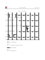
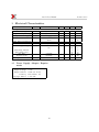
interX LED provides special on/off sequences to indicate different states of the interX CPU and GPS
module. Diagrams below show LED sequences and
their meaning
1s
ON
Low Battery State
LED Indicator
2s
ON
Constantly OFF
LLLLLLLLLLLLLLLLLLLLLLLLLLLLLLLLLLL
TTTTTTTTTTTTTTTTTTTTTTTTTTTTTTTTTTT
Low Battery State
1s
ON
GPS doing position fixes
In battery driven mode interX will monitor battery
charge capacity ( supplied voltage and current) If battery charge fails below threshold required for normal
operation interX will enter Low Battery State. In this
state only LED Indicator is functional and LED will
continuously blink to indicate Low Battery State (see
Section LED Indicator ). To return interX to normal
operation it’s batteries have to be exchanged.
0s
3s
LLLLLLLLLLL
TTTTTTTTTTTTTTTTTTTTTTTTTTTTTTTTTTT
0s
0s
2s
ON
Three Satellites Visible
DESCRIPTION
End terminal session and run application. After issuing this command interX will start normal operation and will not echo or respond terminal commands
2.4
ON
’g’ Command
SYNOPSIS
g
2.3
ON
3s
4s
9
ON
ON
1s
ON
ON
2s
ON
ON
3s
ON
4s