1
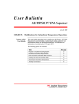
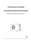
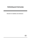
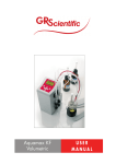
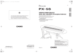
TABLE OF CONTENTS
EDITION 1
Section 1 - WARRANTY & SERVICE
1.1.
WARRANTY
2
1.2.
DAMAGED SHIPMENTS
2
1.3.
SERVICE
2
Section 2 - INTRODUCTION
2.1.
INTRODUCTION
2-3
Section 3 - GENERAL
3.1.
UNPACKING & INSTALLATION
4
3.2.
POWER SUPPLY
4
3.3.
PANEL
4
Section 4 - OPERATION
4.1.
INSTRUCTIONS
4.2.
SENSOR TEST
5-7
7
Section 5 - ROUTINE MAINTENANCE
5.1.
CLEANING
7
5.2.
STORAGE
7
5.3.
TROUBLE SHOOTING
7
Section 6 - SPECIFICATIONS
8
Section 7 - ACCESSORIES & ORDERING INFORMATION
8
INDEX
9
1
Section 1 - WARRANTY & SERVICE
1.1. WARRANTY
Univentor Ltd guarantees all components of the 2010 Scavenger Unit to be free from
defects of material and workmanship for a period of two years after initial purchase.
Univentor will repair or replace, at its discretion, all defective components during the
aforementioned warranty period.
For warranty service or repair, all Univentor’s products must be returned to Univentor or
to an authorised Univentor representative. The client is responsible for shipping charges
to Univentor.
The foregoing warranty shall not apply to defects resulting from improper or inadequate
maintenance by the client, unauthorised modification or misuse, operation outside of the
environmental specifications for the product, or improper site preparation or maintenance.
For any product expressly covered under this warranty, Univentor is liable only to the
extent of replacement or repair of the defective items. Univentor shall not be liable for any
personal injury, property damage, or consequential damages of any kind whatsoever. The
foregoing warranty is in lieu of all other warranties of merchant ability and fitness for a
particular purpose.
1.2. DAMAGED SHIPMENTS
Damage to any part of this instrument during shipping should be reported immediately
to Univentor or an authorised representative. You must retain the original packing box
and contents for inspection by the freight handler. Univentor will replace any new instrument
damaged in shipping with an identical product as soon as possible after the claim filing
date. Claims not filed within 30 days after the shipping date will be invalid. Do not return
damaged goods to Univentor without first contacting Customer Service.
1.3. SERVICE
Univentor has a skilled service staff available to solve any technical problem. For further
details contact Univentor or your Univentor representative. Following discussion of your
specific difficulties, an appropriate course of action will be described and the problem
resolved accordingly.
All correspondence and shipments should be sent to Univentor Ltd or your Univentor
representative.
Section 2 - INTRODUCTION
2.1. INTRODUCTION
The Univentor 2010 Scavenger is designed to collect and inactivate any surplus anaesthetic
gas that may be produced when using the Univentor 400 or 1200 units so as to provide
a safer working environment.
The gas is collected and passed through active coal contained in a cartridge. As the
cartridge approaches saturation successive alarms are triggered providing ample warning.
2
When using an induction chamber and a mask the Scavenger Gas Routing Switch,
8433020, should be used to enable correct and safe switching between the two.
Even though the 2010 Scavenger is extremely easy to use we recommend that you read
this User Manual before starting the instrument.
LIGHT A
RESET BUTTON
LIGHT B
FIGURE 2.1.1 .
RESET BUTTON
TEST ADAPTOR
AIR OUTLET
ON/OFF SWITCH
CARTRIDGE LEVER
OPEN
FIGURE 2.1. 2.
CLOSED
FIGURE 2.1. 3.
FIGURE 2.1.1/2/3 - The Univentor 2010 Scavenger Unit
3
Section 3 - GENERAL
3.1. UNPACKING AND INSTALLATION
Remove the instrument from the shipping container and inspect both the instrument and
the package for any signs of damage. If any damage is noted, contact the freight handler
immediately, see section 1.2.
Missing Items?
Your 2010 Scavenger Unit is delivered with:
a) 4 cartridges
b) 1 power supply
c) 1 mains lead
d) 1 user manual
If any items are missing contact your Univentor representative immediately.
3.2. POWER SUPPLY
MAINS - Use an earthed wall plug and the power supply, 7251001, supplied with the 2010
Scavenger Unit.
The power supply can automatically handle input voltage in the range from 100 V AC to
240 V AC 50 to 60 Hz.
3.3. PANEL
Reset audible alarm - silences and resets audible alarm.
Light A and B - indicates status of the 2010 Scavenger Unit:
Alarm one - concentration approximately 10 ppm
Alarm two - concentration approximately 50 ppm
Change cartridge - concentration approximately 100 ppm
Read the manual before use
A
Reset
audible
alarm
B
A
B
Flashing green Flashing green
Solid green
Solid green
Flashing red
Flashing red
Flashing red
Flashing red
Solid red
Solid red
ALARM/ACTION
Warming up
Normal running
Alarm one
Alarm two
Change cartridge
No gas flow
No cartridge
FIGURE 3.3. - The Control Panel
of the Univentor 2010 Scavenger Unit.
4
Section 4 - OPERATION
4.1. INSTRUCTIONS
Do not start the Univentor Anaesthetic Unit before the 2010 Scavenger is ready to
be used.
1. Connect tubing, keeping lengths as short as possible, according to your set up:
2010 SCAVENGER, UNIVENTOR ANAESTHESIA UNIT AND MASK
Inlet to Mask from
Anaesthesia Unit
Outlet from Mask to
Scavenger 2010 Inlet
2010 SCAVENGER, UNIVENTOR ANAESTHESIA UNIT AND INDUCTION CHAMBER
Outlet from Chamber
to Scavenger 2010 Inlet
Inlet to Chamber
from Anaesthesia Unit
.
2010 SCAVENGER, UNIVENTOR ANAESTHESIA UNIT, INDUCTION CHAMBER AND
MASK USING THE UNIVENTOR SCAVENGER SWITCH
Anaesthesia Unit Outlet
Scavenger 2010 Unit Intlet
Chamber Inlet
When pressed down
Anaesthesia/Scavenger
connected to Chamber
Mask Outlet
Mask Inlet
When pressed down
Anaesthesia/Scavenger
connected to Mask
Chamber Outlet
5
2. Connect the instrument to the power supply and earthed mains.
3. Write the date and the next cartridge number, eg.1/25, on the cartridge label so as to
keep count of the number of cartridges used. The sensor should be tested every 25
cartridges. Position cartridge lever in open position, fit the cartridge and close lever to
clamp.
4. Switch unit on.
Should the cartridge not be properly fitted light B turns red.
5. An automatic test of the alarm functions will be carried out:
a) light A flashes green
b) light A flashes red
c) light B flashes green
d) light B flashes red
e) audible alarm sounds 3 times
6. Light A and light B flashing green whilst warming up – approximately 5 to 15 minutes
depending on environmental conditions.
7. Once the lights are solid green the unit is ready.
8. Each cartridge can absorb 40-50mL anaesthetic and 3 warnings are given prior to
saturation:
Alarm one - concentration approximately 10 ppm - light A flashes red and audible alarm
is activated. Cartridge may be changed.
Press RESET button to silence audible alarm.
Alarm two - concentration approximately 50 ppm - light B flashes red and audible alarm
is activated/reactivated. Cartridge may be changed.
Press RESET button to silence audible alarm.
Change cartridge - concentration approximately 100 ppm - light A and light B flash red
and audible alarm is activated/reactivated. Cartridge must be changed.
Press RESET button to silence audible alarm.
NOTE: the weight of the cartridge increases with 14.5g with every 10mL anaesthetic
absorbed.
9. Stop the delivery of anaesthetic, remove cartridge and fit a new, dated and numbered,
cartridge.
10. Delivery of anaesthetic may be started when light A and light B flash green.
6
4.2. SENSOR TEST
To ensure that the anaesthetic sensor is working properly we recommend that the following
test is carried out with every 25 cartridges:
1. Fit a cartridge that has not approached saturation and switch the unit on.
2. Set the Anaesthetic Unit:
Air flow - 900mL/min
Concentration - 0.5%
3. When light A and light B of the 2010 are solid green replace the cartridge with the test
adaptor. See figure 2.1.2.
4. Connect the adaptor with the gas outlet of the Anaesthetic Unit using 6/4 PVC tubing
shorter than 0.5m.
5. Connect tubing to the air outlet of the 2010 to remove the anaesthetic gas from the
working area.
6. Switch on the Anaesthetic Unit.
7. Light A and light B of the 2010 should flash red within 10 minutes.
8. As soon as red lights go on remove the adaptor and refit the cartridge.
NOTE: Should the lights not turn red contact Univentor or your Univentor representative.
Do NOT use the instrument.
Section 5 - ROUTINE MAINTENANCE
5.1. CLEANING THE INSTRUMENT
Keep your Univentor 2010 Scavenger Unit clean. Wipe off any spillage using a soft cloth
with mild detergent. Do not use alcohol or any other solvent.
5.2. STORAGE
If the Univentor 2010 Scavenger Unit is not to be used for a significant length of time, it
is recommended to clean the instrument and store it safely.
5.3. TROUBLE SHOOTING
1. Light A is solid red – no gas flow:
• Check tubing
• Check vacuum pump for audible output
2. Light B is solid red – no cartridge:
• Check cartridge position
3. No alarms:
• Run sensor test
7
Section 6 - SPECIFICATIONS
Power
POWER SUPPLY: 100 - 240 V AC 50 - 60 Hz.
Dimensions:
90(W) x 155(D) x 230(H) mm.
Weight:
1.52 kg
Shipping weight:
3.5 kg
Vacuum pump:
minimum 1,6 litre /min when connected to a induction
chamber or mask.
Active coal cartridge:
diameter 62 mm hight 162 mm
absorbs 40-50mL anaesthetic
increases with 14.5g for every 10mL
of anaesthetic absorbed.
Alarm concentrations:
Level 1 - concentration 10 ppm
Level 2 - concentration 50 ppm
Level 3 - concentration 100 ppm.
We reserve the right to improve our instruments without notification.
Section 7
ACCESSORIES & REPLACEMENT PARTS
ORDERING INFORMATION
CAT. No.
DESCRIPTION
8338001
Univentor 2010 Scavenger
8438025
Active Coal Cartridge – pkt of 4
8438050
Sensor Test Adaptor
8433020
Univentor Scavenger Routing Switch
8329001
Induction Chamber 0.8l.
8329002
Induction Chamber 1.4l.
7251001
Power Supply
8
INDEX
ACCESSORIES.................................................................................................8
ALARMS..........................................................................................................6-7
CLEANING THE INSTRUMENT................................................................................7
CARTRIDGE - fitting and specifications......................................................6-8
DAMAGED SHIPMENTS..................................................................................2
INSTRUCTIONS..............................................................................................5-6
INTRODUCTION..............................................................................................2-3
MAINTENANCE AND STORAGE.......................................................................7
OPERATING INSTRUCTIONS........................................................................5-6
PACKING LIST.......................................................................................................3
PANEL........................................................................................................................4
POWER SUPPLY...................................................................................................4
SENSOR TEST………………………….....………………………………………….....7
SERVICE.......................................................................................................2
SPECIFICATIONS.........................................................................................8
TROUBLE SHOOTING................................................................................7
TUBING.......................................................................................................5
UNPACKING AND INSTALLATION..............................................................4
WARRANTY.......................................................................................................2
9
BLB029, Bulebel Industrial Estate, Zejtun ZTN 3000, Malta.
Tel: (+356) 21 895824. Fax: (+356) 21 895835.
E-mail: [email protected]
Homepage: http://www.univentor.com