1
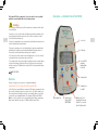
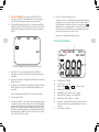
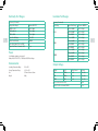
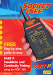
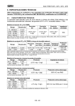
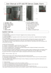
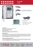
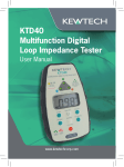
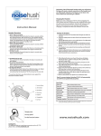
KTD30
Digital Insulation and
Continuity Tester
User Manual
www.kewtechcorp.com
1
The Kewtech KTD30 Loop Impedence Tester is designed for use by suitably
qualified personnel familiar with electrical supply systems.
Operation – a Detailed View of the KTD30
Caution
Before using your KTD30 please read these instructions; in particular note the safety
issues that follow:
2
Your tester is for use on dead circuits only. Although your Kewtech instrument is fully
protected against accidental connection to a live circuit it is essential to check the
circuit is dead before working on it.
1 Live Circuit
Your tester is equipped with a very convenient auto test (hands free) feature but do not
touch the lead tips when using this feature.
There may be capacitance on the circuit being tested (a longer than normal test time
will indicate this condition). Your tester will automatically discharge this but do not
disconnect the test leads until this auto discharge has completed.
2 LCD Display
On the subject of test leads, always check for damaged leads or croc clips - Kewtech
replacement lead sets are inexpensive and easy to obtain.
3 Power ON/OFF
(including
Intelligent Auto
Power Off)
The continuity circuit is fuse protected against accidental connection to mains (unlikely
as there will be a warning to indicate a live circuit) - if this fuse does blow replace it
with the correct type F 500mA fast blow ceramic 500V. It is located inside the battery
compartment.
BS EN 61010-1
6 Continuity Test
Batteries
Because of storage issues your tester is not supplied with batteries.
ALWAYS REMOVE THE TEST LEADS BEFORE REPLACING BATTERIES.
7 Continuity Test
Lead Null
Just 4 AA cells are required (alkaline recommended). The battery compartment is at the
the back of the instrument, remove the screw (do not lose it) – slide the battery cover
off and carefully insert the batteries observing correct polarity. Replace cover and fix
screw back in. 4 good quality AA alkaline cells should give 5000 tests at 500V DC.
Note: Access to the protective fuse is also gained through the battery compartment.
Always replace with the correct type – F 500mA Fast Blow Ceramic 500V.
4 Insulation Test
5 Insulation Test
Voltage 250V
500V 1000V
8 Briefly Pust to Test
(Instant) plus Push and
Hold for 2 seconds for
Auto Test (Hands Free)
3
1
2
LIVE CIRCUIT WARNING If this is alight – DO NOT PROCEED you are
connected to a live circuit. This useful indicator will also show if a (capacitive)
circuit under test is fully discharged before disconnecting any test leads.
1 LIVE CIRC UIT WARNING If this is alight – DO NOT PROCEED you are
connected to a live circuit. This useful indicator will also show if a (capacitive)
Display.
When power up (Power ON/OFF) is selected your Kewtech
circuit under test is fully discharged before disconnecting any test leads.
The Push To Test Button performs two functions:
A brief push (less than one second) initiates the test and automatically captures the
result (which stays on screen until the next test, Power OFF or Mode change). For
Auto Test the button is held down for longer than 2 seconds at which point
is
displayed in the LCD – you now have Hands Free – when the probes are touched
onto any two test points your KTD30 will carry out an automatic test and capture
the result for as long as the probes are held in contact.
A brief push on the Test button unlocks Hands Free mode.
LCD
KTD30
will default to symbols CERT, INS, 500V this means it is ready to perform a 500V
2 LCD Display. When power up (Power ON/OFF) is selected your Socket &
insulation
Certification
and
it will
thisthis
test
when
briefly press
Seetest
PDITin360
will default tomode
symbols
CERT,
INS,do
500V
means
it isyou
ready
button 8.
to perform a 500V insulation test in Certification mode and it will do this test
when you briefly hit button 9.
CERT
4
8
INS
500V
5
Overview
of the
Display
Overview
of the
Display
I
MΩ
D
H
E
CERT CONT INS
500V
NUL
250V 1000V
F
C
3 Power ON/OFF – Pressing and releasing this button turns the PDIT 360 on
holding down for longer than 2 seconds turns the unit off (plus Auto Power
MΩ
B
is how
display will
will look
youyou
first first
powerpower
up the instrument.
This This
is how
thethedisplay
lookwhen
when
up the instrument.
–
3
Power ON/OFF
– Pressing and releasing this button turns the KTD30 on –
Off is incorporated).
holding
down
for selects
longerInsulation
than 2 seconds
turns
unit
(plus to
Auto Power Off is
4 This
button
Testing Mode
(yourthe
PDIT
360off
defaults
incorporated).
Insulation Test 500V DC on Power On).
4
This button
selects
Insulation
Testing
(your
KTD30
defaults
circuits
500V DC
(default) for
circuitsMode
up to and
including
500V
with the to Insulation Test
500V DC
on Power
exception
of theOn).
above systems
A
A Fuse
BrokenDO
DO NOT
Fuse
Broken
NOTPROCEED
PROCEED
This allows
selection of insulation test voltage 250V DC for SELV and PELV circuits
6 Selects Continuity Test Mode.
500V DC (default) for circuits up to and including 500V and 1000V for circuits
abouve 500V
B
B Greater
> GreaterThan
Than // < < Less
> LessThan
Than
C
C Battery Condition
Battery
Condition
D
TestMode – CERT – Certification
E
Measuring
Mode – INS – Insulation or CONT – Continuity
F Insulation DC Volts Test Pressure – 250 – 500V DC
5
G
5 This allows selection of insulation test voltage 250V DC for SELV and PELV
(SELV = Separated Extra-Low Voltage. PELV = Protective Extra-Low Voltage).
(SELV = Separated Extra-Low Voltage. PELV = Protective Extra-Low Voltage).
6
Selects Continuity Test Mode.
7
Continuity Test Lead NULL – In order to give accurate continuity resistance results
your tester will record the resistance of the test leads – store it and automatically
subtract the stored value from any continuity measurement being made. To NULL
the leads hold the test lead tips together very firmly with one hand and press the
NULL Button – the result will be displayed – continuity testing will then subtract this
stored value whenever Test Button 8 is pressed – the value is reset to zero after
Power OFF (or Auto Power OFF) is selected.
4
A
F
good.
= =good. = 1/2. Flashing = replace.
= 1/2. Flashing = replace.
D TestMode – CERT – Certification
E Measuring Mode
– INS – Insulation or CONT
– Continuity
Insulation
DC Units
Volts–Test
500-1000V DC
G Measuring
M –Voltage
Insulation– –250– –
Continuity
G
Measuring
Units
– MΩ – only)
Insulation
– stores
Ω – Continuity
H Nul Function
– (Continuity
Nuls and
Ohms value of the test leads
H
Null Function – (Continuity only) Nulls and stores Ohms value of the test I AutoTest (Hands Free) Selected
leads
for the testing session you are in (automatically resets to zero on switch off)
I
AutoTest (Hands Free) Selected
for the testing session you are in (automatically resets to zero on switch off)
6
Continuity Test Ranges
Insulation Test Ranges
Accuracy (Cert mode)
6
Accuracy (Cert mode)
Ranges (Auto Range)
Tolerance (@ 20°C)
0.00 to 9.99Ω
±3% ±2 digits
10.0 to 99.9Ω
±3% ±2 digits
100 to 999Ω
Ranges (Auto Range)
Tolerance (@200C)
0.01 to 9.99MΩ
±3% ±1 digit
10.0 to 99.9MΩ
±3% ±1 digit
±3% ±2 digits
100 to 199MΩ
±6% ±1 digit
Open Circuit Voltage
>4V, <10V
0.01 to 9.99MΩ
±3% ±1 digit
Short Circuit Current
>200mA
10.0 to 99.9MΩ
±3% ±1 digit
Zero offset Adjust (Test Lead Null)
2Ω
100 to 199MΩ
±3% ±1 digit
Typical Test Time (Cert mode) (2Ω)
<2 sec
200 to 499MΩ
±6% ±1 digit
0.01 to 9.99MΩ
±3% ±1 digit
10.0 to 99.9MΩ
±3% ±1 digit
100 to 399MΩ
±3% ±1 digit
400 to 999MΩ
±6% ±1 digit
Power
4 × AA alkaline batteries (not included)
Battery Life (BS EN 61557) > 5000 tests @ 500V test voltage
Environmental
Test Voltage
250V
500V
1000V
Output Voltage
Operating Temperature Range
0°C to 40°C
Storage Temperature Range
–10°C to 60°C
Voltage
Load
Output Current
Tolerance
Size
157mm × 89mm × 39mm
250
250kΩ
1 mA
–0% +20%
Weight
400g
500
500kΩ
1 mA
–0% +20%
1000
1MΩ
1 mA
–0% +20%
Short circuit current (in to 2kΩ)
<2mA
Typical Test Time (cert mode) (10MΩ)
<2 sec
7
8
Kewtech Corporation Limited
Midas House, Unit 2b, Stones Courtyard, High Street, Chesham, Bucks HP5 1DE
T: 01494 792 212
F: 01494 791 826
E: [email protected]
www.kewtechcorp.com