1
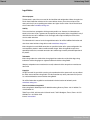
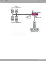
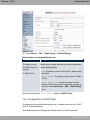
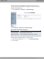
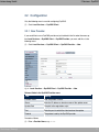
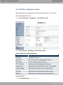
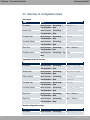
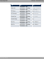
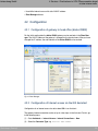
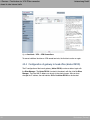
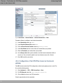
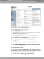
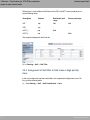
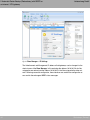
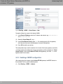
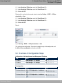
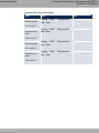
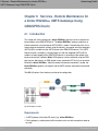
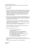
Manual
bintec elmeg GmbH
Manual
Workshops (Excerpt)
Services Workshops
Copyright© Version 10/2013 bintec elmeg GmbH
Workshops (Excerpt)
1
Manual
bintec elmeg GmbH
Legal Notice
Aim and purpose
This document is part of the user manual for the installation and configuration of bintec elmeg devices.
For the latest information and notes on the current software release, please also read our release
notes, particularly if you are updating your software to a higher release version. You will find the latest
release notes under www.bintec-elmeg.com .
Liability
This manual has been put together with the greatest possible care. However, the information contained in this manual is not a guarantee of the properties of your product. bintec elmeg GmbH is only liable within the terms of its conditions of sale and supply and accepts no liability for technical inaccuracies and/or omissions.
The information in this manual can be changed without notice. You will find additional information and
also release notes for bintec elmeg devices under www.bintec-elmeg.com .
bintec elmeg devices make WAN connections as a possible function of the system configuration. You
must monitor the product in order to avoid unwanted charges. bintec elmeg GmbH accepts no responsibility for data loss, unwanted connection costs and damage caused by unintended operation of
the product.
Trademarks
bintec elmeg trademarks and the bintec elmeg logo, bintec trademarks and the bintec logo, elmeg
trademarks and the elmeg logo are registered trademarks of bintec elmeg GmbH.
Company and product names mentioned are usually trademarks of the companies or manufacturers
concerned.
Copyright
All rights reserved. No part of this manual may be reproduced or further processed in any way without
the written consent of bintec elmeg GmbH. The documentation may not be processed and, in particular, translated without the consent of bintec elmeg GmbH.
You will find information on guidelines and standards in the declarations of conformity under
www.bintec-elmeg.com .
How to reach bintec elmeg GmbH
bintec elmeg GmbH, Südwestpark 94, D-90449 Nuremberg, Germany, Phone: +49 911 9673 0, Fax:
+49 911 688 07 25
Teldat France S.A.S., 6/8 Avenue de la Grande Lande, F-33174 Gradignan, France, Phone: +33 5 57
35 63 00, Fax: +33 5 56 89 14 05
Internet: www.teldat.fr
2
Workshops (Excerpt)
Table of Contents
bintec elmeg GmbH
Table of Contents
Workshops (Excerpt)
Chapter 1
Services - DHCP . . . . . . . . . . . . . . . . . . . . . . . . 1
1.1
Introduction . . . . . . . . . . . . . . . . . . . . . . . . . . . .
1
1.2
Configuration
. . . . . . . . . . . . . . . . . . . . . . . . . . .
3
1.2.1
Configuring as a DHCP server . . . . . . . . . . . . . . . . . . . .
3
1.2.2
Configuration as DHCP Client . . . . . . . . . . . . . . . . . . . .
6
1.2.3
Configuring a DHCP relay server . . . . . . . . . . . . . . . . . . .
7
1.3
Overview of configuration steps
9
Chapter 2
Services - DynDNS . . . . . . . . . . . . . . . . . . . . . . 10
2.1
Introduction . . . . . . . . . . . . . . . . . . . . . . . . . . .
10
2.2
Configuration. . . . . . . . . . . . . . . . . . . . . . . . . . .
11
2.2.1
New Provider . . . . . . . . . . . . . . . . . . . . . . . . . .
11
2.2.2
Configuring DynDNS . . . . . . . . . . . . . . . . . . . . . . .
12
2.2.3
NAT entries for administration with the GUI . . . . . . . . . . . . .
13
2.3
Result . . . . . . . . . . . . . . . . . . . . . . . . . . . . . .
14
2.4
Checking the connection. . . . . . . . . . . . . . . . . . . . . .
14
2.5
Overview of configuration steps. . . . . . . . . . . . . . . . . . .
14
Chapter 3
Services - Time-controlled Tasks . . . . . . . . . . . . . . 16
3.1
Introduction . . . . . . . . . . . . . . . . . . . . . . . . . . .
16
3.2
Configuration. . . . . . . . . . . . . . . . . . . . . . . . . . .
17
3.2.1
Daily reboot . . . . . . . . . . . . . . . . . . . . . . . . . . .
17
3.2.2
Suspending the WLAN interface . . . . . . . . . . . . . . . . . .
18
3.2.3
Monthly configuration backup . . . . . . . . . . . . . . . . . . .
20
3.3
Overview of configuration steps. . . . . . . . . . . . . . . . . . .
21
. . . . . . . . . . . . . . . . . . .
i
Table of Contents
ii
bintec elmeg GmbH
Chapter 4
Services - Prioritisation of a VPN IPSec connection ahead of
other Internet traffic . . . . . . . . . . . . . . . . . . . . . 24
4.1
Introduction . . . . . . . . . . . . . . . . . . . . . . . . . . .
24
4.2
Configuration
. . . . . . . . . . . . . . . . . . . . . . . . . .
25
4.2.1
Configuration of gateway in head office (bintec R3002) . . . . . . . .
25
4.2.2
Configuration of Internet access via the GUI Assistant
25
4.2.3
Configuration of the VPN IPSec access of the first branch via the GUI Assistant
. . . . . . . . . . . . . . . . . . . . . . . . . . . . . . . . . 26
4.2.4
Configuration of gateway in head office (bintec RS120) . . . . . . . .
28
4.2.5
Configuration of Internet access via the GUI Assistant
. . . . . . . .
29
4.2.6
Configuration of the VPN IPSec tunnel on the branch gateway . . . . .
30
4.3
Testing the VPN connection . . . . . . . . . . . . . . . . . . . .
32
4.4
Prioritisation of the VPN tunnel on the branch gateway ahead of other Internet
traffic . . . . . . . . . . . . . . . . . . . . . . . . . . . . . . 33
4.4.1
Creation of QoS filters . . . . . . . . . . . . . . . . . . . . . . .
33
4.4.2
Assignment of QoS filter to QoS class or high priority class
. . . . . .
34
4.4.3
Enabling QoS on the WAN interface
. . . . . . . . . . . . . . . .
36
4.4.4
QoS Monitoring
. . . . . . . . . . . . . . . . . . . . . . . . .
37
4.5
Overview of Configuration Steps . . . . . . . . . . . . . . . . . .
37
Chapter 5
Automatic Router Backup (Redundancy) with BRRP for an Internet / VPN gateway . . . . . . . . . . . . . . . . . . . . 42
5.1
Introduction . . . . . . . . . . . . . . . . . . . . . . . . . . .
42
5.2
Configuration
. . . . . . . . . . . . . . . . . . . . . . . . . .
43
5.2.1
Configuration of the Advertisement and Management IP address . . . .
43
5.2.2
Configuration of the virtual router . . . . . . . . . . . . . . . . . .
46
5.2.3
Enabling of BRRP configuration . . . . . . . . . . . . . . . . . .
48
5.2.4
Synchronisation of the virtual routers . . . . . . . . . . . . . . . .
50
5.3
Overview of Configuration Steps . . . . . . . . . . . . . . . . . .
51
. . . . . . . .
Workshops (Excerpt)
Table of Contents
bintec elmeg GmbH
Workshops (Excerpt)
Chapter 6
Services - Remote Maintenance for a bintec RS232bu+ UMTS
Gateways Using GSM/GPRS Dial-In . . . . . . . . . . . . 54
6.1
Introduction . . . . . . . . . . . . . . . . . . . . . . . . . . .
54
6.2
Configuration
55
6.3
Test the UMTS fallback with an incoming voice connection
. . . . . .
57
6.4
Dial-in by ISDN login from a different bintec ISDN gateway
. . . . . .
58
6.5
Overview of Configuration Steps . . . . . . . . . . . . . . . . . .
59
. . . . . . . . . . . . . . . . . . . . . . . . . .
iii
Table of Contents
iv
bintec elmeg GmbH
Workshops (Excerpt)
1 Services - DHCP
bintec elmeg GmbH
Chapter 1 Services - DHCP
1.1 Introduction
The configuration of Dynamic Host Configuration Protocol (DHCP) is described in the following chapters.
You can use your device as a DHCP server, DHCP client or DHCP relay agent.
Configuration in this scenario is carried out using the GUI (Graphical User Interface).
Fig. 2: Example scenario as a DHCP server
Workshops (Excerpt)
1
1 Services - DHCP
bintec elmeg GmbH
Fig. 3: Example scenario as a DHCP client
2
Workshops (Excerpt)
1 Services - DHCP
bintec elmeg GmbH
Fig. 4: Example scenario as a DHCP relay server
Requirements
The following are required for the configuration:
• Boot image from version 7.10.1
• An optional DHCP server
1.2 Configuration
1.2.1 Configuring as a DHCP server
If you wish to assign an IP address to the client computers in the network dynamically
through your gateway, you must configure it as a DHCP server. To activate your device as
a DHCP server, you must first define IP address pools from which the IP addresses are
distributed to the requesting clients.
For this, go to the following menu:
Workshops (Excerpt)
3
1 Services - DHCP
bintec elmeg GmbH
(1)
Go to Local Services -> DHCP Server -> DHCP Pool -> New.
Fig. 5: Local Services -> DHCP Server -> DHCP Pool -> New
Relevant fields in menu DHCP Pool
Field
Meaning
Interface
Here you select the interface via which the IP addresses are to
be distributed by DHCP.
IP Address Range
Enter the first and last IP addresses to be assigned by DHCP.
Pool Usage
Specify whether the IP pool is used for DHCP requests in the
same subnet or for DHCP requests that have been forwarded to
your device from another subnet. In this case it is possible to
define IP addresses from another network.
Additional configuration parameters can be found under Advanced Settings:
Relevant fields in the menu Advanced Settings
Field
Meaning
Gateway
Here you can specify whether the gateway is to be used as a
default gateway or can enter a gateway IP address if the gateway is not to be used as a default gateway.
Lease Time
The length of time in minutes that the client can keep the IP address.
Proceed as follows to configure your gateway as a DHCP server:
4
(1)
Select your LAN interface for Interface, e.g. .
(2)
Enter the first and last IP addresses from your LAN under IP Range, e.g.
and .
Workshops (Excerpt)
1 Services - DHCP
bintec elmeg GmbH
(3)
In Pool Use, select .
(4)
Under Gateway select .
(5)
Leave the Lease Time set to .
(6)
Confirm with OK.
The GUI offers a facility for checking whether or not IP addresses are assigned to clients
from the DHCP pool and if so which addresses are involved. To check who has received
an IP address, select the following menu options:
(1)
Go to Local Services -> DHCP Server -> IP/MAC Binding.
Fig. 6: Local Services -> DHCP Server ->IP/MAC Binding
Here you obtain all the important information concerning the issue of IP addresses from the
DHCP pool.
The gateway assigns an IP address to the client as the DHCP server and not only sends
the IP address of the gateway to the client, but also the IP address of the DNS server.
Use the following menu item to determine which IP address the gateway sends to the client
as the DNS server address:
(1)
Workshops (Excerpt)
Go to Local Services -> DNS -> Global Settings -> Advanced Settings.
5
1 Services - DHCP
bintec elmeg GmbH
Fig. 7: Local Services -> DNS -> Global Settings -> Advanced Settings
Relevant fields in the Advanced Settings menu
Selection
Meaning
IP Address to use for
DNS/WINS Server Assignment:
Select the most suitable method for your network environment
from the following options:
As DHCP Server
• : The gateway issues no DNS server IP addresses with
this setting.
• : The gateway assigns its own IP address
as DNS.
•
! "# #$: The gateway assigns the IP addresses as DNS, which you have configured or assigned dynamically in the Local Services -> DNS -> Global Settings
menu.
You can normally keep the % setting for As DHCP Server.
1.2.2 Configuration as DHCP Client
The gateway has the possibility of obtaining its own IP address dynamically from a DHCP
server at an Ethernet interface.
Go to the following menu to configure your Ethernet interface to DHCP client mode:
6
Workshops (Excerpt)
1 Services - DHCP
bintec elmeg GmbH
(1)
Go to LAN -> IP Configuration -> Interfaces -> <en1-4> ->
.
Fig. 8: LAN -> IP Configuration -> Interfaces -><en1-4> ->
Relevant fields in the Interfaces menu
Field
Meaning
Address mode
Select DHCP to obtain an IP address as client via the interface.
Additional configuration parameters can be found under Advanced Settings.
Relevant fields in the menu Advanced Settings
Field
Meaning
DHCP MAC Address
If you expect an IP address from a certain DHCP server, you
can enter its MAC address here.
Proceed as follows to configure the gateway as a DHCP client:
(1)
Set Address Mode to "&'.
(2)
Confirm with OK.
Now you should receive all the important configuration parameters like IP address, gateway and DNS from your DHCP server.
1.2.3 Configuring a DHCP relay server
If the gateway for the local network does not distribute any IP addresses to the clients by
DHCP, it can still forward the DHCP requests on behalf of the local network to a remote
DHCP server.
Workshops (Excerpt)
7
1 Services - DHCP
bintec elmeg GmbH
The DHCP server then assigns the gateway an IP address from its pool, which in turn
sends this to the client in the local network. The settings for a DHCP relay server can be
modified in the following submenu:
(1)
Go to Local Services -> DHCP Server -> DHCP Relay Settings.
Fig. 9: Local Services -> DHCP Server -> DHCP Relay Settings
Relevant fields in the DHCP Relay Settings menu
Field
Meaning
Primary DHCP Server
Enter the IP address of the first server.
Secondary DHCP Server
Enter the IP address of the second server, if one exists.
Proceed as follows to configure the gateway as a DHCP relay agent:
8
(1)
Enter the server IP address, e.g. , for the Primary DHCP Server.
(2)
Confirm with OK.
Workshops (Excerpt)
1 Services - DHCP
bintec elmeg GmbH
1.3 Overview of configuration steps
DHCP Server
Field
Menu
Value
Interface
Local Services -> DHCP Server ->
DHCP Pool -> New
e.g. IP Address Range
Local Services -> DHCP Server ->
DHCP Pool -> New
e.g. and
Pool Usage
Local Services -> DHCP Server ->
DHCP Pool -> New
Gateway
Local Services -> DHCP Server ->
DHCP Pool -> New -> Advanced
Settings
( Lease Time
Local Services -> DHCP Server ->
DHCP Pool -> New -> Advanced
Settings
e.g. IP Address to use for
DNS/WINS Server Assignment: As DHCP
Server
Local Services -> DNS -> Global
Settings -> Advanced Settings
e.g. Field
Menu
Value
Address mode
LAN -> IP Configuration -> Interfaces -> <en1-4> ->
"&'
DHCP MAC Address
(optional)
LAN -> IP Configuration -> InterMAC address for a spefaces -> <en1-4> ->
-> Advanced cific DHCP server
DHCP Client
Configurations
DHCP Relay Server
Workshops (Excerpt)
Field
Menu
Value
Primary DHCP Server
Local Services -> DHCP Server ->
DHCP Relay Settings
e.g. Secondary DHCP Server (optional)
Local Services -> DHCP Server ->
DHCP Relay Settings
if one exists
9
2 Services - DynDNS
bintec elmeg GmbH
Chapter 2 Services - DynDNS
2.1 Introduction
The following chapters describe the configuration of DynDNS.
You create an entry for the DynDNS provider and configure your DynDNS name
!$$)*. You then create NAT enables in order to administrate the gateway
over the Internet using http.
Configuration in this scenario is carried out using the GUI (Graphical User Interface).
Fig. 10: Example scenario DynDNS
Requirements
The following are required for the configuration:
• Basic configuration of the gateway
• Boot image from version 7.10.1
• Configuration requires a working Internet access
• Successful registration with the DynDNS provider www.no-ip.com
10
Workshops (Excerpt)
2 Services - DynDNS
bintec elmeg GmbH
2.2 Configuration
Only the following menu is used for configuring DynDNS:
(1)
Go to Local Services -> DynDNS Client.
2.2.1 New Provider
If you would like to use a DynDNS provider not yet included in the list under the menu option Local Services -> DynDNS Client -> DynDNS Provider, you must add this via the
following menu:
(1)
Go to Local Services -> DynDNS Client -> DynDNS Provider -> New.
Fig. 11: Local Services -> DynDNS Client -> DynDNS Provider -> New
Relevant fields in the DynDNS Provider menu
Field
Meaning
Provider Name
Give the provider a name.
Server
Enter the IP address or domain names of the update server.
Update Path
The path to the registration script.
Port
Enter the port via which the client receives the update.
Protocol
The protocol used by the DynDNS provider.
Proceed as follows:
(1)
Workshops (Excerpt)
Enter a Provider Name, e.g. .
11
2 Services - DynDNS
bintec elmeg GmbH
(2)
Enter )$)* for Server.
(3)
Enter +$+) under Update Path.
(4)
Leave the Port set to .
(5)
Select ""# for Protocol.
(6)
Confirm with OK.
2.2.2 Configuring DynDNS
Create an entry in the gateway for your registered DynDNS name. For this, go to the following menu:
(1)
Go to Local Services -> DynDNS Client -> DynDNS Update -> New.
Fig. 12: Local Services -> DynDNS Client -> DynDNS Update -> New
Relevant fields in the DynDNS Update menu
Field
Meaning
Hostname
Enter the complete host name you have registered.
Interface
Select the internet interface.
User Name
Enter your user name.
Password
Enter your password.
Provider
Select your DynDNS provider.
Enable update
Activate or deactivate the entry.
Proceed as follows:
(1)
12
Enter Host Name, e.g. !$$)*.
Workshops (Excerpt)
2 Services - DynDNS
bintec elmeg GmbH
(2)
Select Interface, e.g. .
(3)
Enter User Name, e.g. *,*$.
(4)
Under Password enter for example.
(5)
The Provider is .
(6)
Activate Enable Update.
(7)
Confirm with OK.
2.2.3 NAT entries for administration with the GUI
You should be able to administrate your gateway using HTTP over the Internet. Go to the
following menu to configure the corresponding NAT enable:
(1)
Go to Networking -> NAT -> NAT Configuration -> New.
Fig. 13: Networking -> NAT -> NAT Configuration -> New
Relevant fields in the Portforwarding menu
Field
Meaning
Interface
This is the connection that the NAT enable should receive.
Service
This is the service you reach from outside the gateway.
Source IP Address/Netmask
Enter the external IP address of the gateway here.
New Destination Port
The IP address to which you wish to be forwarded when you
reach the gateway.
Proceed as follows to configure the NAT enable:
(1)
Workshops (Excerpt)
Set the Interface to -%./0(0/ for example.
13
2 Services - DynDNS
bintec elmeg GmbH
(2)
Configure the Service to 1).
(3)
Under Source IP Address/Netmask select %.
(4)
Leave other settings unchanged and confirm your entries with OK.
2.3 Result
You have entered the DynDNS provider and your registered a DynDNS name in the
gateway. The bintec gateway can now also be administrated over the Internet.
2.4 Checking the connection
Go to the following menu to check that the current IP address is successfully registered
with the DynDNS provider:
(1)
Go to Local Services -> DynDNS Client.
The Status field of this menu must be set to ).
If you wish to administrate the bintec gateway over the Internet, enter the following in the
Browser on a remote computer:
You should then receive the login of the GUI for the bintec gateway.
2.5 Overview of configuration steps
Creating new providers
Field
Menu
Value
Provider Name
Local Services -> DynDNS Client -> e.g. DynDNS Providers -> New
Server
Local Services -> DynDNS Client -> )
DynDNS Providers -> New
$)*
Update Path
Local Services -> DynDNS Client -> +$+)
DynDNS Providers -> New
Port
Local Services -> DynDNS Client -> DynDNS Providers -> New
Protocol
Local Services -> DynDNS Client -> ""#
DynDNS Providers -> New
Configuring DynDNS
14
Workshops (Excerpt)
2 Services - DynDNS
bintec elmeg GmbH
Field
Menu
Value
Hostname
Local Services -> DynDNS Client -> e.g.
DynDNS Update -> New
!$$)*
Interface
Local Services -> DynDNS Client -> e.g. DynDNS Update -> New
User Name
Local Services -> DynDNS Client -> e.g. *,*$
DynDNS Update -> New
Password
Local Services -> DynDNS Client -> e.g. DynDNS Update -> New
Provider
Local Services -> DynDNS Client -> DynDNS Update -> New
Enable update
Local Services -> DynDNS Client -> %2$3$
DynDNS Update -> New
NAT entries
Workshops (Excerpt)
Field
Menu
Value
Interface
Networking -> NAT -> NAT Configuration -> New
e.g. -%./0(0/
Service
Networking -> NAT -> NAT Configuration -> New
1)
Source IP Address/Netmask
Networking -> NAT -> NAT Configuration -> New
%
15
3 Services - Time-controlled Tasks
bintec elmeg GmbH
Chapter 3 Services - Time-controlled Tasks
3.1 Introduction
The following chapters describe the configuration of time-controlled tasks.
• You want to reboot your gateway automatically overnight.
• The WLAN interface is to be suspended at the weekend.
• In addition, the configuration is to be backed up automatically once a month on a TFTP
server.
Configuration in this scenario is carried out using the GUI (Graphical User Interface).
Fig. 14: Sample scenario time-controlled tasks
Requirements
The following are required for the configuration:
• Basic configuration of the gateway.
• Boot image from version 7.8.2
16
Workshops (Excerpt)
3 Services - Time-controlled Tasks
bintec elmeg GmbH
3.2 Configuration
Only the following menu is used for configuring time-controlled tasks:
(1)
Go to Local Services -> Scheduling -> Time Schedule.
3.2.1 Daily reboot
Go to the following menu to configure the gateway so that the router executes a certain action at a certain time:
(1)
Go to Local Services -> Scheduling -> Time Schedule-> New.
Fig. 15: Local Services -> Scheduling-> Time Schedule-> New
Relevant fields in the Time Schedule menu
Field
Meaning
Description
Give the entry a name.
Select action
Select the action you want the gateway to execute.
Condition Type
Select the frequency with which the action is to be executed.
Condition Settings
Select the day on which the action is to be executed.
Start Time
Specify the time at which the action is to be executed.
Proceed as follows:
(1)
Workshops (Excerpt)
Under Description enter (!.
17
3 Services - Time-controlled Tasks
(2)
Under Select Action select (! "3$.
(3)
Select the Condition Type $.
(4)
In the Condition Settings field select "$.
(5)
Enter the time under Start Time: Hour Minute .
(6)
Confirm with OK.
bintec elmeg GmbH
Note
The gateway checks the configured events only every 300 seconds. To reduce the
time to every second, for example, go to the menu Local Services -> Scheduling ->
Options and enter a Schedule Interval, e.g. 4. Note that checking every second may
overload the gateway.
Fig. 16: Local Services -> Scheduling-> Options
3.2.2 Suspending the WLAN interface
Generate another entry to disable the WLAN interface on Saturday and Sunday.
Go to the following menu for this:
(1)
18
Go to Local Services -> Scheduling -> Time Schedule-> New.
Workshops (Excerpt)
3 Services - Time-controlled Tasks
bintec elmeg GmbH
Fig. 17: Local Services -> Scheduling-> Time Schedule-> New
Relevant fields in the Time Schedule menu
Field
Meaning
Description
Give the entry a name.
Select action
Select the action you want the gateway to execute.
Select interface
Select the interface you wish to enable or suspend.
Condition Type
Select the frequency with which the action is to be executed.
Condition Settings
Select the day on which the action is to be executed.
Start Time
Specify the time at which the action is to be executed.
Stop Time
Specify the time at which the action is to be terminated.
Proceed as follows:
Workshops (Excerpt)
(1)
Under Description enter -$ %.
(2)
Under Select Action select "$3 -%.
(3)
Under Select Interface choose 522637 for example.
(4)
Select the Condition Type $.
(5)
In the Condition Settings field, select # #.
(6)
Enter the time under Start Time: Hour Minute .
(7)
Enter the time under Stop Time as follows: Hour 8 Minute 4.
(8)
Confirm with OK.
19
3 Services - Time-controlled Tasks
bintec elmeg GmbH
3.2.3 Monthly configuration backup
You want to backup your configuration on the first day of every month on a TFTP server.
Go to the following menu for this:
(1)
Go to Local Services -> Scheduling -> Time Schedule-> New.
Fig. 18: Local Services -> Scheduling-> Time Schedule-> New
Relevant fields in the Time Schedule menu
Field
Meaning
Description
Give the entry a name.
Select action
Select the action you want the gateway to execute.
TFTP Server
Enter the IP address of the TFTP server.
TFTP File Name
Enter the name of the configuration on the server.
Condition Type
Select the frequency with which the action is to be executed.
Condition Settings
Select the day on which the action is to be executed.
Start Time
Specify the time at which the action is to be executed.
Stop Time
Specify the time at which the action is to be terminated.
Proceed as follows:
(1)
20
Under Description enter '9$$.
Workshops (Excerpt)
3 Services - Time-controlled Tasks
bintec elmeg GmbH
(2)
Under Select Action select /$ '9$$ :2).
(3)
Enter the IP address in the TFTP Server field, e.g. .
(4)
Enter a name under TFTP File Name, e.g. 8
!9.
(5)
Select the Condition Type " 9 ;1.
(6)
In the Condition Settings field select .
(7)
Enter the time under Start Time: Hour Minute .
(8)
Enter the time under Stop Time: Hour Minute 4.
(9)
Confirm with OK.
Note
A monthly configuration backup requires an appropriately configured TFTP server.
Checking the TFTP server
The TFTP server is used to transfer files between gateway and computer, e.g. for configuration management. Make sure that the TFTP server is operating properly by opening DIME
Tools (included in the BRICKware , which you can install from the bintec Companion CD).
Start the TFTP server by pressing the key combination CTRL + T in DIME Tools.
Fig. 19: DIME Tools - TFTP Server
To assign the TFTP server a directory, e.g. for saving files, you can enter your chosen path
under Configuration -> TFTP Server.
Workshops (Excerpt)
21
3 Services - Time-controlled Tasks
bintec elmeg GmbH
3.3 Overview of configuration steps
Daily reboot
Field
Menu
Value
Description
Local Services -> Scheduling ->
Time Schedule -> New
e.g. (!
Select action
Local Services -> Scheduling ->
Time Schedule -> New
(! 3$
Condition Type
Local Services -> Scheduling ->
Time Schedule -> New
$
Condition Settings
Local Services -> Scheduling ->
Time Schedule -> New
"$
Start Time
Local Services -> Scheduling->
Time Schedule-> New
Hour Minute Schedule Interval
Local Services -> Scheduling-> Op- 4 sec
tions
Suspending the WLAN interface
Field
Menu
Value
Description
Local Services -> Scheduling ->
Time Schedule -> New
e.g. -$ %
Select action
Local Services -> Scheduling->
Time Schedule -> New
"$3 -%
Select interface
Local Services -> Scheduling->
Time Schedule -> New
522
637
Condition Type
Local Services -> Scheduling->
Time Schedule -> New
$
Condition Settings
Local Services -> Scheduling->
Time Schedule -> New
# #
Start Time
Local Services -> Scheduling->
Time Schedule -> New
Hour Minute Stop Time
Local Services -> Scheduling->
Time Schedule -> New
Hour 8 Minute 4
Monthly configuration backup
22
Field
Menu
Value
Description
Local Services -> Scheduling->
e.g. '9$$
Workshops (Excerpt)
3 Services - Time-controlled Tasks
bintec elmeg GmbH
Field
Menu
Value
Time Schedule -> New
Workshops (Excerpt)
Select action
Local Services -> Scheduling->
Time Schedule -> New
/$ 9$
$ !2)
TFTP Server
Local Services -> Scheduling->
Time Schedule -> New
e.g. TFTP File Name
Local Services -> Scheduling->
Time Schedule -> New
e.g. 8
!9
Condition Type
Local Services -> Scheduling->
Time Schedule -> New
" 9 ;1
Condition Settings
Local Services -> Scheduling->
Time Schedule -> New
e.g. Start Time
Local Services -> Scheduling->
Time Schedule -> New
Hour Minute Stop Time
Local Services -> Scheduling->
Time Schedule -> New
Hour Minute 4
23
4 Services - Prioritisation of a VPN IPSec connection
ahead of other Internet traffic
bintec elmeg GmbH
Chapter 4 Services - Prioritisation of a VPN
IPSec connection ahead of other Internet traffic
4.1 Introduction
A bintec R3002 gateway is located in the head office of a company. This gateway is connected to the Internet via an Internet access with a fixed WAN IP address. The Internet access is used for the VPN IPSec connection of a company branch as well as other Internet
services. If the entire bandwidth of the Internet connection is used, then the company
branch should have a higher priority than the rest of the traffic and therefore continue to be
usable.
In this workshop a bintec R3002 (head office gateway) and a bintec RS120 (branch gateway) shall be shown as examples for setting up the Internet connection and configuring the
VPN IPSec connection. Then the prioritisation of the VPN IPSec connection is set for the
company head office gateway.
The GUI (Graphical User Interface) is used for configuration.
Fig. 20: Example scenario
Requirements
• A bintec R3002 gateway (head office)
• A bintec RS120 gateway (branch)
• A boot image of version 7.9.5 or later
• Both gateways require an independent connection to the Internet
24
Workshops (Excerpt)
4 Services - Prioritisation of a VPN IPSec connection ahead
of other Internet traffic
bintec elmeg GmbH
• Head office Internet access with static WAN IP address
• Dime Managersoftware
4.2 Configuration
4.2.1 Configuration of gateway in head office (bintec R3002)
For the initial configuration the bintec R3002 gateway can be reached via the Dime Manager. The LAN IP address of the gateway is changed via the shortcut menu. After you have
changed the IP address, the web interface of the bintec R3002 can be reached.
Fig. 21: Dime Manager
4.2.2 Configuration of Internet access via the GUI Assistant
Configuration of an Internet access has to be done GUI via an Assistant.
The gateway Internet connection can be set up in a few steps via the Assistant. For this, go
to the following menu:
Workshops (Excerpt)
(1)
Go to Assistants -> Internet Access-> Internet Connections -> New.
(2)
Select the Connector Type e.g. %#" ;* .
25
4 Services - Prioritisation of a VPN IPSec connection
ahead of other Internet traffic
(3)
bintec elmeg GmbH
Click on Next to configure a new Internet connection.
Enter the required data for the connection.
Fig. 22: Assistants -> Internet Access -> Internet Connections -> Next
Proceed as follows to configure a new Internet connection:
(1)
Under Description enter e.g. %"# .
(2)
For the Internet Service Provider select e.g. */&* .
(3)
Under User Name enter the access data you received from your provider.
(4)
Enter the Password you received from your provider.
(5)
So that the static WAN IP address of the head office VPN gateway can always be
reached by the branch gateway, the option Always active must be set.
(6)
Press OK to confirm your entries.
4.2.3 Configuration of the VPN IPSec access of the first
branch via the GUI Assistant
The VPN IPSec setup can also be configured with the Assistant in the same manner as
when setting up the Internet access. For this, go to the following menu:
26
(1)
Go to Assistants -> VPN -> VPN Connections -> New.
(2)
For VPN Scenario select the #%% '$ .
(3)
Click on Next to set up a new VPN connection.
Workshops (Excerpt)
4 Services - Prioritisation of a VPN IPSec connection ahead
of other Internet traffic
bintec elmeg GmbH
Enter the required data for the connection.
Fig. 23: Assistants -> VPN -> VPN Connections -> Next
Proceed as follows to configure a new VPN connection:
(1)
Under Description enter e.g. !$$ .
(2)
Under Local IPSec ID enter the static WAN IP address of the head office gateway,
e.g. .
(3)
Under Remote IPSec ID enter the local IPSec ID of the branch gateway, e.g. 9$
$.
(4)
For the authentification enter Preshared Key , e.g. )1$*2.
(5)
Under Local IP Address enter the IP address of the bintec R3002 , e.g.
.
(6)
The VPN tunnel is always set up from the branch to the head office. As a result no
IPSec Peer Address is set on the bintec R3002.
(7)
Under IP Address of Remote Network enter the network address of the branch, e.g.
and the Netmask 44
44
44.
(8)
Press OK to confirm your entries.
After confirming the entry the VPN connection can be seen in the list.
Workshops (Excerpt)
27
4 Services - Prioritisation of a VPN IPSec connection
ahead of other Internet traffic
bintec elmeg GmbH
Fig. 24: Assistant-> VPN -> VPN Connections
To connect additional locations or VPN remote terminals, the Assistant can be run again.
4.2.4 Configuration of gateway in head office (bintec RS120)
The IP configuration of the branch gateway ( bintec RS120) can be carried out again with
the Dime Manager . The bintec RS120 is located in the network with the aid of the Dime
Manager . Then the LAN IP address can be set via the shortcut menu. After you have
changed the IP address, the web interface GUI of the bintec RS120 can be reached.
28
Workshops (Excerpt)
4 Services - Prioritisation of a VPN IPSec connection ahead
of other Internet traffic
bintec elmeg GmbH
Fig. 25: Dime Manager
4.2.5 Configuration of Internet access via the GUI Assistant
The GUI Assistant makes it easy to configure the Internet access for the bintec RS120 as
well. For the bintec RS120 the Internet access is done via an ADSL modem. For this, go to
the following menu:
(1)
Go to Assistants -> Internet Access-> Internet Connections -> New.
(2)
Under Connector Type select e.g. 0< <"# ;* .
(3)
Click on Next to configure a new Internet connection.
Enter the required data for the connection.
Workshops (Excerpt)
29
4 Services - Prioritisation of a VPN IPSec connection
ahead of other Internet traffic
bintec elmeg GmbH
Fig. 26: Assistants -> Internet Access -> Internet Connections -> Next
Proceed as follows to configure a new Internet connection:
(1)
Under Description enter e.g. %"# .
(2)
Under Physical Ethernet Port select 0/&4 .
(3)
For the Internet Service Provider select e.g. */&* .
(4)
Under User Name enter the access data you received from your provider.
(5)
Enter the Password you received from your provider.
(6)
In the Always active field, specify whether or not the Internet connection should always be on. Only activate this option if you have Internet access with a flatrate.
(7)
Press OK to confirm your entries.
4.2.6 Configuration of the VPN IPSec tunnel on the branch
gateway
The GUI Assistant makes the VPN configuration on the branch gateway easier as well. For
this, go to the following menu:
(1)
Go to Assistants -> VPN -> VPN Connections -> New.
(2)
For VPN Scenario select the #%% '$ .
(3)
Click on Next to set up a new VPN connection.
Enter the required data for the connection.
30
Workshops (Excerpt)
4 Services - Prioritisation of a VPN IPSec connection ahead
of other Internet traffic
bintec elmeg GmbH
Fig. 27: Assistants -> VPN -> VPN Connections -> Next
Proceed as follows to configure a new VPN connection:
(1)
Under Description enter e.g. & 99$ .
(2)
The Local IPSec ID enter the ID of you branch gateway appropriately to the Remote
IPSec ID of the head office gateway, e.g. !1.
(3)
Under Remote IPSec ID enter the local IPSec ID of the remote gateway, e.g.
.
(4)
For the authentification enter Preshared Key , e.g. )1$*2.
(5)
Under Local IP Address enter the IP address of the bintec RS120 , e.g.
.
(6)
For the IPSec Peer Address the WAN IP address of the bintec R3002 must be
provided, e.g. .
(7)
Under IP Address of Remote Network enter the network address of the branch, e.g.
and the Netmask 44
44
44.
(8)
Press OK to confirm your entries.
Due to the dynamic IP address of the bintec RS120 the VPN IPSec tunnel can only be set
up in one direction (i.e. branch -> head office). The tunnel must always be active so that the
connection of both locations can be used. For this, go to the following menu:
(1)
Workshops (Excerpt)
Go to VPN -> IPSec -> IPSec Peers ->
-> Advanced Settings.
31
4 Services - Prioritisation of a VPN IPSec connection
ahead of other Internet traffic
Fig. 28: VPN -> IPSec -> IPSec Peers ->
bintec elmeg GmbH
-> Advanced Settings
Proceed as follows to configure the VPN IPSec tunnel:
(1)
Set Start Mode to % $3.
(2)
Leave all other settings unchanged and confirm your entries with OK.
4.3 Testing the VPN connection
At the current configuration stage, the Internet access is set up on both gateways and the
VPN tunnel to the location coupling can already be used. The VPN tunnel can be tested
with the ping test between both gateways.
32
Workshops (Excerpt)
4 Services - Prioritisation of a VPN IPSec connection ahead
of other Internet traffic
bintec elmeg GmbH
4.4 Prioritisation of the VPN tunnel on the branch
gateway ahead of other Internet traffic
The bintec R3002 Internet access (head office) is also used for other Internet services
alongside the VPN tunnel. The site networking should have a higher priority than other Internet traffic. As a result the required protocols for the VPN connection (IKE, ESP, NAT
Traversal) are prioritised. QoS (Quality of Service) is configured here.
4.4.1 Creation of QoS filters
At the start of the QoS configuration, filters are defined that will identify traffic that needs to
be prioritised. QoS filters must be created for the prioritisation of VPN IPSec connections.
For this, go to the following menu:
(1)
Go to Routing -> QoS -> QoS Filter -> New.
Fig. 29: Routing -> QoS -> QoS Filter ->New
Proceed as follows in order to configure QoS filters:
Workshops (Excerpt)
(1)
For Description enter the description of the filter, e.g. =0.
(2)
Select the Protocol ).
(3)
For Destination Port/Range select #)$9 ) and enter the destination port
number, e.g. 4.
(4)
Under Source Port/Range select #)$9 ) and enter the source port number,
e.g. 4.
(5)
Leave you DSCP/TOS filter (Leyer 3) to .
(6)
Press OK to confirm your entries.
33
4 Services - Prioritisation of a VPN IPSec connection
ahead of other Internet traffic
bintec elmeg GmbH
Following that, create additional QoS filters for the ESP and NAT Traversal protocols by using the following tables.
Description
Protocol
Destination port/
range
Source port/range
IKE
udp
500
500
ESP
esp
-
-
NAT-T_1
udp
4500
-
NAT-T_2
udp
-
4500
The complete configuration looks like this:
Fig. 30: Routing -> QoS -> QoS Filter
4.4.2 Assignment of QoS filter to QoS class or high priority
class
In the next configuration step the created filters are assigned to the high priority class. For
this, go to the following menu:
(1)
34
Go to Routing -> QoS -> QoS Classification -> New.
Workshops (Excerpt)
4 Services - Prioritisation of a VPN IPSec connection ahead
of other Internet traffic
bintec elmeg GmbH
Fig. 31: Routing -> QoS -> QoS Classification -> New
Proceed as follows in order to create a new class map:
(1)
For Description enter a description for the class map, e.g. >#.
(2)
Select Filter from what you have configured in the Routing -> QoS -> QoS Filter
menu, e.g. =0.
(3)
Under Direction select $ .
(4)
Enable the High Priority Class. The data packets are then allocated to the class with
the highest priority.
(5)
Select the Interface via which the prioritised data is to be sent, e.g. %"# .
(6)
Confirm with OK.
For each QoS Filter the QoS class assignment (High Priority Class) must be done separately. When assigning the remaining QoS filters (ESP, NAT-T_1 and NAT-T_2) the class
map is set to the newly created VPN-IPSec entry. For this, go to the following menu:
(1)
Go to Routing -> QoS -> QoS Classification -> New.
Fig. 32: Routing -> QoS -> QoS Classification -> New
Proceed as follows to assign additional QoS filter to the class map:
Workshops (Excerpt)
35
4 Services - Prioritisation of a VPN IPSec connection
ahead of other Internet traffic
bintec elmeg GmbH
(1)
Select the Class map (e.g. >#) which the QoS filter should be asigned.
(2)
Select the next Filter , e.g. 0#.
(3)
For Direction select $ .
(4)
Enable the High Priority Class.
(5)
Press OK to confirm your entries.
Assign all generated QoS filters to the new class map ># .
Results:
Fig. 33: Routing -> QoS -> QoS Classification
4.4.3 Enabling QoS on the WAN interface
In the last QoS configuration step, prioritisation is enabled on the WAN interface. For this,
go to the following menu:
(1)
Go to Routing -> QoS -> QoS Interfaces/Policies -> New.
Fig. 34: Routing -> QoS -> QoS Interfaces/Policies -> New
Proceed as follows to enable prioritisation on the WAN interface:
36
Workshops (Excerpt)
4 Services - Prioritisation of a VPN IPSec connection ahead
of other Internet traffic
bintec elmeg GmbH
(1)
Select the Interface for which the QoS is to be configured, the example here being
%"#.
(2)
For Prioritisation algorithm select $$ ?$ .
(3)
Under the option Protocol Header Size below Layer 3 select 3 01
.
(4)
The QoS queues that are used (high priority and default) are automatically created.
(5)
Press OK to confirm your entries.
4.4.4 QoS Monitoring
For high priority traffic and non-prioritised traffic, queues are created for each prioritisation.
The status of these queues are displayed in the Monitoring -> QoS menu. As soon as the
bandwidth of the Internet connection for scheduled VPN data and other Internet data becomes insufficient, the non-prioritised data is deferred and preference is given to VPN data.
(1)
Go to Monitoring -> QoS.
Fig. 35: Monitoring -> QoS
This concludes the configuration. In order to save the configuration in a bootable manner,
leave GUI via Save configuration and confirm your selection with OK.
4.5 Overview of Configuration Steps
Configuration of gateway in head office (bintec R3002)
Workshops (Excerpt)
Field
Menu
Value
IP address
Dime Manager -> IP Settings
e.g. 37
4 Services - Prioritisation of a VPN IPSec connection
ahead of other Internet traffic
bintec elmeg GmbH
Configuration of Internet access (head office)
Field
Menu
Value
Connector Type
Assistant -> Internet Access -> New
%"# ;
*
Description
Assistant -> Internet Access -> Next
%"#
Internet Service Pro- Assistant -> Internet Access -> Next
vider
e.g. * /
&*
User Name
Assistant -> Internet Access -> Next
e.g.
@,
$
Password
Assistant -> Internet Access -> Next
e.g. )
1$*2
Always Active
Assistant -> Internet Access -> Next
0!
Configuration of VPN IPSec access (head office)
Field
Menu
Value
Connector Type
Assistant -> VPN -> New
# %%
$
Description
Assistant -> VPN -> Next
!1
Local IPSec ID
Assistant -> VPN -> Next
e.g. Remote IPSec ID
Assistant -> VPN -> Next
e.g. !1
Preshared Key
Assistant -> VPN -> Next
e.g. )
1$*2
Local IP Address
Assistant -> VPN -> Next
IP Address of Remote Network
Assistant -> VPN -> Next
Netmask
Assistant -> VPN -> Next
44
44
44
Configuration of gateway in branch (bintec RS120)
Field
Menu
Value
IP address
Dime Manager -> IP Settings
e.g. Configuration of Internet access (branch)
38
Field
Menu
Value
Connector Type
Assistant -> Internet Access -> New
0< <"# ;
*
Description
Assistant -> Internet Access -> Next
%"#
Workshops (Excerpt)
4 Services - Prioritisation of a VPN IPSec connection ahead
of other Internet traffic
bintec elmeg GmbH
Field
Menu
Value
Physical Ethernet
Port
Assistant -> Internet Access -> Next
e.g. 0/&4
Internet Service Pro- Assistant -> Internet Access -> Next
vider
e.g. * /
&*
User Name
Assistant -> Internet Access -> Next
e.g.
@
,$
Password
Assistant -> Internet Access -> Next
e.g. )
1$*2
Always Active
Assistant -> Internet Access -> Next
0!
Configuration of VPN IPSec access (branch)
Field
Menu
Value
Connector Type
Assistant -> VPN -> New
# %%
$
Description
Assistant -> VPN -> Next
& 99$
Local IPSec ID
Assistant -> VPN -> Next
e.g. !1
Remote IPSec ID
Assistant -> VPN -> Next
e.g. Preshared Key
Assistant -> VPN -> Next
e.g. )
1$*2
Local IP Address
Assistant -> VPN -> Next
IPSec Peer Address Assistant -> VPN -> Next
212.212.212.1
IP Address of Remote Network
Assistant -> VPN -> Next
Netmask
Assistant -> VPN -> Next
44
44
44
Prioritisation of VPN tunnel
Field
Menu
Start mode
VPN -> IPSec -> IPSec Peers ->
Value
->
% %$3
Advanced Settings
Creation of QoS filters
Workshops (Excerpt)
Field
Menu
Value
Description
Routing -> QoS -> QoS Filter -> New
=0
Protocol
Routing -> QoS -> QoS Filter -> New
)
Destination port/
range
Routing -> QoS -> QoS Filter -> New
4
39
4 Services - Prioritisation of a VPN IPSec connection
ahead of other Internet traffic
bintec elmeg GmbH
Field
Menu
Value
Source Port/Range
Routing -> QoS -> QoS Filter -> New
4
DSCP/TOS
Routing -> QoS -> QoS Filter -> New
Description
Routing -> QoS -> QoS Filter -> New
0#
Protocol
Routing -> QoS -> QoS Filter -> New
)
Description
Routing -> QoS -> QoS Filter -> New
%//.
Protocol
Routing -> QoS -> QoS Filter -> New
)
Destination port/
range
Routing -> QoS -> QoS Filter -> New
A4
Description
Routing -> QoS -> QoS Filter -> New
%//.
Protocol
Routing -> QoS -> QoS Filter -> New
)
Source Port/Range
Routing -> QoS -> QoS Filter -> New
A4
Assignment of QoS filters to QoS classes
40
Field
Menu
Value
Description
Routing -> QoS -> QoS Classification - >#
> New
Filter
Routing -> QoS -> QoS Classification - e.g. =0
> New
Direction
Routing -> QoS -> QoS Classification - $
> New
High priority class
Routing -> QoS -> QoS Classification - 0!
> New
Interface
Routing -> QoS -> QoS Classification - %"#
> New
Class plan
Routing -> QoS -> QoS Classification - >#
> New
Filter
Routing -> QoS -> QoS Classification - e.g. 0#
> New
Direction
Routing -> QoS -> QoS Classification - $
> New
High priority class
Routing -> QoS -> QoS Classification - 0!
> New
Class plan
Routing -> QoS -> QoS Classification - >#
> New
Filter
Routing -> QoS -> QoS Classification - e.g. %//.
> New
Workshops (Excerpt)
4 Services - Prioritisation of a VPN IPSec connection ahead
of other Internet traffic
bintec elmeg GmbH
Field
Menu
Value
Direction
Routing -> QoS -> QoS Classification - $
> New
High priority class
Routing -> QoS -> QoS Classification - 0!
> New
Class plan
Routing -> QoS -> QoS Classification - >#
> New
Filter
Routing -> QoS -> QoS Classification - e.g. %//.
> New
Direction
Routing -> QoS -> QoS Classification - $
> New
High priority class
Routing -> QoS -> QoS Classification - 0!
> New
Enabling QoS on the WAN interface
Workshops (Excerpt)
Field
Menu
Value
Interface
Routing -> QoS -> QoS Interfaces/
Policies -> New
%"#
Priority algorithm
Routing -> QoS -> QoS Interfaces/
Policies -> New
$$ ?$
Size of the protocol Routing -> QoS -> QoS Interfaces/
header below layer 3 Policies -> New
3 01
41
5 Automatic Router Backup (Redundancy) with BRRP for
an Internet / VPN gateway
bintec elmeg GmbH
Chapter 5 Automatic Router Backup
(Redundancy) with BRRP for an Internet / VPN
gateway
5.1 Introduction
In this workshop the configuration of BRRP (Bintec Router Redundancy Protocol) using two
bintec RT1202 is described. Two Ethernet interfaces (a LAN and WAN interface respectively) are used on both gateways. If the master gateway or the connection to the backup
gateway fails, e.g. due to a hardware fault, the backup gateway takes over the functionality
of the master gateway. The backup gateway remains in hot standby mode as long as the
master gateway is active. How the gateways behave in the event of a failure can be
defined with a configurable set of rules.
If BRRP is used, virtual IP and MAC addresses must be configured so that these IP and
MAC addresses can be passed to the backup gateway if a failure occurs. The first step is
to define the physical Ethernet interfaces, the BRRP advertisement interfaces and the IP
address via which the master and backup gateways can communicate with each other. The
gateways are configured via this interface/IP address. Then a virtual interface and virtual
route is created for the LAN and WAN sides. This virtual interface and its IP address are
both used for traffic.
The GUI (Graphical User Interface) is used for configuration.
Fig. 36: Example scenario
42
Workshops (Excerpt)
5 Automatic Router Backup (Redundancy) with BRRP for
an Internet / VPN gateway
bintec elmeg GmbH
Requirements
• Two bintec gateways with BRRP functionality (e.g. bintec RT1202).
• An Internet access that is made via Ethernet and a border router/gateway
• A switch to connect the Ethernet interface Eth1 (to both gateways) with the local network
• A switch to connect the Ethernet interface Eth5 (to both gateways) with the border router/
gateway of the ISP
5.2 Configuration
5.2.1 Configuration of the Advertisement and Management IP
address
After both networks have been connected with the local network via a switch, they can be
located by using the Dime Manager . In this state, both gateways use the default IP address 192.168.0.254.
(1)
Workshops (Excerpt)
Go to Dime Manager -> IP Settings.
43
5 Automatic Router Backup (Redundancy) with BRRP for
an Internet / VPN gateway
bintec elmeg GmbH
Fig. 37: Dime Manager -> IP Settings
The Advertisement and Management IP address of both gateways can be changed via the
shortcut menu of the Dime Manager. In this workshop the address 10.10.10.1/24 shall be
assigned to one network and the address 10.10.10.2/24 shall be assigned to the other network. Following successful configuration, these interfaces are used for the configuration access and for the exchange of BRRP status messages.
44
Workshops (Excerpt)
5 Automatic Router Backup (Redundancy) with BRRP for
an Internet / VPN gateway
bintec elmeg GmbH
Fig. 38: Dime Manager
Then both gateways can be reached via GUI and the Advertisement IP addresses of the
WAN interface Eth5 can be set.
In the next step the WAN Advertisement IP address is assigned to the gateway along with
the netmask.
(1)
Go to LAN -> IP Configuration -> Interfaces ->
.
Fig. 39: LAN -> IP Configuration -> Interfaces ->
Workshops (Excerpt)
45
5 Automatic Router Backup (Redundancy) with BRRP for
an Internet / VPN gateway
bintec elmeg GmbH
Proceed as follows in order to configure the ETH5 interface of the first gateway.
(1)
Under IP Address/Netmask enter the WAN Advertisement IP address along with the netmask 44
44
44
4
.
(2)
Press OK to confirm your entries.
At the same time the address along with the netmask 44
44
44
4
is
configured on the ETH5 port of the second gateway.
Results:
(1)
Go to LAN -> IP Configuration -> Interfaces.
Fig. 40: LAN -> IP Configuration -> Interfaces ->
Both gateways exchange status messages via this interface whereby the BRRP status
(master/slave) is set.
5.2.2 Configuration of the virtual router
For access to the local network (LAN) as well as for access to the Internet (WAN) a respective virtual router is created. In order to create the virtual router of the master gateway,
go to the following menu:
(1)
46
Go to Routing -> BRRP -> Virtual Router -> New.
Workshops (Excerpt)
5 Automatic Router Backup (Redundancy) with BRRP for
an Internet / VPN gateway
bintec elmeg GmbH
Fig. 41: Routing -> BRRP -> Virtual Router -> New
Proceed as follows for access to the local network (LAN):
(1)
Under Ethernet Interface select so that its IP address is created.
(2)
For Router IP Address enter the IP address and the netmask that you wish to use in
the local network as the actual gateway IP address, e.g. 4A and
44
44
44.
(3)
Under Virtual Router ID select the ID of the first virtual route, e.g. . This ID identifies
the virtual routerin the LAN and is part of every BRRP advertisement packet that is
sent by the current master.
(4)
Under Virtual Router Priority set the priority of the gateway that will take over the
master role to 4A .
(5)
Press OK to confirm your entries.
To configure the virtual router to the Internet (WAN) go to the following menu:
(1)
Workshops (Excerpt)
Go to Routing -> BRRP -> Virtual Router -> New.
47
5 Automatic Router Backup (Redundancy) with BRRP for
an Internet / VPN gateway
bintec elmeg GmbH
Fig. 42: Routing -> BRRP -> Virtual Router -> New
Proceed as follows for access to the Internet (WAN):
(1)
Under Router IP Address enter the IP address and netmask, e.g. and 44
44
44
A.
(2)
Select the Virtual Router ID , e.g. .
(3)
Under Virtual Router Priority select 4A . By selecting priority 254, this gateway
shall take over the master role following the successful configuration.
(4)
Press OK to confirm your entries.
The configuration steps used to create the virtual router of the backup gateway are identical to those used for the configuration of the master gateway, with the exception of Virtual
Router Priority. On the second bintec RT1202 (backup gateway), the value is configured on both virtual routers.
5.2.3 Enabling of BRRP configuration
After creating the virtual routers on both bintec RT1202 gateways, the BRRP function is
then enabled. For this, go to the following menu:
(1)
48
Go to Routing -> BRRP -> Options.
Workshops (Excerpt)
5 Automatic Router Backup (Redundancy) with BRRP for
an Internet / VPN gateway
bintec elmeg GmbH
Fig. 43: Routing -> BRRP -> Options
Proceed as follows:
(1)
Enable the Enable BRRP function.
(2)
Confirm with OK.
The gateway with the higher priority is now in master status, and the gateway with the
lower priority is now in backup status. You will see the configuration of the master gateway
in the following menu:
(1)
Go to Routing -> BRRP -> Virtual Routers.
Fig. 44: Routing -> BRRP -> Virtual Routers
The following messages can be seen in the syslog:
Workshops (Excerpt)
49
5 Automatic Router Backup (Redundancy) with BRRP for
an Internet / VPN gateway
bintec elmeg GmbH
5.2.4 Synchronisation of the virtual routers
Up until the current configuration stage, two virtual routers were created respectively on
each of the bintec RT1202 (access to the local network and access to the Internet). The
status of both routers must be synchronised per gateway. The following configuration step
shall ensure that virtual router 1 always has the same status as virtual router 2. This step
must be configured identically on both bintec RT1202 . For this, go to the following menu:
(1)
Go to Routing -> BRRP -> VR Synchronisation -> New.
Fig. 46: Routing -> BRRP -> VR Synchronisation -> New
Proceed as follows in order to synchronise the routers:
50
Workshops (Excerpt)
5 Automatic Router Backup (Redundancy) with BRRP for
an Internet / VPN gateway
bintec elmeg GmbH
(1)
Under Monitoring VR/Interface select the Virtual Router ID .
(2)
Under Monitoring VR/Interface select the Virtual Router ID .
(3)
Confirm with OK.
Following that, synchronise the second router by selecting Routing -> BRRP -> VR Synchronisation -> New.
(1)
Under Monitoring VR/Interface select the Virtual Router ID .
(2)
Under Monitoring VR/Interface select the Virtual Router ID .
(3)
Confirm with OK.
Results:
Fig. 47: Routing -> BRRP -> VR Synchronisation -> New
This concludes the configuration. To perform a bootable backup of the configuration, exit
the GUI with Save configuration and confirm with OK.
5.3 Overview of Configuration Steps
Configuration of the Advertisement and Management IP address
Field
Menu
Value
IP address
Dime Manager -> IP Settings
e.g. IP address
Dime Manager -> IP Settings
e.g. Menu
Value
IP configuration
Field
IP Address/Netmask LAN -> IP Configuration -> Interfaces - e.g. /
>
44
44
44
4
IP Address/Netmask LAN -> IP Configuration -> Interfaces - e.g. /
>
44
44
44
4
Workshops (Excerpt)
51
5 Automatic Router Backup (Redundancy) with BRRP for
an Internet / VPN gateway
bintec elmeg GmbH
Configuration of the virtual router
Field
Menu
Value
Ethernet interface
Routing -> BRRP -> Virtual Router ->
New
e.g. Router IP Address
Routing -> BRRP -> Virtual Router ->
New
e.g. 4A /
44
44
44
Virtual router ID
Routing -> BRRP -> Virtual Router ->
New
e.g. Virtual router priority Routing -> BRRP -> Virtual Router ->
New
4A
Ethernet interface
Routing -> BRRP -> Virtual Router ->
New
e.g. A
Router IP Address
Routing -> BRRP -> Virtual Router ->
New
e.g. 1 /
44
44
44
A
Virtual router ID
Routing -> BRRP -> Virtual Router ->
New
e.g. Virtual router priority Routing -> BRRP -> Virtual Router ->
New
4A
Ethernet interface
Routing -> BRRP -> Virtual Router ->
New
e.g. Router IP Address
Routing -> BRRP -> Virtual Router ->
New
e.g. 4A /
44
44
44
Virtual router ID
Routing -> BRRP -> Virtual Router ->
New
e.g. Virtual router priority Routing -> BRRP -> Virtual Router ->
New
Ethernet interface
Routing -> BRRP -> Virtual Router ->
New
e.g. A
Router IP Address
Routing -> BRRP -> Virtual Router ->
New
e.g. 1 /
44
44
44
A
Virtual router ID
Routing -> BRRP -> Virtual Router ->
New
e.g. Virtual router priority Routing -> BRRP -> Virtual Router ->
New
Enable BRRP configuration
52
Field
Menu
Value
Enable BRRP
Routing -> BRRP -> Options
0!
Workshops (Excerpt)
5 Automatic Router Backup (Redundancy) with BRRP for
an Internet / VPN gateway
bintec elmeg GmbH
Synchronisation of the virtual routers
Field
Menu
Value
Routing -> BRRP -> VR Synchronisation -> New
1
Monitoring mode
Routing -> BRRP -> VR Synchronisation -> New
2
Routing -> BRRP -> VR Synchronisation -> New
2
Routing -> BRRP -> VR Synchronisation -> New
1
Virtual router ID
Synchronisation
mode
Virtual router ID
Monitoring mode
Virtual router ID
Synchronisation
mode
Virtual router ID
Workshops (Excerpt)
53
6 Services - Remote Maintenance for a bintec RS232bu+
UMTS Gateways Using GSM/GPRS Dial-In
bintec elmeg GmbH
Chapter 6 Services - Remote Maintenance for
a bintec RS232bu+ UMTS Gateways Using
GSM/GPRS Dial-In
6.1 Introduction
This chapter will use the example of a bintec RS232bu+ gateway to show a remote maintenance option using GSM/GPRS dial-in. The bintec RS232bu+ gateway establishes an
Internet connection using the internal UMTS (HSPA+) modem. To enable the dial-in for remote maintenance purposes (without using the Internet), you need to switch the integrated
UMTS (HSPA+) modem from the UMTS service to the GSM/GPRS network. This UMTS
fallback function is initiated by a remote phone call. After the integrated UMTS (HSPA+)
modem has been logged into the GSM/GPRS network, a connection to the remote maintenance service from a different bintec ISDN gateway can be established using the ISDN
login service. Alternatively, an ISDN remote access connection (PPP dial-in) can be established to the bintec RS232bu+. When the remote maintenance connection is ended, the
bintec RS232bu+ gateway can log back into the UMTS network and establish the Internet
connection.
The GUI is(Graphical User Interface) used to do the configuration.
Fig. 48: Example scenario
Requirements
• A UMTS gateway in the bintec RS series (e. g. bintec RS232bu+)
• For this gateway, a mobile phone tariff that enables voice and data connections needs to
be used
54
Workshops (Excerpt)
6 Services - Remote Maintenance for a bintec RS232bu+
UMTS Gateways Using GSM/GPRS Dial-In
bintec elmeg GmbH
• For the UMTS gateway in the bintec RS series, a 7.10.1 or later firmware version should
be used.
• For the integrated modem of the UMTS gateway in the bintec RS series, the current modem firmware must be used (link to Release Notes)
• A telephone/mobile phone to remotely initiate the UMTS fallback
• A bintec ISDN gateway e. g. bintec R3002 to start the remote maintenance connection
by ISDN login
• An ISDN line with V.110 support to start the remote maintenance connection
6.2 Configuration
Configure the UMTS Internet connection
The GUI has an Assistant to configure the Internet connection.
With the Assistant, the bintec RS232bu+'s UMTS Internet connection can be set up in just
a few steps. To do this, go to the following menu:
Workshops (Excerpt)
(1)
Go to Assistants -> Internet Access-> Internet Connections -> New.
(2)
For Connection Type, select ;/#.
(3)
Click on Next to configure a new Internet connection.
(4)
Enter the required data for the connection.
55
6 Services - Remote Maintenance for a bintec RS232bu+
UMTS Gateways Using GSM/GPRS Dial-In
bintec elmeg GmbH
Fig. 49: Assistants -> Internet Access -> Internet Connections -> Next
Proceed as follows to configure a new UMTS Internet connection:
(1)
Under Description enter e.g. /;!$ ;/#.
(2)
For GPRS/UMTS Interface, select # $ ;/#.
(3)
For Internet Service Provider, select /;!$ ;/#.
(4)
Enter the UMTS PIN that your provider has given you, e. g. .
(5)
Press OK to confirm your entries.
Configure the UMTS fallback number and the service for incoming data connections (ISDN login)
The bintec RS232bu+ gateway only accepts incoming connections (ISDN login or PPP
dial-in connections) in the GSM/GPRS network. Using the UMTS fallback function, the
gateway can be forced to switch from the UMTS network to the GSM/GPRS network. To do
this, a number needs to be created from which the UMTS fallback will be initiated. To do
this, go to the following menu:
(1)
56
Go to Physical Interfaces -> UMTS/HSDPA -> UMTS/HSDPA/HSUPA ->
.
Workshops (Excerpt)
6 Services - Remote Maintenance for a bintec RS232bu+
UMTS Gateways Using GSM/GPRS Dial-In
bintec elmeg GmbH
Fig. 50: Physical Interfaces -> UMTS/HSDPA -> UMTS/HSDPA/HSUPA ->
Proceed as follows to configure the UMTS fallback number:
(1)
For Incoming Service Type, select #" $. Alternatively, the "$$ option can be used to enable an IP connection.
(2)
For Fallback Number, enter the telephone number from which the UMTS fallback call
is to be initiated, e. g. BAC844.
(3)
Confirm with OK.
6.3 Test the UMTS fallback with an incoming voice
connection
The default behaviour is that the bintec RS232bu+ gateway establishes an Internet connection via the UMTS network. By means of a voice call (fallback number), the gateway
logs into the GSM/GPRS network and enables incoming data connections.
Debug messages for the UMTS fallback:
Workshops (Excerpt)
57
6 Services - Remote Maintenance for a bintec RS232bu+
UMTS Gateways Using GSM/GPRS Dial-In
bintec elmeg GmbH
6.4 Dial-in by ISDN login from a different bintec ISDN
gateway
After the UMTS fallback has been done and the bintec RS232bu+ gateway is registered in
the GSM/GPRS network, incoming data connections can be made. To do this, an ISDN
data connection must be initiated on the caller's side, using the V.110 protocol. In this
chapter, an ISDN login connection to bintec RS232bu+ remote maintenance will be established from a different bintec ISDN router. After logging in, the familiar console commands
such as the Setup tool can be used for remote maintenance.
58
Workshops (Excerpt)
bintec elmeg GmbH
6 Services - Remote Maintenance for a bintec RS232bu+
UMTS Gateways Using GSM/GPRS Dial-In
Debug messages during the incoming ISDN login connection:
Workshops (Excerpt)
59
6 Services - Remote Maintenance for a bintec RS232bu+
UMTS Gateways Using GSM/GPRS Dial-In
bintec elmeg GmbH
6.5 Overview of Configuration Steps
Configure the UMTS Internet connection
Field
Menu
Value
Connector Type
Assistant -> Internet Access -> New
;/#
Description
Assistant -> Internet Access -> Next
/;!$ ;/#
GPRS/UMTS Interface
Assistant -> Internet Access -> Next
# $ ;/#
Internet Service Pro- Assistant -> Internet Access -> Next
vider
e. g. /;!$ ;/#
UMTS PIN
e. g. Assistant -> Internet Access -> Next
Configure the UMTS fallback number
60
Field
Menu
Value
Incoming Service
Type
Physical Interfaces -> UMTS/HSDPA -> #" $
UMTS/HSDPA/HSUPA ->
Fallback Number
Physical Interfaces -> UMTS/HSDPA -> e. g. BAC844
UMTS/HSDPA/HSUPA ->
Workshops (Excerpt)