1
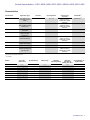
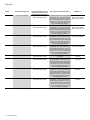
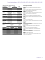
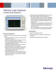
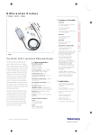
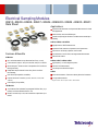
Electrical Sampling Modules
80E10 • 80E09 • 80E08 • 80E07 • 80E06 • 80E06X2 • 80E04 • 80E03 • 80E01
Data Sheet
Applications
Impedance Characterization and S-parameter Measurements for Serial
Data Applications
Advanced Jitter, Noise, and BER Analysis
Channel and Eye-diagram Simulation and Measurement-based Spice
Modeling
80E10, 80E08, and 80E04
High-performance TDR/T Measurements
Impedance Profile, Inductance, Capacitance, and S-parameters
Transmission Line Quality, Impedance, and Crosstalk
Features & Benefits
All Modules
Up to 70 GHz Bandwidth and 5 ps Measured Rise Time (10 - 90%)
True Differential, Common Mode, and Single-ended Measurements
Efficient Fault Isolation
80E09, 80E07, 80E06, 80E01
Lowest Noise for Analysis – 450 μVRMS at 60 GHz, 300 μVRMS at 30 GHz
High-frequency, Low-noise Signal Acquisition
Remote Samplers*1 Enable Location of Sampler Near DUT and Ensure
Best Signal Fidelity
Fast Rise Time Measurements
Independent Sampler Deskew Ensures Easy Fixture and Probe
De-embedding
Dual Channel (Except 80E01 and 80E06)
Precision Microwave Connectors (3.5 mm, 2.92 mm, 2.4 mm, and
1.85 mm)
Probe Support (Except 80E06)
TDR Modules
15 ps Reflected True Differential Fully Integrated TDR Rise Time (12 ps
Incident) and Feature Resolution Below 1 mm
Efficient, Accurate, Easy to Use, and Cost-effective S-parameters up to
50 GHz
Jitter Analysis and Waveform Analysis
80E03
Device Characterization, Transmission Quality, Waveform Parameters
Low Signal Measurements
*1 Integrated on 80E07 - 80E10 and optional on 80E01 - 80E04 and 80E06.
Data Sheet
TDR Modules: 80E10, 80E08, and 80E04
The 80E10, 80E08, and 80E04 are dual-channel Time Domain
Reflectometry (TDR) sampling modules, providing up to 12 ps incident
and 15 ps reflected rise time in the 80E10 (18 ps incident in 80E08 and
23 ps incident in 80E04). Each channel of these modules is capable of
generating a fast step for use in TDR mode and the acquisition portion of
the sampling module monitors the incident step and any reflected energy.
The polarity of each channel’s step can be selected independently. This
allows for differential or common mode TDR or S-parameters testing of
two coupled lines, in addition to the independent testing of isolated lines.
The independent step generation for each channel allows true differential
measurements, which ensures measurement accuracy for differential
devices.
The 80E10 and 80E08 are small form factor, fully integrated independent
2-meter remote sampler systems, enabling location of the sampler near the
DUT and ensuring the best signal fidelity. An optional 2-meter extender
is available for 80E04. The modules characterize crosstalk by using
TDR steps to drive one line (or line pair for differential crosstalk) while
monitoring a second line (or line pair) with the other channel (or another
module for differential crosstalk). The "filter" function on the 8200 and 8000
Series mainframes can be used with TDR or crosstalk measurements to
characterize expected system performance with slower edge rates.
All modules have independent incident step and receiver deskew to remove
the effect of measurement fixtures and probes, that enable faster and easier
de-embedding of test fixtures. The 80E10 sampling modules provide an
acquisition rise time of 7 ps, with up to 50 GHz user-selectable equivalent
bandwidth (with 50, 40, and 30 GHz settings). The 80E08 sampling
bandwidth is 30 GHz (user selectable with 30 and 20 GHz settings) and
80E04 sampling bandwidth is 20 GHz. The 20 GHz P8018 single-ended
and 18 GHz P80318 differential variable pitch TDR probes provide excellent
performance and compliance, ensuring easy and accurate backplane and
package measurements.
2
www.tektronix.com
When the user employs these modules with Tektronix IConnect® TDR and
VNA software, he or she can acquire up to 1,000,000 data points and obtain
up to 50 GHz differential, mixed mode, and single-ended S-parameters.
IConnect also enables impedance, S-parameters, and Eye-diagram
compliance testing as required by various serial data standards, as well as
full channel analysis, Touchstone (SnP) file output and SPICE modeling for
gigabit interconnects.
Sampling Modules: 80E09, 80E07, 80E06, 80E03, and
80E01
The 80E09 and 80E07 are dual-channel modules with remote samplers,
capable of 450 μVRMS noise at 60 GHz sampling bandwidth, and 300 μV
at 30 GHz sampling bandwidth. Each small form factor remote sampler
is attached to a 2-meter cable in order to minimize the effects of cables,
probes, and fixtures, allow close location of the sampler to the DUT, and
ensure best signal fidelity. User-selectable bandwidth settings (60/40/30 on
80E09 and 30/20 on 80E07) offer optimal noise/bandwidth trade-off.
80E06 and 80E01 are single-channel, 70+ and 50 GHz bandwidth sampling
modules. 80E06 provides the widest measurement bandwidth and fastest
rise-time measurements with world-class signal fidelity. Both 80E06 and
80E01 provide superior maximum operating range of ±1.6 V. Both of these
modules can be used with the optional 2-meter extender cable, which
ensures superior signal fidelity and measurement flexibility.
The 80E03 is a dual-channel, 20 GHz sampling module. This sampling
module provides an acquisition rise time of 17.5 ps or less. An optional
2-meter extender cable is available.
When used with Tektronix 80SJNB Jitter, Noise, and BER software, these
modules enable separation of both Jitter and noise into their components,
understand precise causes of Eye closure, and obtain highly accurate
extrapolation of BER and 3-D Eye contour. When used with 82A04 phase
reference module, time-base accuracy can be improved down to 200 fsRMS
Jitter, which together with the 300 μV noise floor and 14 bits of resolution
ensures the highest signal fidelity for the measured signals.
Electrical Sampling Modules — 80E10 • 80E09 • 80E08 • 80E07 • 80E06 • 80E06X2 • 80E04 • 80E03 • 80E01
Characteristics
Application Type
Channels
Input Impedance
Channel Input
Connector
Bandwidth*2
80E10
True differential TDR,
S-parameters, and fault
isolation
2
50 ±1.0 Ω
50/40/30 GHz*3, 4
80E09
High-frequency, low noise
signal acquisition and Jitter
characterization
2
50 ±1.0 Ω
80E08
True differential TDR and
S-parameters
Optimal noise/performance
trade-off for Jitter
characterization
High-speed electrical
device characterization
2
50 ±1.0 Ω
1.85 mm female, precision
adapter to 2.92 mm
included with 50 Ω SMA
termination
1.85 mm female, precision
adapter to 2.92 mm
included with 50 Ω SMA
termination
2.92 mm female
2
50 ±1.0 Ω
2.92 mm female
30/20 GHz*3, 4
1
50 ±0.5 Ω
70+ GHz
2
50 ±0.5 Ω
1.85 mm female, precision
adapter to 2.92 mm
included with 50 Ω SMA
termination
3.5 mm female
2
1
50 ±0.5 Ω
50 ±0.5 Ω
Characteristic
80E07
80E06
80E04
80E03
80E01
TDR impedance and
crosstalk characterization
Device characterization
High-frequency, high
maximum operating range
signal acquisition
3.5 mm female
2.4 mm female, precision
adapter to 2.92 mm
included with 50 Ω SMA
termination
60/40/30 GHz*3, 4
30/20 GHz*3, 4
20 GHz*3
20 GHz*3
50 GHz
*2 Values shown are warranted unless printed in an italic typeface which represents an unwarranted characteristic value that the instrument will typically perform to.
*3 Calculated from 0.35 bandwidth rise time product.
*4 User selectable.
Module
80E10
80E09
80E08
80E07
80E06
80E04
80E03
80E01
Rise Time
(10% to 90%)
7 ps*3
5.8 ps*3
11.7*3
11.7*3
5.0 ps*3
≤17.5 ps
≤17.5 ps
7 ps *3
Dynamic Range
1.0
1.0
1.0
1.0
1.0
1.0
1.0
1.0
Vp-p
Vp-p
Vp-p
Vp-p
Vp-p
Vp-p
Vp-p
Vp-p
Offset Range
±1.1
±1.1
±1.1
±1.1
±1.6
±1.6
±1.6
±1.6
V
V
V
V
V
V
V
V
Maximum
Operating Voltage
±1.1
±1.1
±1.1
±1.1
±1.6
±1.6
±1.6
±1.6
V
V
V
V
V
V
V
V
Maximum
Vertical Number of
Nondestruct
Digitized Bits
Voltage, DC + ACp-p
2.0
2.0
2.0
2.0
2.0
3.0
3.0
2.0
V
V
V
V
V
V
V
V
14 bits full scale
14 bits full scale
14 bits full scale
14 bits full scale
14 bits full scale
14 bits full scale
14 bits full scale
14 bits full scale
*3 Calculated from 0.35 bandwidth rise time product.
www.tektronix.com
3
Data Sheet
Module
Vertical Sensitivity Range
DC Vertical Voltage Accuracy,
Single Point, within ±2 °C of
Compensated Temperature
Typical Step Response Aberrations*2
RMS Noise*2
80E10
10 mV to 1.0 V full scale
±[2 mV + 0.007 (Offset) +
0.02 (Vertical Value - Offset)]
50 GHz: 600 μV, ≤700 μV
40 GHz: 370 μV, ≤480 μV
30 GHz: 300 μV, ≤410 μV
80E09
10 mV to 1.0 V full scale
±[2 mV + 0.007 (Offset) +
0.02 (Vertical Value - Offset)]
80E08
10 mV to 1.0 V full scale
±[2 mV + 0.007 (Offset) +
0.02 (Vertical Value - Offset)]
80E07
10 mV to 1.0 V full scale
±[2 mV + 0.007 (Offset) +
0.02 (Vertical Value - Offset)]
80E06
10 mV to 1.0 V full scale
80E04
10 mV to 1.0 V full scale
±[2 mV + 0.007 (Offset) +
0.02 (Vertical Value - Offset)]
±[2 mV + 0.007 (Offset) +
0.02 (Vertical Value - Offset)]
80E03
10 mV to 1.0 V full scale
±[2 mV + 0.007 (Offset) +
0.02 (Vertical Value - Offset)]
80E01
10 mV to 1.0 V full scale
±[2 mV + 0.007 (Offset) +
0.02 (Vertical Value - Offset)]
±1% or less over the zone 10 ns to 20 ps before
step transition; +6%, -10% or less for the first
400 ps following step transition; +0%, -4% or
less over the zone 400 ps to 3 ns following step
transition; +1%, -2% or less over the zone
3 ns to 100 ns following step transition; ±1%
after 100 ns following step transition
±5% or less for first 300 ps following
step transition
±3% or less over the zone 10 ns to 20 ps
before step transition; +10%, -5% or less for
the first 300 ps following step transition; ±3%
or less over the zone 300 ps to 5 ns following
step transition; ±1% or less over the zone
5 ns to 100 ns following step transition; 0.5%
after 100 ns following step transition
±3% or less over the zone 10 ns to 20 ps before
step transition; +10%, -5% or less for the first
300 ps following step transition; ±3% or less
over the zone 300 ps to 5 ns following step
transition; ±1% or less over the zone 5 ns to
100 ns following step transition; ±0.5% after
100 ns following step transition
±3% or less over the zone 10 ns to 20 ps before
step transition; +12%, -5% or less for the first
300 ps following step transition; +5.5%, -3%
or less over the zone 300 ps to 3 ns following
step transition; ±1% or less over the zone
3 ns to 100 ns following step transition; ±0.5%
after 100 ns following step transition
*2 Values shown are warranted unless printed in an italic typeface which represents a unwarranted characteristic value that the instrument will typically perform to.
4
www.tektronix.com
60 GHz: 450 μV, ≤600 μV
40 GHz: 330 μV, ≤480 μV
30 GHz: 300 μV, ≤410 μV
30 GHz: 300 μV, ≤410 μV
20 GHz: 280 μV, ≤380 μV
30 GHz: 300 μV, ≤410 μV
20 GHz: 280 μV, ≤380 μV
1.8 mV, ≤2.4 mV
(maximum)
600 µV, ≤1.2 mV
(maximum)
600 μV, ≤1.2 mV
(maximum)
1.8 mV, ≤2.3 mV
(maximum)
Electrical Sampling Modules — 80E10 • 80E09 • 80E08 • 80E07 • 80E06 • 80E06X2 • 80E04 • 80E03 • 80E01
Ordering Information
TDR System (80E10, 80E08, 80E04 only)
Characteristic
80E10
80E08
80E04
Channels
Input Impedance
Channel Input
Connector
Bandwidth
TDR Step
Amplitude
2
50 Ω nominal
1.85 mm
2
50 Ω nominal
2.92 mm
2
50 Ω nominal
3.5 mm
50 GHz
250 mV (polarity
of either step may
be inverted)
15 ps
30 GHz
250 mV (polarity
of either step may
be inverted)
20 ps
20 GHz
250 mV (polarity
of either step may
be inverted)
28 ps
12 ps
18 ps
23 ps
±250 ps
±250 ps
±50 ps
±250 ps
±250 ps
200 kHz
200 kHz
+100 ns -500 ps
(slot deskew only)
200 kHz
TDR System
Reflected Rise
Time
TDR System
Incident Rise Time
TDR Step Deskew
Range
TDR Sampler
Deskew Range
TDR Step
Maximum
Repetition Rate
Dual-channel, 50 GHz True Differential TDR Sampling Module with Remote
Samplers.
Includes: User manual, certificate of traceable calibration standard, two precision
adapters to 2.92 mm included with 50 Ω SMA terminations.
80E09
Dual-channel, 60 GHz Sampling Module.
Includes: User manual, certificate of traceable calibration standard, two precision
adapters to 2.92 mm included with 50 Ω SMA terminations.
80E08
Dual-channel, 30 GHz True Differential TDR Sampling Module with Remote
Samplers.
Includes: User manual, certificate of traceable calibration standard, two 50 Ω SMA
terminations.
80E07
Dual-channel, 30 GHz Sampling Module.
Includes: User manual, certificate of traceable calibration standard, two 50 Ω SMA
terminations.
80E06
Physical Characteristics
Module
80E10*5
80E09*5
80E08*5
80E07*5
80E06
80E04
80E03
80E01
80E10
Width
Dimension
(mm / in.)
Height
Depth
Weight
(kg / lb.)
Net
55 / 2.2
55 / 2.2
55 / 2.2
55 / 2.2
79 / 3.1
79 / 3.1
79 / 3.1
79 / 3.1
25 / 1.0
25 / 1.0
25 / 1.0
25 / 1.0
25 / 1.0
25 / 1.0
25 / 1.0
25 / 1.0
75 / 3.0
75 / 3.0
75 / 3.0
75 / 3.0
135 / 5.3
135 / 5.3
135 / 5.3
135 / 5.3
0.175 / 0.37
0.175 / 0.37
0.175 / 0.37
0.175 / 0.37
0.4 / 0.87
0.4 / 0.87
0.4 / 0.87
0.4 / 0.87
*5 Remote sampler module characteristics.
70+ GHz Electrical Sampling Module.
Includes: User manual, calibration data report, precision adapter to 2.92 mm with
50 Ω SMA termination.
80E06X2 – Bundled ordering configuration provides two 80E06 modules.
80E04
Dual-channel, 20 GHz True Differential TDR Sampling Module.
Includes: User manual, calibration data report, two 50 Ω SMA terminations.
80E03
Dual-channel, 20 GHz Sampling Module.
Includes: User manual, calibration data report, two 50 Ω SMA terminations.
80E01
Single-channel, 50 GHz Sampling Module.
Includes: User manual, calibration data report, precision adapter to 2.92 mm
included with 50 Ω SMA termination.
www.tektronix.com
5
Data Sheet
Service Options
Opt.
Opt.
Opt.
Opt.
Opt.
Opt.
Opt.
C3 – Calibration Service 3 Years.
C5 – Calibration Service 5 Years.
D1 – Calibration Data Report (not available with 80E07 - 80E10).
D3 – Calibration Data Report 3 Years (with Opt. C3).
D5 – Calibration Data Report 5 Years (with Opt. C5).
R3 – Repair Service 3 Years (including warranty).
R5 – Repair Service 5 Years (including warranty).
Other Accessories
Sampling Module Extender Cable (2-meter length) – Order 80N01 (not for use with
80E07 - 80E10).
2x Attenuator (SMA Male-to-Female) – Order 015-1001-xx.
5x Attenuator (SMA Male-to-Female) – Order 015-1002-xx.
Adapter (2.4 mm male to 2.92 mm female – can also be used as 1.85 mm male to
2.92 mm female) – Order 011-0157-xx.
P8018 – 20 GHz Single-ended TDR Probe. 80A02 module (below) recommended for
static protection of the sampling or TDR module.
P80318 – 18 GHz Differential TDR Probe. 80A02 module (below) recommended for
static protection of each channel of the sampling or TDR module.
80A02 – EOS/ESD Protection Module (1 channel). P8018 or P80318 TDR probe
(above) recommended.
6
www.tektronix.com
Interconnect Cables (3rd party)
Tektronix recommends using quality high-performance interconnect cables with
these high-bandwidth products in order to minimize measurement degradation
and variations. The W.L. Gore & Associates’ cable assemblies, accessible at
http://www.gore.com/tektronix, are compatible with the 2.92 mm, 2.4 mm, and
1.85 mm connector interface of the 80Exx modules. Assemblies can be ordered
by contacting Gore (at the URL above).
Calibration Kits and Accessories (3rd party)
To facilitate S-parameter measurements with these electrical modules and IConnect®
software, we recommend precision calibration kits, adapter kits, connector savers,
airlines, torque wrenches, and connector gauges from Maury Microwave. These
components, accessible at www.maurymw.com/tektronix.htm, are compatible with
the 2.92 mm, 2.4 mm, and 1.85 mm connector interface of the 80Exx modules. Cal
kits and other components can be ordered by contacting Maury Microwave (at the
URL above).
Product(s) are manufactured in ISO registered facilities.
Electrical Sampling Modules — 80E10 • 80E09 • 80E08 • 80E07 • 80E06 • 80E06X2 • 80E04 • 80E03 • 80E01
www.tektronix.com
7
Data Sheet
Contact Tektronix:
ASEAN / Australasia (65) 6356 3900
Austria +41 52 675 3777
Balkans, Israel, South Africa and other ISE Countries +41 52 675 3777
Belgium 07 81 60166
Brazil +55 (11) 3759-7627
Canada 1 (800) 661-5625
Central East Europe, Ukraine, and the Baltics +41 52 675 3777
Central Europe & Greece +41 52 675 3777
Denmark +45 80 88 1401
Finland +41 52 675 3777
France +33 (0) 1 69 86 81 81
Germany +49 (221) 94 77 400
Hong Kong (852) 2585-6688
India (91) 80-42922600
Italy +39 (02) 25086 1
Japan 81 (3) 6714-3010
Luxembourg +44 (0) 1344 392400
Mexico, Central/South America & Caribbean 52 (55) 54247900
Middle East, Asia, and North Africa +41 52 675 3777
The Netherlands 090 02 021797
Norway 800 16098
People’s Republic of China 86 (10) 6235 1230
Poland +41 52 675 3777
Portugal 80 08 12370
Republic of Korea 82 (2) 6917-5000
Russia & CIS +7 (495) 7484900
South Africa +27 11 206 8360
Spain (+34) 901 988 054
Sweden 020 08 80371
Switzerland +41 52 675 3777
Taiwan 886 (2) 2722-9622
United Kingdom & Ireland +44 (0) 1344 392400
USA 1 (800) 426-2200
For other areas contact Tektronix, Inc at: 1 (503) 627-7111
Updated 5 August 2009
For Further Information. Tektronix maintains a comprehensive, constantly expanding
collection of application notes, technical briefs and other resources to help engineers working
on the cutting edge of technology. Please visit www.tektronix.com
Copyright © Tektronix, Inc. All rights reserved. Tektronix products are covered by U.S. and foreign patents,
issued and pending. Information in this publication supersedes that in all previously published material.
Specification and price change privileges reserved. TEKTRONIX and TEK are registered trademarks of
Tektronix, Inc. All other trade names referenced are the service marks, trademarks, or registered trademarks
of their respective companies.
12 Aug 2009
www.tektronix.com
85W-13497-8