1
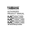
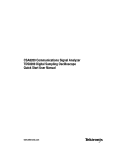
xx
ZZZ
82A04B
Phase Reference Module
User Manual
*P071312402*
071-3124-02
xx
ZZZ
82A04B
Phase Reference Module
User Manual
www.tektronix.com
071-3124-02
Copyright © Tektronix. All rights reserved. Licensed software products are
owned by Tektronix or its subsidiaries or suppliers, and are protected by national
copyright laws and international treaty provisions.
Tektronix products are covered by U.S. and foreign patents, issued and pending.
Information in this publication supersedes that in all previously published
material. Specifications and price change privileges reserved.
TEKTRONIX and TEK are registered trademarks of Tektronix, Inc.
Contacting Tektronix
Tektronix, Inc.
14150 SW Karl Braun Drive
P.O. Box 500
Beaverton, OR 97077
USA
For product information, sales, service, and technical support:
In North America, call 1-800-833-9200.
Worldwide, visit www.tektronix.com to find contacts in your area.
Warranty
Tektronix warrants that this product will be free from defects in materials and
workmanship for a period of one (1) year from the date of shipment. If any such product
proves defective during this warranty period, Tektronix, at its option, either will repair
the defective product without charge for parts and labor, or will provide a replacement
in exchange for the defective product. Parts, modules and replacement products used by
Tektronix for warranty work may be new or reconditioned to like new performance. All
replaced parts, modules and products become the property of Tektronix.
In order to obtain service under this warranty, Customer must notify Tektronix of the
defect before the expiration of the warranty period and make suitable arrangements for the
performance of service. Customer shall be responsible for packaging and shipping the
defective product to the service center designated by Tektronix, with shipping charges
prepaid. Tektronix shall pay for the return of the product to Customer if the shipment is to
a location within the country in which the Tektronix service center is located. Customer
shall be responsible for paying all shipping charges, duties, taxes, and any other charges
for products returned to any other locations.
This warranty shall not apply to any defect, failure or damage caused by improper use or
improper or inadequate maintenance and care. Tektronix shall not be obligated to furnish
service under this warranty a) to repair damage resulting from attempts by personnel other
than Tektronix representatives to install, repair or service the product; b) to repair damage
resulting from improper use or connection to incompatible equipment; c) to repair any
damage or malfunction caused by the use of non-Tektronix supplies; or d) to service a
product that has been modified or integrated with other products when the effect of such
modification or integration increases the time or difficulty of servicing the product.
THIS WARRANTY IS GIVEN BY TEKTRONIX WITH RESPECT TO THE
PRODUCT IN LIEU OF ANY OTHER WARRANTIES, EXPRESS OR IMPLIED.
TEKTRONIX AND ITS VENDORS DISCLAIM ANY IMPLIED WARRANTIES OF
MERCHANTABILITY OR FITNESS FOR A PARTICULAR PURPOSE. TEKTRONIX'
RESPONSIBILITY TO REPAIR OR REPLACE DEFECTIVE PRODUCTS IS THE
SOLE AND EXCLUSIVE REMEDY PROVIDED TO THE CUSTOMER FOR
BREACH OF THIS WARRANTY. TEKTRONIX AND ITS VENDORS WILL NOT BE
LIABLE FOR ANY INDIRECT, SPECIAL, INCIDENTAL, OR CONSEQUENTIAL
DAMAGES IRRESPECTIVE OF WHETHER TEKTRONIX OR THE VENDOR HAS
ADVANCE NOTICE OF THE POSSIBILITY OF SUCH DAMAGES.
[W2 – 15AUG04]
Table of Contents
Compliance information . . . . . . . . . . . . . . . . . . . . . . . . . . . . . . . . . . . . . . . . . . . . . . . .
ii
General safety summary . . . . . . . . . . . . . . . . . . . . . . . . . . . . . . . . . . . . . . . . . . .
ii
EMC compliance . . . . . . . . . . . . . . . . . . . . . . . . . . . . . . . . . . . . . . . . . . . . . . . . . . .
ii
Environmental considerations . . . . . . . . . . . . . . . . . . . . . . . . . . . . . . . . . . . . . iii
Getting started . . . . . . . . . . . . . . . . . . . . . . . . . . . . . . . . . . . . . . . . . . . . . . . . . . . . . . . . . . . . 1
Operating basics . . . . . . . . . . . . . . . . . . . . . . . . . . . . . . . . . . . . . . . . . . . . . . . . . . . . . . . . . . 5
Specifications . . . . . . . . . . . . . . . . . . . . . . . . . . . . . . . . . . . . . . . . . . . . . . . . . . . . . . . . . . . . . 9
82A04B User Manual
i
Compliance information
Compliance information
General safety summary
As this module is for use only when installed in the main instrument,
see the primary instrument user documentation for general safety
summary information.
Ground the product. This product is indirectly grounded through the
grounding conductor of the mainframe power cord. To avoid electric
shock, the grounding conductor must be connected to earth ground.
Before making connections to the input or output terminals of the
product, ensure that the product is properly grounded.
EMC compliance
As this module is for use only when installed in the main instrument,
see the primary instrument user documentation for EMC compliance
information.
ii
82A04B User Manual
Compliance information
Environmental considerations
This section provides information about the environmental impact of
the product.
Product end-of-life handling
Observe the following guidelines when recycling an instrument or
component:
Equipment recycling. Production of this equipment required the
extraction and use of natural resources. The equipment may contain
substances that could be harmful to the environment or human health
if improperly handled at the product’s end of life. To avoid release of
such substances into the environment and to reduce the use of natural
resources, we encourage you to recycle this product in an appropriate
system that will ensure that most of the materials are reused or recycled
appropriately.
This symbol indicates that this product complies with the
applicable European Union requirements according to
Directives 2002/96/EC and 2006/66/EC on waste electrical and
electronic equipment (WEEE) and batteries. For information
about recycling options, check the Support/Service section of
the Tektronix Web site (www.tektronix.com).
Restriction of hazardous substances
This product is classified as an industrial monitoring and control
instrument, and is not required to comply with the substance restrictions
of the recast RoHS Directive 2011/65/EU until July 22, 2017.
82A04B User Manual
iii
Compliance information
iv
82A04B User Manual
Getting started
Product description
The 82A04B Phase Reference Module extends the capability of the
DSA8300 1 Digital Serial Analyzer sampling oscilloscope mainframe by
providing extremely low jitter/low drift sample position information to
the mainframe. This sample position information is based on the phase
of a reference clock signal connected to the 82A04B input.
The benefits of using the sample position information based on a clock
signal are two-fold:
An extremely low jitter of <100 fsRMS.
The capability of a triggerless acquisition.
The typical application for the phase reference module is the acquisition
and analysis of very high speed optical and electrical signals in
high-speed computers, communication devices and systems, and similar
areas.
1
The 82A04B Phase Reference Module is also compatible with the DSA8200 Digital
Serial Analyzer, CSA8200 Communications Signal Analyzers, and the TDS8200 Digital
Sampling Oscilloscopes.
82A04B User Manual
1
Getting started
The 82A04B together with the DSA8300 implements the phase
reference timebase functionality in a novel way, giving the user
the freedom to select from timebase and acquisition modes. Any
phase-reference frequency within the operating range is accommodated,
and even the advanced features, such as FrameScan®, remain available.
The separate DSP per acquisition slot architecture of the DSA8300
enables the acquisition rate in the phase reference mode to reach over
180 kS/s.
Accessories
The following items are included with the 82A04B Phase Reference
Module:
SMA 50 Ω termination, Tektronix part number 015-1022-xx
1.85 mm (V) male to 2.92 mm (K) female adapter for connection
to 3.5 mm compatible male connectors, Tektronix part number
011-0187-xx
ESD protective transit case, Tektronix part number 016-2074-xx
20 inch SMA Cable, Tektronix part number 174-1427-xx
Two-meter sampling module extender cable (Tektronix part number
80X02)
2
82A04B User Manual
Getting started
Installing and removing the module
Refer to the host instrument documentation or the 80X01, 80X02
Electrical Sampling Module Extender Instructions for proper installation
and removal of modules and extender cables.
CAUTION. Instrument modules are extremely static sensitive. Always
ground yourself when handling modules.
The module is designed to install directly into any available
small-module compartment of the following Tektronix mainframes:
DSA8300
CSA8200, DSA8200, TDS8200
NOTE. Only one 82A04B module can be active in a mainframe at a time.
Connector care
Use extra care when attaching or removing SMA connectors. Use the
following guidelines to make proper connections:
1.
Align the connectors carefully before turning the nut.
2.
Use light finger pressure to lightly tighten the connection.
3.
Use a torque wrench to lightly tighten the nut as specified. (See
Table 1.) Use an open-end wrench to keep the body of the device
from turning.
4.
Rotate only the connector nut (not the cable) that you are tightening.
5.
Position the two wrenches within 90 degrees of each other before
applying force. (See Figure 1.)
6.
Hold the torque wrench lightly at the end of the handle.
7.
Apply downward force perpendicular to the wrench handle; this
applies torque to the connection through the wrench.
8.
Tighten the connection just to the point that the wrench breaks over.
Do not overtighten the connection.
82A04B User Manual
3
Getting started
Figure 1: Using a torque wrench to tighten connectors
Table 1: Torque wrench information
4
Connector type
Torque setting
Torque tolerance
SMA
56 N-cm (5 in-lb)
± 5.6 N-cm (± 0.5 in-lb)
1.85 mm
2.4 mm
2.92 mm
3.5 mm
90 N-cm (8 in-lb)
± 9.0 N-cm (± 0.8 in-lb)
82A04B User Manual
Operating basics
Operation
The operation of the Phase Reference module is based on the acquisition
of a reference clock signal that is synchronous to the signal being
measured. This clock is a user-supplied signal (such as a clock from a
BERT), or the Clock Output of one of the DSA8300 clock recovery or
optical modules. In addition, the user can connect an external trigger
signal to the Direct Trigger input or to the Clock Input/Prescaler Trigger
input of the mainframe.
Phase Ref Free-Run. With no external trigger to the DSA8300 mainframe
needed, the 82A04B module can, together with the mainframe, create
a timebase based on the phase of the reference clock. (Effectively, the
timebase of the instrument functions as a “Phase-base” instead). The
signal displayed on the screen will therefore repeat after one period of
the reference clock. All user controls remain enabled, even while the
horizontal position has relative meaning only. The timing information
presented by the oscilloscope is based solely on the phase reference
clock frequency as entered by the user in the Input Freq field of the
Phase Ref Setup dialog box. (See page 6, Setup controls.)
Phase Ref Triggered. By providing the phase reference clock to both
the phase reference module and the Clock Input of the instrument, the
DSA8300's Advanced Trigger feature (Option ADVTRIG) can acquire
repetitive pattern data (as opposed to only eye diagrams or clock
signals) with very low jitter.
Characterize. To operate properly in either the Phase Ref Triggered or
the Phase Ref Free-Run modes, the Phase Reference module has to
first Characterize the Phase Reference signal. The signal needs to be
stable during and after the characterization. The instrument indicates
when characterization is necessary.
82A04B User Manual
5
Operating basics
Setup controls
The controls for the 82A04B Phase Reference Module are contained
in the Phase Ref setup dialog box in the mainframe. Refer to the
mainframe online help for information about the control settings.
6
82A04B User Manual
Operating basics
Using extender cables with the 82A04B
You can install an 80X01 (1 meter) or 80X02 (2 meter) electrical
sampling module extender cable on the 82A04B to provide correct phase
reference clock signal alignment for different sampling module setups:
Always use the 80X02 cable provided with the 82A04B when using
remote sampling modules 80E07B, 80E08B, 80E09B or 80E10B
Always use the same extender cable length to extend the 82A04B
as you use for extending supported monolithic sampling modules
(such as the 80E01, 80E03, 80E04, or 80E11X1). For example, if
you use an 80X01 extender cable with an 80E11X1, also use an
80X01 extender cable with the 82A04B.
Refer to the 80X01 and 80X02 Electrical Sampling Module Extender
Instructions (Tektronix part number 071-3206-xx) for more information
on using extender cables with modules.
NOTE. Legacy module extender cable 80N01 can be used to extend
supported sampling modules and the 82A04B. The 80N01 cable is
equivalent to the 80X02 extender cable.
82A04B User Manual
7
Operating basics
8
82A04B User Manual
Specifications
Table 2: 82A04B electrical
Characteristics
Description
Applicable mainframes
DSA8300, DSA8200, TDS8200, CSA8200
Phase correction
capabilities and conditions
A phase reference signal can be applied
to a mainframe equipped with the 82A04B
Phase Reference Module to provide additional
phase information for signals being acquired
in Triggered Phase Corrected modes and
primary phase information for signals being
acquired in Free Run Phase Corrected modes.
For Phase Corrected Triggered modes, the
phase correction functionality overlays the
functionality of the basic trigger operation,
although restrictions might be imposed.
Number of phase
reference module inputs
One per 82A04B module. Up to three
82A04B modules can be inserted in the
small compartments of the mainframe and
characterized to operate with one or more
vertical sampling module(s); only one phase
correction module at a time can be used.
Input connector
Precision 1.85 mm female connector (V)
Input characteristics
(typical)
50 Ω AC coupled through 5 pF
Input dynamic range
(nonclipping)
2 Vp-p (offset ±1000 mV)
Input maximum
nondestruct range
±3 V maximum
Input signal level
600 mVp-p to 1.8 Vp-p to achieve typical
specified jitter performance
82A04B User Manual
9
Specifications
Table 2: 82A04B electrical (cont.)
Characteristics
Description
Phase reference mode
jitter
Triggered and Free Run Phase Corrected
Modes, 8 GHz - 60 GHz clock, 600 mV 1.8 Vp-p input: 100 fsRMS or better.
Triggered and Free Run Phase Corrected
Modes, 2 GHz - 8 GHz sine wave clock,
600 mV - 1.8 Vp-p input: 140 fsRMS or better.
The jitter increase between 8 GHz and 2 GHz
is roughly inversely proportional to clock
frequency.
Operation of phase reference clock at
frequencies below 8 GHz with non-sinusoidal
Clock signals may require an optional filter
accessory.
Compensation
temperature range
(typical)
±5 °C where compensation was performed.
If the compartment is changed on the
mainframe, or if the sampling module extender
is employed, or the length of sampling module
extender is changed, the Phase Reference
module must be recompensated.
Input operating frequency
10
82A04B
8 GHz to 32 GHz
82A04B-60 G
8 GHz to 60 GHz
82A04B User Manual
Specifications
Table 2: 82A04B electrical (cont.)
Characteristics
Description
Input operating frequency
(typical)
82A04B
2 GHz to 32 GHz usable range
Operation below 8 GHz with a non-sinusoidal
clock typically requires the use of external
filters, as follows:
2 GHz to 4 GHz: requires 2.2 GHz peaked
lowpass filter kit, Tektronix part number
020-2566-00.
4 GHz to 6 GHz: requires 4 GHz
lowpass filter kit, Tektronix kit part number
020-2567-00
6 GHz to 10 GHz: requires 6 GHz filter
lowpass filter kit, Tektronix kit part number
020-2568-00
82A04B-60 G
2 GHz to 60 GHz usable range. Operation
below 8 GHz may require the use of external
filters as noted for the standard 82A04B
2 GHz to 110 GHz settable range
Table 3: 82A04B mechanical and environmental
Characteristics
Description
Weight
0.4 kg (13 oz)
Dimensions
Height
25 mm (1.0 in)
Width
79 mm (3.1 in)
Depth
135 mm (5.3 in)
Environmental
conditions
Refer to the host instrument specifications.
Electromagnetic
compatibility
Refer to the host instrument specifications.
82A04B User Manual
11
Specifications
Table 4: Mainframe system timebase
Characteristics
Description
Mainframe horizontal
modes
Free Run and Triggered Modes are supported
Mainframe sampling
rate, phase corrected
modes
DC to 180 kHz maximum, one channel. If the
trigger rate is less than the maximum, or the
requested holdoff exceeds the minimum, then the
trigger rate and / or holdoff will dictate sampling
rate.
Mainframe horizontal
position range
Range is determined by the following formula
where (f) equals the frequency of the reference
clock
Mainframe timing
accuracy, free run
phase corrected mode
Maximum timing deviation 0.1% of phase
reference signal period, typical, relative to phase
reference signal
Assumes that phase reference frequency has
been correctly entered. Operation of phase
reference clock at frequencies requiring extended
bandwidth or signal conditioning may require an
instrument option.
Mainframe timing
accuracy, triggered
phase corrected mode
Maximum timing deviation relative to phase
reference signal:
0.2% of the phase reference signal period
typical for measurements made >40 ns after
trigger event
0.4% of the phase reference signal period
typical for measurements made ≤40 ns after
the trigger event
Assumes that phase reference frequency
has been correctly entered
Mainframe horizontal
deskew range and
resolution
12
Operating in Triggered Phase Corrected modes:
-500 ps to +100 ns on any individual channel in
1 ps increments
Operating in Free Run Phase Corrected modes:
Deskew range extends over the full clock cycle
of the phase reference
82A04B User Manual
Specifications
Table 5: Mainframe system trigger
Characteristics
Description
Trigger sources
A phase reference signal may be applied to
the instrument, when equipped with an 82A04B
Phase Reference Module, to provide additional
phase information for signals being acquired in
Triggered Phase Corrected modes and primary
phase information for signals being acquired in
Free Run Phase Corrected modes.
Two bandwidth options are available for the
82A04B module and may be required over
specific frequency ranges of operation:
The base product has an 8 GHz to 32 GHz
range of operation
Option 60 G extends the upper frequency
range of operation to 60 GHz
82A04B User Manual
13