1
COMPUTATIONS WITH Abaqus RESULTS
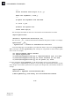
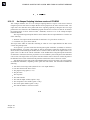
•
•
•
•
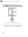
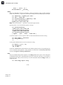
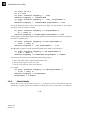
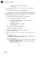
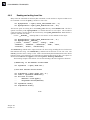
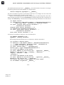
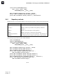
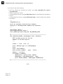
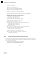
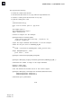
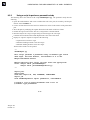
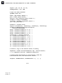
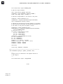
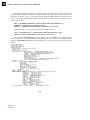
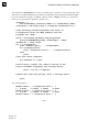
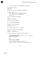
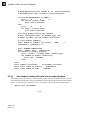
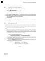
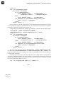
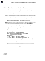
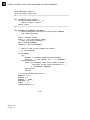
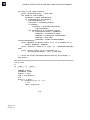
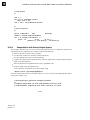
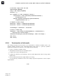
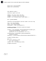
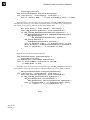
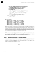
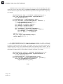
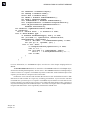
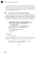
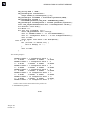
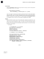
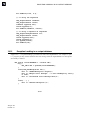
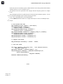
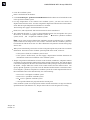
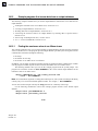
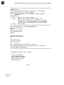
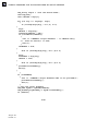
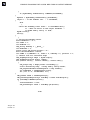
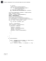
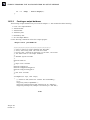
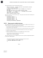
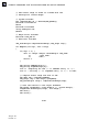
Create the coordinate system.
Retrieve the field from the database.
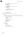
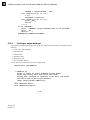
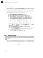
Use the fieldOutput.getTransformedField method to obtain a new field with the results
in the specified coordinate system.
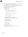
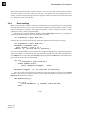
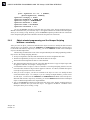
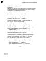
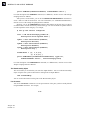
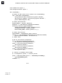
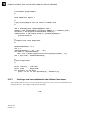
For large displacement of the structure and coordinate system, you must also retrieve the
displacement field at the frame. You must compute this displacement field for the whole model to
ensure that the required displacement information is available.
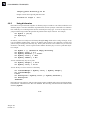
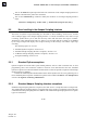
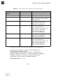
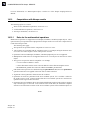
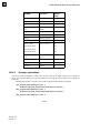
The following rules apply to the transformation of results:
•
•
Beams, truss, and axisymmetric shell element results will not be transformed.
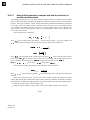
The component directions 1, 2, and 3 of the transformed results will correspond to the system
directions X, Y, and Z for rectangular coordinate systems; R, , and Z for cylindrical coordinate
systems; and R, , and for spherical coordinate systems.
Note: Stress results for three-dimensional continuum elements transformed into a cylindrical
system would have the hoop stress in S22, which is consistent with the coordinate system axis
but inconsistent with the stress state for a three-dimensional axisymmetric elements having hoop
stress in S33.
•
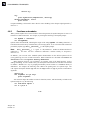
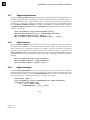
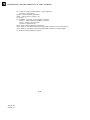
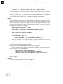
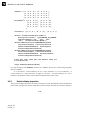
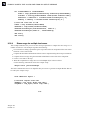
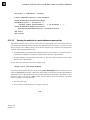
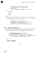
When you are transforming a tensor, the location or integration point always takes into account the
deformation. The location of the coordinate system depends on the model, as follows:
– If the system is fixed, the coordinate system is fixed.
– If the system is model based, you must supply a displacement field that determines the
instantaneous location and orientation of the coordinate system.
•
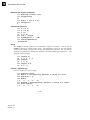
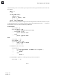
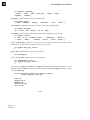
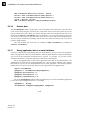
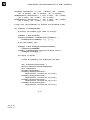
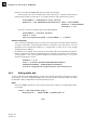
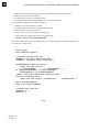
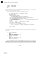
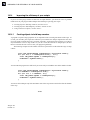
Abaqus will perform transformations of tensor results for shells, membranes, and planar elements
as rotations of results about the element normal at the element result location. The element normal
is the normal computed for the frame associated with the field by Abaqus, and you cannot redefine
the normal. Abaqus defines the location of the results location from the nodal locations. You
specify optional arguments if you want to use the deformed nodal locations to transform results.
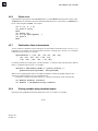
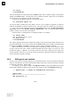
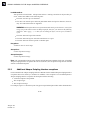
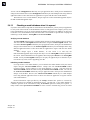
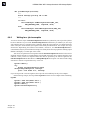
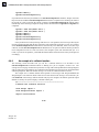
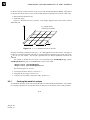
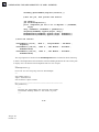
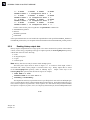
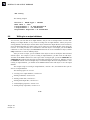
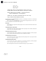
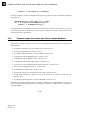
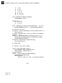
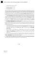
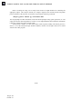
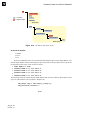
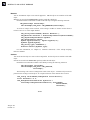
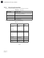
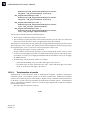
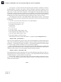
For rectangular, cylindrical, and spherical coordinate systems the second component direction for
the transformed results will be determined by one of the following:
– The Y-axis in a rectangular coordinate system.
– The -axis in a cylindrical coordinate system.
– The -axis in a spherical coordinate system.
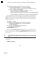
– A user-specified datum axis projected onto the element plane.
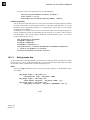
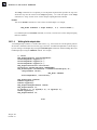
If the coordinate system used for projection and the element normal have an angle less than the
specified tolerance (the default is 30°), Abaqus will use the next axis and generate a warning.
10–57
Abaqus ID:
Printed on: